1
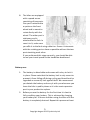
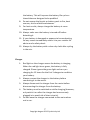
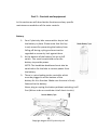
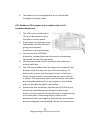
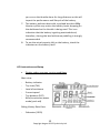
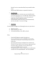
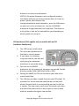
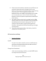
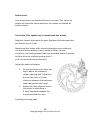
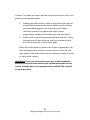
Owner’s Manual CycloTricity Electric Bicycles August 2013 3rd edition We strongly recommend you read this entire manual before using your bike. 1 Copyright August 2013 Cyclotricity Ltd Contents Part 1 – Before use - Page Before first time use Battery care Charger Water Maintenance Specifications 3 5 7 8 8 9 Part 2 – Controls and Equipment - Battery LCD handlebar dashboard LCD Instructions and Setup LED handlebar dashboard Pedal Assistance System (PAS) Throttle Brake levers Disc brakes V-Brakes 10 11 12 15 19 19 20 20 22 - Controller 24 Controller connections guide 26 Part 3 – Troubleshooting and Warranty - Troubleshooting Warranty Exceptions to limited warranty 2 Copyright August 2013 Cyclotricity Ltd 27 28 29 Part 1 – Before first time use The bike has been 90% readily assembled for you. To save space in the carton, it was packed with the front wheel, handlebars, pedals and possibly the seat posts detached. If you are not familiar with how to perform these fittings, we strongly recommend you seek assistance of a professional bike service shop as damages caused by wrong assembly is NOT covered by your warranty. A bike service shop will also adjust your brakes and gears for you for best performance. On the other hand, if you choose to perform these tasks by yourself, you will need the following tools: 1234- 5mm hex key 10mm wrench Screw driver Pump Although your Cyclotricity bike has been thoroughly tested, it is important that you perform some basic checks before first time use. You are also recommended to perform these checks regularly in the future to protect yourself and your Cyclotricity bike: 1- Check brakes and brake isolators are functioning properly. 2- Check all other nuts, bolts and fixings are properly tightened, pay particular attention to the motor fixings. You will notice that there is an unusual washer with a small axle around the motor spindle (called torque 3 Copyright August 2013 Cyclotricity Ltd washer). Make sure that the axle of the washer slides inside the fork opening. 3- Check the handlebar is properly tightened. 4- Check that there are no apparent loose/exposed connections between the electrical parts and the controller. 5- Check tyres are inflated and not damaged (there is no specific tyre pressure required, find out what best works for your weight). 6- Make sure battery is fully charged. 7- Ensure the handlebar dashboard is on. You will need to have the battery switch on, then pressing the on/off button on the handlebar dashboard for this to happen. Remember to turn the handlebar dashboard off when stopped or walking the bike. LCD dashboard LED dashboard 4 Copyright August 2013 Cyclotricity Ltd 8- The bikes are equipped with a speed sensor consisting of two parts. One part is attached to a spoke on the front wheel and is meant to rotate freely with the wheel. The other part is stationary and is attached to the fork. In case it isn’t, make sure you affix it to the fork using cable ties. Ensure it intersects with the rotating part as close as possible without the two parts touching each other. If you performed this stage correctly, you should be able to see your travel speed on the handlebar dashboard. Battery care 1- The battery is detachable and comes with a key to lock it in place. Please note that the battery lock is only meant to prevent it from falling off during cycling and should not be regarded as a security lock against theft. We recommend you detach the battery and carry it with you whenever you leave the bike in public places as it is the most expensive part in your product to replace. 2- Before you use the battery for the first time it is best to fully condition your battery. This is achieved by charging your battery for 12 hours and then using the bike until the battery is completely drained. Repeat this process at least 5 Copyright August 2013 Cyclotricity Ltd three times. After this “conditioning” process, you can leave the battery charging as and when you require. 3- The amount of capacity left on the battery can be checked by pressing the button at the top of the battery. The indicators on the battery will gradually turn green as the battery is charging. NOTE: One indicator on the battery will remain red no matter how long you charge the battery for technical reasons. This does not mean the battery is not fully charged. To know whether or not the battery is fully charged, please check the indicator on the actual charger. 4- The battery must be switched on while charging (however, only switch it on after the charger has been securely plugged in to avoid risk of short circuits). 5- If you are going to leave your battery uncharged for more than eight weeks, it is best left half charged. You should then re charge it every four weeks for two hours to keep it in top condition. 6- Always remember that you use up to three times more power when setting off under the thumb throttle. To preserve the life of each charge always set off using pedal assist. 7- Check the indicators on the actual battery to see how much power you have left. Please note that the indicators on the handlebar dashboard do not necessarily show the amount of power you have left, but the amount of load the battery is experiencing at any one point. If the dashboard indicators go under 2 levels, then this is a strong indication that you ought to be pedalling more to take some of the load off 6 Copyright August 2013 Cyclotricity Ltd 891011- 12- the battery. This will improve the battery life cycle as these bikes are designed to be pedalled. Do not expose the bicycle or battery pack to fire, heat sources, acid or alkaline substances. For best results, always charge the battery at room temperature. Always make sure the battery is turned off before detaching it. If your battery is damaged or appears to be overheating for any reason immediately return it to your retailer for advice and a safety check. Always dry the battery with a clean dry cloth after cycling in the rain. Charger 1- Red light on the charger means the battery is charging. When the red light turns green, the battery is fully charged. Please ignore the green light and carry on charging for 12 hours for the first 3 charges to condition your battery. 2- Always connect the charger to the battery before connecting it to the mains. 3- Always disconnect the charger from the mains before disconnecting the charger from the battery. 4- The battery must be switched on while charging (however, only switch it on after the charger has been securely plugged in to avoid risk of short circuits). 5- Do not leave the charger connected to the mains when not in use. 7 Copyright August 2013 Cyclotricity Ltd Water Your electric bicycle is rain and splash resistant and can be used in all weathers. The electrical components of the vehicle, such as motor, battery, and controller, must not be submerged in water. Maintenance WARNING: Do not attempt to open the casings of the battery or motor as it could be dangerous and all warranties will become void. If you experience problems, refer to the troubleshooting guide in this manual or ask your local dealer. 1- The brake leavers should lock the wheels when compressed half way between their open position and touching the handle bars. If not please adjust following the instructions in this manual or seek assistance of a local bike service shop. Warning: Any replacement forks must have the same rake and same tube inner diameter as the originally fitted to the bicycle. 2- Disc brake pad wear and replacement. Remove the brake pads and check them for wear. If the friction material is less than 1mm thick then they need to be replaced. Rear brake blocks must be replaced if the grooves are no longer visible. 3- Every three months lubricate the brake lever pivots, the gears and chain with light oil and the brake arm bushes (not the brake blocks or disc pads) with a little grease. 8 Copyright August 2013 Cyclotricity Ltd 4- Once a year, have your dealer re-grease the headset bearings, front wheel bearings and pedal bearings. 5- Wheel spokes should be adjusted after 300 miles riding. Specifications Battery range: 30-50km between charges depending on terrain, weight of cyclists, frequent use of Throttle instead of PAS, frequency of stops/starts, air pressure in tires etc. Bottle Battery type: Lithium-ion 36V/9Ah Pannier Battery type: Lithium-ion 36V/10Ah Speed: 25km/h (15.5mph) Motor type: High speed brushless geared hub motor Motor power: 250W Motor voltage: 36V Frame material: Alloy 6061 Fork material: ZOOM alloy front fork Derailleur: Shimano Wheels: Alloy double walled 9 Copyright August 2013 Cyclotricity Ltd Part 2 – Controls and equipment In this section we will describe the functions and any specific maintenance needed on all the main controls. Battery 1- Your Cyclotricity bike comes with a key to lock the battery in place. Please note that this key is only meant for preventing the battery from falling off during cycling and must not be regarded as a security lock against them. 2- At the bottom of the battery lies an on/off switch. This must be switched on for the battery to provide power. NOTE: The handlebar dashboard must also be switched on for the bike to receive power from the battery. 3- There is a wire leading to the controller which must be plugged in at the bottom of the battery for it to function. Make sure the wire is firmly fastened to the battery. Never plug or unplug the battery without switching it off first (failure to do so constitute risk of short circuits). 10 Copyright August 2013 Cyclotricity Ltd 4- The battery can be charged either on or off the bike through the charger input. LCD Dashboard (This applies only to models with an LCD handlebar dashboard) 1- The LCD has an on/off switch. This must be switched on for the bike to receive power. 2- If you leave it on without using the throttle, the bike will start giving you automatic assistance as you pedal along. 3- You can use the UP/DOWN buttons to increase/decrease the amount of assistance you would like the bike to provide. 4- Switching the power off will transform your bike into a normal push bike. 5- The LCD also provides other functions such as speed, time, distance of your journey etc (see LCD instructions). To achieve this, ensure that the speed sensor on the front wheel intersects with a corresponding part on the fork as it rotates. The two sensor parts must not touch each other but should be positioned in a way to get as close to each other as possible during the intersection. 6- Please note that the battery function on the LCD may not necessarily show the amount of capacity left on the battery, but the amount of load the battery is experiencing at any one point. Decreasing battery levels on the dashboard means you ought to be pedalling more as these bikes are designed to be pedalled. We do not recommend 11 Copyright August 2013 Cyclotricity Ltd you run on the throttle alone for long distances as this will impact the performance and lifecycle of the battery. 7- The battery performs best with a payload less than 80Kg. Heavier cyclists may notice the battery levels dropping on the dashboard as the throttle is being used. This is an indication that the battery is getting overloaded and, therefore, sharing the load with some pedalling is strongly recommended. 8- To see the actual capacity left on the battery, check the indicators on the battery itself. LCD Instructions and Setup Display under common running conditions Main view - Battery indicator Trip time (TM) Level of assistance Current speed Trip distance (DST) 6Km/h assistance power mode (push aid) Riding History Data View - Odometer (ODO) 12 Copyright August 2013 Cyclotricity Ltd - Maximum speed (MAX) Total trip time (TTM) Average speed (AVG) Function of buttons The LCD device comes with three buttons; the centre buttons is market with SW, whiles the UP/DOWN buttons are marked with arrows accordingly. On/Off - To switch the device on, press the SW button. To switch it off, press and hold the SW button (or the device will automatically switch off when the bike is left without use for 5 minutes). Change level of assistance - Under normal operating conditions, use the UP/DOWN buttons to change the level of assistance. Level 1 being the lowest, and 5 being the highest. Illuminate screen - Under normal operating conditions, press and hold the UP button to have the screen illuminate for use in the dark. Push aided mode - It is possible to use the 6km/h assistance mode while walking your bike. To do so, press and hold the DOWN button, the push aided indicator will start flashing. The 13 Copyright August 2013 Cyclotricity Ltd - bike will run at no more than 6km/h as you walk the bike along. Release the DOWN button to suspend this function. Trip Data View To enter the history trip data view, press the SW button once while the device is on. The ODO and TTM will appear. Press the UP/DOWN buttons to access the maximum speed and average speed information. Press SW again to exit this view (or it will automatically exit this view after 5 minutes of riding). User Setup You will need to configure the following functions on your device: a. b. c. Maximum speed. Wheel diameter (16”-28”). Unit selection (Miles or Km, MPH or Km/h). Setup - - - Press the SW button to switch the device on. Press and hold both the UP and DOWN buttons at the same time for 3 seconds. This will take you into the LCD setup view. Your device will come pre-configured to a maximum of 25km/h (15.5mph) which is the maximum legal speed limit for electric bikes in Europe. You can reduce this by pressing the DOWN button if you wish. Having adjusted the maximum speed, press the SW button to move on to the wheel diameter. Use the UP/DOWN 14 Copyright August 2013 Cyclotricity Ltd - button to set the correct diameter. NOTE: If the wheel diameter is not configured properly, the display will give you wrong outputs when it comes to power, speed, time distance etc. Having adjusted the wheel diameter, press the SW button to move on to the unit selection. Use the UP/DOWN buttons to change between Km/h and Mph. The distance units (miles or km) will be selected for you depending on which speed unit you pick. LED dashboard (This applies only to models with an LED handlebar Dashboard) 1- The LED has an on/off switch. This must be switched on for the bike to receive power. 2- If you leave it on without using the throttle, the bike will start giving you automatic assistance as you pedal along. 3- You can use the MODE buttons to set the amount of assistance you would like the bike to provide (LOW, MEDIUM, HIGH or OFF). 4- Setting the MODE to OFF will transform your bike into a normal push bike. 5- The LED also provides a speed function (see LED setup). To activate this, ensure that the speed sensor on the front wheel intersects with a corresponding part on the fork as it rotates. The two sensor parts must not touch each other but should be positioned in a way to get as close to each other as possible during the intersection. 15 Copyright August 2013 Cyclotricity Ltd 6- Please note that the battery indicators on the LED may not necessarily show the amount of capacity left on the battery, but the amount of load the battery is experiencing at any one point. Decreasing battery levels on the dashboard means you ought to be pedalling more. We do not recommend you run on the throttle alone for long distances as this will impact the performance and lifecycle of the battery. 7- The battery performs best with a payload less than 80Kg. Heavier cyclists may notice the battery levels dropping on the dashboard as the throttle is being used. This is an indication that the battery is getting overloaded and, therefore, sharing the load with some pedalling is strongly recommended. 8- To see the actual capacity left on the battery, check the indicators on the battery itself. LED Instructions and Setup Function of buttons On/Off - To switch it the device on/off, press the on/off button (or the device will automatically switch off when the bike is left without use for 5 minutes). Change level of assistance - Under normal operating conditions, use the MODE button to change the level of assistance. 16 Copyright August 2013 Cyclotricity Ltd Push aided mode - - It is possible to use the 6km/h assistance mode while walking your bike. To do so, press and hold the 6km/h button, the push aided indicator will start flashing. The bike will run at no more than 6km/h as you walk the bike along. Release the 6km/h button to suspend this function. User Setup You will need to configure the following functions on your device: d. e. Maximum speed. Wheel diameter (12”-28”). Speed Setup - - - Press the on/off button to switch the device on. Press and hold both on/off and MODE buttons simultaneously for 3-5 seconds. This will take you into the LED setup state. Once you enter the setup state, the LOW indicator as well as the speedometer indicators will flash. Press the on/off or MODE buttons to increase/decrease the maximum speed parameter (please note that 25km/h is the maximum legal speed limit allowed on the road in the UK/EU). Each light on the speedometer indicators equates to 1km/h. You can save this setting and exit the setup state by holding down the MODE button. Alternatively, you can 17 Copyright August 2013 Cyclotricity Ltd stay on the setup state and move on to configuring the wheel diameter by pressing the 6km/h button. Wheel Diameter Setup - - - Having adjusted the maximum speed and pressed the 6km/h button, you are now in the wheel diameter setup state. You will notice that the MED indicator as well as the speedometer indicators is flashing. Press on/off or MODE to set the right size of your wheel: The first of the speedometer lights corresponds to a 12” wheel. The second light corresponds to a 14” wheel. Thereafter 16”, 18”, 20”, 22”, 24”, 26”, 700c and th 28” in this order. I.e. the 10 light will correspond with a 28” wheel. NOTE: Choosing the wrong wheel size will result in nonaccurate speed readings on your LED speedometer. Press and hold the MODE button to save your settings and exit the setup state. NOTE: The LED will exit the setup state automatically if no buttons have been pressed for more than 1 minute. In which case, your settings will not be saved. 18 Copyright August 2013 Cyclotricity Ltd Pedal Assistance System (PAS) When you first ride your Cyclotricity bike you will notice that after one turn of the pedals the motor will start working, assisting you ride the bike by adding power to the front wheel, this is the standard mode. To continue using this mode you must keep turning the pedals. If you stop the motor will stop and the bike will slow to a halt. If you start pedalling again after one turn the motor will start again. NOTE: When you increase the amount of assistance on the handlebar dashboard, you will find that the battery range is reduced. Throttle 1- The throttle can be used independently to the PAS mode, but the operation will vary depending on the country where the bike is supplied. Bikes are set up to be legal in the region in which they are supplied and will provide full power (100%) independently of the PAS. 2- The independent use of the throttle, when available, will enable you to use the throttle without pedalling. 3- The use of the throttle in PAS mode is legal in most countries. Throttle in PAS mode enables you to turn up the power to the motor as long as you are pedalling the bike, if you stop pedalling the motor will stop too. 19 Copyright August 2013 Cyclotricity Ltd Brakes levers Your brakes levers are fitted with electric cut outs. This means no power will reach the motor whenever the brakes are applied for safety reasons. Disc Brakes (This applies only to models with disc brakes) Regularly inspect brake pads for wear. Replace disc brake pads that are thinner than 1.0 mm. Mechanical disc brakes offer several advantages over traditional rim brakes better braking in wet, muddy or other adverse conditions, less braking power fade over extended downhill braking and the ability to continue braking even if your rim becomes bent or distorted. Adjust the pads and calipers 1- On the disc brake use a 5mm hex key to adjust the stationary caliper adjusting bolt. Adjust the bolt so that there is 0.3mm clearance between the stationary (hub side) pad and the rotor. 2- Adjust the cable-adjuster bolt on the caliper so that there is 0.3mm clearance between the outside pad and the rotor. Installing/removing pads 20 Copyright August 2013 Cyclotricity Ltd Caution: The pads and rotor must be kept clean and free from oil or grease based contamination. 1- Holding the pad end-tab, insert it into caliper slot with its metal backing towards the piston. Make sure the hole in the metal backing goes over the piston pins. When correctly inserted, the pad will be held in place magnetically, repeat the procedure for the other pad. 2- Pads can be removed by grasping the pad end-tab, lifting the pad clear of the piston pin and then manoeuvring it out of the rotor slot in the caliper body. Note: Disc brake pads are held in the caliper magnetically. No tools are required to install or remove them. As the left and right pads are the same they may be inserted on either the left or right of the caliper. WARNING: If you are unsure about any part of the installation process you should seek advice from a professional bike service centre. Damage due to wrong adjustments will NOT be covered by your warranty. 21 Copyright August 2013 Cyclotricity Ltd V-Brakes (This applies only to models with V-brakes) Adjusting brakes and refitting brake pads 1- Use a 5mm Allen key to loosen bolt “A” to release the cable. Use a 5mm Allen key to loosen bolt “C” (right & left), then remove the spacers and washer. 2- Install new brake pads (if necessary), then with both pads pressed against the wheel rim, ensure that distance-B (in diagram) does not exceed 65mm. To decrease distance-B, exchange wide & narrow spacers on each brake pad. Before finally tightening brake pads, make sure they are aligned correctly on the rim, and there is a gap of 1mm between the top of the rim and the top of the pad. Hold each pad against the rim (one at a time) & tighten “C” bolt. Final tightening Torque: 6-8N.M 3- Refit the cable to bolt “A”, slot cable guide pipe into holder and fit protector over guide pipe end. Adjust cable in bolt “A” so that combined pad/rim clearance (the gap from left pad to left rim surface and from right pad to right rim surface) is 2mm, then tighten bolt “A”. Final tightening torque: 6-8N.M. 4- Balance brake arms by turning screw “D”. Apply the rear brake lever a few times while checking to see that tension is equal for both arms. Pad/rim contact should occur at 22 Copyright August 2013 Cyclotricity Ltd the same time each side. Clearance should be 1mm each side. Do not set the tension too high. WARNING: If you are unsure about any part of the installation process you should seek advice from a professional bike service centre. Damage due to wrong adjustments will NOT be covered by your warranty. 23 Copyright August 2013 Cyclotricity Ltd Controller The controller is the brain of the bike. As such, all electric parts must be connected through it to function. The controller is located inside a plastic box attached to the frame as demonstrated in this drawing. Alternatively, if your model is fitted with a pannier battery type, it will be housed in a compartment next to the battery: 24 Copyright August 2013 Cyclotricity Ltd The drawing to the right is how the controller looks like inside the plastic box. All the electrical devices on your bike should have been pre-connected to the controller by the time the bike reaches you. However, if you ever face problems with your bike, you may want to open the plastic box and double check that there are no loose or wrong connections to the controller. In most cases, you do not need to do this. On the other hand, if you would like to troubleshoot a problem, follow the connections guide in the next page to understand how your controller is meant to be set up. All wires coming out of the controller are either uniquely shaped or colour coded to prevent wrong connections. All you have to do is match the colours and shapes. The next page shows a diagram of all the wires and how/where they should be connected. WARNING: Please do NOT open the metal box of the controller itself. Doing so will void your warranty and may cause a safety hazard. 25 Copyright August 2013 Cyclotricity Ltd Controller connections guide 26 Copyright August 2013 Cyclotricity Ltd Part 3 - Troubleshooting and Warranty Troubleshooting Problem Possible reasons Possible solutions Speed is too slow 1-Low battery capacity 2-Max speed on LCD/LED is not configured properly 3-Handlebar dashboard problem. 4-Battery overloaded. 5-Damage to motor. No drive from motor 1-Battery unplugged 2-Motor unplugged from controller 3-Throttle damaged or unplugged from controller 4-Handlebar dashboard damaged or unplugged from controller 5-Controller damaged 6-Motor damaged 1-Fully charge battery 2-Refer to the LCD/LED instructions in this manual to change the MAX speed. 3-Contact your dealer for replacement. 4- The battery performs best with payload less than 75Kg. Make sure you combine throttle power with manual pedalling. 5-Ask your dealer to fit another motor and test the speed. 1-Check battery connection. 2-Open controller plastic box and check connection. 3-Check if you get drive using pedal assist. If there is drive, check throttle connection to controller. Contact your dealer for replacement if damaged. 4-If no lights on 27 Copyright August 2013 Cyclotricity Ltd Driving range is very low. I.e. less than 10km (6 miles). 1-Tyre pressure too low 2-Undercharged battery 3-Hill climbing, frequent stops, head wind, overloading. 4-Fault with charger. 5-Battery capacity loss. dashboard, ask your dealer to fit new dashboard and check the difference. 5-If none of the above worked, ask your dealer to fit a new controller and check the difference. 6-As a last resort, ask your dealer to fit a new motor to verify whether your old motor is damaged. 1-Pump the tyres. 2- Re-condition the battery by charging it for 12 hours and using it until completely drained. Repeat 3 times. 3-Use pedal assist and try to avoid running on throttle only as these bikes are designed to be pedalled. 4-Ask your dealer to charge your battery with a new charger to verify if any difference. 5-If none of the above works, replace battery. 28 Copyright August 2013 Cyclotricity Ltd Warranty Only use this product in accordance with this user manual. We offer a 1 year warranty limited to the following items on your bike. The warranty only covers technical faults which have not been in anyway caused by the user deliberately or accidentally. 12345678- The main frame Hub motor and motor shell Handlebar dashboard Electric brake levers (excluding brake shoes, callipers and pads) Controller Throttle Pedal assistance device Battery (including loss of range to under 10km (6miles) while using pedal assist only). NOTE: Delivering the bike back to your dealer for repair will be at your own expense. You are, therefore, recommended to follow the troubleshooting instructions in this guide as much as you can to identify the faulty parts and send them separately for replacement. Those parts and/or products which are determined by Cyclotricity to be defective and to qualify for warranty replacement will be provided at no charge, only after a valid warranty claim is processed by Cyclotricity. Warranty claims must be made by the original purchaser by contacting the original Cyclotricity dealer within the warranty period. Shipping & Handling fees will apply to all orders placed for warranty parts and/or products and will be invoiced to the 29 Copyright August 2013 Cyclotricity Ltd customer/warranty claimant prior to said parts and/or products are shipped from Cyclotricity. Cyclotricity, at its sole discretion, has the option of replacing with a new part, or factory re-certified part. The Limited Warranty stated herein is in lieu of and expressly excludes all other warranties not expressly set forth herein, whether expressed or implied by law or otherwise, including, but not limited to, any warranties for merchantability and/or fitness for any particular purpose. Cyclotricity shall in no event be liable or responsible for incidental or consequential losses, damages or expenses in connection with their products. The liability of Cyclotricity hereunder is expressly limited to the replacement of goods complying with this warranty or at the sole discretion of Cyclotricity to the repayment of an amount equivalent to the purchase price of the product in question. NOTE: Damaged caused by water, dropping or any collision is NOT covered. Exceptions to limited Warranty 1- Damage resulting from misuse, not maintaining the vehicle or not following the guidelines within this user guide. 2- Accidental or deliberate damage. 3- Damage due to private repair or alteration by user. 4- Failure to produce invoice or proof of purchase. 5- Spare parts and components worn in normal use. 30 Copyright August 2013 Cyclotricity Ltd 6- Non-electrical components such as brakes, gears, chains, cranks (though the main frame is covered by the warranty) etc. 31 Copyright August 2013 Cyclotricity Ltd