1
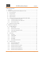
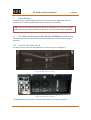
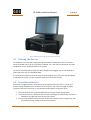
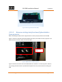
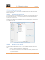
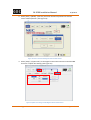
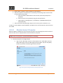
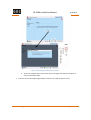
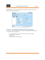
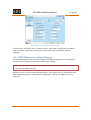
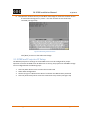
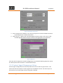
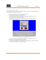
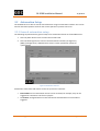
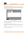
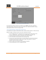
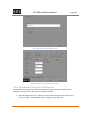
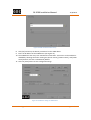
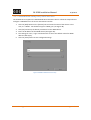
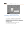
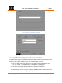
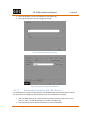
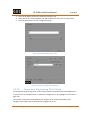
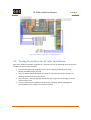
GDC Technology Ltd
SX-2000
SERVER INSTALLATION MANUAL
SX-2000 Installation Manual
11/8/2010
Table of Contents
1
Introduction ........................................................................................................................ 3
2
SX-2000 and Integrated Media Block (IMB) physical setup ................................................... 3
2.1
Server Presentation ..................................................................................................... 3
2.2
Placing the Server ........................................................................................................ 4
2.3
Insertion of Drives........................................................................................................ 4
2.4
Cable connections........................................................................................................ 5
2.5
Installing and connecting the GDC Integrated Media Block (IMB) ................................. 6
2.5.1
Installing the IMB into the projector ..................................................................... 6
2.5.2
Connecting the IMB to the SX-2000 server ........................................................... 9
2.5.3
Series 2 Projector Setup ..................................................................................... 11
2.6
3
IMB 3D macro settings changes ................................................................................. 17
SX-2000 server configuration ............................................................................................. 18
3.1
SX-2000 configuration................................................................................................ 19
3.1.1
Server IP Setup ................................................................................................... 19
3.1.2
IMB and Projector IP Setup ................................................................................ 20
3.1.3
Content Ingest Management Setup .................................................................... 21
3.1.4
Time Zone Setup ................................................................................................ 26
3.2
Audio Setup ............................................................................................................... 27
3.2.1
USL ECI-60 .......................................................................................................... 27
3.2.2
Yamaha DA824 ................................................................................................... 27
3.2.3
USL DAX-602 ...................................................................................................... 27
3.2.4
Dolby DMA8 ....................................................................................................... 27
3.2.5
Dolby CP650 Sound Processor ............................................................................ 28
3.3
Automation Setup...................................................................................................... 29
3.3.1
General automation setup ................................................................................. 29
3.3.2
Automation Scheduling ...................................................................................... 31
3.3.3
Automation setup for server GPIO...................................................................... 31
3.3.4
Automation setup for projectors ........................................................................ 32
3.3.5
Automation setup for eCNA devices ................................................................... 33
3.3.6
Automation setup for JNIOR devices .................................................................. 35
GDC Technology Ltd.
Page 1 of 42
SX-2000 Installation Manual
11/8/2010
3.3.7
Automation setup for Christie ACT devices ......................................................... 36
3.3.8
Automation setup for Dolby CP650 devices ........................................................ 37
3.3.9
Automation setup for USL DAX devices .............................................................. 38
3.3.10
Automation setup for USL JSD devices................................................................ 39
3.3.11
Component Engineering TA-10 Setup ................................................................. 40
3.4
Testing Procedures for QC after Installation ............................................................... 41
GDC Technology Ltd.
Page 2 of 42
SX-2000 Installation Manual
1
11/8/2010
Introduction
This document is a guide through the process of setting up the SX-2000 server with the
projector, audio system and automation devices used in cinema theatres.
Note: The currently supported software version for SX-2000 server is 7.7b-rc17 or higher.
Older versions of the server software (7.7b-rc15, or 7.7b-rc16) are no longer supported.
2
SX-2000 and Integrated Media Block (IMB) physical setup
This section describes the physical setup of the SX-2000 server in order to ensure proper
operation.
2.1 Server Presentation
The front and rear panel of the SX-2000 server is shown in Figure 1 and Figure 2.
Figure 1 SX-2000 server front panel
Figure 2 SX-2000 server rear panel
The SX-2000 can be set up with an external touchscreen LCD, as shown in Figure 3.
GDC Technology Ltd.
Page 3 of 42
SX-2000 Installation Manual
11/8/2010
Figure 3 SX-2000 server with external touchscreen LCD
2.2 Placing the Server
The SX-2000 is a 4U unit that is designed to be mounted on standard 19” racks. The server is
usually mounted to the rack in the projector pedestal, but it can also be mounted to any other
standard 19” rack or simply placed on a flat surface.
The server should be mounted with all cables completely unplugged. The screws required to
mount the server are not supplied by GDC.
It is important to make sure that the server is secured tightly to the rack and is not susceptible
to vibrations or shocks. It is also important to place the server horizontally.
2.3 Insertion of Drives
Each server is shipped with the content hard drives separate from the server. The server’s
content storage hard disks are inserted into a hot swap bay. The content storage hard disks
must be inserted into the server (in any particular order) before starting the server.
1
2
3
Ensure that the server is powered off before inserting a content storage drive.
Use the keys that are included to open the door covering the hard drive bay. The door is
located on the right side of the server’s front panel.
Press the open button located on the front left side of each content storage drive. This
will release the grey handle on the front of the drive.
GDC Technology Ltd.
Page 4 of 42
SX-2000 Installation Manual
4
5
6
11/8/2010
Insert each drive into the hot swap bay while making sure that the grey handle remains
open:
Note: Each hard drive can be inserted into any drive slot. They do not need to be
placed in any particular order.
Once the content storage drive has been inserted, close the grey handle by pushing it
toward the HDD until it clicks. This will lock in the content storage drive.
Close and lock the door covering the hard drive bay.
2.4 Cable connections
Once the server has been placed in the desired location, the cables described below should be
attached (See Figure 4).
1. VGA cable used for connecting to external touch screen monitor
2. Power cables
3. Network connections
a. eth0 – Projector
b. eth1 – Management
4. USB slot used for connecting to external touch screen monitor
5. PCI-e cable
2
4
5
3b
3a
1
Figure 4 SX-2000 rear panel with cables attached
GDC Technology Ltd.
Page 5 of 42
SX-2000 Installation Manual
11/8/2010
2.5 Installing and connecting the GDC Integrated Media
Block (IMB)
Note: If the projector comes with the GDC IMB pre-installed, the instructions in Section 2.5.1
can be skipped. Refer to Section 2.5.2 to connect the PCI-e cable to the IMB on the projector
and to the SX-2000 server.
If the projector does not have the GDC IMB installed, follow the steps below to install the IMB
into the projector.
2.5.1 Installing the IMB into the projector
This section of the manual deals with installing the IMB into the Projector, and connecting the
PCI-e and network cables to the IMB and projector respectively.
2.5.1.1
IMB components
The GDC Integrated Media Block comes with a PCI-e cable (see Figure 5) for connecting to the
SX-2000 server. The IMB is shown in Figure 6.
Figure 5 PCI-e cable for GDC IMB
GDC Technology Ltd.
Page 6 of 42
SX-2000 Installation Manual
11/8/2010
Figure 6 GDC Integrated Media Block (IMB)
2.5.1.2
Remove existing interface board/placeholders
from projector
Before installing the IMB, check the figures below to ensure proper placement of the IMB.
Figure 7 shows an interface board (with SMPTE 292 inputs) connected to a Barco projector. This
board must be removed in order to install the IMB.
Remove for
IMB
Figure 7 IMB Placement on Barco projectors
Figure 8 shows the location where the IMB should be installed on a Christie projector. Remove
any existing interface boards or placeholder faceplates from this position before installing the
IMB.
GDC Technology Ltd.
Page 7 of 42
SX-2000 Installation Manual
11/8/2010
IMB
installed
here
Figure 8 IMB placement on Christie projectors
Figure 9 shows the location where the IMB should be installed on a NEC projector. Remove any
existing interface boards or placeholder faceplates from this position before installing the IMB.
IMB
installed
here
Figure 9 IMB placement on NEC projectors
Please refer to the projector manuals for more details on preparing the projector for IMB
installation.
2.5.1.3
Inserting IMB to the Projector
Make sure the projector is powered off before installing the IMB on the projector.
GDC Technology Ltd.
Page 8 of 42
SX-2000 Installation Manual
11/8/2010
Figure 10 Inserting the IMB into the projector
Insert the IMB as shown in Figure 10.
The IMB should slide into the projector on the rails provided by the IMB slot, and the IMB
faceplate should be flush with the other existing faceplates once properly inserted.
2.5.2 Connecting the IMB to the SX-2000 server
The IMB on the projector and the SX-2000 server must be connected for proper operation.
There are two cables to be connected between the projector and the SX-2000 server:
•
•
CAT-5E network cable to connect the network between the projector and the server.
The projector and server can also be connected through a network switch.
PCI-e cable for connecting the IMB installed on the projector and to PCI-e slot on the
server back panel.
The PCI-e cable has a square metal connector and a green circular plastic tab located on each
end. The green tab is used to release the PCI-e connection. To insert the PCI-e cable into the IMB
or server, push the PCI-e cable connector firmly into the respective to the PCI-e slot. To release
this cable from the PCI-e slot on the server or IMB, pull on the green tab until the cable is
removed.
GDC Technology Ltd.
Page 9 of 42
SX-2000 Installation Manual
2.5.2.1
11/8/2010
Connecting to the IMB and the projector
Connect the PCI-e cable and the network cable as shown in Figure 11.
Figure 11 Connecting cables on the projector
2.5.2.2
Connecting to the SX-2000 server
Connect the PCI-e cable and the network cables as shown in Figure 12.
Figure 12 Connecting cables on the SX-2000 server
GDC Technology Ltd.
Page 10 of 42
SX-2000 Installation Manual
11/8/2010
2.5.3 Series 2 projector setup
To work with the GDC IMB, the projector must be set up according to the requirements of the
projector manufacturer.
2.5.3.1
Barco Series 2 Projector
No system configuration is required for Barco Series 2 projector to work with the GDC IMB. The
Service Door/Marriage Tamper on the server must be cleared before the IMB can be used for
playback (refer to Section 3.1.2).
In order to use the IMB for content playback, the INPUT source of the projector macros must be
set to IMB (See Figure 13).
Figure 13 INPUT source settings on Barco Series 2 projector
2.5.3.2
NEC Series 2 Projector
In order to configure an NEC Series 2 projector to work with IMB, the following steps must be
taken:
1. Switch on the projector so that it is in STANDBY mode.
2. Use the Digital Cinema Communicator for S2 Windows software provided by NEC to
connect to the projector.
GDC Technology Ltd.
Page 11 of 42
SX-2000 Installation Manual
11/8/2010
3. Select [Start] ->[Mode] ->[Service] and enter the Service password to activate
service mode operation. (See Figure 14)
Figure 14 Service mode on NEC Digital Cinema Communicator
4. Select [Setup] ->[Option Slot] on the Digital Cinema Communicator and select IMB
for Slot A in Option Slot Setting. (See Figure 15)
Figure 15 Option slot settings on NEC Digital Cinema Communicator
GDC Technology Ltd.
Page 12 of 42
SX-2000 Installation Manual
11/8/2010
5. Select [Start] ->[Power] ->[On] to power on the projector.
6. After the projector has powered on successfully, the following steps must be taken
at the projector front panel:
a. Press and hold the Menu button until the front panel LCD prompts for a
password
b. Enter the Service user password using the channel buttons.
c. Select [Menu]->[Configuration] ->[Installation] ->[NewRouterSetup] and
select [Execute].
7. Clear the Service Door/Marriage Tamper on the server (refer to Section 3.1.2).
In order to use the IMB for content playback, the INPUT source of the projector macros must be
set to IMB.
2.5.3.3
Christie Series 2 Projector
When the IMB is installed into a Christie Series 2 projector, the following steps must be taken in
order for GDC server to playback with the Christie Series 2 projector:
Note: Ensure the projector is powered ON before proceeding.
1. Clear the projector’s marriage tamper:
a. Log in to the "Marriage" account on the projector TPC. Select Menu->Service
Setup->Marriage to start the Marriage wizard (see Figure 16). Click the [Next]
button to proceed to the Marriage Checklist window.
Figure 16 Projector marriage wizard on Christie projector TPC
GDC Technology Ltd.
Page 13 of 42
SX-2000 Installation Manual
11/8/2010
b. Read and perform the actions listed in the Marriage Checklist. In the Marriage
Checklist window (see Figure 17), the system checks that all tamper switches are
secure and lists items that you must check to ensure the projector is secure
before proceeding. Click the [Next] button to proceed to the Arming window.
Figure 17 Marriage checklist
c. Arm the marriage. In the Arming window, click the Arm Marriage button (refer
to Figure 18). A 30 second count-down timer begins. The LED in the Marriage
button on the PI Board will flash green during this count-down. You MUST press
the Marriage button on the PI Board within this 30 second window in order for
the marriage to take effect. When the Marriage button is pressed, the LED
button will change to a solid green to indicate a successful marriage.
GDC Technology Ltd.
Page 14 of 42
SX-2000 Installation Manual
11/8/2010
Figure 18 Arm Marriage and Marriage countdown
d. The Finish window states the success of the marriage. Click the Finish button to
return to the Main panel.
2. Clear the Service Door/Marriage Tamper on the server (refer to Section 3.1.2).
GDC Technology Ltd.
Page 15 of 42
SX-2000 Installation Manual
11/8/2010
All 3D IMB channels on the Christie Series 2 projector should use the ‘IMB’ input and ‘4:4:4
(RGB)’ input data format (see Figure 19).
Figure 19 Projector input settings for Christie projectors
2.5.3.3.1 3D settings for Christie Series 2 projectors
The 3D macros for Christie Series 2 projectors should be configured with the following settings
for ‘3D Input Control’ (see Figure 20):
•
•
•
•
3D Sync Input Mode: Use ‘Line Interleave’ (first line=Left, second line=Right)
L/R Display Reference: Not Used
Frame Rate: 6:2
L/R Display Sequence: Left (L1R1 L2R2)
GDC Technology Ltd.
Page 16 of 42
SX-2000 Installation Manual
11/8/2010
Figure 20 3D macro settings for Christie projectors
The settings for 3D output control ( ‘3D Sync Polarity’, ‘Dark Time’, ‘Output Delay’ and ‘Phase
Delay’) should be customized according to the type of 3D system used (RealD, XpanD or
Dolby3D).
2.6 IMB 3D macro settings changes
Server software version 7.7b-rc17 makes changes to the IMB 3D output format. The following
projector macro changes are required to support these changes.
Note: These are required changes on the projector. IMB 3D output will not function properly
unless these changes are made.
Software version 7.7b-rc17 enables IMB 3D output in ‘4:4:4’ format. This can be enabled on the
SMS configuration page, by selecting SMS->Configuration ->CineCanvas->IMB 3D 4:4:4 (see
Figure 21).
GDC Technology Ltd.
Page 17 of 42
SX-2000 Installation Manual
11/8/2010
Figure 21 IMB 3D 4:4:4 configuration on SX-2000 server
2.6.1.1
NEC Series 2 projectors
The IMB 3D macros on existing NEC Series 2 projectors are configured for ‘4:2:2’ input.
If the ‘IMB 3D 4:4:4’ option is checked in SMS configuration, all IMB 3D macros should be
changed to use ‘4:4:4’ input.
2.6.1.2
Barco Series 2 projectors
The IMB 3D macros on existing Barco S2 projectors are configured to use the
‘GDC_IMB_422.input’ file.
If the ‘IMB 3D 4:4:4’ option is checked in SMS configuration, all IMB 3D macros should use the
input file named ‘Mediablock.input’.
2.6.1.3
Christie Series 2 projectors
The ‘IMB 3D 4:4:4’ option in SMS configuration must be checked.
No additional configuration is required for the projector.
3
SX-2000 server configuration
This section describes the steps necessary to set up the SX-2000 and configure it to work with
supported cinema equipment.
GDC Technology Ltd.
Page 18 of 42
SX-2000 Installation Manual
11/8/2010
3.1 SX-2000 configuration
Note: The Series 2 projector has to be booted up and ready first before SX-2000A is powered
on. The indication of Series 2 projector being ready is that the three LED lights (OS, FMT, ICP)
should be constantly green and the LED light (SOFT) should be blinking green.
3.1.1 Server IP Setup
The IP address of the two network interface cards (NIC) on the SX-2000 server needs to be set
for proper operation. When configuring the NICs please keep in mind that eth0 is used for
projector communication and eth1 is used for the media network.
1
2
3
4
5
Click the power button once to access the [Control Panel]. You can also access the
Control Panel by selecting the [Control Panel] button from the SMS.
Click [Admin Panel] to access the Admin Panel Page.
Click [Focus] at the far bottom right of the keyboard, then click the cursor in the
“Password” text box to enter the password.
Select [Network]->[Network Setup]. This opens up a page displaying the Ethernet
connections of the two NICs. (eth0 is used to communicate with the projector and
eth1 is used for network access)
Highlight the NIC you wish to configure and click [Select] to view and change the
network configuration settings for this NIC. In this case, the NIC eth0 was chosen
(See Figure 22)
Figure 22 Network settings for eth0
6
7
Once the settings have been entered, click [OK] and a small window will appear to
prompt you to “Restart network service”. Click [OK] to confirm.
Repeat steps 5 and 6 to configure the other NIC.
GDC Technology Ltd.
Page 19 of 42
SX-2000 Installation Manual
8
11/8/2010
Click [Restart network service] on the Admin Panel Page to restart the network service.
A confirmation dialog will say “Done.” once the network services have been
restarted (see Figure 23)
Figure 23 Restarting network services
Click [Back] to return to the Admin Panel Page.
3.1.2 IMB and Projector IP Setup
The IMB and projector IP settings on the SX-2000 server must be configured for proper
operation. Once the SX-2000 server IP addresses are set up, the projector IP and IMB marriage
can be configured with the following steps:
1
2
3
4
Click the power button once to access the Control Panel
Select SMS->Configuration
Choose to log in as “Maintenance Access” and enter the Maintenance password
Click the [CineCanvas] tab to access the CineCanvas setup screen (see Figure 24)
GDC Technology Ltd.
Page 20 of 42
SX-2000 Installation Manual
11/8/2010
Figure 24 Cinecanvas setup screen
5
6
Enter the projector IP address in the “Primary Projector IP” field and enable CineCanvas
by checking the box “Enable CineCanvas”.
Select General -> IMB to check the Marriage/Service door tamper. Click Clear to clear
the Marriage/Service door tamper if a failure message appears (see Figure 25)
Figure 25 IMB status
Once the IP for the projector has been configured you can proceed to defining projector macros.
For details please refer to Section 2.1.5 Automation Setup.
3.1.3 Content Ingest Management Setup
Content ingest management must be set up before the server is able to ingest content. This
section will show the setup for content ingest from two different sources. The same steps can
be used to set up content ingest sources using other methods.
GDC Technology Ltd.
Page 21 of 42
SX-2000 Installation Manual
3.1.3.1
11/8/2010
Content ingest from USB disk
The following steps describe the setup of a content ingest source for ingesting content from an
external USB hard drive:
1. Click the power button once to access the Control Panel.
2. Click [Manage Content] to access the Content Management Page.
3. Click the [Source] tab, followed by the [Add] button. This opens up the Source Setup
Page (see Figure 26).
Figure 26 Content manager source setup page
4. Enter the name of the source in the “Source Name...” text box. In this example, we will
be setting up a USB source and naming it “USB” (See Figure 27). Select “USB 2.0” as the
Source Type.
GDC Technology Ltd.
Page 22 of 42
SX-2000 Installation Manual
11/8/2010
Figure 27 USB ingest source setup
5. Click [Save] to save the settings for the USB content ingest source.
3.1.3.2
Content ingest from FTP
The following steps describe the setup of a content ingest source for ingesting content from an
FTP server:
1. Select the [Source] tab, followed by the [Add] button (see Figure 26).
2. Enter the local description for the FTP server in the “Source Name…” text box. In this
case, we will use the source name “FTP”. Select “FTP” as the Source Type.
Figure 28 FTP ingest source setup
GDC Technology Ltd.
Page 23 of 42
SX-2000 Installation Manual
11/8/2010
3. Enter the respective parameters for Source IP, Source Path, Username and Password
(see Figure 28).
4. Click [Save] to save the settings for the FTP content ingest source.
GDC Technology Ltd.
Page 24 of 42
SX-2000 Installation Manual
3.1.3.3
11/8/2010
Selecting an ingest source
To select an ingest source, click
next to the “Source to ingest from:” label on the “Ingest” tab.
Choose the required ingest source from the drop down menu. (See Figure 29)
Figure 29 Ingest from USB source
GDC Technology Ltd.
Page 25 of 42
SX-2000 Installation Manual
11/8/2010
3.1.4 Time Zone Setup
The SX-2000 server may or may not arrive with the local time zone set. The following steps show
how to change the time zone on the server.
1. Click the power button once to access the Control Panel.
2. Click [Admin Panel] to access the Admin Panel.
3. Click [Focus] at the far bottom right of the keyboard, then click the cursor in the
“Password” text box to enter the password.
4. Click [Diagnostics/Maintenance]->[Configure Timezone] to access the Time zone
Selection Page (see Figure 40)
Figure 30 Timezone configuration
5. Click [Focus] and tap the section above the keypad to bring the pointer into focus.
6. Use [↑] and [↓] to highlight the desired timezone.
7. Click [Tab] until the [OK] button is highlighted and click [Return] to set the timezone (Do
not change the “System clock uses UTC” setting).
GDC Technology Ltd.
Page 26 of 42
SX-2000 Installation Manual
11/8/2010
3.2 Audio Setup
Not every case will require a Digital-to-Analog Converter (DAC) as some sound processors are
able to receive digital input. In the case that a DAC is required the first thing that should be
done is to connect the server to the DAC. This device converts the digital audio signal to an
analog audio signal. The DAC is then connected to a sound processor that processes the analog
audio signal and outputs it to the amplifier, and subsequently the cinema’s speakers.
The following sections document the installation instructions for the server with some of the
popular DACs and sound processors.
3.2.1 USL ECI-60
Since the USL ECI-60 has a digital input channel, the audio output of the server can be
connected directly to the ECI-60 using a 25-pin D-Sub cable.
1. Connect one end of the 25-pin D-Sub audio cable to the audio output on the server.
2. Connect the other end of the audio cable into the input labeled “AES 8 Ch Input” on the
USL ECI-60.
3.2.2 Yamaha DA824
There are several ways in which the Yahama DA824 can be configured with the server. The
simplest configuration is the straight through AES/EBU Connection. This again uses the 25-pin
D-Sub cable.
1. Connect one end of the 25 pin D-Sub audio cable to the audio output on the server.
2. Connect the other end of the audio cable into the input labeled “AES 8 Ch Input” on the
Yamaha DA824.
3.2.3 USL DAX-602
The USL DAX-602 has a direct AES-EBU Digital Input as well. The audio output of the server can
be connected directly using the 25-pin D-Sub cable.
1. Connect one end of the 25-pin D-Sub audio cable to the audio output on the server.
2. Connect the other end of the audio cable into the input labeled “AES-EBU Digital In” on
the USL DAX-602.
3.2.4 Dolby DMA8
The Dolby DMA8 has a direct input for AES digital input. The audio output of the server can be
connected directly using the 25 D-Sub Cable.
1. Connect one end of the 25 pin D-Sub audio cable to the audio output on the server.
GDC Technology Ltd.
Page 27 of 42
SX-2000 Installation Manual
11/8/2010
2. Connect the other end of the audio cable into the input labeled “4x AES In (Digital 8 ch)”
on the Dolby DMA8.
3.2.5 Dolby CP650 Sound Processor
The Dolby CP650 requires an optional board to be used (650-OPTIO-AES). Once installed the
optional 650 OPTIO-AES board will enable 25-pin D-Sub digital input to the Dolby CP650.
To install the board, insert it into the Option I/O Connection on the back of the CP650. Please
refer to the Dolby CP650 manual for more information on installing the 650-OPTIO-AES board.
The board will have two connectors. The one at the top will be the 4xAES connector (this
connector emulates the 4xAES connector on the DMA8).
1. Connect one end of the 25 pin D-Sub audio cable to the audio output on the server.
2. Connect the other end of the audio cable to the top 4xAES connector on the OPTIO-AES
board on CP650.
GDC Technology Ltd.
Page 28 of 42
SX-2000 Installation Manual
11/8/2010
3.3 Automation Setup
The SX-2000 server is able to control external devices using its automation interface. This can be
used to automate repetitive tasks for the cinema operator to prevent user error.
3.3.1 General automation setup
The following steps describe the general setup of an automation device on the SX-2000 server.
1. Click the power button once to access the Control Panel.
2. Click the following buttons to access the Automation interface (see Figure 31)
[SMS]->[Configuration]->[Maintenance Access]->(enter password)->[General]>[Automation]
Figure 31 Automation interface
Automation event labels and actions can be set up from this interface:
•
•
Event Labels are how automation actions can be accessed, for example, they can be
triggered as automation cues from an playlist
The Actions configured with an event label will be executed when an event label is
triggered.
GDC Technology Ltd.
Page 29 of 42
SX-2000 Installation Manual
11/8/2010
3.3.2 Adding event labels and actions
The following steps describe how to add an event label to the automation interface. This
automation label is used to trigger the associated automation actions during playback.
1
3
2
5
1. Click the [Add] button next to the ‘Event Label’ menu to add a new event label. Enter
the name of the event label.
2. Click the [Add] button below the table to add a new action associated with this event
label.
3. A new action is added to the table. The ‘Device’ and ‘Action’ settings of this new action
can be changed. Notice that when the ‘Device’ setting is changed, the possible ‘Action’
settings for that device are displayed. Refer to the following sections on adding
automation devices.
4. Repeat steps 2 and 3 to add more actions to this event label. Use the [Delete] button
below the table to remove the last action added to the list.
5. You can test the event label and the list of actions associated with the event label by
clicking the [Execute] button.
GDC Technology Ltd.
Page 30 of 42
SX-2000 Installation Manual
11/8/2010
3.3.3 Automation Scheduling
Automation event labels can be scheduled to be executed at a pre-arranged date and time, or
repeated daily at a pre-arranged time. To access the automation schedule select the [Schedule]
button on the [Actions] tab on the automation interface. This will bring you the automation
schedule configuration screen (see Figure 32).
Figure 32 Schedule automation events
To add a scheduled automation event, select the [Add] button. Set the date and time of the
automation event, the repeat interval, and the event label to be executed. Click [Accept
Changes] to save created schedules.
3.3.4 Automation setup for server GPIO
If the SX-2000 server has a GPIO card installed, the ‘GPIO’ automation device will be available
for configuration. It is not possible to add a ‘GPIO’ automation device if the GPIO card is not
installed.
The GPIO automation device settings can be configured from the [Devices] tab after selecting
the ‘GPIO’ device name (see Figure 33).
GDC Technology Ltd.
Page 31 of 42
SX-2000 Installation Manual
11/8/2010
Figure 33 GPIO automation device settings
If the output pulse width is left blank, the default value of 50ms will be used. If a different
output pulse width is required, the value can be entered in the ‘Output Pulse Width’ setting.
Click the [Save] button to save any changes made.
3.3.5 Automation setup for projectors
The SX-2000 server supports automation for Barco, Christie and NEC projectors. Follow the steps
below to configure a projector device in the server automation interface.
1. Click the [Add] button on the [Devices] tab and enter the name of the device. In this
case, it is “PROJECTOR”. Set the device type to “PROJECTOR” (see Figure 34).
2. Click [OK] and set up the device parameters for the projector device.
3. Enter the IP address of the projector device (see Figure 35).
4. Set the correct model of the projector. The port number will automatically change to
the default automation port number for the model. If the projector is a Series 2
projector, check the ‘Series 2’ checkbox.
5. Enter the ‘Login’ and ‘Password’ for the projector if required.
6. Click the [Save] button to save configured settings.
GDC Technology Ltd.
Page 32 of 42
SX-2000 Installation Manual
11/8/2010
Figure 34 Projector automation device setup
Figure 35 Automation settings for projector device
3.3.6 Automation setup for eCNA devices
The SX-2000 server supports the eCNA-10 automation system. Follow the steps below to
configure an eCNA device in the server automation interface.
7. Click the [Add] button on the [Devices] tab and enter the name of the device. In this
case, it is “eCNA”. Set the device type to “eCNA_IO” (see Figure 36).
GDC Technology Ltd.
Page 33 of 42
SX-2000 Installation Manual
11/8/2010
Figure 36 eCNA automation device setup
8. Click [OK] and set up the device parameters for the eCNA device.
9. Enter the IP address of the eCNA device (see Figure 37).
10. The eCNA device has many cues available for automation. These cues can be enabled or
disabled by selecting them after clicking the [Server events], [eCNA controls], and [eCNA
status] buttons. All cues are disabled by default.
11. Click the [Save] button to save configured settings.
Figure 37 Automation settings for eCNA device
GDC Technology Ltd.
Page 34 of 42
SX-2000 Installation Manual
11/8/2010
3.3.7 Automation setup for JNIOR devices
The SX-2000 server supports the JNIOR Model 310 automation device. Follow the steps below to
configure a JNIOR device in the server automation interface.
1. Click the [Add] button on the [Devices] tab and enter the name of the device. In this
case, it is “JNIOR”. Set the device type to “JNIOR_IO” (see Figure 38).
2. Click [OK] and set up the device parameters for the JNIOR device.
3. Enter the IP address of the JNIOR device (see Figure 39).
4. The settings for ‘Port’, ‘Login’ and ‘Password’ are set to the default values for JNIOR
devices if left empty.
5. Click the [Save] button to save configured settings.
Figure 38 JNIOR automation device setup
GDC Technology Ltd.
Page 35 of 42
SX-2000 Installation Manual
11/8/2010
Figure 39 Automation settings for JNIOR device
3.3.8 Automation setup for Christie ACT devices
The SX-2000 server supports Christie ACT automation device. Follow the steps below to
configure a Christie ACT device in the server automation interface.
1. Click the [Add] button on the [Devices] tab and enter the name of the device. In this
case, it is “ChristieACT”. Set the device type to “ChristieACT” (see Figure 40).
2. Click [OK] and set up the device parameters for the Christie ACT device.
3. Enter the IP address of the Christie ACT device (see Figure 41).
4. The default setting for the ‘Port’ is displayed on the settings for the Christie ACT device.
Change this value if required.
5. Default control cues will be set up for a new Christie ACT automation device. Control
cues can be added or removed by clicking on the [+] and [-] buttons.
6. Click the [Save] button to save configured settings.
GDC Technology Ltd.
Page 36 of 42
SX-2000 Installation Manual
11/8/2010
Figure 40 Christie ACT automation device setup
Figure 41 Automation settings for Christie ACT device
3.3.9 Automation setup for Dolby CP650 devices
The SX-2000 server supports automation for the Dolby CP650 sound processor. Follow the steps
below to configure a Dolby CP650 device in the server automation interface.
1. Click the [Add] button on the [Devices] tab and enter the name of the device. In this
case, it is “CP650”. Set the device type to “DolbyCP650” (see Figure 42).
2. Click [OK] and set up the device parameters for the Dolby CP650 device.
3. Enter the IP address of the Dolby CP650 device (see Figure 43).
4. Default Control cues are set up for a new Dolby CP650 automation device. Control cues
can be added or removed using the [+] and [-] buttons.
GDC Technology Ltd.
Page 37 of 42
SX-2000 Installation Manual
11/8/2010
5. Click the [Save] button to save configured settings.
Figure 42 Dolby CP650 automation device setup
Figure 43 Automation settings for Dolby CP650 device
3.3.10
Automation setup for USL DAX devices
The SX-2000 server supports automation for USL DAX sound processor. Follow the steps below
to configure a USL DAX device in the server automation interface.
1. Click the [Add] button on the [Devices] tab and enter the name of the device. In this
case, it is “DAX”. Set the device type to “USL-DAX” (see Figure 44).
2. Click [OK] and set up the device parameters for the USL DAX device.
GDC Technology Ltd.
Page 38 of 42
SX-2000 Installation Manual
11/8/2010
3. Enter the IP address of the USL DAX device (see Figure 45).
4. Click the [Save] button to save configured settings.
Figure 44 USL DAX automation device setup
Figure 45 Automation settings for USL DAX device
3.3.11
Automation setup for USL JSD devices
The SX-2000 server supports automation for USL JSD-80 and JSD-100 sound processor. Follow
the steps below to configure a USL JSD device in the server automation interface.
1. Click the [Add] button on the [Devices] tab and enter the name of the device. In this
case, it is “JSD”. Set the device type to “USL-JSD” (see Figure 46).
2. Click [OK] and set up the device parameters for the USL JSD device.
GDC Technology Ltd.
Page 39 of 42
SX-2000 Installation Manual
11/8/2010
3. Enter the IP address of the USL JSD device (see Figure 47).
4. Select the correct model (JSD-80 or JSD-100) of the device the server is connected to.
5. Click the [Save] button to save configured settings.
Figure 46 USL JSD automation device setup
Figure 47 Automation settings for USL JSD device
3.3.12
Component Engineering TA-10 Setup
The Component Engineering TA-10 can be used for theater automation with the SX-2000 server.
It requires that the TA-10 be wired in a particular configuration. A wiring diagram can be seen in
Figure 48.
The TA-10 is connected to the SX-2000 server using the server’s GPIO input/output port.
Configure event labels with the GPIO device to trigger the TA-10.
GDC Technology Ltd.
Page 40 of 42
SX-2000 Installation Manual
11/8/2010
Figure 48 Component Engineering TA-10 wiring diagram
3.4 Testing Procedures for QC after Installation
After the installation has been completed, it is necessary to test the following to ensure that the
SX-2000 has been properly installed:
1. Test the video playback capabilities of the server using the following file formats:
MPEG2, JPEG2000, Scope, Flat, 3D.
2. Test the audio playback capabilities of the server and verify that all the channels are
working. Also check for any static noises.
3. Test the server’s ability to activate automation cues using test cues for lights, curtains,
sound and fire alarm.
4. Test the remote access capabilities of the server, including: Theater Management
System (TMS) access, network connectivity and VNC.
GDC Technology Ltd.
Page 41 of 42