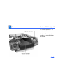
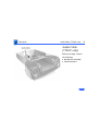
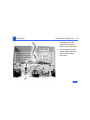
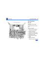
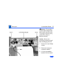
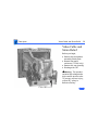
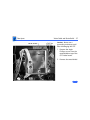
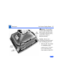
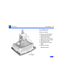
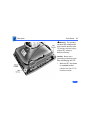
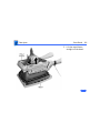
1
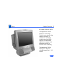
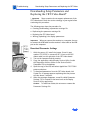
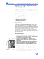
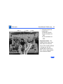
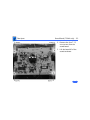
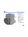
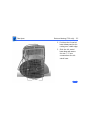
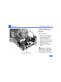
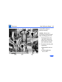
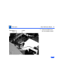
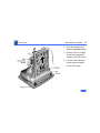
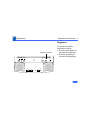
K Service Source
17" ColorSync Displays
17” ColorSync Display (was AppleVision 750)
17” ColorSync AV Display (was AppleVision 750AV)
K Service Source
Hot Issues
17" ColorSync Displays
(AppleVision 750, 750AV)
Hot Issues
Overview - 1
Overview
This chapter is designed to highlight unique or highpriority product issues that you should be aware of before
servicing this display.
This chapter alerts you to important issues and provides
links to other areas in the manual where more complete
information can be found. This chapter is not intended to
replace other parts of this manual; it merely provides a
pointer to pertinent information in those chapters.
The date the Hot Issue was published is indicated in
parentheses after the title.
Hot Issues
Revised Troubleshooting Chapter Features CRT/Video Board Pro-
Revised Troubleshooting Chapter
Features CRT/Video Board Procedures
(3/98)
The Troubleshooting chapter has been revised to include
procedures for downloading setup parameters, adjusting the
display after replacing the CRT/video board or the main
deflection board, and diagnosing suspected hardware
problems.
The latest version of the Diagnostics utility called Display
Service Utility (v4.2.1) enables service providers to more
accurately determine the source of hardware problems and
readily repair the display.
The CRT/video board (Apple part number 661-1373) is
now offered worldwide as a replacement module. Refer to the
Hot Issues
Revised Troubleshooting Chapter Features CRT/Video Board Proexpanded Troubleshooting chapter for the latest
troubleshooting procedures; refer to the Diagnostics site of
Service Source Online or the Service Source Companion CD
(Diagnostic Utilities folder) for the Display Service Utility
v4.2.1.
Hot Issues
Jittery or Blurry Video with Power Macintosh 5500/6500
Jittery or Blurry Video with Power
Macintosh 5500/6500 (12/97)
If the display exhibits jittery or blurry video when
connected to a Power Macintosh 5500 or 6500, suspect the
computer, not the monitor.
Video jitter affects monitors connected to computers having
a 225 or 250 MHz logic board. Jitter is evident where the
pixels shimmer or jump at the edges of the screen, windows,
or dialog boxes.
Blurry video is seen as a fuzzy image over the entire screen
on monitors set to resolutions of 832x624 and higher.
Hot Issues
Jittery or Blurry Video with Power Macintosh 5500/6500
Identifying Suspect Units
Video jitter or blurry video can be caused by Power
Macintosh computers within the following serial number
ranges.
Video Jitter
• PM 5500 from TY705xxxxx to TY715xxxxx
• PM 6500 from XB708xxxxx to XB718xxxxx
Blurry Video
• PM 6500 from XB708xxxxx to XB723xxxxx
The system software on Power Macintosh 6500 computers
allows selecting monitor resolutions above 1152x870. But
these higher resolutions are not supported and cause poor
video output, such as misaligned or skewed video, low
brightness, blurriness, and so on. Monitors connected to
Hot Issues
Jittery or Blurry Video with Power Macintosh 5500/6500
Power Macintosh 6500 computers should not be set to
resolutions higher than 1152x870.
Check the Monitors & Sound control panel to make sure the
resolution is set to 1152x870 or lower. For a chart of
supported monitor resolutions for the Power Macintosh
6500, see the Specifications chapter in the Performa/
Power Macintosh 6400 and 6500 Series manual on Service
Source.
Although these symptoms have never been reported for a
Power Macintosh 5500, the 225 MHz logic board used in the
Power Macintosh 6500 is also used in the 5500. Refer to
the Troubleshooting chapter in Service Source for both
Power Macintosh manuals.
K Service Source
Basics
17" ColorSync Displays
(AppleVision 750, 750AV)
Basics
Product Name Change - 1
Product Name Change
The AppleVision 750 and 750AV Displays were renamed in
November, 1997.
Original Name
AppleVision 750 Display
AppleVision 750AV Display
New Name
17” (16.1” VIS) ColorSync Display
17” (16.1” VIS) ColorSync AV Display
Although the body of this service manual retains the
AppleVision names, both names are shown on the title page of
each chapter. The ColorSync name change was the only
change to the product.
Note: VIS represents the diagonal viewable image size of the
display.
Basics
Product Overview - 2
Product Overview
The AppleVision 750AV
Display is a full-page,
Trinitron color monitor that
supports a variety of
resolutions. The display
includes sound and video
support for multimedia
application programs and
advanced controls for
accurate color rendering.
The AppleVision 750AV
Display has a diagonal
viewable image size of 16.1
inches.
Basics
Product Overview - 3
The AppleVision 750AV Display works with both Mac OSbased and Windows-based computers.
Features
The AppleVision 750AV Display features
• A wide range of screen resolutions (from 640x480 to
1280x1024)
• A tilt/swivel base that allows the monitor to be
positioned for optimal viewing comfort
• Integrated speaker enclosure and voice recognitioncapable microphone
• Energy Star Power Conservation compliance
• TCO 92 compliance
Except for the speaker enclosure and microphone, the
AppleVision 750 Display shares the same features as the
AppleVision 750AV Display.
Basics
Repair Issue: Display Service Utility - 4
Repair Issue:
Display Service
Utility
The Display Service Utility
(on the Service Source
Companion CD: Diagnostic
Utilities folder) is an
application that you can use
to display video test
patterns, run some
troubleshooting
procedures, and adjust
geometry.
Basics
Repair Issue: Display Service Utility - 5
A selection for the
AppleVision 750/750AV
was added to the latest
version of the Display
Service Utility on the
Service Source Companion
CD and Service Source
Online. Within the Display
Service Utility, select
Pattern Selections:
AppleVision 750/750AV,
and click the Adjust
Geometry button.
Clicking the Adjust
Geometry button opens a
screen of scroll bars that
you can use to make various
Basics
Repair Issue: Display Service Utility - 6
geometry adjustments. Although most of these adjustments
can be duplicated by using the Monitors & Sound control
panel, high voltage can only be adjusted with the Display
Service Utility.
Refer to the Read Me document in the Display Service Utility
folder for more information.
For more information on using the Display Service Utility
for troubleshooting or adjusting the AppleVision 750 and
750AV displays, refer to the Troubleshooting chapter in this
manual.
Basics
Repair Issue: TCO 95 Housing - 7
Repair Issue: TCO 95 Housing
Effective January 1998, TCO 95 plastics are used for the
17” ColorSync Display (but not the AV version). The higher
environmental rating of plastics is used for the following
housing parts:
• 076-0723 ADB Board Panel, TCO 95
• 922-3335 Front Bezel, TCO 95
• 922-3338 Rear Housing, TCO 95
• 922-3343 Bottom Housing, TCO 95
• 922-3387 Blank Plate, TCO 95
Important: ColorSync displays using TCO 95 plastics can be
identified by the TCO 95 marking on the back of the rear
housing. Replace TCO 95 housing parts like-for-like. Do not
substitute with TCO 92 parts.
K Service Source
Specifications
17" ColorSync Displays
(AppleVision 750, 750AV)
Specifications
Introduction - 1
Introduction
Specifications information for this product can be found in this
chapter and also in the Spec Database, which you can access in one
of three ways:
• Launch it directly by double-clicking the Apple Spec Database
runtime alias at the top level of the Main Service Source CD.
• Select “Apple Spec Database” from the Service Source dropdown main menu.
• Click the Acrobat toolbar icon for the database, which is near
the right end of the toolbar with the letters “SP.”
Specifications
Characteristics - 2
Characteristics
Picture Tube
Screen Resolution
17-in. Trinitron CRT (16.1-in. diagonal viewable image)
Multiple scan, antistatic, antiglare surface treatment
0.26-mm stripe pitch
640x480 at 60 Hz in VGA mode
640x480 at 66.67 Hz in Macintosh mode
800x600 at 60.31 Hz in VESA mode
800x600 at 75 Hz in VESA mode
832x624 at 74.55 Hz in Macintosh mode
1024x768 at 74.93 Hz in Macintosh mode
1024x768 at 60 Hz in VESA mode
1152x870 at 75 Hz in Macintosh mode
1280x1024 at 60 Hz in VESA mode
1280x1024 at 75.03 Hz in VESA mode
Specifications
Characteristics - 3
Scan Rates
Vertical refresh rate: 40–120 Hz
Horizontal scan rate: 30–80 kHz
Cable Connector
15-pin miniature D-type
Input Signals
Red, green, and blue signals; separate sync
Specifications
System Requirements
Characteristics - 4
System software version 7.1 or later
Computers with 68040 microprocessors or later
AppleVision software is supported by the following computers:
PCI CPUs: 7200, 7500, 7600, 8500, 9500, 6360, 6400,
6500, 7300, 8600, 9600 or later CPUs
PowerMac CPUs: 8100/100, 8100/80AV, 7100/80, 6100/
66, 6100/60AV, 6200, 6300
PowerBooks: 280c & 2300/Mini Dock/Duo Dock II, 540c,
5300, 1400, and 3400
Quadra CPUs: Q605, Q610, Q630, Q630/PowerMac Upgrade,
C650, Q650, Q650/STP, Q950, Q950/STP, 660AV, 840AV
Apple DOS-compatible CPUs: Q610/DOS, 6100/DOS, 640
DOS, PC-compatible Pentium 100 MHz and 586 Pentium
100 MHz PC cards on PCI CPUs.
Specifications
Monitor Timings
Characteristics - 5
640x480
Resolution @ 60 Hz
640x480
Resolution @ 66.67 Hz
Horizontal Timing
1/H: 31.5 kHz
Back Porch: 48 dots
H SYNC: 96 dots
Front Porch: 16 dots
1 H: 31.75 µs
1/dot: 25.175 MHz
Horizontal Timing
1/H: 34.97 kHz
Back Porch: 96 dots
H SYNC: 64 dots
Front Porch: 64 dots
1 H: 28.0 µs
1/dot: 30.24 MHz
Vertical Timing
1 V: 16.7 ms
Back Porch: 33 H
V SYNC: 2 H
Front Porch: 10 H
Vertical Timing
1 V: 15.0 ms
Back Porch: 39 H
V SYNC: 3 H
Front Porch: 3 H
Specifications
Monitor Timings
Characteristics - 6
800x600
Resolution @ 60.31 Hz
800x600
Resolution @ 75 Hz
Horizontal Timing
1/H: 37.9 kHz
Back Porch: 88 dots
H SYNC: 128 dots
Front Porch: 40 dots
1 H: 27.85 µs
1/dot: 40.000 MHz
Horizontal Timing
1/H: 46.9 kHz
Back Porch: 160 dots
H SYNC: 80 dots
Front Porch: 16 dots
1 H: 21.33 µs
1/dot: 49.5 MHz
Vertical Timing
1 V: 16.58 ms
Back Porch: 22 H
V SYNC: 4 H
Front Porch: 2 H
Vertical Timing
1 V: 13.33 ms
Back Porch: 21 H
V SYNC: 3 H
Front Porch: 1 H
Specifications
Monitor Timings
Characteristics - 7
832x624
Resolution @ 74.55 Hz
1024x768
Resolution @ 74.93 Hz
Horizontal Timing
1/H: 49.7 kHz
Back Porch: 224 dots
H SYNC: 64 dots
Front Porch: 32 dots
1 H: 20.1 µs
1/dot: 57.28 MHz
Horizontal Timing
1/H: 60.24 kHz
Back Porch: 176 dots
H SYNC: 96 dots
Front Porch: 32 dots
1 H: 16.6 µs
1/dot: 80 MHz
Vertical Timing
1 V: 13.41 ms
Back Porch: 38 H
V SYNC: 3 H
Front Porch: 2 H
Vertical Timing
1 V: 13.35 ms
Back Porch: 30 H
V SYNC: 3 H
Front Porch: 3 H
Specifications
Monitor Timings
Characteristics - 8
1024x768
Resolution @ 60 Hz
1152x870
Resolution @ 75 Hz
Horizontal Timing
1/H: 48.4 kHz
Back Porch: 160 dots
H SYNC: 136 dots
Front Porch: 24 dots
1 H: 20.68 µs
1/dot: 65.0 MHz
Horizontal Timing
1/H: 68.681 kHz
Back Porch: 144 dots
H SYNC: 128 dots
Front Porch: 32 dots
1 H: 14.56 µs
1/dot: 100.00 MHz
Vertical Timing
1 V: 16.66 ms
Back Porch: 29 H
V SYNC: 6 H
Front Porch: 3 H
Vertical Timing
1 V: 13.3 ms
Back Porch: 39 H
V SYNC: 3 H
Front Porch: 3 H
Specifications
Monitor Timings
Characteristics - 9
1280x1024
Resolution @ 60 Hz
1280x1024
Resolution @ 75.03 Hz
Horizontal Timing
1/H: 63.8 kHz
Back Porch: 272 dots
H SYNC: 112 dots
Front Porch: 16 dots
1 H: 15.23 µs
1/dot: 110.25 MHz
Horizontal Timing
1/H: 79.976 kHz
Back Porch: 248 dots
H SYNC: 144 dots
Front Porch: 16 dots
1 H: 12.5 µs
1/dot: 135 MHz
Vertical Timing
1 V: 16.66 ms
Back Porch: 39 H
V SYNC: 3 H
Front Porch: 1 H
Vertical Timing
1 V: 13.33 ms
Back Porch: 38 H
V SYNC: 3 H
Front Porch: 1 H
Specifications
Speakers (750AV
only)
Characteristics - 10
Stereo, with ported (bass reflex) chamber design
Maximum loudness: 92 dB SPL at 1 kHz at 0.5 meters
Frequency response: 70 Hz to 20 kHz ± 6 dB
Audio input signal: Accepts audio signal of up to 4 Vpp (line levellow sensitivity) or as low as 20 mVpp (microphone level-high
sensitivity)
Internal speaker muted when headphones are inserted into the
headphone port
Specifications
Controls and Ports - 11
Controls and Ports
User Controls
Front panel (750AV): power, brightness, contrast, bass, treble,
microphone on, volume, mute, and three on-screen control
buttons
Front panel (750): power, brightness, contrast, and three onscreen control buttons
Additional picture and sound controls available using the Monitors
& Sound control panel (Mac OS-based computers) or onscreen controls (Windows-based computers)
Automatic degauss at power-on; manual degauss by turning power
switch off, then on
Specifications
I/O Ports
Controls and Ports - 12
Apple Desktop Bus (ADB): Two pass-through output ports
Headphone/Speaker (750AV): One audio output port and two
built-in speakers
Microphone (750AV): One input port and one built-in
microphone
Specifications
Physical and Electrical - 13
Physical and Electrical
Power Supply
Size and Weight
(750)
Size and Weight
(750AV)
Voltage: 100–120 VAC; 220–240 VAC
Frequency: 50–60 Hz
Power (750): 130 W maximum
Power (750AV): 190 W maximum
Height: 16.6 in. (425 mm)
Width: 16.0 in. (410 mm)
Depth: 17.7 in. (455 mm)
Weight: 50 lb. (22.5 kg)
Height: 18.8 in. (485 mm)
Width: 16.0 in. (410 mm)
Depth: 18.8 in. (485 mm)
Weight: 60 lb. (27 kg)
Specifications
Environmental - 14
Environmental
Temperature
Humidity
Operating: 50°F to 104°F (10°C to 40°C)
Shipping: –4°F to +140°F (–40°C to +60°C)
Storage: 32°F to 140°F (0°C to 60°C)
Operating: 20% to 80%, noncondensing
Shipping: 5% to 90%, noncondensing
Storage: 5% to 90%, noncondensing
Altitude
Operating: 0 to 10,000 ft. (0 to 3,048 m)
Transit: 0 to 35,000 ft. (0 to 10,670 m)
Power Saving
Feature
Conforms to the Energy Star Program of the United States
Environmental Protection Agency
Specifications
Environmental - 15
TCO 92 compliant: Certified by TCO (the Swedish Confederation of
Professional Employees) to have met global safety standards
and power-saving features
TCO 95 compliant (applies to ColorSync Display only if marked
with TCO 95 on rear housing)
Apple ColorSync Displays
Apple’s ColorSync Displays feature advanced color calibration for outstanding image quality and color consistency, both right out of the box and over
time. Combining top-of-the-line Sony Trinitron CRT technology with innovative Apple software technologies and ergonomic design features, they’re
ideal viewing solutions for even the most demanding business and publishing professionals—and they offer an unparalleled return on investment.
Available in two sizes—17 and 20 inches (16.1- and 19-inch diagonal
viewable image sizes)—the Apple ColorSync Displays give you precise, powerful control over virtually every viewing parameter. Taking advantage of
Apple’s unique hardware/software integration, these “intelligent” products
replace the frequently difficult-to-reach (and always imprecise) mechanical
dials used by most other displays with intuitive on-screen controls that take
the guesswork out of making even the most minute adjustment. The
ColorSync Displays also exhibit Apple’s user-centered approach through an
ergonomic design that features a tilt-and-swivel base (as well as state-of-theart antireflective screen coating) for optimal viewing comfort.
Unparalleled color accuracy, impressive image quality, and outstanding
ease of use are important, but the greatest value these advanced displays
provide is their ability to streamline workflow and increase productivity. They
do this through two key Apple technologies: ColorSync system-level software
enables extraordinarily accurate screen-to-print color matching—so accurate
that you can actually proof color on-screen and then move straight to print.
Apple DigitalColor technology saves you time and money by ensuring accurate color calibration over time, as well as allowing adjustments to compensate for the effects of ambient lighting and CRT phosphor aging.
Simply put, with their combination of consistent color accuracy and
affordability, Apple ColorSync Displays can improve not only the way you
view your work, but also the way you do your work—as well as what you see
when you look at the bottom line.
Features
Advanced color calibration
• Incorporates advanced Apple DigitalColor
technologies:
— Internal calibration technology to keep colors
accurate and consistent over time
— Adjustment for white-point accuracy to accommodate varying viewing environments
• Uses Apple’s ColorSync technology to provide
extremely accurate on-screen color representation and color matching across a range of
devices
Outstanding image quality and flexibility
• Features Sony Trinitron CRT technology for
clear, sharp pictures and vivid color
• Features multiple-scan electronics that enable
a high level of viewing flexibility
• Takes advantage of Apple’s unique hardware/
software integration to provide intuitive, software-based control over all screen geometry
Ergonomic design
• Reduces eyestrain through its antireflective
screen coating
• Offers a tilt-and-swivel base for maximum
viewing comfort and ease of use
• Makes connecting a keyboard and mouse easy
through its integrated Apple Desktop Bus (ADB)
ports
• Complies with the strict TCO 95 environmental
standards
Compatibility
• Supports easy connection to both Mac OS–
and Windows-based computers
Apple ColorSync Displays
Technical Specifications
Picture tube
• 17- or 20-inch (diagonal) Sony Trinitron CRT
(16.1- or 19-inch diagonal viewable image size)
• 0.26-mm aperture grille pitch
Resolutions and screen refresh rates*
• 640 by 480 pixels at up to 75 Hz
• 800 by 600 pixels at up to 75 Hz
• 832 by 624 pixels at up to 75 Hz
• 1,024 by 768 pixels at up to 75 Hz
• 1,152 by 870 pixels at up to 75 Hz
• 1,280 by 1,024 pixels at up to 75 Hz
• 1,600 by 1,200 pixels at up to 75 Hz
(20-inch model only)
Scanning rates
• 17-inch model: 30 kHz to 80 kHz (horizontal);
40 Hz to 120 Hz (vertical)
• 20-inch model: 30 kHz to 94 kHz (horizontal);
48 Hz to 120 Hz (vertical)
User controls (hardware and software)
• Power on/off
• Brightness
• Contrast
• Horizontal size and centering
• Vertical size and centering
• Convergence
• Rotation
• Pincushion
• Keystone
• Parallelogram
• Gamma curve
• Completely variable white-point selection:
4,100K to 9,300K
Screen treatment
• Antistatic, antireflective coating
Connectors
• 15-pin DSub connector for Macintosh systems
• 15-pin DSub VGA mini-adapter for PCs
Electrical requirements
• Line voltage: 90 to 264 V AC
• Frequency: 47 to 63 Hz, single phase
• Power: 125W (maximum) when operating; less
than 60W in standby mode; less than 5W when
computer is in energy-saver mode
Agency approvals
• MPR 2
• CE Mark
• EPA Energy Star compliant
• IEC 950
• UL1950
• CSA 950
• EN60950
• NUTEK
• TCO 95
• 17-inch model: CISPR 22 Class B
(EN5008211)—complies with European EMC
directive; VCCI Class 2
• 20-inch model: FCC Part 15 Class A; DOC Class 1
Size and weight
17-inch model:
• Height: 16.8 inches (42.7 cm)
• Width: 16.2 inches (41.1 cm)
• Depth: 17.6 inches (44.7 cm)
• Weight: 49.0 lb. (23.0 kg)
20-inch model:
• Height: 18.7 inches (47.5 cm)
• Width: 19.1 inches (48.5 cm)
• Depth: 20.2 inches (51.5 cm)
• Weight: 67.4 lb. (30.6 kg)
*Not all models and configurations are capable
of driving the monitor to the highest resolution it supports.
Environmental requirements
• Temperature: 50° to 104° F (10° to 40° C)
• Humidity: 10% to 80%, noncondensing
• Altitude: 0 to 10,000 feet (0 to 3,048 m)
System requirements
• Works with Macintosh and other Mac OS–based
systems with 68040 or later processors running
Mac OS 7.5 or later*
• Works with Windows 95– and Windows NT–
based systems
Ordering Information
Apple ColorSync Displays
Order No. M6159LL/A
17-inch (16.1-inch diagonal viewable image size)
Order No. M6162LL/A
20-inch (19-inch diagonal viewable image size)
Apple Computer, Inc.
1 Infinite Loop
Cupertino, CA 95014
(408) 996-1010
www.apple.com
All Apple ColorSync Displays include the following:
• Apple Display software
• PC video adapter
• Integrated, attached video and ADB cable
• Power jumper cable
• Ambient light wand
• User’s manual
• Limited warranty
For more information
For more information about these products, or to
find out where to buy Apple products—through
a reseller or from the Apple Store—visit
www.apple.com or call 1-800-538-9696.
© 1998 Apple Computer, Inc. All rights reserved. Apple, the Apple logo, ColorSync, the ColorSync logo, Mac, and Macintosh are trademarks of Apple Computer, Inc., registered in
the U.S.A. and other countries. Trinitron is a trademark of Sony Corporation, registered in the U.S. and other countries. Other product and company names mentioned herein may
be trademarks of their respective companies. Mention of non-Apple products is for informational purposes only and constitutes neither an endorsement nor a recommendation.
Apple assumes no responsibility with regard to the selection, performance, or use of these products. All understandings, agreements, or warranties, if any, take place directly
between the vendors and the prospective users. Product specifications are subject to change without notice.
May 1998
L02722C
K Service Source
Troubleshooting
17" ColorSync Displays
(AppleVision 750, 750AV)
Troubleshooting
General - 1
General
The Symptom Charts included in this chapter will help you
diagnose specific symptoms related to your product. Because cures
are listed on the charts in the order of most likely solution, try
the first cure first. Verify whether or not the product continues to
exhibit the symptom. If the symptom persists, try the next cure.
(Note: If you have replaced a module, reinstall the original module
before you proceed to the next cure.)
For additional assistance, contact Apple Technical Support.
Troubleshooting
First Checklist/ - 2
First Checklist
Important: Many AppleVision 750 and 750AV display modules
returned for repair are found to be fully operational. Read this
checklist before you return a module, and prevent needless module
replacement and unnecessary time delays.
The AppleVision 750/750AV Display is not
compatible with all computers.
This display works with both Macintosh and IBM PC-compatible
computers. A video card may need to be installed to use this display
with some computers. For more information, see the computer
manual.
The display works with any computer that has the following
timing ranges:
• Horizontal scan rate of 30-80 kHz
• Vertical refresh rate of 40-120 Hz
For best display performance, operate the display in one of the
factory-preset screen resolutions listed in the Specifications
chapter in this manual.
The CRT raster will not always resemble a
perfect rectangle.
CRT tolerances allow for some distortion. Additional distortion can
be caused by magnetized metal objects (desks, file cabinets, etc.).
Move the unit to a different location if you notice raster bowing or
bent raster edges.
Jitter, faint lines, or screen movement can be
caused by external interference such as
electronic devices and fluorescent lights
.
Fluorescent lights, other monitors, or electronic appliances such
as coffee makers and copy machines can cause raster distortion.
Move the unit to another room or building to help determine if
external interference is the source of the problem.
Note: If the raster has shifted up/down or right/left only, adjust
it using the user controls. However, keep in mind that if you then
move the monitor you may need to readjust the centering controls.
If the display changes (for better or worse) when you move it to
another location, the environment is the source of the problem.
Relocate the monitor or move the distortion-causing object.
Troubleshooting
First Checklist/ - 3
A maladjusted screen can mimic the
symptoms of main deflection board or CRT
failures.
By performing the adjustment procedures, you might determine if
one or more of the adjustments is the cause of the problem.
Variances in screen color and brightness are
usually caused by the setup controls or the
environment.
Screen color purity over the entire screen is never perfect. CRT
tolerances allow for some distortion.
Try adjusting the rotation, brightness, or contrast to reduce or
eliminate the symptom.
Color imperfections can be caused by magnetized metal objects
(desks, file cabinets, etc.). Move the unit to a different location if
you notice color blotches or a change in brightness on an area of
the screen. If the display changes (for better or worse) when you
move it to another location, the environment is the source of the
problem. Relocate the monitor or move the distortion-causing
object.
Troubleshooting
Symptom Charts/No Raster - 4
Symptom Charts
Important: For procedures that require the monitor to be turned
on, allow the monitor to warm up for approximately 20 minutes,
unless instructed otherwise.
Important: Ensure the latest version of Apple Display software
(1.5.3 or later) is installed. (Apple Display software supersedes
and replaces AppleVision software as of version 1.5.3.)
Caution: For procedures that require a second known-good
monitor, do not use an AppleVision or ColorSync display.
Connecting a second AppleVision or ColorSync monitor could
cause the AppleVision software to operate erratically.
No Raster
No raster (screen is
black); power
indicator light on
1
2
3
4
5
6
Verify computer signal by connecting a known-good monitor.
Then disconnect the known-good monitor and reconnect the
ColorSync display. Ensure the monitor’s video cable and ADB
cable are connected to the computer.
Adjust front panel brightness and contrast controls (they
may be set too low).
Check for presence of high voltage (see “Checking High
Voltage” in this chapter). High voltage is present if you hear
a rustling sound when the display is turned on or off. If high
voltage is present, confirm Apple Display software 1.5.3 or
later is installed. To operate the built-in recovery function,
start up the computer and hold down the keys commandoption-a-v until you hear a system alert or the screen image
is restored. Apple Display software will detect a “no video”
condition at startup and will correct the condition when the
extension loads.
Replace main deflection board. Then adjust the display (see
“Adjusting the Display after Replacing the Main Deflection
Board” in this chapter).
Replace CRT/video board only if the service strategy in your
region supports CRT/video board replacement.
US only: Call Apple Technical Support at 1-800-919-2775.
Troubleshooting
No raster (screen is
black); power
indicator light off
Symptom Charts/Geometry - 5
1
2
3
4
5
No raster (screen is
black) after Restart
1
2
3
Verify that monitor is connected to live power source, that
power button is on, and that computer is turned on.
Important: Be sure the ADB and video cables from the
monitor are connected to the ports on the computer.
Check that all internal cables are connected and that CRT/
video board is properly seated on CRT socket.
Replace main deflection board. Then adjust the display (see
“Adjusting the Display after Replacing the Main Deflection
Board” in this chapter).
Replace CRT/video board only if the service strategy in your
region supports CRT/video board replacement.
US only: Call Apple Technical Support at 1-800-919-2775.
Turn off the monitor's power button, and then turn it on
again. (This is a quick fix; this symptom causes no
permanent damage to the display.)
Replace main deflection board. Then adjust the display (see
“Adjusting the Display after Replacing the Main Deflection
Board” in this chapter).
US only: Call Apple Technical Support at 1-800-919-2775.
Geometry
Shape of raster is
distorted
1
2
3
4
Raster is distorted
only in some
resolutions
1
2
3
4
5
Use Monitors & Sound control panel to adjust the display for
optimum screen performance. If necessary, click Factory
Settings button in Monitors & Sound control panel (refer to
the Adjustments chapter).
Replace main deflection board. Then adjust the display (see
“Adjusting the Display after Replacing the Main Deflection
Board” in this chapter).
Replace CRT/video board only if the service strategy in your
region supports CRT/video board replacement.
US only: Call Apple Technical Support at 1-800-919-2775.
Check for supported resolutions in the Specifications chapter.
Reboot computer and click Factory Settings button in
Monitors & Sound control panel (see Adjustments chapter).
Replace main deflection board. Then adjust the display (see
“Adjusting the Display after Replacing the Main Deflection
Board” in this chapter).
Replace CRT/video board only if the service strategy in your
region supports CRT/video board replacement.
US only: Call Apple Technical Support at 1-800-919-2775.
Troubleshooting
Symptom Charts/Screen Color - 6
Screen Color
Screen is one
predominant color
1
2
3
4
5
Screen has color
rainbow effect
(bands of color
across the screen)
1
2
3
4
Verify that CRT/video board is properly seated on CRT socket.
Using Monitors & Sound control panel, click Recalibrate
button (see the Adjustments chapter).
With Apple Display software (version 1.5.3 or later)
installed, start up the computer and hold down the keys
command-option-a-v until you hear a system alert or the
screen image is restored.
Replace CRT/video board only if the service strategy in your
region supports CRT/video board replacement.
US only: Call Apple Technical Support at 1-800-919-2775.
Use a manual degaussing coil to degauss the screen. (You can
purchase a degaussing coil for about $25 at most larger
electronic parts stores.)
Replace main deflection board. Then adjust the display (see
“Adjusting the Display after Replacing the Main Deflection
Board” in this chapter).
Replace CRT/video board only if the service strategy in your
region supports CRT/video board replacement.
US only: Call Apple Technical Support at 1-800-919-2775.
Screen Brightness
Screen is very bright
(monitor might shut
down)
1
2
3
4
5
If possible, from the Monitors & Sound control panel, click
Recalibrate button.
With Apple Display software (version 1.5.3 or later)
installed, start up the computer and hold down the keys
command-option-a-v until you hear a system alert or the
screen image is restored.
Replace main deflection board. Then adjust the display (see
“Adjusting the Display after Replacing the Main Deflection
Board” in this chapter).
Replace CRT/video board only if the service strategy in your
region supports CRT/video board replacement.
US only: Call Apple Technical Support at 1-800-919-2775.
Troubleshooting
Symptom Charts/Focus - 7
Focus
Focus poor
1
2
3
4
5
6
Using the Monitors & Sound control panel, verify that
convergence is set correctly. Maladjusted convergence gives
the appearance of bad focus.
Note: Convergence over entire screen is never perfect.
Using the Display Service Utility (inside the Diagnostics
Utilities folder on the Service Source Companion CD), select
focus pattern. For best screen focus, use a plastic adjustment
tool to adjust H focus and V focus controls that are mounted
on the flyback transformer.
If focus is still poor, one of the CRT socket wires may be
improperly secured. Refer to the Take Apart chapter to
secure the red and white wires correctly in the CRT socket.
Readjust the focus controls. If adjusting focus controls has no
effect, replace main deflection board. If necessary, repeat
step 2 and step 3.
Replace CRT/video board only if the service strategy in your
region supports CRT/video board replacement.
US only: Call Apple Technical Support at 1-800-919-2775.
V Focus
H Focus
Troubleshooting
Center of screen
remains blurry after
adjusting focus and
convergence
Symptom Charts/Focus - 8
1
2
3
Use a standard plastic hex tool to adjust H-Stat (lower left
side of CRT/video board).
If center-of-screen appearance is good, but top/bottom
convergence is blurry, use a plastic adjustment tool to
adjust the top and bottom convergence (back of CRT/video
board).
If screen is still blurry after adjusting convergence, one of
the CRT socket wires may be improperly secured. Refer to
“CRT/Video Board” in the Take Apart chapter to secure the
red and white wires correctly in the CRT socket.
Troubleshooting
Symptom Charts/Audio (750AV only) - 9
Audio (750AV only)
The symptoms associated with a defective sound enclosure are
relatively easy to diagnose. Following are typical symptoms of a
defective audio system. However, some of these symptoms can also
be caused by defective speakers, the built-in microphone, and
connectors or cables that plug into the sound enclosure.
• No sound left/right channel
• No recording capability (internal/external microphone)
• No volume/bass/treble control
• Sound distortion
• No gain control (line in and external microphone)
• Loud popping sounds
• Headphones have no sound
Miscellaneous
Microphone doesn’t
work
1
2
3
4
Thin horizontal lines
on screen
Without removing rear housing, disconnect microphone from
bezel of AppleVision 750AV Display.
Connect microphone to known-good AppleVision 750AV
Display to verify whether it works.
• If microphone doesn’t work, replace it. Because
microphone cable might also be damaged, go to the next
step to check it.
• If microphone works, check microphone cable (as
described in the next step).
With microphone disconnected, use a DC voltmeter to check
contacts on microphone connector that is secured inside
monitor bezel. The voltmeter should measure 8 volts DC.
If voltmeter reads 0 VDC, remove sound enclosure, connect
extension cables to head unit, and measure voltage at the
microphone connector (BA10) on sound board.
• If voltmeter measures 8 volts DC, replace microphone
cable
• If voltmeter measures 0 VDC on sound board at BA10,
replace sound board
Displays larger than 15 inches with tron-style CRTs typically
have two wires, each about one-quarter to one-third of the way
from the top and bottom of the display image. These supporting
wires, which are thinner than a human hair, stabilize the
aperture grill against shocks. The lines are common to all tronstyle displays and are not screen defects. They cannot be adjusted
out or eliminated by repairing or replacing display modules.
Troubleshooting
Suspected hardware
problem because
checking cables,
power, software, and
other front-ofscreen cures did not
solve problem
Symptom Charts/Miscellaneous - 10
Refer to “Diagnosing a Suspected Hardware Problem” in this
chapter.
Troubleshooting
Downloading Setup Parameters and Replacing the CRT/Video
Downloading Setup Parameters and
Replacing the CRT/Video Board*
* Important: Some countries do not support replacement of the
CRT/video board. Check the service strategy in your region before
continuing this procedure.
The following steps show the procedure for
• Creating (downloading) a parameter settings file
• Duplicating the parameter settings file
• Replacing the CRT/video board
• Writing (uploading) the display parameters
Important: When you connect the monitor to a computer, be sure
to connect the ADB cable from the monitor’s video cable to the ADB
port on the computer.
Download Parameter Settings
1
BV1
2
3
4
5
6
With the power off, install the jumper (from kit part
number 076-0529) in connector BV1 (next to the BV2
ribbon cable) on the right side of the CRT/video board.
Turn on the computer and the monitor.
Copy the application called Display Service Utility (inside
the Diagnostics Utilities folder on the Service Source
Companion CD) to the desktop.
Open the copy of the DSU and select AppleVision 750/750AV
pattern selections.
To download parameters from the CRT/video board, click
Create File. A message appears explaining that the process
will take about 3 minutes.
When the message disappears, a new file called Parameter
Settings 750 is created on the same level as the Display
Service Utility application.
Caution: To avoid loss of data, do not move or rename the
Parameter Settings file.
Troubleshooting
Downloading Setup Parameters and Replacing the CRT/Video
Duplicate the Parameter Settings File
1
2
3
4
5
Locate the Parameter Settings 750 file, but do not move or
rename it.
Beside the Parameter Settings 750 file create a new folder.
Name the new folder Parameter File Backup.
Hold down the option key and drag the Parameter Settings
750 file onto the Parameter File Backup folder.
Shut down the monitor. Unplug the power cord.
Replace the CRT/Video Board
1
2
3
4
Remove the defective CRT/video board and replace it with a
new CRT/video board. Refer to “CRT/Video Board” in the
Take Apart chapter.
Remove the jumper from the defective CRT/video board, and
install it on the new CRT/video board.
Reattach the power cord. Restart the computer.
Open the Display Service Utility and select AppleVision 750/
750AV pattern selections.
Upload Parameter Settings
1
2
3
4
5
6
7
8
To upload parameter settings, use the Display Service Utility
and click Write File. A message appears explaining that the
process will take about 3 minutes. In this time the screen
will blink 2 to 3 times before the Parameter Settings 750
file is uploaded.
Note: If the Write File button is grayed out, this means the
application can’t find the Parameter Settings 750 file. Make
sure you did not move or rename the original file.
When the message disappears, quit the Display Service
Utility.
Turn off the monitor and remove the jumper.
After about 5 seconds, turn on the monitor.
Drag the AppleVision Preferences folder into the trash.
Restart the computer.
Open the Monitors & Sound control panel, and click the
Geometry button.
Hold down the option key and click Factory Settings.
Go to the next procedure: “Adjusting the Display after
Replacing the CRT/Video Board.”
Troubleshooting
Adjusting the Display after Replacing the CRT/Video Board*/
Adjusting the Display after Replacing the
CRT/Video Board*
* Important: Some countries do not support replacement of the
CRT/video board. Check the service strategy in your region before
continuing this procedure.
Caution: Perform this procedure only after you’ve replaced the
CRT/video board and uploaded the parameter settings.
After replacing the CRT/video board, some adjustment is
necessary. The following steps show the procedure for
• Adjusting screen geometry
• Adjusting screen convergence
• Recalibrating white points
Adjust Geometry
If the screen is displaying keystoning, open the Display Service
Utility, select AppleVision 750/750AV pattern, and click the
Adjust Geometry button. Using the keystone slider control, you can
adjust the width of the top and bottom of the screen. If necessary,
use the Display Service Utility to make other geometry
adjustments. Click the Save button to store the adjustments in
user and factory mode. Trash the AppleVision Preferences folder,
and Restart the system.
Adjust Convergence
1
2
3
4
5
Use Monitors & Sound to select Convergence and set the
convergence for the best center-of-screen appearance. Refer
to Convergence in the Adjustments chapter.
If center-of-screen appearance is still blurry, use a
standard hex tool to adjust H-Stat (lower left side of CRT/
video board).
If center-of-screen appearance is good, but the top/bottom
convergence is blurry, use the plastic adjustment tool to
adjust the top and bottom convergence (back of CRT/video
board).
If the screen is still blurry after adjusting convergence, one
of the CRT socket wires may be improperly secured. Refer to
the Take Apart chapter to secure the red and white wires
correctly in the socket.
If the screen is still blurry, check the high voltage. Refer to
“Checking High Voltage” in this chapter.
Troubleshooting
Adjusting the Display after Replacing the CRT/Video Board*/
Recalibrate White Points
Caution: If the video cable is connected to a third-party video card
that uses proprietary color calibration drivers, you might need to
disable the drivers to use the AppleVision color calibration
functions.
1 After you’ve rewritten the file, as instructed in “Upload
Parameter Settings,” restart the system.
2 Open Monitors & Sound and select Color.
3 Select the default 9300 white point and click Recalibrate.
• If you later choose another white point such as 6500 or
D50, you must click Recalibrate for the changes to take
effect.
• If the display looks blurry after recalibrating, adjust
convergence as described in the previous section.
• If you hold down the option key and click Factory Settings,
it might be necessary to perform a minor convergence
adjustment using Monitors & Sound.
4 If the Recalibration fails, a warning message will appear.
Click OK and click Recalibrate again.
5 If the recalibration fails again, use the duplicated file to
upload the parameter settings. (Hold down the option key and
drag the Parameter Settings 750 file out of the Parameter
File Backup folder; then follow the procedure under “Upload
Parameter Settings.”) Adjust the display. If the
recalibration fails again, click Recalibrate.
Note: These multiple recalibration attempts might seem
excessive, however lab tests have confirmed a high success
rate at saving the display and preventing needless
replacements.
6 If the recalibration fails again (after the fourth attempt),
call Apple Technical Support. (In the US, call 1-800-9192775, option 3.)
Troubleshooting
Adjusting the Display after Replacing the Main Deflection Board/
Adjusting the Display after Replacing the
Main Deflection Board
After replacing the main deflection board, perform the following
adjustments for all three Macintosh modes (screen resolutions):
• 640x480 at 67 Hz
• 832x624 at 75 Hz
• 1024x768 at 75 Hz
1
Using the control strip (or the Monitors control panel),
select 1024x768, the highest of the three Macintosh screen
resolutions.
Screen
Resolutions
2
3
4
Open the Display Service Utility (DSU) and select Pattern
Selections: AppleVision 750/750AV.
Refer to the procedure called “Checking High Voltage” in this
chapter to verify that the high voltage is 26 kV. If the high
voltage is not 26 kV, adjust the high voltage using the DSU,
the multimeter, and the high-voltage probe. Use the high
voltage slider control on the DSU to make final adjustments.
Using the DSU, select the focus pattern (percent signs).
Adjust horizontal and vertical focus controls for best centerof-screen performance. If necessary, readjust each focus
control to optimize overall focus.
V Focus
H Focus
Troubleshooting
Adjusting the Display after Replacing the Main Deflection Board/
5
6
7
If necessary, repeat step 4 for the best overall focus.
Check the screen to see if any minor geometry adjustments
are necessary. If so, shut down the monitor and unplug the
power cord. Install the jumper on the CRT/video board.
Reattach the power cord. Restart the computer. Open the
Display Service Utility and select AppleVision 750/750AV
pattern selections. Use the DSU geometry slider controls to
adjust the display. Turn off the monitor before removing the
jumper.
For the two remaining Macintosh modes, check the screen,
and if necessary, repeat this procedure but leave out steps 3,
4, and 5.
Troubleshooting
Checking High Voltage/Recalibrate White Points - 17
Checking High Voltage
This high-voltage check is a required procedure for some of the
symptoms in this chapter. After checking high voltage, return to
the symptom chart, if necessary.
Caution: Do not attempt this procedure without the Apple highvoltage probe (Apple part number 076-0392). Use only the
Apple high-voltage probe; other high-voltage probes will not
give accurate readings for this procedure.
Warning: Read all of the warnings, notes, and steps of this
procedure before beginning.
±
Voltage at the anode, with the power on, can cause
serious injury. Double-check all multimeter connections before
taking the reading. Probe the anode carefully. Serious damage and
injury may occur if the anode is knocked off while the CRT is
charged.
±Warning:
1
Turn off the monitor and computer. Disconnect the power
cords and video/ADB cables. Wait at least two minutes for the
CRT to discharge.
2 Refer to the Take Apart chapter to remove the following:
• Microphone assembly/blank plate
• Sound enclosure
• Rear housing
3 Attach the Apple high-voltage probe to a multimeter and
attach the ground wire to the chassis.
Warning: Verify that the ground wire connection to the
chassis is secure.
4 From the rear of the CRT—away from the CRT frame—
carefully insert the probe under the anode cap.
5 With the power switches off, connect the power cords and
video/ADB cables.
6 Turn on the computer and monitor.
7 The reading should be 26 VDC on the meter. This is actually
26 kV. Most of the voltage is across the high-voltage probe.
Warning: Do not remove the probe from under the anode
cap until power is turned off. Injury or damage to equipment
may occur.
8 If reading is 0 VDC, replace the main deflection board.
9 Turn off the monitor.
10 Unplug the monitor.
11 Remove the probe from under the anode cap.
12 Go back to the symptom chart for the next cure, if necessary.
±
±
Troubleshooting
Diagnosing A Suspected Hardware Problem/Recalibrate White
Diagnosing A Suspected Hardware Problem
After ruling out other possible cures (that is, you have already
checked cable connections, power, AppleVision software, and other
possible front-of-screen cures), use the following procedure to
help determine and resolve hardware problems. (See the
flowchart at the end of this chapter for a simplified depiction of
this process.)
1
2
3
4
5
6
If the problem is a completely black screen, connect another
known-good display (not an AppleVision or ColorSync
display) as follows. Use a computer that has a video card so
you can connect both displays to the computer. Connect the
known-good display to the built-in monitor port; connect the
750(AV) display to the video card connector.
If the problem involves a partially visible screen (you can
see the screen desktop and read the screen icons), there is no
need to connect a second display.
Turn on the computer and the monitor(s). If using a second
display, confirm that the known-good display is set up as the
main startup screen (Monitors & Sound control panel).
Open the application called Display Service Utility (from the
Diagnostics Utilities folder on the Service Source Companion
CD).
Select AppleVision 750/750AV pattern selections.
Click Create File. A message appears explaining that the
process will take about 3 minutes.
Troubleshooting
Diagnosing A Suspected Hardware Problem/Recalibrate White
7
If a dialog box appears that says the Display Service Utility
(DSU) is unable to communicate with the display, then
remove the monitor housing, and use a multimeter to
measure the voltage between chassis ground and resistor RL1
on the end closest to capacitor CP17 on the main deflection
board:
• If the voltage measures 11.5 V to 12.5 V, replace the CRT/
video board
- If the problem is gone, adjust the display as described in
“Adjusting the Display after Replacing the CRT/Video
Board” in this chapter.
- If the problem persists, reassemble the monitor, and
return the display for whole unit or head unit
replacement (following the service strategy in your
region).
• If the voltage measures less than 11.5 V or greater than
12.5 V, replace the main deflection board (refer to the
Take Apart chapter). Reconnect the display to the computer
and turn on the computer and monitor.
- If the problem is gone, adjust the display as described in
“Adjusting the Display after Replacing the Main
Deflection Board” in this chapter.
- If the problem persists, reassemble the monitor, and
return the display for whole unit or head unit
replacement (following the service strategy in your
region).
Troubleshooting
Diagnosing A Suspected Hardware Problem/Recalibrate White
8
If the Create File process finishes successfully, click Adjust
Geometry. Clicking this button causes the DSU to
automatically verify EHT (high voltage). Use a probe to
measure the high voltage. (Refer to “Checking High Voltage”
in this chapter.)
• If the high voltage is okay, replace the CRT/video board and
adjust the display (see “Adjusting the Display after
Replacing the CRT/Video Board” in this chapter). If the
hardware problem still exists after completing the
adjustments, return the display for whole unit or head
unit replacement (following the service strategy in your
region).
• If there is no high voltage, replace the main deflection
board and adjust the display (see “Adjusting the Display
after Replacing the Main Deflection Board” in this
chapter). If the hardware problem still exists after
completing the adjustments, return the display for whole
unit or head unit replacement (following the service
strategy in your region).
Troubleshooting
Diagnosing A Suspected Hardware Problem/Recalibrate White
Start
Open DSU
and click Create File.
DSU
able to
communicate
with display (Create File
process
successful)
?
No
Measure voltage between
chassis ground and
RL1 (390 Ohm, pin
closest to CP17).
Yes
Click Adjust
Geometry.
Adj.HV according to
spec in Service
Source.
High
voltage
OK
?
Voltage
measures
11.5 to 12.5 V
?
No
Yes
No
Replace
MDB.
Yes
Replace
CRT/video
board.
Problem
gone?
Yes
No
No
Return display for
whole unit.
Problem
gone?
Yes
End
Adjust display.
End
Click Adjust
Geometry.
Adj.HV according to
spec in Service
Source.
K Service Source
Take Apart
17" ColorSync Displays
(AppleVision 750, 750AV)
Take Apart
Model Differences - 1
Model Differences
Unless indicated otherwise, the procedures in this chapter
apply to both models. Procedures and steps that only apply to
one of the models are indicated with the model number (750
or 750AV).
Important: Effective January 1998, TCO 95 plastics are
used for the 17” ColorSync Display (not the AV version) and
are identified by the TCO 95 marking on the back of the rear
housing. Replace the following TCO 95 housing parts likefor-like:
• 076-0723 ADB Board Panel, TCO 95
• 922-3335 Front Bezel, TCO 95
• 922-3338 Rear Housing, TCO 95
• 922-3343 Bottom Housing, TCO 95
• 922-3387 Blank Plate, TCO 95
Take Apart
Microphone Assembly/Blank Plate - 2
Microphone
Assembly/Blank
Plate
No preliminary steps are
required before you begin
this procedure.
Note: The microphone
assembly is on the 750AV
display; the blank plate is on
the 750 display. To protect
the microphone assembly or
blank plate, remove it
before removing the sound
enclosure or rear housing.
Take Apart
Microphone Assembly/Blank Plate - 3
1
2
Place a jeweler’s
screwdriver in the
microphone assembly
slot. Press the
screwdriver down and
toward the bezel to
release a tab that holds
the microphone to the
bezel and rear housing.
Grasp the microphone
assembly with your
other hand, and tilt it up
and away from the
monitor bezel.
Take Apart
Microphone Assembly/Blank Plate - 4
3
Disconnect the
microphone cable and
remove the microphone
assembly.
Take Apart
Sound Enclosure (750AV only) - 5
Sound Enclosure
(750AV only)
Before you begin, remove
the microphone assembly.
Take Apart
Sound Enclosure (750AV only) - 6
1
Place the monitor
upside down on a
protective pad.
Take Apart
Sound Enclosure (750AV only) - 7
2
Peel off the two adhesive
disk screw covers. Stick
them beside the screw
holes.
Replacement Note:
After reinstalling the
sound enclosure,
replace the adhesive disk
screw covers. They help
maintain the sound
integrity of the speaker
chamber.
Take Apart
Sound Enclosure (750AV only) - 8
3
Use a long T-15 torx
driver to loosen (but
not remove) the four
corner screws.
Important: Do not
remove the captive
screws; they are held in
place by rubber
grommets inside the
sound enclosure.
Take Apart
Sound Enclosure (750AV only) - 9
4
5
BA10
BM3
Tilt up the sound
enclosure, away from
the monitor side.
While holding the sound
enclosure up, disconnect
• Connector at BM3 on
the sound board
(white wires)
• 2-pin connector at
BA10 on the sound
board (gray wire)
Take Apart
Sound Enclosure (750AV only) - 10
Sound Enclosure
Monitor
6
Lift the sound enclosure
straight up and away
from the monitor.
Take Apart
Sound Enclosure (750AV only) - 11
Replacement Note: Ensure
that the 2-pin connector
wire is routed through the
rectangular opening in the
rear housing before
securing it to the sound
board at BA10.
Take Apart
Sound Enclosure Bezel (750AV only) - 12
Sound Enclosure
Bezel (750AV
only)
Before you begin, remove
the following:
• Microphone assembly
• Sound enclosure
Sound Enclosure Bezel
Take Apart
Sound Enclosure Bezel (750AV only) - 13
1
2
If you see glue where the
bezel and the speaker
chamber meet, cut
through the glue with a
sharp knife.
With the bezel facing
you, place your thumbs
on the notched top edges
and pull the bezel up and
toward you to release the
tabs.
Take Apart
Sound Enclosure Bezel (750AV only) - 14
HA3
3
4
BA3
Disconnect the cable at
BA3 from the sound
board.
Disconnect the singlepin connector at HA3
from the sound board.
Take Apart
Sound Enclosure Bezel (750AV only) - 15
5
Screws
Sound Control Board
Remove the three T-8
torx screws from the
sound control board.
Take Apart
Speakers (750AV only) - 16
Speakers (750AV
only)
Before you begin, remove
the following:
• Microphone assembly
• Sound enclosure
• Sound enclosure bezel
Take Apart
Speakers (750AV only) - 17
1
Disconnect speaker
wires BA5 and BA6
from the sound board.
Replacement Note: The
speaker wires must cross
each other. So when the
front of the sound enclosure
is facing you, the left
speaker wire connects to
the right connector at BA5,
and the right speaker wire
connects to the left
connector at BA6. When
replacing a speaker, route
the wires through the
guides on the speaker
chamber.
Take Apart
Speakers (750AV only) - 18
2
Remove the four T-15
torx speaker screws.
Caution: When replacing a
speaker, do not overtighten
the screws.
Take Apart
Audio Cable (750AV only) - 19
Audio Cable
(750AV only)
Before you begin, remove
the following:
• Microphone assembly
• Sound enclosure
Take Apart
Audio Cable (750AV only) - 20
1
2
Disconnect the audio
cable from connector
BA4 on the sound board.
Lift the cable from the
plastic guides and from
the slot in the sound
enclosure.
Take Apart
Sound Board (750AV only) - 21
Sound Board
(750AV only)
Before you begin, remove
the following:
• Microphone assembly
• Sound enclosure
• Audio cable
Take Apart
Sound Board (750AV only) - 22
1
Disconnect from the
sound board
• Connector at BA3
• 2-pin connector at
BA5
• 2-pin connector at
BA6
Replacement Note: The
speaker wires must cross
each other. So when the
front of the sound enclosure
is facing you, the left
speaker wire connects to
BA5, and the right speaker
wire connects to BA6.
Take Apart
Sound Board (750AV only) - 23
2
3
Remove the four T-15
torx screws from the
sound board.
Lift the board off of the
sound enclosure.
Take Apart
Bottom Housing (750 only) - 24
Bottom Housing
(750 only)
Bottom
Housing
No preliminary steps are
required before you begin
this procedure.
Warning: This product
contains high voltage and a
high-vacuum picture tube.
To prevent serious injury,
review CRT safety in
Bulletins/Safety.
±
1
Place the monitor face
down on a protective pad.
Take Apart
Bottom Housing (750 only) - 25
2
3
Screws
Position the tilt-swivel
base sideways and so it is
resting over a table edge.
Slide the tilt-swivel
base down and remove
the two T-15 torx
screws above the tiltswivel base.
Take Apart
Bottom Housing (750 only) - 26
4
Screws
Slide the tilt-swivel
base up and remove the
two T-15 torx screws
below the base.
Take Apart
Bottom Housing (750 only) - 27
5
Rear
Housing
6
7
8
HM1
BH1
Bottom Housing
Tilt the bottom housing
away from the rear
housing.
Disconnect the 4-pin
connector at BH1 on the
ADB board.
Disconnect the singlepin connector at HM1 on
the intermediate board.
Remove the bottom
housing.
Take Apart
ADB Board (750 only) - 28
Tab
ADB Board (750
only)
Before you begin, remove
the bottom housing.
Note: The ADB board
consists of two boards joined
together with a cable and
soldered connections.
1
2
ADB Board
Tab
Press and hold the two
tabs away from the ADB
board.
Tilt the board up from
the bottom housing to
release it.
Take Apart
ADB Board (750 only) - 29
Replacement Note: Before
securing the board tabs,
position the ADB board so
the plastic pins on the
bottom housing line up with
the holes in the board.
Take Apart
Rear Housing - 30
Rear Housing
Before you begin, remove
the following:
• Microphone assembly or
blank plate
• Sound enclosure (750AV
display)
This product
contains high voltage and a
high-vacuum picture tube.
To prevent serious injury,
review CRT safety in
Bulletins/Safety.
±Warning:
Take Apart
Rear Housing - 31
Important: You must remove
the microphone assembly or
blank plate and the sound
enclosure before removing
the rear housing.
1
2
With the monitor face
down on a protective pad,
remove the two T-15
torx screws and
washers.
Locate the four screw
covers.
Take Apart
Rear Housing - 32
3
4
5
Caution: To avoid
damaging the plastic
housing or screw cover,
don’t use a screwdriver
or other metal tool.
With one hand, press
down on the tip of the
screw cover, causing
the screw cover to bow
outward from the screw
channel.
Pull out the screw cover
with your other hand.
Repeat steps 3 and 4 for
the remaining three
screw covers.
Take Apart
Rear Housing - 33
Rear Housing
6
7
Screw
Screw
Bezel
Remove the four T-15
torx screws.
Where the top part of the
rear housing meets the
bezel, pull up and out on
the arched opening (at
the microphone
assembly/blank plate
area) to release the
rear housing tabs from
the bezel.
Take Apart
Rear Housing - 34
8
With both hands on the
rear housing, lift it off
the bezel.
Route the video cable
through the housing
opening.
Take Apart
Rear Housing - 35
Replacement Note: For the
AppleVision 750AV only,
ensure that the 2-pin
connector wire is routed
through the rectangular
opening in the rear housing
before replacing the rear
housing screws.
Take Apart
CRT/Video Board - 36
CRT/Video Board
Before you begin,
• Remove the microphone
assembly/blank plate
• Remove the sound
enclosure (750AV only)
• Remove the rear housing
• Discharge the CRT
• Download the setup
parameters before
replacing the CRT/video
board (refer to the
Troubleshooting chapter)
Caution: To avoid loss of
data, you must download
the display parameter
Take Apart
CRT/Video Board - 37
settings using the Display Service Utility before
replacing the CRT/video board with a new board.
This product contains high voltage and a highvacuum picture tube. To prevent serious injury, review
CRT safety in Bulletins/Safety.
±Warning:
Caution: Never use a grounding wriststrap until after
discharging the CRT.
Caution: When disconnecting cables from the CRT/video
board, be careful not to apply excessive pressure to the neck
of the CRT.
Take Apart
CRT/Video Board - 38
After discharging the CRT,
1
2
3
With needlenose pliers
or a flat-blade
screwdriver, disconnect
the long braided CRT
ground cable.
Use a Phillips
screwdriver to remove
the screw from the
copper ground strap.
Remove the anode cap.
Take Apart
CRT/Video Board - 39
4
Disconnect
• BV14
• BV15
• BV16
• BV2 (ribbon cable)
• Copper tape
• Ground strap
(Phillips screw)
Take Apart
CRT/Video Board - 40
5
6
7
Disconnect these cables:
• BV12 (ribbon cable)
• BS6 (5-pin
connector next to
BV12)
Remove the single
Phillips screw from the
metal shield on top of the
CRT/video board.
Remove the metal shield.
Take Apart
CRT/Video Board - 41
8
9
Disconnect the video
cable at
• BV4
• BV3
Remove the Phillips
screw that attaches the
video cable clip to the
CRT/video board.
Take Apart
CRT/Video Board - 42
10 Disconnect the black
connector near the
ferrite ring.
11 Bend the wire of the
ferrite ring holder to
release the ferrite ring.
Take Apart
CRT/Video Board - 43
12 Loosen the flat-head
mounting screw on the
metal ring clamp that
holds the CRT/video
board to the CRT neck.
Take Apart
CRT/Video Board - 44
13 Caution: Twisting,
bending, or applying
force to the CRT/video
board could damage the
neck of the CRT.
With a gentle side-toside motion, ease the
CRT/video board off the
neck of the CRT until it
clears the neck pins.
Take Apart
CRT/Video Board - 45
14 With the red and white
flyback transformer
wires still attached,
remove the three
Phillips screws from the
neck twist coil.
15 Press the tab and slide
the neck twist coil to the
left and off of the CRT/
video board.
Take Apart
CRT/Video Board - 46
16 While holding, but not
pulling, the red and
white wires, use a
jeweler’s flat-blade
screwdriver to tilt up
the wire locks. Do not
remove the wire locks
from the CRT socket.
Replacement Note: Place
the wires in the correct
location as shown: red wire
in the right wire lock and
the white wire in the left
wire lock. Check proper
insertion by gently pulling
the wires; they should not
move.
Take Apart
CRT/Video Board - 47
Caution: If the wires are
swapped or not pressed in
far enough, the screen
display will show poor
focus.
Take Apart
Main Deflection Board - 48
Main Deflection
Board
Before you begin,
• Remove the microphone
assembly/blank plate
• Remove the sound
enclosure (750AV only)
• Remove the rear housing
• Discharge the CRT
• Remove the CRT/video
board
This product
contains high voltage and a
high-vacuum picture tube.
To prevent serious injury,
±Warning:
Main Deflection Board
Take Apart
Main Deflection Board - 49
review CRT safety in
Bulletins/Safety.
Caution: Never use a
grounding wriststrap until
after discharging the CRT.
1
2
Disconnect two-wire
cable BP2 (black and
white wires) from the
main deflection board.
Disconnect the two yoke
connectors
• Red and blue wire at
BL1
• Yellow and brown
wire at BF1
Take Apart
Anode Cap
Main Deflection Board - 50
CRT Frame
Spring
3
4
Disconnect the spring
from the CRT frame.
Disconnect the anode cap.
Take Apart
Main Deflection Board - 51
5
Disconnect BM4 from
the intermediate board.
Take Apart
Main Deflection Board - 52
6
7
8
Place the monitor face
down on a padded surface.
Remove the six Phillips
screws that secure the
chassis to the CRT frame.
Lift the main deflection
board chassis straight
off the CRT frame.
Take Apart
Main Deflection Board - 53
Replacement Note: The
main deflection board
module includes the main
deflection board and chassis
as one part. The
intermediate board and the
video cable are not part of
the main deflection board
module.
Take Apart
Intermediate Board - 54
Intermediate
Board
Important: Service data
indicates this board rarely
fails.
Before you begin,
• Remove the microphone
assembly/blank plate
• Remove the sound
enclosure (750AV only)
• Remove the rear housing
• Discharge the CRT
• Remove the CRT/video
board
• Remove the main
deflection board (chassis)
Take Apart
Intermediate Board - 55
This product
contains high voltage and a
high-vacuum picture tube.
To prevent serious injury,
review CRT safety in
Bulletins/Safety.
±Warning:
Caution: Never use a
grounding wriststrap until
after discharging the CRT.
1
2
3
Remove the two Phillips
screws.
Disconnect the 4-pin
connector at BM5.
Lift the intermediate
board off of the chassis.
Take Apart
Video Cable and Strain Relief - 56
Video Cable and
Strain Relief
Before you begin,
• Remove the microphone
assembly/blank plate
• Remove the sound
enclosure (750AV only)
• Remove the rear housing
• Discharge the CRT
This product
contains high voltage and a
high-vacuum picture tube.
To prevent serious injury,
review CRT safety in
Bulletins/Safety.
±Warning:
Take Apart
Video Cable and Strain Relief - 57
Caution: Never use a
grounding wriststrap until
after discharging the CRT.
1
2
Remove the single
Phillips screw from the
metal shield on top of the
CRT/video board.
Remove the metal shield.
Take Apart
Video Cable and Strain Relief - 58
3
4
5
Disconnect the video
cable at
• BV4
• BV3
Remove the Phillips
screw that attaches the
video cable clip to the
CRT/video board.
Refer to “CRT/Video
Board” in this chapter to
remove the CRT/video
board.
Take Apart
Video Cable and Strain Relief - 59
6
7
Remove the Phillips
screw from the metal
chassis.
Lift the strain relief
straight out of the
chassis slot.
Take Apart
On-Screen Display Board - 60
On-Screen
Display Board
Before you begin,
• Remove the microphone
assembly/blank plate
• Remove the sound
enclosure (750AV only)
• Remove the rear housing
• Discharge the CRT
• Remove the CRT/video
board
• Remove the main
deflection board
Take Apart
On-Screen Display Board - 61
This product
contains high voltage and a
high-vacuum picture tube.
To prevent serious injury,
review CRT safety in
Bulletins/Safety.
±Warning:
Caution: Never use a
grounding wriststrap until
after discharging the CRT.
1
With the CRT face-down
on a padded surface,
remove the 5/16-inch
hex screws from the
four corners of the CRT.
Take Apart
On-Screen Display Board - 62
2
Lift the metal frame
straight off of the bezel.
Take Apart
On-Screen Display Board - 63
3
4
Use a 9/64-inch hex
key to remove the four
screws holding the onscreen control boards to
the front bezel.
Lift the boards,
including their plastic
holders, straight up
from the bezel.
Take Apart
Front Bezel - 64
Front Bezel
Before you begin,
• Remove the microphone
assembly/blank plate
• Remove the sound
enclosure (750AV only)
• Remove the rear housing
• Discharge the CRT
• Remove the CRT/video
board
• Remove the main
deflection board
Take Apart
Front Bezel - 65
This product
contains high voltage and a
high-vacuum picture tube.
To prevent serious injury,
review CRT safety in
Bulletins/Safety.
±Warning:
Caution: Never use a
grounding wriststrap until
after discharging the CRT.
1
With the CRT face-down
on a padded surface,
remove the four 5/16inch hex screws.
Take Apart
Front Bezel - 66
2
Lift the metal frame
straight off the bezel.
Take Apart
Front Bezel - 67
3
Using both hands, lift the
CRT off of the bezel.
Take Apart
Front Bezel - 68
Replacement Note: Route
the cables as shown when
replacing the bezel.
Replacement Note: When
replacing a TCO 95 front
bezel for a ColorSync
display, note that the
microphone cable is not
included nor required.
K Service Source
Adjustments
17" ColorSync Displays
(AppleVision 750, 750AV)
Adjustments
Introduction to the Monitors & Sound Control Panel - 1
Introduction to the Monitors & Sound
Control Panel
You can adjust the screen image using the buttons on the
front of the display or you can use the Monitors & Sound
control panel from AppleVision software. Most of the
adjustment procedures require use of the Monitors & Sound
control panel.
Important: For a complete description of the adjustments
you can make using the Monitors & Sound control panel,
refer to the following:
• For displays connected to computers using System 7.1,
click the linked document “MonSound.pdf” at left.
• For computers using System 7.5 or later, refer to the
Monitors & Sound Guide. The Monitors & Sound Guide is
available in the Guide menu whenever the Monitors &
Sound control panel is active. (The Guide menu symbol
Adjustments
Introduction to the Monitors & Sound Control Panel - 2
looks like a question mark; it appears in the upperright corner of the screen.
Before you begin, make sure you have installed the
AppleVision software and have connected the monitor cable’s
ADB connector to your computer’s ADB port.
If you need more information or you are using the monitor
with a Windows-based computer, refer to the AppleVision
Display user’s manual for the AppleVision 750 and 750AV.
Click the icon at left to open the user’s manual.
Adjustments
Introduction to the Monitors & Sound Control Panel - 3
From the Monitors & Sound control panel, you can select six
main buttons: Monitor, Arrange, Sound, Alerts, Geometry,
and Color. From these buttons, you can make the following
adjustments:
Monitor
Color Depth
Resolution
Contrast
Brightness
Arrange
Configure
more than
one monitor
Sound
Sound Input
Sound Output
Volume
Quality
Alerts
Change
computer’s
alert sound
Geometry
Height/Width
Position
Pincushion
Rotate
Keystone
Parallelogram
Convergence
Overscan
Factory Settings
Color
White Point
Gamma Curve
Ambient Light
Import/Export
Preferences
Recalibrate
From the AppleVision 750AV Monitors & Sound control
panel, you can select an additional button: Monitor Sound.
Adjustments
Introduction to the Monitors & Sound Control Panel - 4
The Monitor Sound button controls the monitor’s internal
speakers and devices connected to the AppleVision 750AV
Display. (This button is not available in the Monitors &
Sound control panel for the AppleVision 750 Display.)
Note: The remainder of this chapter covers some of the tools
available from the Monitors & Sound control panel. For
more thorough information, refer to the Monitors & Sound
Guide or the linked documents.
Adjustments
Monitors & Sound Control Panel
Brightness and Contrast - 5
Brightness and
Contrast
Before you begin, install
the AppleVision software.
Note: There are two ways to
adjust the brightness and
contrast. You can use the
controls on the right side of
the front panel, or you can
use the Monitors & Sound
control panel.
Adjustments
Brightness and Contrast - 6
Brightness
Brightness Controls
O
Z
¤
®
To use the front panel
brightness controls,
• Press the down button to
decrease the brightness.
• Press the up button to
increase the brightness.
Adjustments
Brightness and Contrast - 7
Contrast
To use the front panel
contrast controls,
• Press the down button to
decrease the contrast.
• Press the up button to
increase the contrast.
Contrast Controls
O
Z
¤
®
Adjustments
Brightness and Contrast - 8
Using Monitors &
Sound
To use the Monitors & Sound
control panel to adjust
brightness and contrast,
Control Buttons
1
O
Z
¤
®
Press any control
button to open the
Monitors & Sound
control panel. Or select
Control Panels from the
Apple menu, and select
Monitors & Sound.
Adjustments
Brightness and Contrast - 9
2
Click the Monitor button.
Adjustments
Brightness and Contrast - 10
3
Slider Control
Slider Control
Drag the slider controls
left or right to decrease
or increase the
brightness and contrast.
Adjustments
Geometry - 11
Geometry
1
2
Press any control
button to open the
Monitors & Sound
control panel. Or select
Control Panels from the
Apple menu, and select
Monitors & Sound.
Click the Geometry
button.
Adjustments
Height/Width
Geometry - 12
Height/Width
1
Click Height/Width.
3
Drag the left or right
side of the screen
rectangle to change the
width.
2
4
Move the pointer over
the screen rectangle in
the picture of the
display.
Drag the top or bottom
edge of the screen
rectangle to change the
height.
Adjustments
Geometry - 13
Arrow Buttons
Note: Instead of dragging
the screen rectangle, you
can adjust height and
width by clicking the
arrow buttons for
incremental movement.
Normal height and width
leaves a black border of
approximately 1/2-inch
around the screen image.
Arrow Buttons
Adjustments
Position
Geometry - 14
Arrow Buttons
Position (Centering)
1
Click Position.
3
Drag the screen
rectangle to center the
image.
2
Move the pointer over
the picture of the
display.
Note: Instead of dragging
the screen rectangle, you
can also adjust height
and width by clicking the
arrow buttons for
incremental movement.
Adjustments
Geometry - 15
Pincushion
1
Click Pincushion.
3
Drag the left or right
side of the screen
rectangle to adjust the
image.
2
Pincushion
Arrow Buttons
Move the pointer over
the picture of the
display.
Note: Instead of dragging
the screen rectangle, you
can adjust the shape of
the image by clicking the
arrow buttons for
incremental movement.
Adjustments
Geometry - 16
Rotating
1
Click Rotate.
3
Drag the screen
rectangle clockwise or
counterclockwise to
rotate the image.
2
Move the pointer over
the picture of the
display.
Note: Instead of dragging
the screen rectangle, you
can rotate the image by
clicking the arrow
buttons for incremental
movement.
Rotate
Arrow Buttons
Adjustments
Geometry - 17
Convergence
1
If you want to adjust the
RGB color convergence,
click the Convergence
button. A Convergence
Control window appears.
Note: When you adjust
convergence, refer to the
center of the screen on
the grid outside the
Convergence Control
window. If necessary,
move the window away
from the center of the
screen.
Adjustments
Geometry - 18
2
Click the arrow buttons to adjust convergence. Adjust
convergence for the overall best screen color clarity.
Note: The active range for the horizontal convergence
controls varies from unit to unit. In most cases there is a
portion of the range that has no affect.
3
If the horizontal controls seem stuck, move the controls
in one direction a large extent and if no affect is seen,
move them in the other direction a large extent until a
change is detected. Moving back and forth in small
increments will have no affect until the controls are
moved into the active range.
Click OK to save your convergence changes and close the
Convergence Control window.
Note: If focus is poor after adjusting convergence, refer to
the Focus symptom in the Troubleshooting chapter.
Adjustments
Geometry - 19
Overscan
Overscan
Note: Overscan is typically
used when viewing a movie
or when you want the screen
image to span the entire
screen area (exceeding the
limit of the raster).
1
To turn overscan on,
click On.
Important: When overscan
is on, you cannot adjust
screen geometry or
convergence, and you might
not be able to choose
commands from the menu
bar at the top of the screen.
Adjustments
Geometry - 20
2
Off
To turn overscan off,
click Off, and the screen
image returns to its
previous size.
Adjustments
Geometry - 21
Factory Settings
Important: Clicking the
Factory Settings button
resets only the geometry
controls and convergence.
The screen image returns to
the factory preset levels of
geometry and convergence
for the current screen
resolution. Adjustments you
make in the Monitor, Color,
or Sound windows are not
reset.
Adjustments
Color - 22
Color
1
2
Press any control
button to open the
Monitors & Sound
control panel. Or select
Control Panels from the
Apple menu, and select
Monitors & Sound.
Click the Color button.
Adjustments
Color - 23
Refer to the Monitors &
Sound Guide within
AppleVision software for
specific color adjustments.
Adjustments
Sound (750AV only) - 24
Sound (750AV only)
Before you make changes to the Sound window of Monitors &
Sound, choose Control Panels from the Apple menu. Open the
Sound control panel to select a sound input source, select a
sound output device, and adjust volume.
Refer to Chapter 3, “Using Sound and Video,” from the
user’s manual (a linked document) for more information.
Adjustments
The Control Strip - 25
The Control Strip
The control strip is a line of
small icons that appears
when you turn on the
AppleVision display.
The control strip allows you
to make quick and easy
changes to common settings
such as screen resolution or
color depth.
Adjustments
The Control Strip - 26
Changing Screen
Resolution
To view or change the
display’s screen resolution,
1
2
Move the pointer over
the checkerboard screen
icon, and hold down the
mouse button.
Select a screen
resolution from the popup menu.
Note: The example shows
what you might see if two
displays were connected to
your computer.
Adjustments
The Control Strip - 27
Changing Color Depth
To view or change the
display’s color depth,
1
2
Move the pointer over
the striped screen icon,
and hold down the mouse
button.
Select a color setting
from the pop-up menu.
Note: The example shows
what you might see if two
displays were connected to
your computer.
Adjustments
The Control Strip - 28
Tab
Color Depth
Screen
Resolution
Do this...
Close
Click close box
or click tab
Open
Resize
Scroll Arrow
Close
Box
To...
Move
Hide
Customize
Click tab
Click and drag
tab
Hold down
Option key and
drag tab
Press ShiftControl-C
Apple menu:
Control Panels:
Control Strip
K Service Source
Exploded View
17" ColorSync Displays
(AppleVision 750, 750AV)
Exploded View
1
922-1455
922-3335 (TC095)
Front Bezel
922-1677
Microphone
Cable
CRT/Video Board
661-1373
922-1511
On Screen
Display Switches
Board
922-2265
922-3387 (TC095)
Plate, Blank Bezel
(750)
922-1502
Microphone
Assembly
(750)
922-1453
922-3338 (TC095)
Rear Housing
922-1516
Rear Housing
Screw Cover Plug
922-1602
Sound
Enclosure
Bezel
922-1597
Sound Control
Board with
Buttons
922-1679
9-Pin Cable
922-3138
Intermediate
Board
661-1374
Main Deflection
Board with
Chassis
922-3158
Sound Board
922-1495
Sound
Enclosure
(1710AV)
922-1600
Speaker
(1 Only)
922-1596
Audio Cable
922-2023
ADB/Video
Cable
922-1458
VGA/DDC
Adapter
590-0380
Power Cord
922-1598
Ambient
Light Tool