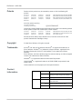
1
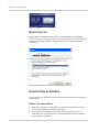
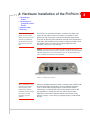
USAT
USATCORP.COM
Contact USATCORP.COM for more
information or quantity pricing
1-888-550-8728
PinPoint X for Verizon
User Guide
20070914
Rev 2.0
PinPoint X for Verizon
User Guide
20070914
Rev 2.0
Preface
Important
Notice
Due to the nature of wireless communications, transmission and reception of data
can never be guaranteed. Data may be delayed, corrupted (i.e., have errors) or be
totally lost. Although significant delays or losses of data are rare when wireless
devices such as the Sierra Wireless AirLink PinPoint X are used in a normal
manner with a well-constructed network, the Sierra Wireless AirLink PinPoint X
should not be used in situations where failure to transmit or receive data could
result in damage of any kind to the user or any other party, including but not
limited to personal injury, death, or loss of property. Sierra Wireless accepts no
responsibility for damages of any kind resulting from delays or errors in data
transmitted or received using the Sierra Wireless AirLink PinPoint X, or for failure
of the Sierra Wireless AirLink PinPoint X to transmit or receive such data.
Safety and
Hazards
Do not operate the Sierra Wireless AirLink PinPoint X in areas where blasting is in
progress, where explosive atmospheres may be present, near medical
equipment, near life support equipment, or any equipment which may be
susceptible to any form of radio interference. In such areas, the Sierra Wireless
AirLink PinPoint X MUST BE POWERED OFF. The Sierra Wireless AirLink
PinPoint X can transmit signals that could interfere with this equipment.
Do not operate the Sierra Wireless AirLink PinPoint X in any aircraft, whether the
aircraft is on the ground or in flight. In aircraft, the Sierra Wireless AirLink PinPoint
X MUST BE POWERED OFF. When operating, the Sierra Wireless AirLink
PinPoint X can transmit signals that could interfere with various onboard systems.
Note: Some airlines may permit the use of cellular phones while the aircraft is on the
ground and the door is open. Sierra Wireless AirLink PinPoint X may be used at this time.
The driver or operator of any vehicle should not operate the Sierra Wireless
AirLink PinPoint X while in control of a vehicle. Doing so will detract from the
driver or operator's control and operation of that vehicle. In some states and
provinces, operating such communications devices while in control of a vehicle is
an offence.
Limitation of
Liability
The information in this manual is subject to change without notice and does not
represent a commitment on the part of Sierra Wireless. SIERRA WIRELESS AND
ITS AFFILIATES SPECIFICALLY DISCLAIM LIABILITY FOR ANY AND ALL
DIRECT, INDIRECT, SPECIAL, GENERAL, INCIDENTAL, CONSEQUENTIAL,
PUNITIVE OR EXEMPLARY DAMAGES INCLUDING, BUT NOT LIMITED TO,
LOSS OF PROFITS OR REVENUE OR ANTICIPATED PROFITS OR REVENUE
ARISING OUT OF THE USE OR INABILITY TO USE ANY SIERRA WIRELESS
PRODUCT, EVEN IF SIERRA WIRELESS AND/OR ITS AFFILIATES HAS BEEN
ADVISED OF THE POSSIBILITY OF SUCH DAMAGES OR THEY ARE
FORESEEABLE OR FOR CLAIMS BY ANY THIRD PARTY.
Notwithstanding the foregoing, in no event shall Sierra Wireless and/or its
affiliates aggregate liability arising under or in connection with the Sierra Wireless
product, regardless of the number of events, occurrences, or claims giving rise to
liability, be in excess of the price paid by the purchaser for the Sierra Wireless
product.
Rev 2.0 Mar.10
i
PinPoint X 1x/EV-DO
Patents
Portions of this product may be covered by some or all of the following US
patents:
5,515,013
6,191,741
6,653,979
6,968,171
D459,303
5,629,960
6,199,168
6,697,030
6,985,757
5,845,216
6,339,405
6,785,830
7,023,878
5,847,553
6,359,591
6,845,249
7,053,843
5,878,2345,890,0575,929,8156,169,884
6,400,3366,516,2046,561,8516,643,501
6,847,8306,876,6976,879,5856,886,049
7,106,5697,145,2677,200,512D442,170
and other patents pending.
This product includes
technology licensed from:
QUALCOMM® 3G
Licensed by QUALCOMM Incorporated under one or more of the following United
States patents and/or their counterparts in other nations:
4,901,307
5,414,796
5,568,483
5,056,109
5,416,797
5,600,754
5,101,501
5,490,165
5,657,420
5,109,390
5,504,773
5,659,569
5,228,0545,267,2615,267,2625,337,338
5,506,8655,511,0735,535,2395,544,196
5,710,7845,778,338
Manufactured or sold by Sierra Wireless or its licensees under one or more
patents licensed from InterDigital Group.
Copyright
© 2010 Sierra Wireless. All rights reserved.
Trademarks
AirCard® and “Heart of the Wireless Machine®” are registered trademarks of
Sierra Wireless. Watcher® is a trademark of Sierra Wireless, registered in the
European Community. AirLink™ and AceWare™ are trademarks of Sierra
Wireless.
Sierra Wireless, the Sierra Wireless logo, the red wave design, and the red-tipped
antenna are trademarks of Sierra Wireless.
Windows® is a registered trademark of Microsoft Corporation.
QUALCOMM® is a registered trademark of QUALCOMM Incorporated. Used
under license.
Other trademarks are the property of the respective owners.
Contact
Information
Support Desk:
Phone: 1-877-231-1144
Hours: 5:00 AM to 5:00 PM Pacific Time,
Monday to Friday, except US Holidays
E-mail: [email protected]
Sales Desk:
Phone: 1-510-624-4200
1-604-232-1488
Hours: 8:00 AM to 5:00 PM Pacific Time
E-mail: [email protected]
ii
20070914
Preface
Post: Sierra Wireless America
39677 Eureka Drive
Newark, CA
USA
94560
Sierra Wireless
13811 Wireless Way
Richmond, BC
Canada
V6V 3A4
Fax: 1-510-624-4299
1-604-231-1109
Web: www.sierrawireless.com
Consult our website for up-to-date product descriptions, documentation,
application notes, firmware upgrades, troubleshooting tips, and press releases:
www.sierrawireless.com
Revision
History
Revision
number
Release date
Changes
1.x
Q2: 2009
Guide updated with ALEOS Release 4.0 content.
2.x
Q1: 2010
User Guide rebranded to current corporate standards.
Rev 2.0 Mar.10
iii
PinPoint X 1x/EV-DO
iv
20070914
Contents
Introduction to the PinPoint X . . . . . . . . . . . . . . . . . . . . . . . . . . . . . . . . . . . . . .1
ACEmanager . . . . . . . . . . . . . . . . . . . . . . . . . . . . . . . . . . . . . . . . . . . . . . .2
Simplified Deployment. . . . . . . . . . . . . . . . . . . . . . . . . . . . . . . . . . . . . 3
Monitor and Control . . . . . . . . . . . . . . . . . . . . . . . . . . . . . . . . . . . . . . . 3
ACEview . . . . . . . . . . . . . . . . . . . . . . . . . . . . . . . . . . . . . . . . . . . . . . . . . .3
Modem Doctor . . . . . . . . . . . . . . . . . . . . . . . . . . . . . . . . . . . . . . . . . . . . . .4
Connecting to Verizon . . . . . . . . . . . . . . . . . . . . . . . . . . . . . . . . . . . . . . . . . . 4
Steps of a connection: . . . . . . . . . . . . . . . . . . . . . . . . . . . . . . . . . . . . . 4
Dynamic vs. Static IP Addresses . . . . . . . . . . . . . . . . . . . . . . . . . . . . . . . .5
EV-DO . . . . . . . . . . . . . . . . . . . . . . . . . . . . . . . . . . . . . . . . . . . . . . . . . . . . . 6
Security . . . . . . . . . . . . . . . . . . . . . . . . . . . . . . . . . . . . . . . . . . . . . . . . 6
Connection methods . . . . . . . . . . . . . . . . . . . . . . . . . . . . . . . . . . . . . . . . . . . 6
USB . . . . . . . . . . . . . . . . . . . . . . . . . . . . . . . . . . . . . . . . . . . . . . . . . . . . . .6
Virtual serial port . . . . . . . . . . . . . . . . . . . . . . . . . . . . . . . . . . . . . . . . . . . .7
Networking . . . . . . . . . . . . . . . . . . . . . . . . . . . . . . . . . . . . . . . . . . . . . . . . . . . 7
IPSec . . . . . . . . . . . . . . . . . . . . . . . . . . . . . . . . . . . . . . . . . . . . . . . . . . . . .7
GRE . . . . . . . . . . . . . . . . . . . . . . . . . . . . . . . . . . . . . . . . . . . . . . . . . . . . . .8
Applications . . . . . . . . . . . . . . . . . . . . . . . . . . . . . . . . . . . . . . . . . . . . . . . . . . 8
Events Reporting . . . . . . . . . . . . . . . . . . . . . . . . . . . . . . . . . . . . . . . . . . . .8
Software . . . . . . . . . . . . . . . . . . . . . . . . . . . . . . . . . . . . . . . . . . . . . . . . . . . . . 8
Documentation . . . . . . . . . . . . . . . . . . . . . . . . . . . . . . . . . . . . . . . . . . . . . . . . 9
Tools and Reference Documents . . . . . . . . . . . . . . . . . . . . . . . . . . . . . . .9
Specifications . . . . . . . . . . . . . . . . . . . . . . . . . . . . . . . . . . . . . . . . . . . . . . . . . . 11
Features and Benefits . . . . . . . . . . . . . . . . . . . . . . . . . . . . . . . . . . . . 11
Technology . . . . . . . . . . . . . . . . . . . . . . . . . . . . . . . . . . . . . . . . . . . . 11
Bands . . . . . . . . . . . . . . . . . . . . . . . . . . . . . . . . . . . . . . . . . . . . . . . . 11
Environmental . . . . . . . . . . . . . . . . . . . . . . . . . . . . . . . . . . . . . . . . . . 11
Power Consumption: (@12V DC) . . . . . . . . . . . . . . . . . . . . . . . . . . . 11
Standards/Approvals . . . . . . . . . . . . . . . . . . . . . . . . . . . . . . . . . . . . . 12
Host Interfaces . . . . . . . . . . . . . . . . . . . . . . . . . . . . . . . . . . . . . . . . . 12
Dimensions . . . . . . . . . . . . . . . . . . . . . . . . . . . . . . . . . . . . . . . . . . . . 12
Application Interfaces . . . . . . . . . . . . . . . . . . . . . . . . . . . . . . . . . . . . 12
LED Indicators . . . . . . . . . . . . . . . . . . . . . . . . . . . . . . . . . . . . . . . . . . 12
Rev 2.0 Mar.10
v
PinPoint X 1x/EV-DO
Interface Port Pin-Outs . . . . . . . . . . . . . . . . . . . . . . . . . . . . . . . . . . . . . . . . 13
Serial Port . . . . . . . . . . . . . . . . . . . . . . . . . . . . . . . . . . . . . . . . . . . . . 13
Power Connector . . . . . . . . . . . . . . . . . . . . . . . . . . . . . . . . . . . . . . . . . . . . . 14
Activating your PinPoint X on Verizon . . . . . . . . . . . . . . . . . . . . . . . . . . . . . . 15
Automatic Activation . . . . . . . . . . . . . . . . . . . . . . . . . . . . . . . . . . . . . . . . . . 15
Setup Wizard . . . . . . . . . . . . . . . . . . . . . . . . . . . . . . . . . . . . . . . . . . . . . . . . 16
Manual . . . . . . . . . . . . . . . . . . . . . . . . . . . . . . . . . . . . . . . . . . . . . . . 19
Activating Using AT Commands . . . . . . . . . . . . . . . . . . . . . . . . . . . . . . . . . 26
Hardware Installation of the PinPoint X . . . . . . . . . . . . . . . . . . . . . . . . . . . . . 27
Connecting to a Computer or other Device . . . . . . . . . . . . . . . . . . . . . . . . 29
Indicator Lights . . . . . . . . . . . . . . . . . . . . . . . . . . . . . . . . . . . . . . . . . . . . . . 30
Light Patterns . . . . . . . . . . . . . . . . . . . . . . . . . . . . . . . . . . . . . . . . . . 31
Mounting . . . . . . . . . . . . . . . . . . . . . . . . . . . . . . . . . . . . . . . . . . . . . . . . . . . 33
Configuring the PinPoint X . . . . . . . . . . . . . . . . . . . . . . . . . . . . . . . . . . . . . . . 35
ACEmanager . . . . . . . . . . . . . . . . . . . . . . . . . . . . . . . . . . . . . . . . . . . . . . . . 35
Using a Terminal Application with AT Commands. . . . . . . . . . . . . . . . . . . . 35
AT Command. . . . . . . . . . . . . . . . . . . . . . . . . . . . . . . . . . . . . . . . . . . . . . . . 38
Inputs, Relay Outputs, and Power Status . . . . . . . . . . . . . . . . . . . . . . . . . . . 41
Capturing External Events . . . . . . . . . . . . . . . . . . . . . . . . . . . . . . . . . . . . . . 41
Analog Inputs . . . . . . . . . . . . . . . . . . . . . . . . . . . . . . . . . . . . . . . . . . 41
Digital Inputs . . . . . . . . . . . . . . . . . . . . . . . . . . . . . . . . . . . . . . . . . . . 42
Relay Outputs . . . . . . . . . . . . . . . . . . . . . . . . . . . . . . . . . . . . . . . . . . 42
Connecting devices to the I/O Port . . . . . . . . . . . . . . . . . . . . . . . . . . . . . 43
Analog Inputs . . . . . . . . . . . . . . . . . . . . . . . . . . . . . . . . . . . . . . . . . . 45
Digital Inputs . . . . . . . . . . . . . . . . . . . . . . . . . . . . . . . . . . . . . . . . . . . 45
Relay Outputs . . . . . . . . . . . . . . . . . . . . . . . . . . . . . . . . . . . . . . . . . . 45
Monitoring and Setting the I/O . . . . . . . . . . . . . . . . . . . . . . . . . . . . . . . . . 45
Getting Immediate Reports Using RAP . . . . . . . . . . . . . . . . . . . . . . 45
vi
20070914
Contents
Power Modes and Information . . . . . . . . . . . . . . . . . . . . . . . . . . . . . . . . . . . 45
Wiring the PinPoint X for . . . . . . . . . . . . . . . . . . . . . . . . . . . . . . . . . . . . . 46
Power Effect on Modem State . . . . . . . . . . . . . . . . . . . . . . . . . . . . . . . . . 46
Monitoring Power-In Voltage . . . . . . . . . . . . . . . . . . . . . . . . . . . . . . . . . 46
Regulatory Information . . . . . . . . . . . . . . . . . . . . . . . . . . . . . . . . . . . . . . . . . . 47
Federal Communications Commission Notice (FCC United States) . . . . 47
Industry Canada . . . . . . . . . . . . . . . . . . . . . . . . . . . . . . . . . . . . . . . . . . . . 47
Antenna Considerations . . . . . . . . . . . . . . . . . . . . . . . . . . . . . . . . . . 48
RF Exposure . . . . . . . . . . . . . . . . . . . . . . . . . . . . . . . . . . . . . . . . . . . . . . 48
EU . . . . . . . . . . . . . . . . . . . . . . . . . . . . . . . . . . . . . . . . . . . . . . . . . . . . . . 48
WEEE Notice. . . . . . . . . . . . . . . . . . . . . . . . . . . . . . . . . . . . . . . . . . . 49
Rev 2.0 Mar.10
vii
PinPoint X 1x/EV-DO
viii
20070914
1
1: Introduction to the PinPoint X
• Connecting to
Verizon
• EV-DO
• Connection
methods
• Networking
• Applications
• Software
• Documentation
The PinPoint X is a compact, intelligent and fully-featured mobile
communications platform with multiple peripheral connections
including serial, Ethernet and USB. Expanded I/O functionality in a
separate connector includes four digital inputs, four analog inputs and
two relay outputs unleashing extensive remote instrumentation
possibilities.
Its high-precision 50-channel GPS receiver coupled with the rich
embedded intelligence provided by ALEOS™ technology make
PinPoint X the perfect choice for a broad set of mobile enterprise,
public safety, fleet management and AVL solutions.
Figure 1-1: Sierra Wireless AirLink PinPoint X
ALEOS, the embedded core technology of the Sierra Wireless
AirLink products simplifies installation, operation and maintenance of
any solution, and provides an always-on, always-aware intelligent
connection for mission-critical applications. ALEOS enables:
Rev 2.0 Mar.10
•
Persistent Network Connectivity
•
Over-The-Air (OTA) Upgrades
•
Wireless Optimized TCP/IP
•
Real-Time Notification
•
Real-Time GPS Reporting
•
GPS Store and Forward
•
Packet Level Diagnostics
1
PinPoint X 1x/EV-DO
•
Device Management & Control
•
Protocol Spoofing
Figure 1-2: Powered by ALEOS
A wireless solution is not complete until you have software tools to manage the
devices monitoring your valuable equipment. Using the AirLink Control
Environment (ACE), ACEWare is the device management and monitoring
application suite for Sierra Wireless AirLink devices powered by ALEOS.
Figure 1-3: ACEware Logo
The ACEware suite encompasses an application internal to the firmware (
ACEmanager), Windows-based applications (ACEview and Modem Doctor), and
a web-hosted application (ACEnet). You can download the applications and their
user guides from the Sierra Wireless AirLink Solutions web site: http://
www.sierrawireless.com/support. Contact your dealer or Sierra Wireless
representative for any further information.
Note: ACEview requires the Microsoft .NET Framework v. 2.0 and Microsoft Windows 98,
Windows 2000, Windows XP, or later. You can obtain the Microsoft .NET Framework from
Microsoft at: http://www.microsoft.com/.
ACEmanager
ACEmanager, the AceWare remote configuration and monitoring tool, simplifies
deployment and provides extensive monitoring, control and management
capabilities. ACEmanager gives you the power to monitor and control your Sierra
Wireless AirLink communications platforms in real-time.
2
20070914
Introduction to the PinPoint X
Figure 1-4: ACEmanager
Simplified Deployment
ACEmanager provides the ability to remotely set up and configure your Sierra
Wireless AirLink products. Remote device setup and configuration reduces the
deployment timeline of your wireless solution and provides a quicker path to ROI.
Templates allow you to easily configure devices in your fleet with identical
settings, ensuring a simple, accurate deployment.
Monitor and Control
ACEmanager allows an administrator to remotely monitor a modem’s status,
health and configuration settings. The user interface displays signal strength, cell
site information, byte counters and error conditions, enabling you to pinpoint any
issues and troubleshoot immediately.
ACEmanager enables remote configuration and parameter settings to be
changed or reset instantly over the air, change a device’s port configuration, IP
address settings, GPS settings, and much more. After configuring one modem,
use the template feature to copy that device configuration to other devices.
Tip: Configuration steps and examples in this guide use ACEmanager.
ACEview
ACEview is an efficient status and connection monitoring application with a lowprofile, easy to read interface. In ACEview, you can also update PRL.
Rev 2.0 Mar.10
3
PinPoint X 1x/EV-DO
Figure 1-5: ACEview
Modem Doctor
Modem Doctor and Modem Doctor USB is a troubleshooting and diagnostics
utility. This utility will allow you to get a log file of the PinPoint X activity which you
can then send to Sierra Wireless support or erase the current configuration
completely.
Figure 1-6: Modem Doctor
Connecting to Verizon
The PinPoint X uses Verizon as an ISP (Internet Service Provider) to connect you
to the Internet.
Steps of a connection:
1. When your PinPoint X is powered on, it automatically searches for cellular
service using CDMA-based cellular technology.
2. Your PinPoint X establishes a PPP (Point to Point Protocol or “dial” up
connection) link to Verizon network, also called registering on the network,
and receives an IP address.
4
20070914
Introduction to the PinPoint X
3. When your PinPoint X has received its IP address from Verizon, a connection
to the Internet or the cellular network is also available for computers or other
devices connected directly to the PinPoint X.
The PinPoint X will perform routing for all internet traffic to and from the
computers or other end devicse.
With the PinPoint X in Ethernet Public mode, only one device connected to the
Ethernet port will receive the public IP address which is the one provided by the
cellular network. In Ethernet Private mode, with a hub or switch connected to the
Ethernet port, the PinPoint X will provide NAT for a range of computers or other
devices connected to the switch or hub and Internet access to all of them.
Dynamic vs. Static IP Addresses
There are two types of addresses on networks: dynamic and static.
•
Dynamic addresses are assigned on a “need to have” basis. Your PinPoint X
might not always receive the same address each time it connects with
Verizon.
•
Static addresses are permanently assigned to a particular account and will
always be used whenever your PinPoint X connects to the Internet. The IP
address will not be given to anyone else.
Most ISPs (cellular included) use dynamic IP addresses rather than static IP
addresses since it allows them to reuse a smaller number of IP addresses for a
large number of customers. A dynamic IP address is suitable for many common
Internet uses, such as web browsing, looking up data on another computer
system, or other client functions (such as data only being sent out or only being
received after an initial request).
Tip: If your account with Verizon includes a dynamic IP address and you need a static IP,
please consult your Verizon Representative for more information about changing your
account for static IP support.
If you need to contact your PinPoint X, a device connected to the PinPoint X, or a
host system using the PinPoint X from the Internet, you need to have a known IP
(such as one which is static) or domain name (an IP address which is converted
by a DNS server into a word based name). If you have a dynamic IP address for
your modem, you can use a Dynamic DNS service (such as IP Manager) to
translate your IP address into to a domain name.
Rev 2.0 Mar.10
5
PinPoint X 1x/EV-DO
Caution: If you want to connect remotely to your PinPoint X using TCP/IP, the IP address
given to your modem by Verizon cannot be a private or internal IP address (such as a
special private network) unless you are on the same network or inside that network’s
firewall (such as with frame relay).
EV-DO
CDMA (Code Division Multiple Access) is the underlying digital radio network
technology used by many cellular providers across the globe and is prevalent in
North America. To provide backward compatibility and seamless connections in
a wider range of locations, Sierra Wireless EV-DO products your PinPoint X will
fall back to 1x when EV-DO is not available.
Sierra Wireless is certified with Verizon, a prominent North American 1x and EVDO carrier.
EV-DO revision A is an enhancement on the original revision 0 adding expanded
upload capabilities and a more robust connection overall. In addition to increasing
the downlink speed, revision A also increases the uplink speed. In addition, it is
backwards compatible and automatically connects with existing and broadly
deployed EV-DO Rev. 0 and 1x networks ensuring reliable and pervasive
connectivity.
Security
1x data transmissions are highly secure. Originally developed based upon the
“spread spectrum” pioneered by the US Department of Defense, security in
CDMA technologies is obtained by spreading the digital information contained in
a particular signal of interest over multiple coded paths, over a much greater
bandwidth than the original signal.
Connection methods
You can connect the PinPoint X to a USB or a Ethernet (RJ45) on a computer.
When connected to a USB or Ethernet port, the PinPoint X behaves like a
network card.
USB
The PinPoint X is equipped with a USB port which increases the methods by
which you can send and receive data. The USB port can be set to work as either
a virtual Ethernet port or a virtual serial port. A driver installation is required to
use the USB port in either mode.
It is recommended that you use a USB 2.0 cable with your PinPoint X and
connect directly to your computer for best throughput.
6
20070914
Introduction to the PinPoint X
Virtual serial port
The PinPoint X supports one virtual serial port over USB. This VSP can be used,
for example, to send AT commands, or to run many serial based applications
such as HyperTerminal®.
Networking
IPSec
The IP protocol that drives the Internet is inherently insecure. Internet Protocol
Security (IPSec), which is a standards-based protocol, secures communications
of IP packets over public networks.
IPSec is a common network layer security control and is used to create a virtual
private network (VPN).
The advantages of the IPSec feature includes:
•
Data Protection: Data Content Confidentiality allows users to protect their
data from any unauthorized view, because the data is encrypted (encryption
algorithms are used).
•
Access Control: Access Control implies a security service that prevents
unauthorized use of a Security Gateway, a network behind a gateway or
bandwidth on that network.
•
Data Origin Authentication: Data Origin Authentication verifies the actual
sender, thus eliminating the possibility of forging the actual sender’s identification by a third-party.
•
Data Integrity: Data Integrity Authentication allows both ends of the communication channel to confirm that the original data sent has been received as
transmitted, without being tampered with in transit. This is achieved by using
authentication algorithms and their outputs.
The IPSec architecture model includes the Sierra Wireless AirLink gateway as a
remote gateway at one end communicating, through a VPN tunnel, with a VPN
gateway at the other end. The remote gateway is connected to a Remote network
and the VPN is connected to the Local network. The communication of data is
secure through the IPSec protocols.
Rev 2.0 Mar.10
7
PinPoint X 1x/EV-DO
Figure 1-7: IPSec Architecture
GRE
GRE (Generic Routing Encapsulation) tunnel is used to carry non-IP packets
through an IP Network. Non -IP packets, that are send over the GRE tunnel, need
to be first encapsulated. Hence, ALEOS is used to configure and encapsulate
non-IP packets and transmit over IP through the GRE tunnel.
Applications
Events Reporting
Events Reporting is Sierra Wireless AirLink’s modem’s new software feature
provided via ACEmanager, that allows the users to generate reports from the
events that take place. Event Reporting Protocol is an intuitive embedded
protocol, which automatically formats the messages based on an event trigger.
The messages generated are then reported to the remote server.
Software
The PinPoint X modem comes with the following software:
•
AceView, the software for the PinPoint X which allows you to monitor your
connections.
•
The driver that forms the interface between the PinPoint X and your Windows
operating system when using USB virtual Ethernet or USB virtual serial.
•
The firmware that is stored in non-volatile memory and includes
ACEmanager.
The PinPoint X has an embedded radio module, also made by Sierra Wireless, Inc. There are two firmware programs on the device—one stored on the
controller board of the PinPoint X and one on the radio module.
The firmware was loaded into the radio module and controller board when the
PinPoint X was assembled. As new versions of the software and firmware are
released, they are posted at www.sierrawireless.com.
8
20070914
Introduction to the PinPoint X
Documentation
This PinPoint X User Guide describes how to:
•
Install the PinPoint X hardware.
•
Connect the radio antennas.
•
Connect a notebook computer and other input/output
(I/O) devices.
•
Interpret the LEDs on the PinPoint X and the indicators in the AceView
software.
This User Guide is provided as a PDF (Portable Document Format) file on the
installation CD or from the Sierra Wireless support website.
Tools and Reference Documents
User Guide
Description
ALEOS User Guide
This document discusses software configuration in ACEmanager and explains all the
ALEOS features.
ACEview User Guide
This document explains the use of this utility tools which is used to view and monitor the
connection state of a Sierra Wireless AirLink device.
ACEnet User Guide
This document explains the use of ACEnet services for remote management of Sierra
Wireless AirLink device.
Rev 2.0 Mar.10
9
PinPoint X 1x/EV-DO
10
20070914
2
2: Specifications
• Interface Port PinOuts
• Power Connector
Features and Benefits
•
Embedded Intelligence
•
Low Power Consumption
•
High-Speed Processor
•
High-Speed 2-way Data
•
Multiple Interfaces, I/O Port
•
High-Sensitivity GPS Receiver
•
Persistent Network Connectivity
•
Remote Management and Configuration
•
Extensive Vehicle Telemetry
•
Integrated with 3rd Party Tracking Applications
•
Rugged for Extreme Environments
Technology
•
CDMA EV-DO Revision A
With Fallback to:
· CDMA 1x EV-DO (Revision 0)
· CDMA 1xRTT
· CDMA IS-95
Bands
•
800 Mhz Cellular
•
1900 Mhz PCS
Environmental
•
Operating Temperature:
· -30° to 70° Celsius
•
° Storage Temperature:
· -40° to 85° Celsius
Power Consumption: (@12V DC)
Rev 2.0 Mar.10
•
Transmit/Receive (Typical/Max) 316/340 mA
•
Idle 166 mA
•
Low Power Mode 54 mA
•
Input Voltage 9 - 28V DC
11
PinPoint X 1x/EV-DO
Standards/Approvals
•
Carrier specific approvals
•
FCC
•
Industry Canada
Host Interfaces
•
Ethernet: 10/100 Mbps RJ-45
•
USB Type B
•
RS-232: DB-9 DCE (300-230400 baud)
•
I/O: 4 Digital, 4 Analog, 2 Relay
•
Antenna Connection:
· Primary Cellular - 50 Ohm TNC
· Receive Diversity - 50 Ohm SMA
· GPS - 50 Ohm SMA
Warning: The antenna should be installed no closer than 20 cm from the human body. It
is one of the RSS-102 requirements for devices not requiring SAR.
Dimensions
•
162mm x 40mm x 109mm
•
612 grams
Application Interfaces
•
TCP/IP, UDP/IP, DHCP, HTTP, SNMP, SMTP, SMS, MSCI, NMEA, TAIP, GPS,
and more
LED Indicators
12
•
Network
•
Signal
•
Activity
•
GPS
•
Power
20070914
Specifications
Interface Port Pin-Outs
Serial Port
Unused
CTS (Clear to Send) < RTS (Request to Send) - >
DSR (Data to Send) < -
9
5
8
7
6
4
3
2
1
< - > GND (Ground)
< - DTR Data Terminal Ready)
< - Rx (Receive)
- > Tx (Transmit)
- > DCD (Data Carrier Detect)
Figure 2-1: Serial Port Diagram: Female DB-9 DCE (not to scale)
Note: The Pin-Out diagram shows external view looking at PinPoint X connector in front
face-plate of device. Pin 1 is lower right.
22
21
20 19
18
17
16
15
14
13
12
Relay 1 Rsv
NC AIN1 GND AIN3
DIN1 GND DIN3GND
NO1Com1
Relay
2
DIN2GND DIN4 GND
Rsv NC AIN2 GND AIN4
NO2Com2
11
10
9
8
7
6
5
4
3
2
1
Figure 2-2: PinPoint X I/O Port Diagram (not to scale)
Rev 2.0 Mar.10
1. Analog Input 4
12. Analog Input 3
2. Analog Ground
13. Analog Ground
3. Analog Input 2
14. Analog Input 1
4. No Connect
15. No Connect
5. Reserved for future use
16. Reserved for future use
6. Com2 (for use with #7)
17. Com1 (for use with #18)
7. Normal Open Relay
18. Normal Open Relay
8. GND
19. GND
9. Digital Input 4
20. Digital Input 3
10. Ground
21. Ground
11. Digital Input 2
22. Digital Input 1
13
PinPoint X 1x/EV-DO
Power Connector
Not Used 4
3
Ignition Sense (white)
Ground (black) 2
1
Power (red)
Figure 2-3: Power Connector (not to scale)
14
20070914
3: Activating your PinPoint X on Verizon 3
• Automatic
Activation
• Setup Wizard
• Activating Using AT
Commands
This chapter provides step-by-step directions for activating your
PinPoint X on Verizon’s network.
H
Automatic Activation
One of the special features of your PinPoint X for Verizon is the
ability to activate itself automatically. When you first power on
the PinPoint X, it will check to see if it has been activated with
account data. If it finds that it has not yet been activated, the
PinPoint X will attempt to retrieve the account data from the
Verizon network using Over-the-Air Service Provisioning
(OTASP).
Caution: You need to have an account with Verizon before you
attempt automatic activation. If you have not ordered an account
from Verizon for your PinPoint X, it will not succeed at activating.
a. Attach the antenna to your PinPoint X.
b. Plug the PinPoint X into power.
c. While the LED lights cycle from the outside to the
inside, the PinPoint X is attempting to download its
account information. The download process may take
about a minute or two.
Caution: Do not move your PinPoint X while it is being programmed.
d. When the lights illuminate, your PinPoint X has
successfully completed OTASP and is registered on
the Verizon network.
e.
If you need to update the ALEOS firmware,
change the account information, install the Dial-Up
Networking driver, or want to test the account settings
of your PinPoint X, follow the directions below to use
the Setup Wizard. Otherwise, skip the Wizard steps
and go to the Hardware Installation section.
Note: If you were able to successfully activate your PinPoint X with
Automatic Activation, you do not need to use the Setup Wizard to activate
your modem.
Rev 2.0 Mar.10
15
PinPoint X 1x/EV-DO
Setup Wizard
You can find the Setup Wizard installation on the CD which came with your
PinPoint X or on the Sierra Wireless website: http://www.sierrawireless.com/
support/AirLink/default.aspx.Use only the Setup Wizard for Verizon for best
results.
Note: The Setup Wizard
requires the Microsoft
.NET framework v. 1.1 and
Microsoft Windows 98,
Windows 2000, Windows
XP, or later. You can obtain
.NET from Microsoft: http://
www.microsoft.com.
1. Wizard: Starting the Setup Wizard
a. Connect the PinPoint X to your computer using an Ethernet cable or a
serial cable USB cable.
b. Connect the power adapter and antenna to your PinPoint X.
c. Install the Setup Wizard by running VerizonSetupWizard.exe and follow
the prompts.
d. Run the Setup Wizard from the Windows Start menu.
Start>All Programs>AirLink Communications>Setup Wizard>Setup Wizard
Figure 3-1: Setup Wizard
e. Click Next to start the Wizard process.
If you connected your PinPoint X to the port on your computer, select Connected
to an Ethernet/USB Port and use the drop down menu to select the Ethernet
adapter or USB/net connectionon your computer to which the modem is
connected (most computers only have one adapter which will be selected for
you). The default password for the modem is entered for you. Click Next.
Note: If you want to use USB with the Setup Wizard you will need to first install the driver,
refer to Installing the USB driver section in this Chapter.
16
20070914
Activating your PinPoint X on Verizon
Figure 3-2: Setup Wizard : Ethernet Connection/USB Connection
Figure 3-3: Ethernet Port
Tip: If the Setup Wizard is unable to detect the PinPoint X, check the green link LED on
the Ethernet port of the modem to see if it is lit to indicate an Ethernet connection with your
computer. If you do not see this light or if your computer shows a “Network Cable
Unplugged” message or icon, try a different Ethernet cable.
OR
If you connected your PinPoint X to the serial port on your computer, select
Connected to a Serial Port, check Auto Detect Port Settings or select the port
from the drop down menu. Click Next.
Figure 3-4: Setup Wizard : Serial Connection
Note: You cannot activate with serial and would need USB/net to use set up wizard.
Rev 2.0 Mar.10
17
PinPoint X 1x/EV-DO
After the Setup Wizard connects to your PinPoint X, the details for your specific
model will be displayed. If the incorrect model is displayed, press the Reset
Button on your PinPoint X so the Wizard can attempt to connect again. Click
Next.
After the Wizard detects your PinPoint X, you will be offered a menu of Setup
tasks. Choose the tasks you need from those displayed.
Figure 3-5: Setup Wizard : Task Menu
•
•
Update ALEOS Firmware: Check the Sierra Wireless server for the latest
ALEOS firmware.
Activate Modem: Configure your PinPoint X to connect on
the Verizon network.
•
Test Modem Setup: Verify your PinPoint X is properly configured and
connecting on the Verizon network.
•
Setup a DUN Connection: Create a Dial-Up Networking entry for local
connection. This part of the setup is only needed if you will be using your
PinPoint X to connect directly from a computer to the Internet or other
network.
Click Next when you have selected your desired options.
Note: Based on your selections, you may not need to do all of the following Wizard steps.
18
20070914
Activating your PinPoint X on Verizon
Note: Follow this step, only if Update Aleos option has been selected in the task menu
checkbox
On occasion, Sierra Wireless releases updates to the firmware for your modem.
These updates can include new features as well as bug fixes. To make sure your
modem is at optimal performance, it is recommended to Check for Updates and
Update Now if an update is found.
Note: While checking for ALEOS Firmware updates, the Setup Wizard uses the Internet
connection on your computer to connect to the Sierra Wireless server. Your PinPoint X is
not connected to the wireless network for this process. If you are using Ethernet to activate
your Product Name and need to remove the Ethernet cable from your modem to connect
to your usual Internet connection to Check for Updates, be sure to reconnect the PinPoint
X before you select Update Now.
Figure 3-6: ALEOS Update
Tip: You can download current ALEOS firmware from the Sierra Wireless web site and
install it separately.
Click Next when you are finished updating or if you choose not to update.
The steps and data required to activate your PinPoint X on the Verizon network
varies depending on the model. The Wizard is designed to support older models
as well as those currently shipping
Manual
To configure or provision your modem to work on the Verizon network, you will
need device activation information provided by Verizon.
Fill in the requested information and click Next on each screen.
Rev 2.0 Mar.10
19
PinPoint X 1x/EV-DO
Figure 3-7: Setup Wizard : MSL
•
MDN - The phone number of your cellular account.
•
MIN or MSID - The identification number for your cellular account.
Figure 3-8: Setup Wizard MDN and MIN/MSID
•
Static IP - If you have a cellular account with a static IP
address, check this box if it is displayed.
Caution: If you do not have a static IP account and check the Static
IP box, you may not be able to activate your PinPoint X or register on
the Verizon network.
The Wizard will check the signal strength of your PinPoint X (RSSI). Click Next to
begin the activation process.
Note: The process may take a few minutes. Progress information will display across the
bottom.
20
20070914
Activating your PinPoint X on Verizon
Figure 3-9: Setup Wizard : Signal Test
Note: If you did not need to enter any data, no settings will be displayed.
Tip: If you have low signal, you may encounter difficulties activating your modem. Try a
different location or a different antenna to increase your signal if it is -90 or lower (yellow to
red bar).
Figure 3-10: Setup Wizard: OTASP screen
Tip: The PinPoint X will get all of its account data from the next work while doing an over
the air activation (OTASP).
Your connection of your PinPoint X to the Internet is tested using the Verizon
cellular network.
Rev 2.0 Mar.10
21
PinPoint X 1x/EV-DO
Figure 3-11: Setup Wizard: Connection Test
Green checks in the boxes indicate the tests were successful and your PinPoint X
is functioning properly. At this point your modem is configured and activated to
work on the Verizon network.
Note: These tests, depending on the strength of your signal, may take a few minutes.
Initially, while the tests are being performed, there may be red Xs in the boxes. The Status
line will give an indication of the progress of the connection process.
If Test Modem Settings shows the status of your modem is “Data Connection
Failed - Waiting for Retry”, “No Service”, “No Carrier”, “Network Negotiation
Failed”, “Network Authentication Failed”, “Modem Not Registered”, or the Reg Net
light on the modem is not lit, double-check your device activation information and
return to the Activate Modem step to reconfigure your PinPoint X.
Private Networking Data Link is a special account configuration that provides a
more secure connection for your PinPoint X and often provides a static IP with
authentication on an exclusive server. Consult your Verizon representative for
details about Private Networking Data Link if it’s something you need for your
account.
Before you start the configuration for Private Networking, Data Link, the
connection to the network may be checked.
Caution: Ensure the PinPoint X has been activated before you proceed with the Private
Networking Data Link steps. Configuring Private Networking Data Link before the PinPoint
X has been activated can prevent successful activation.
•
22
The Primary Home Agent (Primary HA) and Secondary Home Agent
(Secondary HA) are the network servers responsible for IP addressing and
routing. Fill in the information, as applicable.
20070914
Activating your PinPoint X on Verizon
Figure 3-12: Setup Wizard : Primary and Secondardy HA
•
HA Shared Secret Password is used for both Home Agent’s. This may be
filled in for you with a password created for your PinPoint X for the Verizon
network.
•
The AAA/Vision Password is required by the Authentication, Authorization
and Accounting server. This may be filled in for you with default for Verizon.
Figure 3-13: Setup Wizard : Passwords
When the Private Networking Data Link configuration is completed, the
connection to the network will be tested again.
Note: Using DUN, the
speed of the connection is
the limited to the
connection between the
modem and the computer.
This may be less than the
total bandwidth available
with EV-DO HSDPA.
Rev 2.0 Mar.10
Dial-up Networking (DUN) allows a computer or other device to use the serial port
on a PinPoint X to connect to the Internet or private network just like an analog
modem using a standard phone line. The Setup Wizard will install a driver for the
PinPoint X and set up the connection between your computer and the PinPoint X.
You will need to have administrator access on the computer for this section of the
installation.
23
PinPoint X 1x/EV-DO
If you already have other modems installed on your computer, they will be listed
on the Sierra Wireless AirLink Modem Installation screen. If you have other
modems installed on your computer using the same serial port, they may conflict.
As long as you do not intend to use them, you can Remove other modems using
this menu.
Figure 3-14: Setup Wizard : DUN driver
a. Select Install to begin adding the driver for the PinPoint X to your
computer.
Figure 3-15: Setup Wizard : DUN settings
b. The COM port and speed should match the settings of the PinPoint X and
where it will be connected (default settings will be pre-entered).
c. Select Next to begin the driver installation.
d. You will see a confirmation box from Microsoft Windows to specify if you
wish to install this driver on your computer. Select Continue Anyway to
install the driver.
e. When the driver is installed, you will return to the Modem installation
screen. The PinPoint X should now be listed (in addition to any other
modem installed on your computer).
f.
24
Click Next to continue to install the DUN configuration.
20070914
Activating your PinPoint X on Verizon
Figure 3-16: Setup Wizard : DUN connections
If you already have a DUN connection installed for a different modem, it will be
listed on the Dial-up Networking Connection screen.
g. Select Add to create a new connection for the PinPoint X.
Figure 3-17: Setup Wizard : DUN settings
h. From the drop down menu, select Sierra Wireless modem.
i.
The defaults for the phone number, user name and password will already
be entered.
j.
Select Next to begin the install.
Figure 3-18: Setup Wizard : DUN
At the completion of the DUN installation, you will return to the Dial-up Networking
Connection screen. The AirLink modem should now be listed as a connection.
Rev 2.0 Mar.10
25
PinPoint X 1x/EV-DO
Your modem is now ready to be used as a DUN device for any applications on
your computer needing a network connection. If you have DUN installed for more
than one modem, you will need to specify in your application which DUN to use.
Unless it is the only DUN, your PinPoint X may not be the one your computer
sees as a default.
Activating Using AT Commands
An alternate method to configure and activate your PinPoint X is by using AT
commands sent directly to the modem with a terminal application. (Refer to the
troubleshooting section). This method is recommended only in situations where
the Setup Wizard is not available and/or when the configuration for the PinPoint X
is unusual.
Caution: It is not possible to activate the PinPoint X using either ACEmanager or AceNet.
1. Set telnet timeout in to 20 minutes.
2. Save the telnet setting.
3. Enter the user name of your account (NAI). The user name is usually
expressed as an email address with phone number of the account (example,
[email protected]). This information should be provided by your carrier.
You may not need this step.
AT*NETUID=[NAI]
4. Enter the password of your account. This information should be provided by
your carrier. You may not need this step.
AT*NETPW=[password]
5. Verify ALEOS has established communication to the internal hardware.
6. Enter the activation command appropriate for your type of account. The SID
and NID are optional and only required if your account type uses them.
· If you have the same number for the MIN and MDN or MSID:
AT*PROVISION=MSL,MDN[,SID,NID]
· If you have the different numbers for the MIN and MDN or MSID:
AT*PROVISION2=MSL,MDN,MIN/MSID[,SID,NID]
7. Start the IOTA session.
AT!IOTASTART
Status will be output until IOTA completes with ‘IOTA Successful’ or ‘ 1012
ERROR’.
26
20070914
4: Hardware Installation of the PinPoint X 4
• Connecting to
Power
• Connecting to a
Computer or other
Device
• Indicator Lights
• Mounting
Note: During installation,
please be sure that the
cables are secure but do
not bear any additional
weight that could loosen
the connector from the
unit.
Your PinPoint X should be mounted in a position that allows easy
access for the cables so they are not bent, constricted, in close
proximity to high amperage, or exposed to extreme temperatures.
The LEDs on the front panel should be visible for ease of operational
verification. You should ensure that there is adequate airflow around
the modem but that it is kept free from direct exposure to the
elements, such as sun, rain, dust, etc.
Caution: The PinPoint X is in a hardened case and designed for use in
industrial and extreme environments. However, unless you are using cables
expressly designed for such environments, they can fail if exposed to the
same conditions the PinPoint X can withstand.
Figure 4-1: PinPoint X Connectors
Note: This device is not
intended for use within
close proximity of the
human body. Antenna
installation should provide
for at least a 20 CM
separation from the
operator.
Rev 2.0 Mar.10
Antennas selected should not exceed a maximum gain of 5 dBi under
standard installation configuration. In more complex installations
(such as those requiring long lengths of cable and/or multiple
connections), it’s imperative that the installer follow maximum dBi
gain guidelines in accordance with the radio communications
regulations of the Federal Communications Commission (FCC),
Industry Canada, or your country’s regulatory body (if used outside
the US).
27
PinPoint X 1x/EV-DO
Your PinPoint X will work with most cellular antennas with a TNC or SMA
(diversity only) connectors. Connect the primary antenna or primary RF cable
directly to the antenna connector on the back of the PinPoint X.
Tip: When using a cable to an antenna placed away from the modem, minimize the length
of your cable. All gain from a more advantageous antenna placement can be lost with a
long cable to the modem.
Note: Use of receive
diversity for EV-DO is
optional. Data transmission and reception may
be adversely affected if it is
not used.
To provide for diversity in the signal reception, connect the
second antenna to the second antenna port (SMA, labeled Rx
Div) on the back of the PinPoint X.
Caution: If you are not using a diversity antenna, you should disable
the receive diversity option. In Ace Manager in the 1x/EV-DO group,
configure *EVDODIVERSITY.
GPS Antenna
Your PinPoint X will work with most standard active GPS antennas. Connect the
GPS antenna or cable directly to the threaded SMA connector.
Mount the GPS Antenna in the vehicle. The less the cable is wrapped and bound
together, the better it will perform. Place it on the roof, or on the dash, or rear
panel where it has a good view of the sky (greater than a 90 angle view of the
sky).
There are three options for antenna mounts:
•
Magnetic roof-mount
•
Through glass-mount
•
Permanent mount
Figure 4-2: GPS Antenna Placement for a Vehicle
Connecting to Power
Warning: Risk of electric shock: Only use the supply voltages listed in this user guide.
Warning: When using AC to DC adapter the ambient temperature should not exceed
40 0C.
28
20070914
Hardware Installation of the PinPoint X
Your PinPoint X can be used with either DC or AC, with the appropriate power
adapter. DC cables and AC adapters are available as optional accessories in
addition to the one included with your PinPoint X.
The DC power cable positive lead should be connected to the battery or power
source positive terminal. The power cable negative lead should be connected to
the battery or power source negative terminal.
The PinPoint X has an internal polysilicon circuit breaker that opens at 0.5 to 1.0
amps of current.
If you wish to use the Standby Ignition Sense (SISE) feature of your PinPoint X,
the white wire of the three wire DC power cable should be used to connect to your
ignition. When SISE is enabled in the modem and the ignition sense connector is
wired to your vehicle, the ignition sense will provide a link to the modem to enable
it to enter a low-power, standby mode when your vehicle is turned off and power
up more quickly when the ignition is started.
Not Used
Ground (black)
Ignition Sense (white)
Power (red)
Figure 4-3: Ignition Sense power connector
Warning: Explosion Hazard - Do not disconnect equipment unless power has been
switched off or the area is known to be non-hazardous.
Connecting to a Computer or other
Device
Figure 4-4: Ethernet
The Ethernet port of your PinPoint X can be connected directly to a computer or
other Ethernet device with either a cross-over cable or a straight-through cable.
The Ethernet port on the PinPoint X is auto-sensing and will auto-detect the
speed of the connecting device for 100baseTX or 10baseT. If you are connecting
the modem to a hub or switch you should use a straight through cable or use the
uplink port on the hub or switch with a cross-over cable.
Figure 4-5: Serial
Rev 2.0 Mar.10
29
PinPoint X 1x/EV-DO
The serial port of your PinPoint X can be connected directly to most computers or
other devices using a standard straight through cable. If you have a DCE device,
you will need a null modem or null modem cable.
Figure 4-6: USB
Your PinPoint X’s full-speed (12 Mbit) USB 2.0 port can be connected directly to
most computers or other devices using a standard full-speed USB 2.0 cable. If the
computer or device you are connecting or the cable is not rated for full-speed, the
modem will communicate at a reduced speed to match. The PinPoint X functions
as a device, not a host.
When it is connected to a computer, the USB port should be seen as a COM port
or Ethernet port after the applicable driver is installed.
The PinPoint X has a standard B connector.
Figure 4-7: I/O
Your PinPoint X also has an I/O port with digital inputs, analog inputs, and relay
outputs which can be connected to external devices.
The I/O port can use an optional I/O harness available through Sierra Wireless.
Indicator Lights
When solid, PinPoint X indicates a successful connection. When your PinPoint X
is connected to power and an antenna, there is a specific pattern to the lights to
indicate its operation mode.
Figure 4-8: PinPoint X Indicator lights
30
20070914
Hardware Installation of the PinPoint X
•
Network - Indicates a successful connection to the cellular network with an
IP address given and a channel acquired.
•
Signal - Light shows the strength of the signal and may be nearly solid
(strong signal) or flashing (weaker signal). A slow flash indicates a very weak
signal.
RSSI LED Ranges
RSSI/Signal LED
Status
Ranges of RSSI (dBm)
On Solid
Equal to or stronger than -69
Fast Blink
-70 to -79
Normal blink
-80 to -89
Slow Blink
-90 to -99
Extinguished
Equal to or weaker than -100
•
Activity - Lights will flash as data is transferred to and from the PinPoint
modem on the remote network.
•
Service - Indicates when the connection is EV-DO. Unlit indicates 1x.
•
GPS - Indicates a GPS fix. When lit, the PinPoint X has GPS coordinates to
report.
•
Power - Indicates the power adapter is connected and there is power getting
to the PinPoint X.
•
The Reset button (on the left side of the PinPoint X) has two functions. If it is
quickly depressed and released, the modem will simply power cycle the
internal hardware. If, however, the reset is depressed and held for several
seconds (count 10 slowly, and wait for the power light to go off after the light
pattern stops), the ALEOS configuration settings will return to the factory
defaults.
Caution: If you reset the modem configuration using the reset button,
you may need to reactivate your PinPoint X with Verizon.
Light Patterns
The LEDs on the front of the modem will respond in different patterns to indicate
modem states.
Rev 2.0 Mar.10
•
Normal - Each LED, mentioned above, is lit as applicable.
•
Start up - The LEDs will cycle from left to right.
•
PassThru mode - Network and Signal LEDs will blink in tandem. The
Activity LED will blink when transmitting or receiving data.
•
SOS - The Network Channel and Service Err or Service LEDs will blink
alternate to each other.
•
Low Power - All LEDs will be off except the power LED which will blink every
3 seconds.
31
PinPoint X 1x/EV-DO
•
Configuration Reset - The LEDs will cycle left to right and then right to left 4
times.
•
Authentication Failure - The Network, Signal, and Activity LEDs blink every
2 seconds.
•
Data Retry - The Network, Signal, and Activity LEDs blink every 3 seconds.
•
Invalid MAC Address or Ethernet Initiation Fail - The Service LED will
blink.
OTASP: One at a time, the Network, Signal and Acitivity LED will flash
(respectively).
32
20070914
Hardware Installation of the PinPoint X
Mounting
The integrated mounting with keyhole screw mounts on the PinPoint X will allow
you to secure your modem nearly anywhere, quickly and easily, without the need
for a separate bracket.
6.12”(155.4mm)
.132”(3.3mm)
2.935”
(74.5mm)
.267”(6.78mm)
3.185”
(80.89mm)
2.5”
(65mm)
.315”(8mm)
R.14”(3.5mm)
.565”(14mm)
R.075”(1.9mm)
6.37”(229mm)
Front
Figure 4-9: Diagram of the PinPoint X base
Rev 2.0 Mar.10
33
PinPoint X 1x/EV-DO
34
20070914
5
5: Configuring the PinPoint X
• ACEmanager
• Using a Terminal
Application with
AT Commands
• AT Command
With ALEOS as its “brain”, the PinPoint X is a highly configurable
device.
To configure your PinPoint X, you have two options. You can use the
configuration and management applications of the AceWare suite or
you can use a terminal emulator application such as HyperTerminal,
PuTTY, or many others.
ACEmanager
To get a more expanded view of the other ACEmanager features,
refer to the ACEmanager Guide.
A full listing of all the configuration commands for you modem are in
Appendix A.
Using a Terminal Application with
AT Commands
You can access and configure your PinPoint X using a terminal
application such as Microsoft HyperTerminal, PuTTY, or similar. The
following directions are for HyperTerminal which is part of a standard
installation of Windows XP.
1. Choose a name and icon for your connection
a. Choose a name for your connection, such as PinPoint X or
Sierra Wireless AirLink Solutions. The name and icon are
only for your own reference so you can find the connection at
a later date.
Tip: If you want to have a connection saved for both local and remote, it is
recommended the connection name reflect the connection type, i.e. PinPoint
X local.
b. Select OK.
c.
2. Connect to
Using USB/Serial:
a. Select COM1, or the comport to which the modem is
connected, for the “Connect Using”.
Rev 2.0 Mar.10
35
PinPoint X 1x/EV-DO
Figure 5-1: Connect To
b. Change or verify the settings:
· Bits per Second: 115200 (default)
· Data Bits: 8
· Parity: None
· Stop Bits: 1
· Flow Control: Hardware.
Figure 5-2: Port Settings
Tip: If you have configured the PinPoint X for settings different than the defaults for Bits
per Second, Data Bits, Parity, and/or Stop Bits, you will need to use your changed settings.
c. Select OK.
Using Ethernet:
d. Select TCP/IP (Winsock) for “Connect Using”.
e. Type in 192.169.14.31 for Host Address.
f.
36
Change the “Port Number” to 2332.
20070914
Configuring the PinPoint X
192.168.14.31
g. Select OK.
3. Connected
Connecting on USB/net will prompt for password.
Figure 5-3: HyperTerminal : TCP/IP connected
Rev 2.0 Mar.10
37
PinPoint X 1x/EV-DO
Figure 5-4: HyperTerminal : connected
a. If you are prompted for a password, enter 12345 (default password).
Tip: You will not be prompted for a password if you connect using a COM port.
b. Type AT and press Enter. You should get a reply of “OK” or “0”.
c. To see what you are typing as you type it, you will need to turn on the
echo and verbose mode. Type ATE1V1 and press Enter.
d. If you get a reply of “OK”, then you entered the command successfully. If
you get a reply of “0” or “ERROR”, try entering the command again.
AT Command
When using a terminal application, you will need to manually type in each
command.
38
•
For most commands, when you are entering them using a terminal
connection, you will need to preface the command with AT (exceptions are
noted), i.e. ATA which is listed as A.
•
Some commands have specific parameters while other commands will take
whatever you type.
•
Required variable parameters are denoted with italicized text, example, Dn.
The n is variable.
•
Acceptable parameters and/or specific formats are listed with each
command.
•
Most commands with parameters can be entered with ? to read the current
value (for example, AT&D? will respond with “2” if the default has not been
changed).
20070914
Configuring the PinPoint X
•
Optional parameters are denoted with square brackets [ ].
•
AT Commands are not case sensitive. A capital “E” is the same as a lowercase “e”.
•
When you are using a terminal connection, if you enter a command which is
recognized by the PinPoint X, it will respond with “OK”. If the command is not
recognized, the response will be “ERROR”.
•
Those commands applicable only to certain model numbers of the PinPoint X
will be noted.
Caution: Symbols listed with commands, such as *, /, &, or ?, are part of the command
and must be included. Commands with symbols other than * may require PassThru mode.
Rev 2.0 Mar.10
39
PinPoint X 1x/EV-DO
40
20070914
6
6: Inputs, Relay Outputs, and Power
Status
• Capturing External
Events
• Power Modes and
Information
The PinPoint X has special features for use in a mobile environment.
The PinPoint X can be configured to monitor the input, respond to
specific types of events, and even trigger a digital output. The
PinPoint X can also be configured to change its power mode in order
to conserve power. These features can be configured to your needs.
Capturing External Events
The PinPoint X is equipped with an I/O port interface which includes
4 digital inputs, 4 analog inputs, and 2 relay outputs. These may be
connected to sensors and switches to monitor vehicle status and
remotely control equipment.
Figure 6-1: PinPoint X I/O port
Analog Inputs
The analog inputs will report a specific voltage ranging from 0 to 30 in
increments of 0.03 volts. This allows a fine degree of monitoring for a
scaling device.
Rev 2.0 Mar.10
•
Monitoring a voltage or power usage.
•
Monitoring an oscilloscope.
•
Monitoring temperature.
•
Monitoring an incremental gauge.
•
Monitoring an internal fan.
•
Monitoring a vehicle payload.
•
Monitoring the elevation of a tow bar.
•
Monitoring a vehicle’s battery use.
41
PinPoint X 1x/EV-DO
Digital Inputs
Figure 6-2: Digital Input Contact Closure
By measuring contact closures on switches, the digital inputs can report a simple
open or closed state. Each of the four digital inputs can be wired to the two
ground signals via a switch. When the switch is open, the input will read “OPEN”.
When the switch is closed and the input is connected to ground, the input will
read “CLOSED”.
•
When a door or other latch is opened or closed.
•
Counting pulses or other electronic events.
•
When a gauge reaches a certain point.
•
When a container fills or empties.
•
When a switch or valve is opened or closed.
•
When the tow bar is raised or lowered.
•
Connected to a sensor, the level of fuel in a vehicle.
•
When the trunk of a vehicle is opened or closed.
•
When the ignition is turned on or off.
Relay Outputs
As an electronic switch which can be opened or closed (Normally Open relay), a
relay can be used to transmit an action to another device by signalling to that
other device an “on” or “off”. As a Normally Open relay, the circuit of the relay is
disconnected (open) unless it is active. When the relay is active, the circuit is
connected (closed).
42
•
Setting off an alarm or siren.
•
Triggering a process to start on another device.
•
Opening or closing a valve or switch.
•
Locking or unlocking a door.
•
Turning a light on or off.
•
Opening the vehicle’s trunk or doors.
20070914
Inputs, Relay Outputs, and Power Status
Tip: The relays are only capable of switching small loads. If you need a stronger signal,
such as to open a door lock, you can connect the PinPoint X’s relay to a stronger solenoid
relay which has enough power to cause the desired effect.
Connecting devices to the I/O Port
Note: Before you install
the PinPoint X in its final
location, be sure to cover
all exposed wiring.
You can purchase an optional I/O Wiring Harness for the PinPoint X which can be
used to attach devices to the I/O port. The harness has pre-wired leads to allow
you to customize your own connections. The wires are paired and color-coded.
22
21
20 19
18
17
16
15
14
13
12
Relay 1 Rsv
NC AIN1 GND AIN3
DIN1 GND DIN3GND
NO1Com1
Relay
2
DIN2GND DIN4 GND
Rsv NC AIN2 GND AIN4
NO2Com2
11
10
9
8
7
6
5
4
3
2
1
Figure 6-3: PinPoint X I/O Port Diagram (not to scale)
Table 6-1: PinPoint X I/O Port Pin-out
Rev 2.0 Mar.10
1. Analog Input 4
12. Analog Input 3
2. Analog Ground
13. Analog Ground
3. Analog Input 2
14. Analog Input 1
4. No Connect
15. No Connect
5. Reserved for future use
16. Reserved for future use
6. Com2 (for use with #7)
17. Com1 (for use with #18)
7. Normal Open Relay
18. Normal Open Relay
8. GND
19. GND
9. Digital Input 4
20. Digital Input 3
10. Ground
21. Ground
11. Digital Input 2
22. Digital Input 1
43
PinPoint X 1x/EV-DO
Figure 6-4: I/O Wiring Harness, AirLink part number 120-140-1014
Locking Tab
22
21
20 19
18
17
16
15
14
13
12
O/W Bl/Br O/Bl none G/Bl G/W none none V/W Bl/W V/Bl
O/G Bl/G O/R none Y/Bl Y/W nonenone V/G Bl/R V/R
11
10
9
8
7
6
5
4
3
2
1
Figure 6-5: Color Corospondance to connection points
Table 6-2: Wiring Color Corospondance
1. Violet/Red
12. Violet/Black
2. Black/Red
13. Black/White
3. Violet/Green
14. Violet/White
4. none
15. none
5. none
16. none
6. Yellow/White
17. Green/White
7. Yellow/Black
18. Green/Black
8. none
19. none
9. Orange/Red
20. Orange/Black
10. Black/Green
21. Black/Brown
11. Orange/Green
22. Orange/White
Note: The Pin-Out diagram shows external view looking at PinPoint X connector in front
face-plate of device. Pin 1 is lower right.
44
20070914
Inputs, Relay Outputs, and Power Status
Analog Inputs
Connect a wiring lead to an analog input (AIN) at 1, 3, 12 or 14, and the nearest
ground at 2 or 13.
Digital Inputs
Connect a wiring lead to a digital input (DIN) at 9, 11, 20, or 22, and the nearest
ground at 8, 10, 19, or 21, as applicable.
Caution: Never apply voltage to the Digital inputs. The inputs can only be switched open
or closed to ground.
Relay Outputs
Connect the circuit leads to one of the two relay pairs at 6 and 7 or at 17 and 18.
Monitoring and Setting the I/O
You can monitor the status of both the digital and analog inputs using
ACEmanager or AT Commands and also with special reports sent using RAP. In
ACEmanager, select the I/O group.
You can monitor the status of the relays or set them using ACEmanager, I/O
group, or AT Commands.
Getting Immediate Reports Using RAP
You can set up the PinPoint X to report immediately report the state of an input
when it changes by using *PPFLUSHONEVT. You will also need *PPINPUTEVT,
input event reports, enabled and a server configured for your RAP reports. These
settings are in the PinPoint group in ACEmanager.
Power Modes and Information
The PinPoint X can be configured to switch power modes in response to specific
events, such as when the voltage to the modem drops below a configured
threshold or when the DTR changes, in order to conserve a vehicle's battery life.
The stand-by state, low-power mode, will prevent the modem from draining the
battery while allowing the modem to quickly power up to regular operation when it
is needed.
You can configure Low Power mode using ACEmanager.
Rev 2.0 Mar.10
45
PinPoint X 1x/EV-DO
Figure 6-6: ACEmanager : Low Power
Wiring the PinPoint X for
When the Standby Ignition Sense is enabled and the ignition sense connector is
wired to your vehicle, the ignition sense will provide a link to the modem to enable
it to enter a low-power using standby mode.
The white wire of the three wire connector should be used to connect to your
ignition.
Not Used
Ground (black)
Ignition Sense (white)
Power (red)
Figure 6-7: Ignition Sense Power Connector
Power Effect on Modem State
Once the transition from powered on to standby, low-power mode starts, the
modem will change state to AT mode. This results in the current mode being
gracefully terminated. For the brief period when the modem is preparing for lowpower mode, the modem will remain in AT mode. At that time, it won't autoanswer, ATD will fail, etc. Once low-power mode is entered, the modem will then
discard any data received on the host port.
When the modem is woken from low-power mode, the same behavior occurs as
upon power on. The modem starts in AT mode, and then after 5 seconds will
enter the default start-up mode as it is configured for the modem.
Monitoring Power-In Voltage
The current status of the power-in voltage can be monitored in ACEmanager.
46
20070914
7
7: Regulatory Information
Federal Communications Commission
Notice (FCC United States)
Electronic devices, including computers and wireless modems,
generate RF energy incidental to their intended function and are
therefore subject to FCC rules and regulations.
This equipment has been tested to, and found to be within the
acceptable limits for a Class A digital device, pursuant to part 15 of
the FCC Rules.
This equipment generates radio frequency energy and is designed
for use in accordance with the manufacturer's user manual. However,
there is no guarantee that interference will not occur in any particular
installation.
If this equipment causes harmful interference to radio or television
reception, which can be determined by turning the equipment off and
on, you are encouraged to try to correct the interference by one or
more of the following measures:
•
Reorient or relocate the receiving antenna
•
Increase the separation between the equipment and the receiver
•
Connect the equipment into an outlet on a circuit different from
that to which the receiver is connected
•
Consult the dealer or an experienced radio/television technician
for help
•
This device complies with Part 15 of the Federal Communications
Commission (FCC) Rules. Operation is subject to the following
two conditions:
1. This device may not cause harmful interference.
2. This device must accept any interference received, including
interference that may cause undesired operation.
Warning: Changes or modifications to this device not expressly approved
by Sierra Wireless could void the user's authority to operate this equipment.
Industry Canada
This Class A digital apparatus meets all requirements of the
Canadian Interference Causing Equipment Regulations. Operation is
subject to the following two conditions:
1. this device may not cause harmful interference, and
2. this device must accept any interference received, including interference that may cause undesired operation.
Rev 2.0 Mar.10
47
PinPoint X 1x/EV-DO
Cet appareillage numérique de la classe B répond à toutes les exigences de
l'interférence canadienne causant des règlements d'équipement. L'opération est
sujette aux deux conditions suivantes:
1. ce dispositif peut ne pas causer l'interférence nocive, et
2. ce dispositif doit accepter n'importe quelle interférence reçue, y compris
l'interférence qui peut causer l'opération peu désirée.
Antenna Considerations
Although the antenna model(s) used with these devices meet(s) the Industry
Canada Radio Frequency requirements, it is possible that the future customers
may swap them for different ones without network provider's knowledge and
approval. Such customers must be made aware of, and follow, the Radio
Frequency requirements applied in this Technical Approval:
•
RSS-102 "Radio Frequency Exposure Compliance of Radiocommunication
Apparatus (All Frequency Bands)"
•
RSS-129 "800 Mhz Dual-Mode CDMA Cellular Telephones"
•
RSS-132e "Cellular Telephones Employing New Technologies Operating in
the Bands 824-849 Mhz and 869-894 Mhz"
•
RSS-133 r1 "2 GHz Personal Communications Services"
RF Exposure
In accordance with FCC/IC requirements of human exposure to radiofrequency
fields, the radiating element shall be installed such that a minimum separation
distance of 20cm should be maintained from the antenna and the user's body .
Warning: This product is only to be installed by qualified personnel!
To comply with FCC/IC regulations limiting both maximum RF output power and
human exposure to RF radiation, the maximum antenna gain must not exceed 5
dBi in the Cellular band and 4 dBi in the PCS band.
EU
Sierra Wireless hereby declares that the PinPoint X devices conform to all the
essential requirements of Directive 1999/5/EC.
Products are marked with a CE and notified body number as shown here:
48
20070914
Regulatory Information
The Declaration of Conformity made under Directive 1999/5/EC is available for
viewing at the following location in the EU community.
Sierra Wireless
39677 Eureka Drive
Newark, CA
USA
94560
The device is a Class A device for use in commercial environment.
WEEE Notice
If you purchased PinPoint X in Europe, please return it to your dealer or supplier
at the end of its life. WEEE products may be recognised by their wheeled bin label
on the product label.
Rev 2.0 Mar.10
49
PinPoint X 1x/EV-DO
50
20070914