1
Model 744 Owner’s Guide
This guide contains installation instructions.
HP Part No. A4511-90606
Edition E1199
Printed in U.S.A.
Hewlett-Packard Co. 1996, 1997, 1999
Printing History
First Printing: September 1996
Latest Printing: November 1999
UNIX is a registered trademark of The Open Group.
NOTICE
The information contained in this document is subject to change without
notice.
HEWLETT-PACKARD MAKES NO WARRANTY OF ANY KIND WITH
REGARD TO THIS MATERIAL INCLUDING BUT NOT LIMITED TO
THE IMPLIED WARRANTIES OF MERCHANTABILITY AND FITNESS FOR A PARTICULAR PURPOSE. Hewlett-Packard shall not be liable for errors contained herein or for incidental or consequential damages in
connection with the furnishing, performance or use of this material.
Hewlett-Packard assumes no responsibility for the use or reliability of its
software on equipment that is not furnished by Hewlett-Packard.
This document contains proprietary information that is protected by copyright. All rights reserved. No part of this document may be photocopied,
reproduced or translated to another language without the prior written consent of Hewlett-Packard Company.
RESTRICTED RIGHTS LEGEND. Use, duplication, or disclosure by government is subject to restrictions as set forth in subdivision (c) (1) (ii) of the
Rights in Technical Data and Computer Software Clause at DFARS
252.227.7013. Hewlett-Packard Co., 3000 Hanover St., Palo Alto, CA
94304.
10 9 8 7 6 5 4 3 2 1
Contents
Safety Preface-2
Regulatory Statements Preface-2
Emissions Regulations Preface-2
Korean Regulations on EMI, 1991V3 Preface-3
VCCI Class A ITE Preface-3
1 Model 744 Board Computer Overview
Installation Notes 1-6
Accessory Cards 1-7
Typical External Devices 1-7
Conversion and Standard Cables 1-8
Keyboard and Mouse 1-8
HP-UX 1-12
HP VUE 1-12
HP CDE 1-12
2 Installing Accessories
Tools Required for Installation 2-3
Preliminary Procedures 2-3
Preliminary Requirements 2-5
RAM Card Installation 2-5
RAM Card Removal 2-7
Preliminary Requirements 2-8
GSC Expansion Kit Installation 2-8
Installing GSC Mezzanine Cards 2-11
Preliminary Requirements 2-11
GSC Mezzanine Card Installation 2-11
Preliminary Requirements 2-13
PMC Bridge Adapter and Expansion Adapter Installation 2-13
3 Typical Installation in a VME Card Cage
Tools Required 3-8
i
Contents
Preliminary Requirements 3-8
Installing a Single-Slot Model 744 into an HP Card Cage 3-8
Installing a Dual-Slot Model 744 3-9
Tools Required 3-12
Preliminary Requirements 3-12
Removing a Model 744 3-12
4 Cables
Configuration Requirements 4-4
Monitors 4-4
Multi-Display Systems 4-5
Connecting the Monitor 4-5
Power Cord 4-6
Connecting a Terminal 4-6
Preparing for HP-UX Installation 4-15
Configuring HP-UX for a Printer 4-15
Printer Interface 4-15
Printer Cables 4-16
Installation Procedure 4-16
Testing the Printer Installation 4-18
HP Parallel 4-18
RS-232 Port A 4-20
5 Powering On and Off
Using SAM to Stop the HP-UX System 5-6
Using the Command Line 5-6
6 Solving Problems
A The Boot Console Interface
Main Menu A-3
ii
Contents
Configuration Menu A-4
Information Menu A-5
Service Menu A-5
VME Menu A-6
The Monitor Command A-16
Displaying the Current Monitor Configuration A-17
Setting the Monitor Type A-18
Setting the Monitor Type at Power On A-20
Using the Emergency Interactive Console Search A-21
Memory Information Example A-23
iii
Contents
Figures
Model 744 Board Computer (Top View) 1-10
Installing RAM Cards 2-7
Installing the GSC Expansion Kit (Exploded View with GSC Card) 2-9
Adding the Front Panel Screws 2-10
Installing a GSC Mezzanine Card (Exploded View with Adapter) 2-12
Installing a PMC Card onto the PMC Bridge Adapter 2-14
Installing the PMC Bridge Adapter onto the Board Computer 2-15
Installing a PMC Card onto the Expansion Adapter 2-16
Removing Bridge Adapter Screws and EMI Gasket 2-17
Installing the Expansion Adapter onto the Bridge Adapter 2-18
Removing Ejector Handle Labels 2-19
Installing Ejector Handle Sleeves 2-20
Installing the Springs and Labels 2-21
Installing the Board Computer with PMC into VME Card Cage 2-22
Model 744 Memory Slots 3-5
Board Computer Captive Screws 3-9
Board Computer Captive Screws 3-13
Model 744 Front Panel Connectors 4-3
Connecting a Monitor 4-6
Connecting a Terminal to the RS-232 Ports 4-7
Audio Connector 4-10
Video Connector 4-11
PS/2 Connector 4-12
AUI LAN Connector 4-13
HP Parallel Connector 4-19
RS-232 Serial Connector 4-20
SCSI Connector 4-21
Model 744 LED Location 6-3
iv
Contents
Tables
Environmental Requirements 1-9
Determining the VME Card Cage Configuration 3-3
Model 744/132L Memory Card Current Usage Worksheet 3-5
Model 744/165L Memory Card Current Usage Worksheet 3-5
Model 744 Current Requirements Worksheet 3-6
Monitor Conversion Cables Required 4-5
Audio Specifications 4-9
Audio Connector Pinouts 4-10
Video Connector Pins and Signals 4-11
PS/2 Connector Pinouts 4-12
AUI LAN Connector Pinouts 4-14
HP Parallel Connector Pinouts 4-19
RS-232-C Connector Pinouts 4-20
SCSI Connector Pinouts 4-22
LED Indicators 6-4
System Paths A-13
Mnemonic Style Notation A-14
v
Contents
vi
Preface
This owner’s guide describes how to install and use the HP Model 744
Board Computer.
Preface-1
Audience
This guide is intended for HP 9000 Model 744 Board Computer users.
Safety and Regulatory Statements
Safety
For safety information see the owner’s guide that came with the system in
which you are installing your Model 744 board computer.
Regulatory Statements
Emissions Regulations
Federal Communications Commission (FCC) This equipment has been
tested and found to comply with the limits for a Class A digital device, pursuant to part 15 of the FCC Rules and interference causing regulations of
Industry Canada. These limits are designed to provide reasonable protection
against harmful interference in a non-residential installation. This equipment
generates, uses, and can radiate radio frequency energy and, if not installed
and used in accordance with the instructions, may cause harmful interference to radio communications. However, there is no guarantee that interference will not occur in a particular installation. If this equipment does cause
harmful interference to radio or television reception (determined by turning
the equipment off and on), you can correct the interference by one or more
of the following measures:
Preface-2
•
Reorient or relocate the receiving antenna.
•
Increase the separation between the equipment and the receiver.
•
Connect the equipment to an outlet on a circuit different from that to which the
receiver is connected.
Hewlett-Packard’s system certification tests were conducted with HP-supported peripheral devices and HP shielded cables, such as those you receive
with your computer. Changes or modifications not expressly approved by
Hewlett-Packard could void the user’s authority to operate the equipment.
Korean Regulations on EMI, 1991V3
Please note that this device has been approved for business purposes with
regard to electromagnetic interference.
VCCI Class A ITE
Preface-3
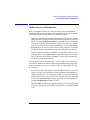
Electrostatic Discharge (ESD) Precautions
Electrostatic charges can damage the integrated circuits on printed circuit
boards. To prevent such damage from occurring, observe the following precautions during board unpacking, installation, and configuration:
•
Stand on a static-free mat.
•
Wear a static strap to ensure that any accumulated electrostatic charge is
discharged from your body to ground.
•
Connect all equipment together, including the static-free mat, static strap,
routing nodes, and peripheral units.
•
Keep uninstalled printed circuit boards in their protective antistatic bags.
•
Handle printed circuit boards by their edges, once you have removed them
from their protective antistatic bags.
Release Document(s)
Please refer to the Release Document(s) you received with your system or
system software for additional information that we may not have been able
to include in this guide at the time of its publication.
Preface-4
Related Manuals
If you are using HP-UX version 10.20, refer to the following manuals for
more information:
•
Model 748 Owner’s Guide (A4511-90607)
•
Using Your HP Workstation (A2615-90003)
•
Installing and Updating HP-UX (B2355-90050)
•
Graphics Administration Guide (B2355-90109)
•
Configuring HP-UX for Peripherals (B2355-90053)
•
HP Visual User Environment User’s Guide (B1171-90079)
•
Managing Clusters of HP 9000 Computers: Sharing the HP-UX
File System (B2355-90038)
•
HP-UX X User Environment User’s Guide
If you are using HP-RT, refer to the following manuals for more information:
•
Application Programming in the HP-RT Environment
•
Driver Writing in the HP-RT Environment
•
ELOG Library Programer’s Guide
•
HP Z5117A PCMCIA Adapter Installation and User’s Guide
•
HP-RT Reference
•
HP-RT Quick Reference
•
HP-RT System Administration Tasks
•
VME Backplane Networking Administration Guide
•
X11 SERVERrt Installation and Configuration Guide
•
Using SNMP in the HP-RT Environment
•
Using STREAMS in the HP-RT Environment
To order manuals, please contact your local sales office.
Preface-5
Revision History
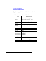
The revision history for each edition of the manual is listed below:
Preface-6
HP Part No.
Edition
Revision History
A4500-90607
E0996
First printing
A4511-90602
E0897
Updated to include Model
744/165L, PMC, and
memory enhancements
A4511-90606
E1199
Updated for new memory
options
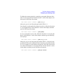
Documentation Conventions
Unless otherwise noted in the text, this guide uses the following symbolic
conventions.
user-supplied values
Italic words or characters in formats and command descriptions
represent values that you must
supply.
sample user input
In examples, information that the
user enters appears in color.
output
Information that the system displays appears in this typeface.
literal values
Bold words or characters in formats and command descriptions
represent commands or keywords
that you must use literally. Pathnames are also in bold.
KEY
Text with a line above and a line
below denotes a key on your keyboard, or a key or button which is
drawn on your workstation’s
graphic display.
(In this manual we refer to the
Enter key. On your keyboard the
key may be labeled either Enter
or Return.)
Preface-7
Questions, Suggestions, or Problems
If you have any questions, suggestions, or problems with our hardware, software, or documentation, please contact your HP Response Center.
Preface-8
Declaration of Conformity
Preface-9
Preface-10
1
Model 744 Board Computer Overview
1-1
Model 744 Board Computer Overview
This chapter introduces the Model 744 Board Computer. Its purpose is to
familiarize you with the board computer and its installation procedure.
The instructions in this chapter assume you are using either the HP-UX or
HP-RT operating system.
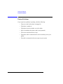
The major sections within this chapter are:
1-2
•
Product Description
•
Installation Overview
•
Supported Products
•
Environmental Requirements
•
Operating System Overview
•
Manuals for System Information
•
Online Sources of Information
•
Installing HP-UX and HP-RT
•
Audio
Model 744 Board Computer Overview
Product Description
Product Description
The HP 9000 Model 744 is a high-performance Precision Architecture board
computer based on the Hewlett-Packard PA-RISC 7300LC technology. It
contains the following key features:
•
Model types (the rt designates models that operate under the HP-RT
operating system - the models are physically the same):
Model 744/132L
Model 744rt/132L
Model 744/165L
Model 744rt/165L
•
VME slot configuration
Single slot
Dual slot (requires PCI Mezzanine Card (PMC) bridge board or
General System Connect (GSC) expansion kit
Three slots (requires PMC bridge and expander boards)
•
CPU PA-RISC PA7300-LC, processor performance
Model 744/132L - 132 MHz
Primary internal cache - 128 KB: 64 KB instruction, 64KB data
Model 744/165L - 165 MHz
Primary internal cache - 128 KB: 64 KB instruction, 64KB data
Secondary cache - 512 KB
•
Clocks
Battery-backed real-time clock
Interval timers (One 32 bit, Two16 bit)
Watchdog timer
1-3
Model 744 Board Computer Overview
Product Description
•
Operating systems
HP-UX 10.20 (or later). The Model 744 typically boots from a hard
disk drive. HP-UX may also be installed from an external DDS or
CD-ROM drive.
If the Model 744 is a client on a LAN, HP-UX can be booted over
the LAN.
HP-RT 2.21 (or later).
•
User interface
CDE or HP VUE graphical user interface (HP-UX only).
•
Compatibility
Source and binary code compatible with Series 700 product family.
•
Monitors
Single or multiple display depending on number of installed
graphics options (on-board and/or external).
Color monitors:
17-inch, resolution 1280 x 1024
19-inch, resolution 1280 x 1024
Terminal (text only) connected to RS-232 port.
•
Optional Graphics Capability
Graphics chip set providing on-board (including accelerated I/O)
graphics.
PMC bridge and expansion adapters each provide two slots for HP
A4979A graphic cards.
HP-RT supports a PMC adapter with an HP A4979A graphics
card when on-board graphics is not used.
1-4
Model 744 Board Computer Overview
Product Description
NOTE:
The HP-RT operating system supports only one graphics display, and HP-UX
10.x supports up to four graphics displays.
•
Main Memory
Single VME slot 744: 64, 128, or 256 MB RAM
Single VME slot 744 with HP-RT: 64 to 256 MB RAM
Dual VME slot 744: 32 to 1024 MB RAM
Dual VME slot 744 with HP-RT operating system: 64 to 756 MB
RAM (Dual slot means an expansion kit must be installed.)
NOTE:
A Model 744 configured for more than one RAM card requires installation of
a PMC bridge board, or a GSC expansion kit, thereby occupying two VME
slots.
Up to four RAM cards may be installed.
When mixing memory card capacities that include 128 or 256 MB
cards, the 128 or 256 MB card(s) must be installed into the lowest
memory slots before adding cards of other capacities.
•
Standard Features
Internal SCSI-2 single-ended bus
2 asynchronous RS-232-C ports (requires a conversion cable)
1 HP parallel port (requires a conversion cable)
1 LAN AUI port (requires a conversion cable)
2 mini-DIN PS/2 ports
1 slot for RAM memory (memory cards can be stacked)
CD-quality audio, supported only by HP-UX and requires a
conversion cable
•
Dual Slot Upgrades
PMC bridge board (with two PMC sites)
GSC Expansion kit (with two GSC sites)
•
3-slot Upgrade
PMC Expander board (with two PMC sites, requires PMC bridge)
ATM Network Card (up to 2, GSC expansion kit required)
1-5
Model 744 Board Computer Overview
Installation Overview
Installation Overview
Chapter 2 provides step-by-step instructions for attaching and installing
accessories in a typical VME card cage, and connecting external devices.
Accessories are products that attach to the computer’s system board. They
must be attached before installing the board computer in a VME card cage.
Devices are products used externally to the board computer. Examples are
keyboards, monitors, and mass storage devices. Other devices are connected
through cables. Depending on your specific application, you may need one
or more accessory and device products. Installation instructions for most
products used directly with your Model 744 Board Computer are explained
in this manual.
Chapter 3 presents the installation tasks required to install and configure
your board computer.
Installation Notes
Your Model 744 Board Computer uses micro-miniature connectors for several interface ports. Cable connectors for these ports are very small, but may
be positioned so that a slight angle exists between them. This situation has
been tested by HP and full functionality is maintained.
CAUTION:
1-6
The Model 744 Board Computer’s P2 connector has a local bus on the userdefined pins. Verify that your VME card cage’s backplane makes no
connections to J2/P2, rows A and C. Refer to IEEE STD 1014-1987, Chapter
7, for more information on use of user-defined pins in VME backplane
connectors.
Model 744 Board Computer Overview
Supported Products
Supported Products
Only products with Hewlett-Packard approved parts, accessories, peripherals, operating systems, and application programs are supported by HewlettPackard. Any product with other than HP approved hardware or software
connected or installed must have the non-HP approved hardware and software removed by the customer before on-site repair is conducted. The following lists describe the products supported by HP.
Accessory Cards
The Model 744 supports the following accessory cards:
•
HP A4219A expansion kit
•
Memory; one or more of the following RAM cards is supported on
either the HP-UX or HP-RT operating system:
HP A4503A 64 MB RAM card
HP A4449A 128 MB RAM card
HP A6005X 256 MB RAM card
•
Mezzanine (GSC expansion kit) cards:
HP J3420A ATM Network Card (supported only by HP-UX)
Typical External Devices
The Model 744 supports the following external devices:
•
LAN transceiver
HP A2670A ThinLAN ETHERNET Transceiver
HP A2671A EtherTWIST Transceiver
•
Speaker; 8 ohm impedance with 1/8-inch sub-miniature
stereo connector (HP-UX only).
1-7
Model 744 Board Computer Overview
Supported Products
Conversion and Standard Cables
Model 744 Board Computers use micro-miniature connectors for several
interface ports and standard connectors for others. You need conversion
cables to connect from the micro-miniature connectors to standard size interfaces. The Model 744 supports the following cables:
•
Conversion cables:
HP A4300A HP parallel; high-density 25-pin to
standard 25-pin F
HP A4301A RS-232; high-density 9-pin to standard 9-pin M
HP A4302A audio; high-density 9-pin to stereo line-in
HP A4303A LAN; high-density 15-pin to 15-pin AUI
HP A4223A video; high-density 15-pin to standard 15-pin,
HP A4305A video; high-density 15-pin to EVC connector
HP A4167A video; standard 15-pin to EVC connector (for use with
optional GSC 8-plane graphics card and EVC monitor
•
Standard cables:
HP K2296 SCSI; high-density 50-pin to standard bail lock
HP 92284A HP parallel; 25-pin M to 25-pin M
HP 24542G RS-232 terminal cable; 9-pin F to 25-pin M
HP 24542M RS-232 modem cable; 9-pin F to 25-pin F
Keyboard and Mouse
The Model 744 supports the following:
1-8
•
HP A2840A keyboard with mini-DIN connector
•
HP A2839A mouse with mini-DIN connector
Model 744 Board Computer Overview
Environmental Requirements
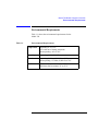
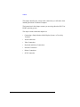
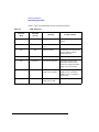
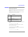
Environmental Requirements
Table 1-1 shows the environmental requirements for the
Model 744.
Table 1-1
Environmental Requirements
Temperature
Operating: 0° to 55°C;
10°c/min rate of change maximum
Non-operating: -40° to 70°C
Humidity
Operating: 40°C: 95% RH max
Altitude
Operating: 4,600m (15,000 ft) to 40°C
Non-operating: 15,300m (30,000 ft) to 70°C
Air Flow
150 linear feet per minute, 0° to 35°C
200 linear feet per minute, 35° to 55°C
1-9
Model 744 Board Computer Overview
Environmental Requirements
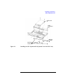
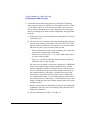
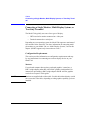
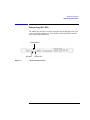
CAUTION:
Integrated circuit case and junction temperatures must not exceed those
shown in Figure 1-1.
Tj = 95 (744/132L
= 102 (744/165L)
Tj = 85
Tj = 100
Tj = 85
Tc= 75
Tj = Maximum junction temperature in degrees centigrade
Tc = Maximum case temperature in degrees centigrade
Figure 1-1
Model 744 Board Computer (Top View)
NOTE:
The Model 744 should only be operated in an environment that is free from
conductive pollution, including dry non-conductive pollution that may
become conductive due to expected condensation.
1-10
Model 744 Board Computer Overview
Operating System Overview
Operating System Overview
The Model 744 can be used with either of two operating systems, HP-UX or
HP-RT. This manual provides basic information you will need for booting
and running HP-UX. It also provides some overview information for HP-RT.
The Model 744 uses the standard HP-UX 10.20 or later operating system, a
highly versatile system for multitasking, running your application programs,
and performing a variety of development tasks. Refer to HP-UX System
Administration Tasks for detailed installation and operation procedures for
HP-UX.
The Model 744rt uses HP-RT 2.21 or later, a real-time operating system.
HP-RT is HP’s real-time operating system for PA-RISC VME board computers. It is a runtime-oriented product based on industry-standard application programming interfaces. HP-RT is designed around the real-time
system principles of determinism (predictable behavior), responsiveness,
user control, and reliability for “mission-critical” applications.
Refer to HP-RT System Administration Tasks for detailed installation and
operation procedures for HP-RT.
The HP-RT development environment consists of the following:
•
An HP-UX host system (for example, a Model 748i), running the supported HP-UX operating system, with CDE, X Window System, or HP
VUE installed.
•
DDS-format tape drive or CD ROM for loading HP-RT on the host
system.
•
The HP-RT target system (such as a Model 744rt).
1-11
Model 744 Board Computer Overview
Manuals for System Information
Manuals for System Information
HP-UX
After you have completed the installation procedures in this book, you may
consult the following sources for further information:
•
For HP-UX administration information, see HP-UX System Administration Tasks.
•
For a quick reference to commonly-used HP-UX commands, see the
appendix in Using HP-UX.
•
HP VUE or CDE is the default interface for HP-UX. At some point,
you may want to interact with the Model 744 using CDE or HP VUE
via the LAN, with an X Window System display. As a simpler window
alternative, you can also use the X Window System by itself. All interfaces are included in HP-UX. For further information, refer to Using
the X Window System, Using HP-UX, CDE User’s Guide, or HP VUE
User’s Guide.
The following manuals are also useful:
•
If you have not yet installed your HP-UX OS, see Installing HP-UX.
•
For troubleshooting HP-UX, see Chapter 6 of this manual, and the
manual Solving HP-UX Problems.
•
For VME configuration information, refer to the appropriate VME
manual for your operating system.
HP VUE
For information on using and configuring the HP VUE interface with HPUX, see HP VUE User’s Guide. For information on installing HP VUE, refer
to HP VUE Installation Guide.
HP CDE
For information on using and configuring the CDE interface with HP-UX,
see CDE User’s Guide. For information on installing CDE, refer to CDE
Installation Guide.
1-12
Model 744 Board Computer Overview
Online Sources of Information
Online Sources of Information
HP-UX is designed so that you can access many sources of information
without leaving your system. Most of these information sources are accessible through the shell command line on a character terminal.
•
Man pages: The HP-UX information found in HP-UX Reference is online
and accessible by clicking on the Toolbox button at the right of your Front
Panel, or by entering man command on a command line, where command
is the name of the HP-UX command or routine you want to get information on. If you’re not sure of the command name, you can enter man -k
keyword, where keyword is a likely topic word to search on. This results
in a display listing commands having the keyword in their description.
Similar reference information on HP-RT, found in HP-RT Reference, can
be displayed by entering rtman name on your HP-UX host system, where
name is the name of the HP-RT command, system call, or function call
you want to get information about.
On your HP-UX system, there are also a variety of files which contain version-specific information. These will be useful in administering and configuring cards and devices for your version of HP-UX. Among these files are
the following:
•
Release Notes: This is the online version of the Release Notes which come
with your system. It contains all the latest information, undocumented
changes, and bug fixes for your release of HP-UX. It also contains information on the current version of HP VUE. The Release Notes document
resides in the /usr/share/doc directory, named by its release number; for
example, 10.20RelNotes for HP-UX 10.20.
•
HP-UX and HP VUE Help. For graphics displays, extensive help information on the operating system and the visual interface is included with HP
VUE.
1-13
Model 744 Board Computer Overview
Online Sources of Information
•
Newconfig: The directory /usr/newconfig/etc contains information and
new versions of HP-UX product configuration files, as well as shell
scripts which may have been customized on your system. The contents of
this directory will vary depending on which products you have loaded
onto your system. In most cases, old versions of these files, in their regular
locations in the file system, are not overwritten by the update process.
In HP-RT, you will find an HP-RT specific README file in /opt/HP-RT/
etc/newconfig/, on the HP-UX host system. This file contains version-specific information.
1-14
Model 744 Board Computer Overview
Installing HP-UX and HP-RT
Installing HP-UX and HP-RT
For procedures to install and configure HP-UX, refer to HP-UX System
Administration Tasks.
For information on clusters, refer to Managing Clusters of HP-UX Computers, and HP VUE User’s Guide.
For procedures to install and configure HP-RT, refer to HP-RT System
Administration Tasks.
1-15
Model 744 Board Computer Overview
Audio
Audio
HP-UX includes audio software comprising an audio editor, Audio Application Program Interface (AAPI), and some sample programs. Audio output is
available through the audio port on the front panel of the Model 744. For
highest quality audio, an external headphone set or speaker is recommended.
Audio is implemented using a CODEC (coder-decoder) combining CDquality stereo audio-digital converters for microphone and line-input levels.
The input sampling rate and format are programmable, as are the input gain
and output attenuation.
A 1/8-inch mini-jack is used for the speaker output connection. The remaining audio signals are via a 9-pin D-sub connector. Output impedance is nominally 8 ohms, but higher impedance devices can also be driven.
For information on programming for audio, refer to Using the Audio Developer’s Kit (B2355-90069) and the man page audio.
1-16
2
Installing Accessories
2-1
Installing Accessories
This chapter describes the accessories you can install on the Model 744
Board Computer and tells you how to install them.
The instructions in this chapter assume you are using either the HP-UX or
HP-RT operating system.
The major sections within this chapter are:
2-2
•
Tools Required and Preliminary Procedures
•
Safety Precautions
•
Memory
•
GSC Expansion Kit
•
GSC Mezzanine Cards
•
PMC Bridge and Expansion Boards
Installing Accessories
Tools Required and Preliminary Procedures
Tools Required and Preliminary Procedures
Tools Required for Installation
All field replaceable parts can be accessed with these tools:
Static grounding wrist strap
No. 1 Pozidriv screwdriver
Small flat-tipped screwdriver
5mm (3/16-inch) nutdriver (RAM standoffs require this tool)
Preliminary Procedures
Perform the following steps before installing or removing accessories:
1 Exit application programs.
2 Shut down the operating system and power off the VME chassis. (See
Chapter 5 for detailed instructions.)
3 Remove all cables connected to the board computer.
4 Set up a static-free place on which to work.
2-3
Installing Accessories
Safety Precautions
Safety Precautions
It is essential to practice safety precautions when working with any electrical
or electronic products. Following these safety precautions can help protect
both you and the equipment from injury and possible permanent damage.
Whether the ICs are installed on a printed circuit board or lying on a table,
integrated circuit components can be damaged by electro-static discharge.
Static charges can build up in people to a potential of several thousand volts
by simply walking across a room.
Protect integrated circuits by:
•
Using a static-free work place and wearing clothes that do not hold
static charges before handling any of the workstation’s PC boards.
•
Unplugging the power supply before removing or installing a part.
•
Touching sheet metal with your fingers before touching the printed
circuit assembly.
If the assembly is not going to be re-installed, place the assembly in an antistatic bag and set it aside. Following these precautions extends the life of the
computer products you maintain.
2-4
Installing Accessories
Memory
Memory
This section provides step-by-step instructions for installing RAM cards in
the Model 744. The Model 744 memory kit contains a memory card, a set of
standoffs, a set of screws, and a wrist strap.
Preliminary Requirements
Perform the following steps before you install a RAM card into the
Model 744:
1 If the Model 744 is already installed in your system chassis, you must remove it. See Chapter 3 of this manual for instructions on removing and
replacing the Model 744.
2 Place the Model 744 on a static-free mat on a clean, level surface.
RAM Card Installation
For a Model 744 in a single slot configuration (no expansion adapter
installed), only one RAM can be installed. In a two-slot configuration, up to
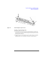
four RAM cards may be stacked. Use these steps and Figure 2-1 to install the
RAM cards:
NOTE:
When mixing memory card capacities that include 128 or 256 MB cards, the
128 or 256 MB card(s) must be installed into the lowest memory slots before
adding cards of other capacities.
1 Begin with the Model 744 placed so that you face the front bezel.
2 If the Model 744 has RAM card(s) already installed, remove the screws
that secure the topmost RAM card, and then install the new standoffs that
came with your RAM card onto the topmost card (see Figure 2-1).
3 Hold the RAM card you are installing so that the conferred corner is the
upper-left corner (see Figure 2-1).
4 While placing the new RAM card over the CPU or topmost installed card,
align the holes in the RAM card with the spacers/standoffs underneath it.
2-5
Installing Accessories
Memory
5 Properly align the connectors by slightly rotating the RAM card until you
can feel the connectors fit together.
6 Gently and evenly push on the top of the connectors with both of your
thumbs until the RAM cards are about 1/3 seated.
7 After the connectors are 1/3 seated, continue to push evenly with your
thumbs, while pushing harder. The connectors will fully snap together.
8 Examine the connector seating from both sides of the RAM card to ensure
there are no gaps between the RAM card connectors and the connectors
underneath it.
9 Secure the topmost card with the screws you removed in Step 2.
2-6
Installing Accessories
Memory
RAM Card Removal
When removing RAM cards from the Model 744 CPU or the RAM card
stack, remove the cards one at a time. Carefully lift the card by the edge near
the connectors. Do not try to pry the card up with a tool.
Figure 2-1
Installing RAM Cards
2-7
Installing Accessories
GSC Expansion Kit
GSC Expansion Kit
The GSC expansion kit consists of two parts: the adapter fixture and the
front panel extension. This section provides step-by-step instructions for
installing the GSC expansion kit onto the Model 744.
Preliminary Requirements
Perform the following steps before installing the adapter (GSC expansion
kit) fixture onto your Model 744 Board Computer:
1 If the Model 744 Board Computer is already installed in your system chassis, you must remove it. See Chapter 3 of this manual for instructions on
removing and replacing the Model 744.
2 Place the Model 744 on a static-free mat on a clean, level surface.
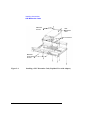
GSC Expansion Kit Installation
Follow these steps to install the expansion kit onto the Model 744:
1 Place the expansion adapter so that you line up the four M2.5x12 screw
holes that flank the DIN connectors. See Figure 2-2.
2 Insert the four M2.5x12 screws one at a time, finger tighten, then snug
down with a screwdriver. Do not overtighten.
3 Insert the two M2.5x6 screws, finger tighten, then snug down with a
screwdriver.
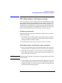
4 Remove the copper EMI gasketing from the front panel of the Model 744
Board Computer.
5 Place the panel extension over the front panel so that the four tabs on the
bottom of the extension panel line up and slip into their respective slots on
the top of the front panel.
6 Insert the four front panel screws, finger tighten, then snug down with a
screwdriver, as shown in Figure 2-3.
2-8
Installing Accessories
GSC Expansion Kit
GCS Card
GSC
Expansion
Kit
M2.5X6
Screws
M2.5X12
Screws
Figure 2-2
Installing the GSC Expansion Kit (Exploded View with GSC Card)
2-9
Installing Accessories
GSC Expansion Kit
Figure 2-3
2-10
Adding the Front Panel Screws
Installing Accessories
GSC Mezzanine Cards
GSC Mezzanine Cards
Installing GSC Mezzanine Cards
This section provides step-by-step instructions for installing GSC mezzanine
cards into your Model 744 Board Computer.
Preliminary Requirements
Perform the following steps before you install a GSC card:
1 The Model 744 Board Computer must already have a GSC expansion kit
installed.
2 If the Model 744 Board Computer is already installed in your system chassis, you must remove it. See Chapter 3 of this manual for instructions on
removing and replacing the Model 744.
3 Place the Model 744 Board Computer on a static-free mat on a clean, level
surface.
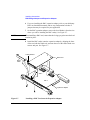
GSC Mezzanine Card Installation
Follow these steps to install a GSC card onto your Model 744 Board Computer:
1 Working from the back of the Model 744 Board Computer, you can install
GSC graphics cards into either the right-hand or center position, shown in
Figure 2-4.
2 Using Figure 2-4 as a guide, position a card and line up its connector over
the GSC connector on the board computer.
3 Press the card down to seat the connectors.
4 Insert the two M2.5x6 screws that hold the GSC card to the adapter fixture
and screw them into place.
5 Insert the two M2.5x5 screws that hold the card to the front panel expansion plate and screw them into place.
2-11
Installing Accessories
GSC Mezzanine Cards
MX2.5X6
Screws
GSC
Mezzanine
Card
GSC Connectors
MX2.5X5
Front Panel
Screws
Figure 2-4
2-12
Installing a GSC Mezzanine Card (Exploded View with Adapter)
Installing Accessories
PMC Bridge Adapter and Expansion Adapter
PMC Bridge Adapter and Expansion Adapter
This section provides step-by-step instructions for installing the PMC bridge
and expansion adapters onto the Model 744 board computer. When the PMC
bridge adapter is installed onto the Model 744, the result is a two-board
assembly that is the installed into your VME card cage. When both the PMC
bridge and expansion adapters are installed onto the Model 744, the result is
a three-board assembly that is the installed into your VME card cage.
Preliminary Requirements
Perform the following steps before installing the adapters onto your Model
744 Board Computer:
1 If the Model 744 is already installed in your system chassis, you must remove it. See Chapter 3 of this book for instructions on removing and replacing the Model 744 Board Computer.
2 Place the Model 744 on a static-free mat on a clean, level surface.
PMC Bridge Adapter and Expansion Adapter Installation
1 Refer to your third party PMC card installation manual, and set any configuration switches or jumpers that may be required for your application.
2 On the PMC bridge adapter, at the sites where you will be installing the
PMC card(s), remove the two screws that secure the bezel blank(s), and
remove the blanks. See Figure 2-5.
NOTE:
When installing a PMC card, ensure that the O-ring type gasket near the bezel
remains in place.
3 Install the PMC card(s) onto the bridge adapter by aligning the front of the
card with the front bezel, and on the rear of the card with the connectors
and post. See Figure 2-5. There are four screws that secure the PMC card
from the bottom of the bridge adapter.
2-13
Installing Accessories
PMC Bridge Adapter and Expansion Adapter
O-Ring Gasket
PMC Card
Bezel
blank
Site 2
Site 1
Bridge Adapter
Figure 2-5
2-14
Installing a PMC Card onto the PMC Bridge Adapter
Installing Accessories
PMC Bridge Adapter and Expansion Adapter
4 Remove the copper EMI gasketing from the front panel of the board computer.
5 Install the PMC bridge adapter onto the board computer as shown in Figure 2-6. There are four screws that secure the front bezel, and four screws
that secure the VME connectors.
PMC Bridge Adapter
with 2 PMC Cards Installed
Front Bezel Screws (4)
Figure 2-6
Connector
Screws (4)
Installing the PMC Bridge Adapter onto the Board Computer
2-15
Installing Accessories
PMC Bridge Adapter and Expansion Adapter
6 If you are installing the PMC expansion adapter, refer to your third party
PMC card installation manual, and set any configuration switches or
jumpers that may be required for your application.
7 On the PMC expansion adapter, remove the bezel blank(s) from the sites
where you will be installing the PMC card(s). See Figure 2-7.
NOTE:
When installing a PMC card, ensure that the O-ring type gasket near the bezel
remains in place.
8 Install the PMC card(s) onto the expansion adapter by aligning the front
of the card with the front bezel, and onto the rear of the card with the connectors and post. See Figure 2-7.
O-Ring Gasket
PMC Card
Bezel
blank
Site 4
Site 3
Expansion Adapter
Figure 2-7
2-16
Installing a PMC Card onto the Expansion Adapter
Installing Accessories
PMC Bridge Adapter and Expansion Adapter
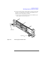
9 Remove the four screws from bridge adapter VME connectors, as shown
in Figure 2-8.
10 Using a small screwdriver or razor, remove the copper EMI gasket on the
front bezel of the bridge adapter, as shown in Figure 2-8.
Bridge Adapter
VME Connectors
Screws (4)
Bridge Adapter
Front Bezel
EMI gasket
Figure 2-8
Removing Bridge Adapter Screws and EMI Gasket
2-17
Installing Accessories
PMC Bridge Adapter and Expansion Adapter
11 Screw the four threaded standoffs into the bridge adapter’s VME connectors.
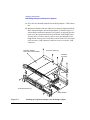
12 Making sure that the connector and bezels are properly aligned, install the
PMC expansion adapter onto the bridge adapter, as shown in Figure 2-9.
Ensure that the interboard connector seats properly by applying pressure
to the top of the expansion board and to the bottom of the bridge board.
You may have to remove memory cards to access the underside of the
bridge board. There are two screws that secure the front bezel, four standoffs between the VME connectors, and four screws to secure the VME
connectors.
Expansion Adapter
with 2 PMC Cards Installed
Connector Screws (4)
Interboard
Connector
Standoffs (4)
Front Bezel Screws (2)
Bridge Adapter
Figure 2-9
2-18
Installing the Expansion Adapter onto the Bridge Adapter
Installing Accessories
PMC Bridge Adapter and Expansion Adapter
13 If you have installed a PMC expansion adapter, resulting in a three board
assembly, we recommend that you install the ejector handle sleeves included in your kit. The procedure is as follows:
a Remove the logo and model labels from the ejector handles on your
board computer, as shown in Figure 2-10.
Model label
Logo label
Figure 2-10
Removing Ejector Handle Labels
2-19
Installing Accessories
PMC Bridge Adapter and Expansion Adapter
b Slide the sleeves over each set of handles, as shown in Figure 2-11.
Sleeves
Figure 2-11
2-20
Installing Ejector Handle Sleeves
Installing Accessories
PMC Bridge Adapter and Expansion Adapter
c Thread the springs included in the kit into the ejector handles on the
PMC expansion board, and with the springs compressed, slide the labels from the Model 744 Board Computer into the sleeves, as shown
in Figure 2-12.
NOTE:
To properly identify the board computer model and manufacturer, we
strongly advise that the original labels from the board computer be placed into
the ejector handle sleeves.
Labels
Springs
Figure 2-12
Installing the Springs and Labels
2-21
Installing Accessories
PMC Bridge Adapter and Expansion Adapter
14 Remove the VME slot cover plate(s) from the VME card cage, as required
to open the slots the new assembly will occupy.
15 Insert the Model 744 with the attached PMC adapter(s) into card cage
slots until the they seat properly and the front panels are flush against the
card cage.
CAUTION:
Do not tighten any captive screws until you have started to thread each
captive screw into its hole.
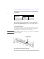
16 Engage all captive screws before tightening each screw of the board computer/PMC assembly. See Figure 2-13
Captive Screws
Ejector Handles
Figure 2-13
2-22
Installing the Board Computer with PMC into VME Card Cage
Installing Accessories
PMC Bridge Adapter and Expansion Adapter
17 Plug in the power cord(s), and then turn on the power for the VME card
cage and boot the operating system.
18 Log in as root and use the SAM utility to configure the HP-UX kernel for
PCI support. (PMC cards require PCI drivers in the kernel.)
19 When SAM has started, choose the Kernel Configuration ->
menu.
20 From the Kernel Configuration menu, choose Drivers
21 From the Drivers menu, select GSCtoPCI Driver.
22 Go to the Actions menu and select Create a New Kernel.
23 When the new kernel is built, SAM asks if you want to move the kernel
into place and reboot. Choose Yes.
The system reboots with the PCI driver loaded.
2-23
Installing Accessories
PMC Bridge Adapter and Expansion Adapter
2-24
3
Typical Installation in a
VME Card Cage
3-1
Typical Installation in a VME Card Cage
This chapter describes the Model 744 Board Computer and tells you how to
install it.
The instructions in this chapter assume you are using either the HP-UX or
HP-RT operating system.
The major sections within this chapter are:
3-2
•
Configuring the VME Card Cage
•
Keyboard and Mouse
•
Board Computer Installation
•
Non-HP Installation
•
HP Installation (Other than in Primary CPU)
•
Board Computer Removal
Typical Installation in a VME Card Cage
Configuring the VME Card Cage
Configuring the VME Card Cage
This section provides step-by-step instructions for configuring the VME
card cage.
Use Table 3-1 to determine the configuration for the VME card cage.
Table 3-1
Determining the VME Card Cage Configuration
If your Model 744
Board Computer...
has an HP A4219A Expansion Kit
attached, and will be installed in an
HP 9000 Series 700 Model 748 VME
System,
Then...
the Model 744 Board Computer must
be installed in either:
Slots 1 and 2; the bottom two slots
Slots 3 and 4, or any other highernumbered slot pair
See the CAUTION text.
CAUTION:
is single-board configured,
the VME card can be installed in any
slot.
was removed from its VME card cage
to change or add accessories,
see “Model 744 Installation” on page
3-8.
is going to be installed for the first
time in a VME card cage,
follow the step-by-step instructions
below.
In the Model 748 card cage, slots 1 and 2 are powered by the bottom power
supply. Slots 3 through 8 are powered by the top power supply. A Model 744
Board Computer with its expansion kit attached, installed in slots 2 and 3, will
cause the power supplies to shut down.
To determine the board computer’s power needs, follow these instructions:
1 Determine the board computer’s current requirements from the Computer
Current Requirements Worksheet (Table 3-4).
3-3
Typical Installation in a VME Card Cage
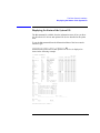
Configuring the VME Card Cage
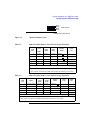
2 To determine the maximum current usage of the Model 744 memory
cards, either use Figure 3-1 and Table 3-2 (for Model 744/132L) or Table
3-3 (for Model 744/165L). You must work with the worst case power
draw to correctly determine power usage. Determine worst case power
draw by examining active memory bank configurations, using the following steps:
a Examine your memory card configuration, noting which size card is in
each memory slot.
b The worst case active memory bank configuration depends on the slot
position of the memory cards, and the size of the cards. The 32 MB
memory card has two banks per card, and the 16, 64, and 128 and 256
MB cards each have only one memory bank per card.
•
When 32 MB cards are used as a pair in memory slots 2 and 3 they
can use three memory banks concurrently.
•
When used as a pair in slots 0, 1, or 2, the 32 MB cards can have
two active memory banks.
•
The 16, 64, 128 and 256 MB cards each have only one memory
bank that is active at any one time.
The worst case power draw is when your system has two 32MB cards
in slots 2 and 3 (these banks would be considered active, all other
memory cards/banks would be considered inactive). The next worst
case is a 256 MB card in any slot (all other memory cards in the system would be inactive), followed by a 64 MB card in any slot (all
other memory cards in the system would be inactive), followed by
two 32 MB cards in slots 0, 1, or 2 (all other memory cards in the system would be inactive), followed by a 128 MB card in any slot, and
finally a 16 MB card in any slot (all other memory cards in the system
would be inactive).
c Inactive memory banks are those banks on cards in your configuration
in addition to the worst case active memory banks, and must also be
added to the calculation.
d Fill in the information in Table 3-2 or Table 3-3.
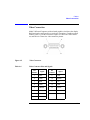
3-4
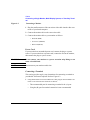
Typical Installation in a VME Card Cage
Configuring the VME Card Cage
Slot 3
Slot 2
Slot 1
Slot 0
Memory Slots
Model 744 System Board
Figure 3-1
Model 744 Memory Slots
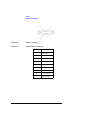
Table 3-2
Model 744/132L Memory Card Current Usage Worksheet
Memory
Card
Size
First
Active
32 MB2
1.15 A
1.15 A
1.15 A
0.05A x ___
_________
64 MB
2.6 A
N/A
N/A
0.1 A x ___
_________
128 MB
1.45A
N/A
N/A
0.07 A x ___
_________
16 MB
1.15 A
N/A
N/A
0.05A x ___
_________
256 MB
2.90 A
N/A
N/A
0.14 A
_________
Bank
1
Second
Active
Bank
Third
Active
Bank
Inactive
Banks
Total memory current
Table 3-3
Memory
Card
Size
Totals
(+5V)
_________
1
Choose the worst case active bank(s) for your calculation.
2
Slot positions and amount of 32MB cards determine the number of active banks.
Model 744/165L Memory Card Current Usage Worksheet
First Active
Bank1
0.53 A (+12V)
32 MB2
64 MB
1.2 A (+12V)
128 MB
1.45 A (+5V)
16 MB
0.53 A (+12V)
256 MB
2.90 A
Total memory currents
Second
Active
Bank
Third
Active
Bank
Inactive
Banks
Totals
(+12V)
0.53 A
0.53 A
0.023A x ___
_______
N/A
N/A
N/A
N/A
N/A
N/A
N/A
N/A
0.05 A x ___
0.07 A x ___
0.023A x ___
0.14 A
_______
Totals
(+5V)
______
_______
_______
_______
_______
1 Choose the worst case active bank(s) for your calculation.
2 Slot positions and amount of 32MB cards determine the number of active banks.
3-5
Typical Installation in a VME Card Cage
Configuring the VME Card Cage
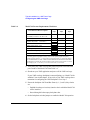
Table 3-4
Model 744 Current Requirements Worksheet
Each Model 744 Board Computer
If 132 MHz, current for +5V dc is 4.7A 1
If 165 MHz, current for +5V dc is 6.3A
RAM cards (see Table 3-2 or Table 3-3)
Graphics subsystems
2
+5V dc
Amps
+12V dc
Amps
0.1A
-12V dc
Amps
0.1A
______
________
x 0.9A each =
FWD SCSI GSC card x 0.7A each =
HCRX graphics board 2.0A
PMC bridge adapter 0.6A
PMC cards on bridge adapter 3
________
________
Totals for Model 744 board computer
________
________
1. Does not include on-board graphics, if installed.
2. On-board graphics and graphics accessory cards are each separate graphics subsystems.
3. PMC cards may also draw +3.3 current that is provided through the +5 on the bridge adapter.
The +3.3 current FOR ALL PMC CARDS ON THE BRIDGE ADAPTER AND EXPANSION
ADAPTER (do not include other expansion adapter currents) must be entered into the +5 column
after multiplying the +3.3 current by .75 to convert to the actual +5 current draw.
3 Verify that your VME card cage has sufficient power to meet the total
power needs of the Model 744 from Table 3-4.
4 Shut down your VME application and power off the VME card cage.
If your VME card cage backplane is autoconfiguring, see “Model 744 Installation” later in this chapter. If not, refer to your VME card cage documentation for configuring the VME backplane. Go to Step 5.
5 Ensure the backplane IACK and Bus Grant (0, 1, 2, and 3) daisy-chains
are:
•
Enabled from the previous slot(s) into the slot in which the Model 744
will be installed.
•
Passed through all other empty backplane slots.
6 Set the backplane switches/jumpers to enable the Model 744 operation.
3-6
Typical Installation in a VME Card Cage
Keyboard and Mouse
Keyboard and Mouse
This section provides step-by-step instructions for connecting a keyboard
and mouse to your Model 744.
1 Unpack your new keyboard and place it near your Model 744.
2 Plug the keyboard cable connector into your Model 744 at the PS/2 connector labeled PS/2 0 Kbd.
NOTE:
The keyboard must be connected to PS/2 0 to be operational.
3 Unpack your new mouse and locate the mouse’s black rubber ball in the
mouse box.
4 Remove the ball plate from the bottom of the mouse. Insert the ball and
replace the ball plate.
5 Plug the mouse cable connector into your Model 744 at the PS/2 connector labeled PS/2 1.
3-7
Typical Installation in a VME Card Cage
Model 744 Installation
Model 744 Installation
Tools Required
Model 744 installation requires the following tools:
Tool
Used For
Static grounding wrist strap
(supplied with the installation kit)
Preventing static discharge problems
No. 1 Pozidriv screwdriver
Attaching accessory cards
5 mm (3/16 inch) nutdriver
Attaching accessory cards
Light-duty flat-tipped screwdriver
Attaching accessory cards
Preliminary Requirements
Perform the following procedure before you install the board computer into
the VME card cage:
1 Read the steps in “Configuring the VME Card Cage,” earlier in this chapter.
Installing a Single-Slot Model 744 into an HP Card Cage
Follow these steps to install the Model 744 into the VME card cage:
1 Position the board computer at the desired slot and slide it into the card
cage until it seats properly and the front panel is flush against the card
cage.
2 Push both ejector levers in until they are flush with the front panel.
3 Engage and tighten the captive screws (labeled 1 and 2 in Figure 3-2) at
each end of the board computer. These screws hold the computer in the
VME card cage.
3-8
Typical Installation in a VME Card Cage
Model 744 Installation
3
1
4
2
Figure 3-2
Board Computer Captive Screws
Installing a Dual-Slot Model 744
1 Put the Model 744 at the desired slot. Position and slide it into the card
cage until it seats properly with the front panel and front panel extension
flush against the card cage.
2 Engage all captive screws (labeled 1 and 2, 3 and 4, in Figure 3-2) before
tightening each screw of the Model 744 and the extension panel(s).
3-9
Typical Installation in a VME Card Cage
Non-HP Installation
Non-HP Installation
The Model 744 Board Computer’s P2 connector has a local bus on userdefined pins. Verify that your VME card cage backplane makes no connections to J2/P2, rows A and C.
Refer to Chapter 7 of IEEE STD 1014-1987 for more information on userdefined pins used in VME backplane connectors.
3-10
Typical Installation in a VME Card Cage
HP Installation (Other Than Primary CPU)
HP Installation (Other Than Primary CPU)
The Model 744 Board Computer’s P2 connector has a local bus on userdefined pins. The VME slot used by the Model 744 must make no connections to J2/P2, rows A and C.
Refer to IEEE STD 1014-1987, Chapter 7, for more information on userdefined pins used in VME backplane connectors.
3-11
Typical Installation in a VME Card Cage
Model 744 Removal
Model 744 Removal
Tools Required
Model 744 removal requires the following tools:
Tool
Used For
Static grounding wrist strap
Preventing static discharge problems
Light-duty flat-tipped screwdriver
Loosening card cage screws
Preliminary Requirements
Perform the following procedure before you remove the board computer
from the VME card cage:
1 Read the steps in “Turning Off the System,” in Chapter 5.
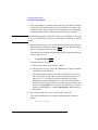
Removing a Model 744
Follow these steps to remove the Model 744 from a VME card cage:
1 Loosen the captive screws at each end of the board computer that hold the
computer in the VME card cage (in Figure 3-3, the screws are labeled 1
and 2 for a single-slot board computer, or 1 through 4 for a dual-slot board
computer).
2 Pull both ejector levers out until the board ejects from the card cage.
3-12
Typical Installation in a VME Card Cage
Model 744 Removal
3
1
4
2
Figure 3-3
Board Computer Captive Screws
3-13
Typical Installation in a VME Card Cage
Model 744 Removal
3-14
4
Cables
4-1
Cables
This chapter describes the various cable connections you will make when
installing the Model 744 Board Computer.
The instructions in this chapter assume you are using either the HP-UX or
HP-RT operating system.
The major sections within this chapter are:
4-2
•
Connecting a Single Monitor, Multi-Display System, or Text-Only
Terminal
•
Audio Connection
•
Video Connection
•
Keyboard and Mouse Connections
•
Network Connection
•
Printer Connections
•
SCSI Connection
Cables
Introduction
Introduction
This chapter discusses connecting cables to one of the following ports on
your Model 744 Board Computer from a peripheral or accessory:
•
Text terminal (RS-232) connection
•
An audio connection
•
A video (graphics circuit) connection
•
A keyboard or mouse (PS/2 ports) connection
•
A Network (AUI LAN) connection
•
Printer (HP parallel and RS-232) connections
•
A SCSI port connection
PS/2
0
PS/2
1
Kbd
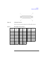
Figure 4-1 shows the front panel connectors for the Model 744.
SE SCSI
Figure 4-1
Model 744 Front Panel Connectors
4-3
Cables
Connecting a Single Monitor, Multi-Display System, or Text-Only Terminal
Connecting a Single Monitor, Multi-Display System, or
Text-Only Terminal
The Model 744 typically uses one of two types of display:
•
CRT-based color monitor connected to a video port
•
Terminal connected to a serial port
Depending on your operating system, the Model 744 supports a maximum of
four monitors at the same time. For more information on connecting multiple monitors to your Model 744, see “Multi-Display Systems,” later in this
chapter. (HP-RT supports only one monitor at a time.)
Configuration Requirements
This section provides information on configuration requirements and stepby-step instructions for connecting one or more display devices to your
Model 744.
Monitors
If your board computer does not have on-board graphics, it must have a
PMC bridge adapter and an HP A4979 PMC graphics card installed. For
instructions on installing a PMC bridge adapter and HP A4979A graphics
card refer to Chapter 2 of this guide.
NOTE:
4-4
Monitors are supplied with a video cable. Use this cable either directly or with
the conversion video cable, depending on what graphics capability you have
installed.
Cables
Connecting a Single Monitor, Multi-Display System, or Text-Only Terminal
Table 4-1 lists the video conversion cables required to connect a monitor to a
video connector.
Table 4-1
Monitor Conversion Cables Required
Graphics Type
On-board graphics
Cable Type from Monitor
Standard 15-pin EVC connector
connector
A4223A
A4305A
Multi-Display Systems
HP-UX 10.20 ACE and later supports up to four monitors simultaneously.
See the Graphics Administration Guide (B2355-90109) for more information about setting up multiple displays.
Connecting the Monitor
This section provides step-by-step instructions for connecting a monitor to
your Model 744 Board Computer with on-board graphics or PMC graphics.
Refer to Figure 4-2 for help when connecting your monitor.
CAUTION:
Some CRT-based monitors are heavy. Use caution when lifting and
unpacking the monitor.
On-Board Graphics
Connector
Note: On-board connectors require conversion cable.
4-5
Cables
Connecting a Single Monitor, Multi-Display System, or Text-Only Terminal
Figure 4-2
Connecting a Monitor
1 Plug the small connector of the conversion video cable into the video connector of your board computer.
2 Connect the monitor cable to the conversion cable.
3 Connect the monitor cable to your monitor as follows:
•
Red to R (RED)
•
Green to G (GREEN)
•
Blue to B (BLUE)
Power Cord
If your monitor has an attached power cord, connect the plug to a power
source. If your monitor has a separate cord, connect the cord to the monitor,
then connect the plug to a power source.
WARNING:
Do not connect your monitor to a power extension strip. Doing so can
cause a shock hazard.
NOTE:
Do not turn on your monitor at this time.
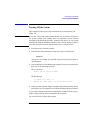
Connecting a Terminal
This section provides step-by-step instructions for connecting a terminal to
your Model 744 Board Computer. Refer to Figure 4-3.
1 Using the HP A4301A conversion RS-232C Cable, plug its micro-miniature connector to one of the RS-232 connectors as follows:
4-6
•
The recommended port for connecting a terminal is the (A) port.
•
Using the (B) port for terminal connection is not recommended.
Cables
Connecting a Single Monitor, Multi-Display System, or Text-Only Terminal
NOTE:
Use of the (B) port requires that VME Services software be installed in the
kernel under HP-UX. The (B) port is not supported during “cold installs” of
HP-UX because VME Services is not installed in the “install kernel”.
RS-232 (A)
RS-232 (B)
Figure 4-3
Connecting a Terminal to the RS-232 Ports
2 Plug the standard end of the conversion cable into the appropriate connector of RS-232 serial cable HP 24525G.
3 Plug the other end of the serial cable into the serial connector on the terminal.
Once you have connected and powered on your terminal and board computer, you may need to reconfigure your board computer for the terminal to
be the console (see Appendix A).
4-7
Cables
Audio Connection
Audio Connection
Model 744 Board Computers provide compact disc-quality audio input and
output in stereo with a 16-bit coder-decoder (CODEC) over a frequency
range of 25-20,000 Hz. Output is provided by a small internal speaker and a
stereo headphone mini-plug (8 ohms impedance). Input is provided by a stereo line-in and mono microphone mini-plugs.
The CODEC combines CD quality stereo A/D converters for microphone
and line input levels. D/A converters for driving headset and line outputs are
used. The input sampling rate and format are programmable, as are the input
gain control (used for software control of recording levels) and output attenuation.
A 1/8-inch mini-jack is used for the speaker out connection. The other audio
signals are on a 9-pin micro D-sub connector. The output is capable of driving 8 ohms; it can also be used for higher impedance devices with little or no
additional distortion. A line-level input can be driven by the headset output.
4-8
Cables
Audio Connection
Table 4-2 lists the audio specifications, Figure 4-4 shows the audio connector, and Table 4-3 shows the audio connector pinouts.
.
Table 4-2
Audio Specifications
Function
Range
Headphone maximum
output level
2.75 V pp at 50 ohms
Input sensitivity
Line in, 2.0 V pp at 47 K ohms microphone, 22
mV at 1 K ohm
Programmable input gain
0 to 22.5 dB in 1.5 dB steps
Programmable output
attenuation
0 to 96 dB in 1.5 dB steps
Programmable rates
8, 11.025, 16, 22.05, 32, 44.1, 48 KHz
Signal to noise ration
Headphone, 61 dB
Line in, 61 dB
Microphone, 57 dB
4-9
Cables
Audio Connection
Figure 4-4
Audio Connector
Table 4-3
Audio Connector Pinouts
Pin Number
4-10
Signal
1
Mic GND
2
Line-in left
3
Line-in right
4
Headset right
5
Headset left
6
Mic-in A
7
Mic-in B
8
Line-in GND
9
Headset GND
Cables
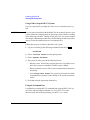
Video Connection
Video Connection
Model 744 Board Computers with on-board graphics circuit have the display
RAM and can be configured for several types of monitors. Graphic monitors
connect to the 15-pin video connector. Figure 4-5 shows the video connector, and Table 4-4 shows the video connector pinouts.
Figure 4-5
Video Connector
Table 4-4
Video Connector Pins and Signals
Pin
Number
Signal
Pin
Number
Signal
1
DDC
9
GND
2
GND
10
HSYNC
3
RED
11
+5V
4
GND
12
GND
5
GREEN
13
SSYNC
6
GND
14
GNC
7
BLUE
15
VSYNC
8
GND
4-11
Cables
Keyboard and Mouse Connections
Keyboard and Mouse Connections
There are two PS/2 style serial ports: one PS/2 keyboard port and one PS/2
mouse port. In the Boot Console Handler’s hardware menu, they are listed as
PS/0 and PS/1. Figure 4-6 shows the PS/2 connector. Also refer to
Figure 4-1; the two ports on the right, labeled Mouse and Keyboard.
Figure 4-6
PS/2 Connector
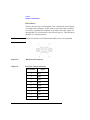
Table 4-5 shows the PS/2 connector pinouts.
Table 4-5
PS/2 Connector Pinouts
Pin Number
4-12
Signal
1
Data
2
Not used
3
GND
4
+5
5
Clock
6
Not used
Cables
Network Connection
Network Connection
LAN circuits use the Ethernet/IEEE 802.3 standard interface. Only the
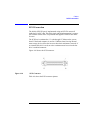
Attachment Unit Interface (AUI) version is used; no BNC connector is provided for ThinLAN. Figure 4-7 shows the AUI LAN connector. Also refer to
Figure 4-1.
The AUI connector enables connections to an external MAU.
Figure 4-7
AUI LAN Connector
Table 4-6 shows the AUI LAN connector pinouts.
4-13
Cables
Network Connection
Table 4-6
AUI LAN Connector Pinouts
Pin Number
4-14
Signal
1
GND
2
CI-A
3
DO-A
4
DI-S (GND)
5
DI-A
6
GND
7
CO-A (NC)
8
CO-S (NC)
9
CI-B
10
DO-B
11
DO-S (GND)
12
DI-B
13
+12V
14
GND
15
CO-B (NC)
Cables
Printer Connections
Printer Connections
Preparing for HP-UX Installation
You may have to do some configuration for appropriate data interchange
with a new printer. This section gives you general guidance for these tasks.
You can use SAM (System Administration Manager) procedures to make
your printer installation easier. SAM can determine the status of any of your
connected devices and performs the necessary software installation of the
printer for you.
If you don’t want to use SAM to install the printer, or if SAM is not on your
system, you can use HP-UX commands directly to accomplish the same
tasks. For information on using manual system administration procedures,
see HP-UX System Administration Tasks.
Configuring HP-UX for a Printer
You will need to supply certain items of information needed to identify the
printer you are installing. It will help to have this reference information
available during the software installation process. In the following checklist,
fill in the items relevant to your printer:
Printer Interface
•
Parallel:_____________________________________________
•
Serial (RS-232C) (Port A):______________________________
•
Serial (RS-232C) (Port B): ______________________________
•
Printer Name (a name the system uses to identify the printer. It can be
any name.):________________________________________
•
Printer Model Number (located on a label on the back of the printer):_________________________________________________
4-15
Cables
Printer Connections
Printer Cables
For connection to the board computer high-density parallel port, depending
on what printer you have and whether you select parallel or serial data
exchange, you will need to select from the following:
•
HP A4300A (HP Parallel): high-density 25-pin to standard 25-pin “F”
•
HP A4301A (Serial): 9-pin high density to standard 9-pin “M”
Other standard cables may be required, depending on the selected printer.
Installation Procedure
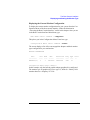
Follow these steps to install your printer:
1 Log in as root. If you do not know how, or do not have permission to log
in as root, ask your system administrator for help.
2 Run SAM by typing the following command:
/usr/sbin/sam Enter
If you need help using SAM, press the F1 key to obtain context-sensitive
information for the object at the location of the cursor.
Use the arrow keys and Tab to move the highlighted areas around the
screen. Press Enter to “choose” an item when illuminated (such as OK).
3 At the SAM opening screen, choose the following:
Printers and Plotters
4 Choose Printers/Plotters from the next screen.
The system displays a message if there are no printers connected to your
system. Make sure you have a printer connected. Choose OK or press
Enter.
5 From the Actions menu (on the menu bar at the top of the screen),
choose the following:
Add Local Printer/Plotter
4-16
Cables
Printer Connections
6 Choose an appropriate selection on the sub-menu giving options for Parallel, Serial, HP-IB, and so on.
A screen provides you with the information on available parallel or serial
interfaces.
7 If you chose Add Serial (RS-232C) Printer/Plotter, more
than one serial interface could be listed. The serial interfaces are listed in
ascending order. The lowest-numbered serial interface corresponds to the
lowest-numbered serial connector on your system. Choose the one to
which your printer is connected.
8 Choose OK.
A display opens for Add Local Printer/Plotter.
9 Choose the box labeled Printer Name and enter your printer name for
the new printer (see “Printer Interface,” earlier in this chapter).
10 Choose Printer/Model Interface.
11 Use the arrow keys to scroll down the next screen. Find the Model Name
of your printer. Choose OK or press Enter when your printer is highlighted.
12 In the Add Local Printer/Plotter display, select and choose the
box labeled:
Make this the system default printer
13 Choose OK.
14 If the print spooler was not previously running, a screen appears with the
question: Do you want to start the print spooler now?
Choose Yes or press Enter.
15 The system displays a confirmation screen asking if your printer is turned
on, connected to your system, and online. Check your printer to ensure
that it is ready, and press Enter.
16 The system displays the message Task completed. Press Enter.
17 Exit the task and press the Exit SAM function key.
4-17
Cables
Printer Connections
18 Enter the following to exit root and return to user status:
exit Enter
Refer to System Administration Tasks for additional SAM information.
Testing the Printer Installation
If you made your printer the default system printer, type the following commands to test it:
cd Enter
lp .profile Enter
If your printer (called printername) is not listed as the default system printer,
enter the following command to test it:
lp -dprintername .profile Enter
The file named .profile should print out on your new printer.
NOTE:
For information on printer-related problems, see Chapter 6 of this book.
HP Parallel
The parallel port is compatible with Centronics® standards, plus some additional features found in HP Series 700 workstations. It supports a bi-directional register model interface in addition to printer-only DMA. Series 700
Scanjet interfaces are not supported.
A high-density micro D-sub connector is used for the HP Parallel interface.
An HP A4300A conversion cable is required to convert to a standard PC
compatible 25-pin female D-sub cable.
Figure 4-8 shows the HP parallel connector. Also refer to Figure 4-1.
4-18
Cables
Printer Connections
Figure 4-8
HP Parallel Connector
Table 4-7 shows the connector pinouts for the HP parallel connector.
Table 4-7
HP Parallel Connector Pinouts
Pin
Number
Signal
Pin
Number
1
NSTROBE
10
NACK
19
GND
2
Data 0
11
BUSY
20
GND
3
Data 1
12
PE
21
GND
4
Data 2
13
SLCT
22
GND
5
Data 3
14
NAFD
23
GND
6
Data 4
15
NERROR
24
GND
7
Data 5
16
NINIT
25
GND
8
Data 6
17
NSCT IN
9
Data 7
18
GND
Signal
Pin
Number
Signal
4-19
Cables
Printer Connections
RS-232 Port A
There are two PS/2 type serial interfaces - Port A and Port B. The serial ports
use a high-density connector. An HP A4301A conversion cable is required
to convert to a standard PC-compatible 9-pin male D-sub cable. Figure 4-9
shows the RS-232 serial connector. Also refer to Figure 4-1. Table 4-8 shows
the RS-232-C connector pinouts.
NOTE:
The RS-232 Port B is not functional until VME services are operational.
Figure 4-9
RS-232 Serial Connector
Table 4-8
RS-232-C Connector Pinouts
Pin Number
4-20
Signal
1
DCD
2
RXD
3
TXD
4
DTR
5
GND
6
DSR
7
RTS
8
CTS
9
RI
Cables
SCSI Connection
SCSI Connection
The built-in SE SCSI port is implemented using an NCR710 macrocell
inside the I/O ASIC chip. This 8-bit single-ended implementation is compatible with the current Series 700 products and supports 5 MB/sec data transfer rates.
The SCSI bus is terminated to 3.3 volts through 127 Ohms on the system
board. If the board computer is used in a VMEbus chassis having internal
mass storage devices, those devices must have their terminators removed. If
an external disk drive is used, an active terminator must be used on the last
drive’s uncabled connector.
Figure 4-10 shows the SCSI connector.
Figure 4-10
SCSI Connector
Table 4-9 shows the SCSI connector pinouts.
4-21
Cables
SCSI Connection
Table 4-9
SCSI Connector Pinouts
Pin
Number
4-22
Signal
Pin
Number
Signal
Pin
Number
Signal
1
GND
21
GND
41
ATN
2
GND
22
GND
42
GND
3
GND
23
GND
43
BSY
4
GND
24
GND
44
ACK
5
GND
25
GND
45
RST
6
GND
26
DATA 0
46
MSG
7
GND
27
DATA 1
47
SEL
8
GND
28
DATA 2
48
CD
9
GND
29
DATA 3
49
REQ
10
GND
30
DATA 4
50
IO
11
GND
31
DATA 5
12
GND
32
DATA 6
13
NC
33
DATA 7
14
GND
34
Data Parity
15
GND
35
GND
16
GND
36
GND
17
GND
37
GND
18
GND
38
+5
19
GND
39
GND
20
GND
40
GND
5
Powering On and Off
5-1
Powering On and Off
This chapter discusses how to turn on and turn off the system.
The instructions in this chapter assume you are using the HP-UX or HP-RT
operating system.
The major sections within this chapter are:
5-2
•
Turning On the System
•
Turning Off the System
Powering On and Off
Turning On the System
Turning On the System
To turn on the system, perform the following, with all peripheral devices
turned off:
1 Turn on the power to your display. The power indicator LED on the display unit shows that it is turned on, even if the screen remains dark. Make
sure of the following:
•
For systems using a graphics display, there must be a keyboard connected (the monitor will not initialize if no keyboard is present).
•
The appropriate LAN connection has been made to the Model 744.
•
If you use a remote graphical display host connected via LAN, make
sure the remote system is configured to host the board computer. Normally, you will use a character terminal connected to the RS-232C
(Port A) on the board computer.
2 Check the SCSI connections and power on any peripheral devices.
3 Turn on the VMEbus chassis. Your Model 744 system turns on with the
VMEbus chassis that it is plugged into.
NOTE:
If your Model 744 does not have on-board or supplementary graphics, the
default console display is available through the RS-232C (Port A).
If there is a problem arising from the console path having been changed, you
can boot your Model 744 to display on any console device. See “Configuring
the Console Path and Display Format” and “Using the Emergency Interactive
Console Search” in Appendix A.
The green LED (on the right) on the panel blinks slowly until the OS is
booted; then remains on. The red LED (on the left) will be on when power
is activated and before HP-UX boots. After VME services is booted, the
red light is off.
5-3
Powering On and Off
Turning On the System
4 The system displays a sequence of boot messages. The Model 744 boots
from the host system unless it has its own external disk or another LANconfigured system from which to boot. See Appendix A for configuring
an automatic boot selection. Otherwise, allow the boot to continue.
NOTE:
The remaining steps apply for HP-UX. If you are using HP-RT, refer to HPRT System Administration Tasks for information on booting an HP-RT
system.
5 During the boot process, a new system displays messages prompting you
for the host name, IP number, and time zone. If you have this information,
enter it as requested. Otherwise, press Enter.
You can also enter or update this information later by typing the following
after you log in as root:
set_parms initial Enter
The information is as follows:
a The time zone where your system is located.
b The host name for your system: any alphanumeric, single-word name
with eight or fewer characters.
c The network address number, also called an IP address, for your system. This consists of four address fields separated by periods: for example, 255.32.3.10. You may need to consult with your system
administrator for this information. Or, if your host name and IP address have already been assigned, you can find out the host name, after
boot, by entering uname -a. If you know your host name, you can determine your IP address by entering nslookup host_name, at the system prompt.
6 The system prompts you to set a root password at this time.
The system completes the boot sequence and displays the following
prompt:
Console login:
5-4
Powering On and Off
Turning Off the System
Turning Off the System
This section provides step-by-step instructions for powering down your
Model 744.
CAUTION:
If you have a local disk attached to the Model 744, do not turn off power to
the system without first shutting down the operating system software
according to the following procedure. Turning off the power for your system
without first doing the shutdown procedure may result in damage to data on
your disk. Always execute the shut-down process to completion first.
1 Exit all processes currently running.
2 Enter the following command to bring the system to a halted state
reboot -h
This gives a zero-length “grace period” before the system goes down to
the halted state.
3 After completing several shutdown procedures, the system eventually displays one of the following messages:
HP-UX Message
Halted, you may now cycle power.
HP-RT Message
**** HP-RT OS is down ****
Halting (in tight loop) -- OK To Hit Reset Button
4 At this time the system no longer responds to keyboard input and you may
turn off the power. Turning the system back on initiates the boot sequence.
If you want to shutdown and reboot automatically, instead of the above procedure, simply enter the reboot command with no options.
See reboot(1M)) for various other options.
5-5
Powering On and Off
Turning Off the System
Using SAM to Stop the HP-UX System
If you are using SAM, you might also want to use it to shut down your system.
CAUTION:
If you are using a local disk with the Model 744, do not turn off power to your
system without first shutting down the operating system software according
to the following procedure. Turning off the power for your system without
first doing the shutdown procedure may result in damage to data on your disk.
Always execute the shutdown process to completion first.
Follow these steps to use SAM to shut down your system.
1 Log in as root and type the following command, followed by Enter:
/usr/bin/sam
2 Choose Routine Tasks from the opening menu.
3 Choose System Shutdown.
4 The system provides you with the following choices:
•
Halt the system. All currently executing processes except those essential to the system are terminated. Then the system is halted.
•
Reboot (restart) the system. The system is shut down and rebooted automatically.
•
Go to Single User State. The system is put in single-user mode
for administrative purposes such as backup or file system consistency
checks.
5 Exit SAM using the appropriate function key.
Using the Command Line
For guidance on entering HP-UX commands and using the HP-UX file system, tools, and networking commands, see Using HP-UX. For more
advanced work with shell programming, see Shells: User’s Guide.
5-6
6
Solving Problems
6-1
Solving Problems
This chapter provides information on troubleshooting various problems.
The instructions in this chapter assume you are using the HP-UX operating
system.
The major sections within this chapter are:
6-2
•
Interpreting the LEDs
•
Managing a Boot Failure
•
Printer Problems
Solving Problems
Interpreting the LEDs
Interpreting the LEDs
The Model 744 provides two LEDs, located to the left and right of the reset
switch, as shown in Figure 6-1. The red LED is labeled SYSFAIL and the
green LED is labeled POWER.
Reset Switch
Red LED
Figure 6-1
Green LED
Model 744 LED Location
6-3
Solving Problems
Interpreting the LEDs
Table 6-1 provides information on the red and green LEDs.
Table 6-1
6-4
LED Indicators
SYSFAIL
(Red)
POWER
(Green)
Off
Off
On
2Hz Flash
On
Off
On
Meaning
No Power
Possible Solution
Check for board seating in
chassis.
Normal Power-on/selftest
Memory Failure
Troubleshoot for failed RAM
card or problem with the
RAM connection.
1 Flash/sec.
CPU (board) Failure
Replace the system board.
On
4 Flash/sec.
No console identified
Check the console search
path and keyboard connections. If no problem is found,
replace the system board.
On
On
OS is booted with
VME services failure
Check the Operating System
VME services. Check that
VME services is configured
in the kernel.
Off
On
OS is booted with
VME services OK
Solving Problems
Managing a Boot Failure
Managing a Boot Failure
The boot program is located in the firmware of your Model 744. You can
configure the behavior of the boot process by interacting with the Boot Console Handler (BCH). See Appendix A for procedures dealing with the boot
console handler.
Problems during the first stage of the boot process are rare. If you have indications that the boot process has failed, check the following items with the
power to the system off:
•
No power to the host system. Check the local circuit breakers and the
power connections to your VMEbus chassis.
•
The Model 744 is not fully plugged into its VME slot.
•
The LAN MAU connector is loose.
•
The SCSI cable is not properly connected.
•
Proper connection of interface/option cards
After checking these items wait five or ten seconds and power on the system.
If the problem recurs, record the following information and report it to your
HP service representative:
Symptoms
Status of the LED indicators
Messages that appear on your system console
6-5
Solving Problems
Printer Problems
Printer Problems
If you experience problems in printing, check the following:
6-6
•
The power cord for the printer is plugged in.
•
The printer is turned on.
•
The printer selection switches are set for online.
•
Paper is loaded into the printer (and it is not jammed).
•
The correct interface has been set up.
•
The printer cable is connected to the correct interface port on your
printer.
•
The cable is connected to the correct port on your system.
A
The Boot Console Interface
This chapter describes the interface to the Boot Console Handler (BCH).
A-1
The Boot Console Interface
Boot Console User Interface Features
Boot Console User Interface Features
There are times when you want to interact directly with the hardware of your
single board computer before it boots the operating system. Your 744 system provides a menu-driven boot console interface that allows you to perform special tasks, display information, and set certain system parameters,
even if the operating system is unavailable.
Here are some of the things you can do:
A-2
•
Boot your workstation
•
Search for bootable media
•
Reset your workstation
•
Display and set boot paths
•
Display and set your monitor type
•
Display memory configuration information
•
Display the status of the EISA slots
•
Set Auto Boot and Auto Search
•
Set Fastboot
•
Display LAN information
•
Display system information
•
Display PIM information
•
Display and Set VME backplane networking
•
Display and Set VME backplane boot ROM
•
Display and Set the VME Chassis Codes Mode flag
•
Restore the factory default VME configuration in the EEPROM
The Boot Console Interface
Boot Console User Interface Features
The boot console menus follow, showing the various tasks you can perform
and the information available.
The shortened version of all commands is indicated by the uppercase letters.
Help is available for all menus and commands by using either help, he, or ?
and the menu or command you want help on.
Main Menu
------ Main Menu -----------------------------------------Command
Description
-------
-----------
BOot [PRI|ALT|<path>]
Boot from specified path
PAth [PRI|ALT|CON|KEY][<path>]
Display or modify a path
SEArch [DIsplay|IPL] [<path>]
Search for boot devices
COnfiguration [<command>]
Access Configuration menu/commands
INformation [<command>]
Access Information menu/commands
SERvice [<command>]
Access Service menu/commands
VME
Access VME menu/commands
[<command>]
DIsplay
Redisplay the current menu
HElp [<menu>|<command>]
Display help for menu or command
RESET
Restart the system
-----Main Menu: Enter command >
A-3
The Boot Console Interface
Boot Console User Interface Features
Configuration Menu
------ Configuration Menu -------------------------------------------Command
Description
-------
-----------
AUto [BOot|SEArch] [ON|OFF]
Display or set specified auto flag
BootID [<proc>] [<boot ID>]
Display or modify processor boot ID
BootINfo
Display boot-related information
BootTimer [0 - 200]
Seconds allowed for boot attempt
DEfault
Set the system to predefined values
FastBoot [ON|OFF]
Display or set boot tests execution
MOnitor [LIST|<path> <type>]
Change the current monitor type
PAth [PRI|ALT|CON|KEY] [<path>]
Display or modify a path
SEArch [DIsplay|IPL] [<path>]
Search for boot devices
SECure [ON|OFF]
Set/show security mode
TIme [c:y:m:d:h:m:[s]
Read or set real time clock in GMT
BOot [PRI|ALT|<path>]
Boot from specified path
DIsplay
Redisplay the current menu
HElp [<menu>|<command>]
Display help for menu or command
RESET
Restart the system
MAin
Return to Main Menu
-----Configuration Menu: Enter command >
A-4
The Boot Console Interface
Boot Console User Interface Features
Information Menu
------ Information Menu ---------------------------------------------Command
Description
-----------
-----------
ALL
Display all system information
BootINfo
Display boot-related information
CAche
Display cache information
ChipRevisions
Display revisions of VLSI and firmware
COprocessor
Display coprocessor information
FwrVersion
Display firmware version
IO
Dispay I/O interface information
LanAddress
Display built-in system LAN address
MEmory
Display memory information
PRocessor
Display processor information
WArnings
Display selftest warning messages
BOot [PRI|ALT|<path>]
Boot from specified path
DIsplay
Redisplay the current menu
HElp [<menu>|<command>
Display help for menu or command
RESET
Restart the system
MAin
Return to Main Menu
-----Information Menu: Enter command >
Service Menu
------ Service Menu ------------------------------------Command
Description
-------
-----------
ChassisCodes [<proc>]
Display chassis codes
CLEARPIM
Clear (zero) the contents of PIM
EepromRead [<addr>] {<len>]
Read EEPROM locations
MemRead <addr> [<len>] [a]
Read memory locations
PIM [<proc> [HPMC|TOC]]
Display PIM information
BOot [PRI|ALT|<path>]
Boot from specified path
DIsplay
Redisplay the current menu
HElp [<menu>|<command>]
Display help for menu or command
RESET
Restart the system
MAin
Return to Main Menu
-----Service Menu: Enter command >
A-5
The Boot Console Interface
Boot Console User Interface Features
VME Menu
------- VME Menu -----------------------------------------------------------Command
-----------
BPNconfig <cpu> <anchor> <am>
Show or set VME BPN parameters
BPRconfig <addr> <am>
Show or set VME BPR parameters
ModeFlags [CC [ON|OFF]]
Show or set state of mode flags
NV_SECTIONS DEfault ALL
Restore NV sections factory defaults
BOot [PRI|ALT|<path>]
Boot from specified path
DIsplay
Redisplay the current menu
HElp [<menu>|<command>]
Display help for menu or command
RESET
Restart the system
MAin
Return to Main menu
------VME Menu: Enter command >
A-6
Description
-------
The Boot Console Interface
Accessing the Boot Console Interface
Accessing the Boot Console Interface
To access the boot console interface, follow these steps:
NOTE:
This procedure should be done by a system administrator with root user
privileges.
1 Close any files and applications on your workstation.
2 In a terminal window, enter the following command:
reboot -h
3 When the system has completely shut down, power off the system then
power it back on.
If Autoboot is turned off, the boot sequence automatically stops at the boot
console Main Menu.
If Autoboot is turned on, you will see the following messages:
Processor is starting Autoboot process. To discontinue,
press any key within 10 seconds.
If Autoboot and Autosearch are both turned on, you will see the following messages:
Processor is booting from first available device.To
discontinue, press any key within 10 seconds.
NOTE:
If you are using a power-saving monitor, you will have less than 10 seconds
from the time this message appears to press a key. Power saving monitors
usually indicate the presence of a live video sync signal through the power
LED on the monitor. When the LED is on, press ESC .
A-7
The Boot Console Interface
Accessing the Boot Console Interface
4 Press a key. You will then see the following message:
Boot terminated
The Main Menu of the boot console appears.
------ Main Menu -----------------------------------------Command
-----------
BOot [PRI|ALT|<path>]
Boot from specified path
PAth [PRI|ALT|CON|KEY][<path>]
Display or modify a path
SEArch [DIsplay|IPL] [<path>]
Search for boot devices
COnfiguration [<command>]
Access Configuration menu/commands
INformation [<command>]
Access Information menu/commands
SERvice [<command>]
Access Service menu/commands
VME
Access VME menu/commands
[<command>]
DIsplay
Redisplay the current menu
HElp [<menu>|<command>]
Display help for menu or command
RESET
Restart the system
-----Main Menu: Enter command >
A-8
Description
-------
The Boot Console Interface
Booting Your Workstation
Booting Your Workstation
Usually, you start your workstation by turning it on and waiting for the operating system to boot automatically. However, you may not always want the
usual sequence to occur.
For example, you may want to start your workstation from an operating system that is stored on a device that is different from your usual boot device. If
your normal operating system kernel or the disk on which it resides becomes
damaged or unusable, you may wish to boot from a different disk or perhaps
another type of device, such as a DDS-format tape drive.
Here are some situations and examples:
•
If you know which device you want to boot from, and you know that it
contains a bootable operating system, follow the directions in “Accessing
the Boot Console Interface” earlier in this chapter, and then type the following at the prompt:
Main Menu: Enter command >
boot device
where device is the hardware path to the device, specified in Mnemonic Style
Notation. When prompted whether or not to interact with the ISL enter n for no.
For example, if you wish to boot an operating system that is stored on a DDSformat tape in a drive that is located at ‘‘sescsi.1.0’’, follow the directions in
“Accessing the Boot Console Interface” earlier in this chapter, and then type the
following command at the prompt:
Main Menu: Enter command > boot sescsi.1.0
Interact with ISL (Y,N,Q)> n
The operating system on the specified device is used to start your workstation.
A-9
The Boot Console Interface
Booting Your Workstation
•
The Initial System Loader (ISL) is the program that actually controls the
loading of the operating system. By interacting with ISL, you can choose
to load an alternate version of the HP-UX operating system. If you wish
to interact with the ISL before booting your workstation, follow the directions in “Accessing the Boot Console Interface” earlier in this chapter, and
then type the following at the prompt:
Main Menu: Enter command > boot device
You are prompted:
Interact with ISL (Y,N,Q)>
Answering quit (q) aborts the boot and returns you to the boot console
handler.
Answering no (n) continues the boot sequence with the device specified
from the main menu prompt.
Answering yes (y) causes the ISL to be loaded from the specified device.
After a short time, the following prompt appears on your screen:
ISL>
For example, if the usual kernel (/stand/vmunix) on your root disk (fwscsi.6.0)
has become corrupted, and you wish to boot your workstation from the backup
kernel (/stand/vmunix.prev), type the following at the ISL> prompt:
ISL> hpux /stand/vmunix.prev
To quit out of the ISL without booting, you must power cycle to board computer.
•
A-10
If you do not know which media in your file systems have bootable operating systems, you can find them with the search IPL command. See the
section “Searching for Bootable Media”.
The Boot Console Interface
Searching for Bootable Media
Searching for Bootable Media
To list devices that contain bootable media, follow the directions in “Accessing the Boot Console Interface” earlier in this chapter, and then type the following at the prompt:
Main Menu: Enter command > search ipl
The search command searches all buses. The search may turn up more
devices than there are lines on your display. If you are using a text terminal,
you may control the progress of the search from your terminal’s keyboard by
using the following commands:
•
•
•
To hold the display temporarily, press Ctrl S
To continue the display, press Ctrl Q
To halt the search, press any other key
These flow-control commands do not work with a bitmapped display, but
such a display can show more than forty lines of text, so you are unlikely to
need them.
To search for devices of just one type that actually contain bootable media,
follow the directions in “Accessing the Boot Console Interface” earlier in
this chapter, and then type the following at the prompt:
Main Menu: Enter command >
search ipl device_type
Where device_type is one of the following:
sescsi is the built-in single-ended SCSI bus
lan is all connections to the built-in LAN
gscn is an optional fast, wide SCSI interface in slot number n
bpn is VME backplane networking
bpr is VME backplane ROM boot
ata is a PCMCIA card (supported by HP-RT operating system only)
pcin is an optional PCI card in slot n
pmcn is an optional PMC card in site n
A-11
The Boot Console Interface
Restoring the Factory Default Configuration
Restoring the Factory Default Configuration
To restore the factory default values in the EEPROM, follow the directions
in “Accessing the Boot Console Interface” earlier in this chapter, and then
type the following at the prompt to access the Configuration Menu:
Main Menu: Enter command > co
When the Configuration Menu appears, type the following at the prompt:
Configuration Menu: Enter command > default
The process takes less than 30 seconds and messages similar to the following are displayed:
Initializing...
TEST 30CD
INIT 30CD
Configuration Menu: Enter command >
The factory default EEPROM settings are now restored. This process does
not affect the VME configuration in the EEPROM.
The defaults are as follows:
OS_ID:
Fast Size:
Primary Path:
Alternate Path:
Console Path:
Keyboard Path:
Autoboot:
Autosearch
Autostart
A-12
HP-UX
0xF (all memory is tested)
sescsi.6.0
sescsi.5.0
GRAPHICS(n) where n is the lowest numbered
device installed. If no graphics devices are
installed this is set to SERIAL_1.
PS2
OFF
OFF
ON
The Boot Console Interface
Displaying and Setting Paths
Displaying and Setting Paths
A path is the hardware address of a device that is attached to the I/O system
of your workstation. The path command sets the system paths shown in
Table A-1.
The path command sets and displays the hardware address of a specified
device attached to the I/O bus of your workstation.
Table A-1
Path Type
System Paths
Device
primary or pri
Your workstation’s default boot device (usually the root
disk)
alternate or alt
Your workstation’s alternate boot device (usually a DDSformat tape device)
console or con
Your workstation’s primary display device
keyboard or
key
Your workstation’s primary ASCII input device
To display the current settings for the system paths, type the following at the
prompt:
Main Menu: Enter command > path
To obtain a full listing of currently supported boot device “mnemonic”
paths, use the following command:
Main Menu: Enter command > pa prim ?
To obtain a full listing of currently supported console “mnemonic” paths,
use the following command:
Main Menu: Enter command > pa con ?
A-13
The Boot Console Interface
Displaying and Setting Paths
The paths are displayed in Mnemonic Style Notation, as shown in
Table A-2.
Table A-2
Mnemonic Style Notation
I/O Type
A-14
Specification Format
Built-in SCSI
sescsi.scsi_address.logical_unit_number
Optional
gscn.scsi_address.logical_unit_number
Built-in LAN
lan.server_address.init_retries.io_retries
VME Backplane
Networking
bpn.server_address.init_retries.io_retries
VME Backplane
ROM Boot
bpr.vme_addr.VME_addr_mod
PCMCIA
ata
PCI Slot
pcin
PMC Slot
pmcn
On-board Graphics
graphics(0)
Optional Graphics 1
graphics(1)
Optional Graphics 2
graphics(2)
PS/2 Keyboard
ps2
HIL Keyboard
hil
RS232(A)
serial_1.baudrate.wordlength.parity
RS232(B)
serial_2.baudrate.wordlength.parity
The Boot Console Interface
Displaying and Setting Paths
To display the current setting for a particular system path, follow the directions in “Accessing the Boot Console Interface” earlier in this chapter, and
then type the following at the prompt:
Main Menu: Enter command > path path_type
where path_type is one of the path types listed in Table A-1.
For example, to get the path to the primary boot device, follow the directions
in “Accessing the Boot Console Interface” earlier in this chapter, and then
type the following at the prompt:
Main Menu: Enter command > path primary
To set a system path to a new value, follow the directions in “Accessing the
Boot Console Interface” earlier in this chapter, and then type the following
at the prompt:
Main Menu: Enter command > path path_type path
where path_type is one of the path types listed in Table A-1 and path is the
specification of the path in Mnemonic Style Notation (as described in Table
A-2). For example, to set the primary boot path to a SCSI disk with an ID of
6.0, follow the directions in “Accessing the Boot Console Interface” earlier
in this chapter, and then type the following at the prompt:
Main Menu: Enter command > path pri sescsi.6.0
A-15
The Boot Console Interface
Displaying and Setting the Monitor Type
Displaying and Setting the Monitor Type
Your system ships from the factory preset to use a monitor with a specific
resolution and frequency. If you replace your workstation’s monitor with a
different type of monitor, you must reconfigure your workstation to support
the new monitor.
The Monitor Command
The monitor command lets you change your workstation’s graphics configuration. This command is available in the Configuration Menu of the boot
console interface.
To display the current graphics and console information, enter the following
command:
Configuration Menu: Enter command > monitor
The correct usage for setting the graphics configuration is:
Configuration Menu: Enter command > monitor graphics_path type
where valid graphics_path parameters are:
graphics(0) - The on-board 8-plane graphics adapter.
graphics(1) - Graphics adapter installed in option slot 1.
graphics(2) - Graphics adapter installed in option slot 2.
and type is the numerical monitor type as shown with the monitor list command.
NOTE:
A-16
Standalone boards are shipped from the factory configured to monitor type 0
to force a monitor type polling loop on initial boot.
The Boot Console Interface
Displaying and Setting the Monitor Type
Displaying the Current Monitor Configuration
To display the current monitor configuration for your system from the Configuration Menu of the boot console interface, follow the directions in
“Accessing the Boot Console Interface” earlier in this chapter. Once you are
in the Boot Console Interface Main Menu, type:
Main Menu: Enter command > configuration
This places you in the Configuration Menu. From here type:
Configuration Menu: Enter command > monitor
The screen displays a list of the current graphics adapters and their monitor
types configured for your workstation.
MONITOR INFORMATION
Path
Slot
Head
HPA
Resolution
Freq
Type
----------
----
----
------
----------
----
----
GRAPHICS(0)
0
1
f8000000
1280x1024
72Hz
12
Class
--
Configuration Menu: Enter command >
In this example, only the built-in graphic adapter graphics(0) is configured.
The monitor type for graphics(0) is set to type 12, which is a 1280 by 1024
monitor that uses a frequency of 72 Hz.
A-17
The Boot Console Interface
Displaying and Setting the Monitor Type
Setting the Monitor Type
You can set the monitor type for a graphics adapter from the configuration
menu by entering the following:
Configuration Menu: Enter command > monitor graphics(n) tt
Where n is the number of the graphics adapter and tt is the monitor type.
To display a list of supported monitors, enter the following command;
Configuration Menu: Enter command > monitor list
A list of valid monitor types similar to the following is displayed;
MONITOR INFORMATION
Path
Slot Head Type
----
---- ---- ---- ---------
Size
Freq
Class
----
-----
GRAPHICS(0)
0
1
1
1280x1024
75Hz
VESA
*GRAPHICS(0)
0
1
2
1280x1024
75Hz
VESA, Double buffered
GRAPHICS(0)
0
1
3
1280x1024
75Hz
VESA, Greyscale
*GRAPHICS(0)
0
1
4
1280x1024
75Hz
VESA, Double Buffered,Greyscale
GRAPHICS(0)
0
1
5
1024x768
75Hz
VESA
GRAPHICS(0)
0
1
6
800x600
75Hz
VESA
GRAPHICS(0)
0
1
7
640x480
75Hz
VESA
*GRAPHICS(0)
*GRAPHICS(0)
*GRAPHICS(0)
*GRAPHICS(0)
0
1
8
1600x1200
75Hz
VESA
0
1
9
1600x1200
75Hz
VESA,Greyscale
0
1
10
1200x1600
75Hz
VESA
0
1
11
1200x1600
75Hz
VESA,Greyscale
GRAPHICS(0)
0
1
12
1280x1024
72Hz
*GRAPHICS(0)
0
1
13
1280x1024
72Hz
GRAPHICS(0)
0
1
14
640x480
60Hz
GRAPHICS(0)
0
1
15
--------user defined-------
Double buffered
Configuration Menu: Enter command >
* These monitor types are not supported on the Model 744 on-board graphics.
A-18
The Boot Console Interface
Displaying and Setting the Monitor Type
To set the monitor type for graphics(0) to monitor type 2 you would enter
the following;
Configuration Menu: Enter command > monitor graphics(0) 2
This will take effect on the next reboot.
MONITOR INFORMATION
Slot
Head
Resolution
Freq
Type
Class
-----------
Path
----
----
--------
HPA
----------
----
----
-----
GRAPHICS(0)
0
1
f8000000
1280x1024
72Hz
2
The boot console displays a message that tells you that your new monitor
selection will take effect the next time you reboot your system.
The boot console also displays the new monitor information.
Trying to change the monitor type to a number not listed for that graphics
device fails and gives you the following warning message:
Value of monitor type n out of range (n - nn)
A-19
The Boot Console Interface
Displaying and Setting the Monitor Type
Setting the Monitor Type at Power On
If you replace your workstation’s monitor with a different monitor type, and
do not set the workstation’s graphics parameters by using the monitor command before doing so, you need to perform the following steps at power on:
If your keyboard connects to the PS/2 connector on your system, wait 2 seconds after the Num Lock light flashes near the end of the boot sequence,
then press Tab to initiate the automatic monitor selection process.
If you have a keyboard that connects to the HIL connector on your system,
press Tab every three seconds during the boot sequence to initiate the automatic monitor selection process.
The system cycles through all of the available monitor types one at a time.
When you can see a message similar to the following clearly and legibly,
select that monitor type by pressing Enter.
MONITOR INFORMATION
Path
----------GRAPHICS(0)
Slot
Head
Type
Size
Freq
Class
----
----
----
----------
----
-----
nnnnxnnnn
nnHz
0
1
n
Press [RETURN] to select this monitor type (type n of n types).
NOTE:
If you are using a power saving monitor, the power LED will light when the
monitor senses a valid video synch signal.
The system queries you to confirm your selection. Press Y to save this monitor type.
If you press any key other than Y, the following message is displayed:
Monitor type not saved.
At this point, the new monitor type is active, but not saved. Because you
didn’t save the monitor type, the next time you reboot the system, the original monitor type will be used.
Next, the following message is displayed:
To select a new Graphics Monitor Type press the <TAB> key now,
otherwise EXIT by entering any other key (or will time out in
15 seconds)...
To restart the monitor selection process, press TAB.
A-20
The Boot Console Interface
Displaying and Setting the Monitor Type
Using the Emergency Interactive Console Search
If the system console is set to a device that is not installed in the system, you
can use the emergency interactive console search to set the console to one of
the terminal devices that is currently connected.
Use the following procedure to set the console with the emergency interactive console search:
1 Make sure that the monitor(s) and/or terminal(s) are powered on.
2 Hold the Model 744 board computer’s reset/abort switch in its Abort position, then turn on power to the VMEbus chassis.
3 A message similar to the following is displayed on each monitor connected to a graphics device recognized by the system:
GRAPHICS(s) MONITOR INFORMATION
Slot
Model
Type
Resolution
Freq
Class
----
-----------------
----
----------
----
-----
1280x1024
75Hz
0
INTERNAL_EG_1280
12
The following keyboard(s) are available:
PS2
HIL
Press the <n> key to select GRAPHICS(s) as the CONSOLE or
press the <Tab> key to select the next monitor type.
Where n is a single-digit number or a keyboard key.
When the message is displayed clear and undistorted on the monitor for your
console device, enter the number or key that corresponds to the display device
that you are selecting.
NOTE:
The message is displayed for sixty seconds before proceeding to the next monitor
resolution.
If you are using a power saving monitor, the power LED will light when the monitor
senses a valid video synch signal.
If this message is not displayed on your monitor, review the procedures in Chapter 1
and Chapter 2 to make sure that you correctly installed the option board.
A-21
The Boot Console Interface
Displaying and Setting the Monitor Type
If no keyboards are found the following message is displayed:
WARNING: No keyboard(s) found. Turn off system
power, check keyboard connection(s) and
repeat interactive console search.
To advance all graphics adapter monitors to the next resolution, press the <Tab>
key one time and wait five seconds for all monitor types to change. Do not hold
down the <Tab> key or press it multiple times as this will cause the monitor
types to advance for each press of the <Tab> key.
4 When the following message is displayed, press the <Esc> key to confirm
selection of the device as the console:
Press the <Esc> key to confirm selection of GRAPHICS(s) as
the CONSOLE.
This selection will timeout in 10 seconds if not confirmed.
NOTE:
The message is displayed for only ten seconds before console search is
resumed. Press <Esc> as soon as possible after the message is displayed.
The following message is displayed on the selected display:
GRAPHICS(s) MONITOR INFORMATION
Slot
Model
Type
Resolution
Freq
Class
----
-----------------
----
----------
----
-----
1280x1024
75Hz
0
INTERNAL_EG_1280
12
Selected CONSOLE path is: GRAPHICS(s)
Selected KEYBOARD path is: PS2
A-22
The Boot Console Interface
Displaying the Current Memory Configuration
Displaying the Current Memory Configuration
The memory command shows the memory configuration table.
To display the current memory configuration for your system, from the
Information Menu of the boot console interface, follow the directions in
“Accessing the Boot Console Interface” earlier in this chapter. Once you are
in the Boot Console Interface Main Menu, type:
Main Menu: Enter command > information
This places you in the Information Menu. From here type:
Information Menu: Enter command > memory
The screen displays status and configuration information for the memory
modules installed in your workstation.
Memory Information Example
If a memory card failure is detected during power-on selftest, the following
message is displayed on the console (after completing all selftests) and the
autoboot/autosearch process is automatically stopped:
WARNING: One or more memory banks were not configured due
to a SIMM size mismatch or a SIMM failure. For
more details, use the MEMORY command in the
INFORMATION menu.
NOTE:
The above condition occurs only after the testing and successful
configuration of at least one memory card.
A-23
The Boot Console Interface
Displaying the Current Memory Configuration
The following listing is a sample memory configuration table when memory
modules are properly installed and configured:
MEMORY INFORMATION
MEMORY STATUS TABLE
Slot
Size
Status
---------------0
64MB
Configured
1
32MB
Configured
2
64MB
Configured
--------TOTAL
160MB
If the power-on selftest detects a defective or damaged memory card, using
the memory command (from the Information Menu prompt) displays the
following information:
WARNING: One or more memory banks were not configured due
to errors in the following SIMM(s).
Physical Slot
------------3
Error Type
----------SIMM hardware error
Memory Card Stack
+-------------------------+
Slot 3 |
Failed
|
+-------------------------+
+-------------------------+
Slot 2 |
64MB OK
|
+-------------------------+
+-------------------------+
Slot 1 |
32MB OK
|
+-------------------------+
+-------------------------+
Slot 0 |
64MB OK
|
+-------------------------+
==========================================================
Side view of Model 9000/744/165L Single Board Computer PCB.
SUGGESTION: If possible, turn off the computer and check to
see if the memory card(s) are seated properly.
Memory
HVERSION
--------------0x0740
A-24
SVERSION
--------------0x0900
The Boot Console Interface
Displaying the Status of the System I/O
Displaying the Status of the System I/O
The IO command is available from the information menu. It lets you identify all built-in I/O devices and optional I/O devices installed in the option
slots.
To use the IO command from the Information Menu of the boot console
interface, type:
Information Menu: Enter command > IO
Information about the built-in and optional I/O devices is displayed as
shown in the following example:
I/O MODULE INFORMATION
Path
-----------8
8
GRAPHICS(1)
GSC2
8/16
8/16/0
8/16/1
SERIAL_1
SESCSI
LAN
PS2
8/16/8
8/20
HIL
EISA
GRAPHICS(0)
8/28
VME
BPN
SERIAL_2
BPR
62
63
Decimal
------8
8
8/0
8/8
8/16
8/16/0
8/16/1
8/16/4
8/16/5
8/16/6
8/16/7
8/16/8
8/20
8/20/1
8/20/5
8/24
8/28
8/28/0
8/28/1
8/28/2
8/28/3
62
63
Type
----------------Bus Converter
Bus Converter
HPA208LC1024
A DMA I/O
Bus Adapter
Parallel
Audio
RS232
SE SCSI
LAN
Keyboard
Mouse
Bus Adapter
HIL
Bus Adapter
INTERNAL_EG_1280
Bus Adapter
Bus Adapter
BPN
RS232
BPR
Native Processor
Proc Dep Memory
Location HVER
-------------built-in 5040
built-in 5050
GSC slot1 0080
GSC slot2 0141
built-in 04b0
built-in 04b0
built-in 04b4
built-in 04b0
built-in 04b0
built-in 04b0
built-in 04b0
built-in 04b0
EISA
0110
EISA
0110
EISA
0110
built-in 04b0
built-in 04a0
built-in 04a0
built-in 04a0
built-in 04a0
built-in 04a0
built-in 50f0
built-in 0740
SVER
---0000
0000
8500
8980
8100
7400
7b00
8c00
8200
8a00
8400
8400
8e00
7300
9000
8500
9300
7800
8800
8c00
8f00
0481
0900
IODC
Vers
---0x00
0x00
0x01
0x96
0x00
0x00
0x00
0x01
0x96
0x02
0x00
0x00
0x00
0x00
0x00
0x01
0x00
0x00
0x00
0x01
0x00
0x00
0x00
IODC
Dep
---0x00
0x00
0x00
0x00
0x00
0x00
0x00
0x00
0x00
0x00
0x00
0x00
0x00
0x00
0x00
0x00
0x00
0x00
0x01
0x00
0x01
0x00
0x00
EISA Cards
Path
Type
EISA ID
------------20/5/1
100VG AnyLAN adapter cardHWP1990
20/5/2
Unknown EISA card or empty slot
20/5/3
Smart 16/4 Ringnode cardMDG0002
20/5/4
PSI card
HWP1870
20/5/5
Unknown EISA card or empty slot
20/5/6
Unknown EISA card or empty slot
20/5/7
Unknown EISA card or empty slot
20/5/8
Unknown EISA card or empty slot
PCI Cards
Slot
Path
-----------------------------VME Cards
Path
Type
-------
Bus
---
Class
--------------
VME ID
-------
Information Menu: Enter command >
A-25
The Boot Console Interface
Setting the Auto Boot and Auto Search and Auto Start Flags
Setting the Auto Boot and Auto Search and Auto Start
Flags
The auto boot, auto search, and auto start flags are variables stored in
your workstation’s nonvolatile memory. (Nonvolatile memory retains its
contents even after power is turned off.) If you reset these flags to a new
value, the change takes effect the next time you reboot the workstation.
The auto boot variable boots the operating system whenever your workstation is turned on.
To examine the state of auto boot and auto search, type the following at the
prompt:
Configuration Menu: Enter command > auto
If auto boot is set to on, your workstation automatically attempts to boot the
operating system when turned on. If auto boot is set to off, your workstation
enters the boot administration mode of the boot console user interface.
The state of auto search determines how your workstation seeks a boot
device during autoboot. If auto search is set to on, your workstation will
search for other boot devices if the primary boot device is not available. If
auto search is off, your workstation will default to the boot administration
mode if it can’t see the primary boot device.
To change the state of auto boot or auto search, enter either of the following commands at the prompt:
Configuration Menu: Enter command > auto boot state
Configuration Menu: Enter command > auto search state
where state is on or off.
A-26
The Boot Console Interface
Setting the Auto Boot and Auto Search and Auto Start Flags
Autosearch searches for devices in the following order:
Primary Boot Path
Alternate Boot Path
FW SCSI in GSC Slot 1
FW SCSI in GSC Slot 2
Built-in Single-Ended SCSI Devices
Built-in LAN bootp servers
NOTE:
The following paths are not searched unless they are referenced by the
primary or alternate boot paths:
bpn
bpr
ata
EISA and VME cards are not searched.
A-27
The Boot Console Interface
Displaying and Setting the Security Mode
Displaying and Setting the Security Mode
The SECure flag is a variable stored in non-volatile memory. (Non-volatile
memory retains its contents even after power is turned off.) If you reset this
flag to a new value, the change takes effect the next time you reboot the
board computer.
When the SECure flag is set to on, autoboot and autosearch are enabled
and cannot be stopped. The system boots from the default boot paths regardless of user intervention.
To display the current setting for the SECure flag, enter the following command:
Configuration Menu: Enter command > secure
To set the SECure flag on or off, enter one of the following:
Configuration Menu: Enter command > secure on
Configuration Menu: Enter command > secure off
A-28
The Boot Console Interface
Displaying and Setting the Fastboot Mode
Displaying and Setting the Fastboot Mode
When fastboot is enabled (set to on), your workstation does a quick check
of the memory and skips I/O interface testing during its power-on self tests.
This enables your workstation to complete its boot process more quickly.
The default factory setting is for fastboot to be disabled (off).
The fastboot mode allows your workstation to boot quickly by performing a
less extensive check of the system’s memory.
When fastboot is disabled (set to off), more extensive memory testing and
I/O interface testing is performed during the selftests, causing the boot process to take longer.
If you are experiencing difficulty in booting your workstation, set fastboot
to off and reboot the system. The more extensive testing may reveal the error
condition.
To display the status of fastboot, type the following at the prompt:
Configuration Menu: Enter command > fastboot
To disable fastboot, type the following at the prompt:
Configuration Menu: Enter command > fastboot off
To enable fastboot, type the following at the prompt:
Configuration Menu: Enter command > fastboot on
CAUTION:
If a graphics adapter is installed in the system, it must be selected as the
console device. If additional graphics adapters are installed, Fastboot mode
cannot be used.
A-29
The Boot Console Interface
Displaying the LAN Station Address
Displaying the LAN Station Address
It is sometimes necessary to supply a LAN station address of your workstation to other users. For example, if your workstation is to become a member
of a cluster, the cluster administrator needs to know your LAN station
address in order to add your workstation to the cluster.
A LAN station address of your workstation is the label that uniquely identifies the LAN connection for your workstation at the link level (the hardware
level).
To display your workstation’s LAN station addresses, type the following at
the prompt:
Information Menu: Enter command > lanaddress
The LAN station address is displayed as a twelve-digit number in hexadecimal notation, similar to the following:
LAN Station Addresses:
0060b0-789abc
The address is for the system’s built-in LAN.
A-30
The Boot Console Interface
Displaying System Information
Displaying System Information
The all command allows you to display the system’s processor revision and
speed, cache size, memory size, flag settings, and the boot and console
paths. To display system information from the Information Menu, type the
following at the prompt:
Information Menu: Enter command > all
This information is paged to allow you to view it as necessary.
A-31
The Boot Console Interface
Displaying PIM Information
Displaying PIM Information
The pim command allows you to display the most recent PIM information
for the specified fault type. To display PIM information for a specific fault,
type the following at the Service Menu prompt:
Service Menu: Enter command > pim processor_number
You can use pim in the following ways:
pim - Gives all fault types
pim 0 - Gives HPMC information on the processor
pim 0 fault_type -Provides fault type information on the processor. Where
fault_type is HPMC, LPMC, or TOC
A-32
The Boot Console Interface
Displaying and Setting VME Backplane Networking Configuration
Displaying and Setting VME Backplane Networking
Configuration
On the VME menu, BPNconfig is used to display or set the VME backplane
networking parameters stored in non-volatile memory.
To display the current VME backplane networking parameters enter the following at the VME menu prompt:
VME Menu: Enter command > bpn
The information is displayed similar to the following example:
Current BPN Configuration Parameters:
CPU Number: 0
Anchor:
0x00200000
AM:
0x3d
Use the following syntax to set the VME backplane networking parameters:
BPNconfig - Show backplane networking configuration
BPNconfig cpu - Set CPU number only
BPNconfig cpu anchor - Set CPU number and VME anchor address
BPNconfig cpu anchor am - Set CPU number, VME anchor address
and VME address modifier code
For example,
bpnconfig 1 0x200000 0x3d
sets the backplane networking resources for CPU number 1, with the VME
anchor address set to 0x200000 and the VME address modifier code is set to
0x3d.
A-33
The Boot Console Interface
Displaying and Setting VME Backplane ROM Boot Configuration
Displaying and Setting VME Backplane ROM Boot
Configuration
On the VME menu, BPRconfig is used to display or set the VME backplane
ROM boot parameters stored in non-volatile memory.
To display the current VME backplane ROM boot parameters enter the following at the VME menu prompt:
VME Menu: Enter command > bpr
The information is displayed similar to the following example:
Current BPR Configuration Parameters:
Address:
0x00000000
AM:
0x3d
VME Menu: Enter command >
Use the following syntax to set the VME backplane ROM boot parameters:
BPRconfig - Show backplane ROM boot configuration
BPRconfig addr - Set VME address only
BPRconfig addr am - Set VME address and VME address modifier code
For example,
bprconfig 0x0 0x3d
sets the backplane ROM boot VME address to 0x0 and the VME address
modifier code to 0x3d.
A-34
The Boot Console Interface
Displaying and Setting the VME Chassis Codes Mode Flag
Displaying and Setting the VME Chassis Codes Mode
Flag
On the VME menu, ModeFlags is used to display or set flags which enable
or disable the display of diagnostic chassis codes on SERIAL_1.
To display the current setting of the mode flag enter the following command:
VME Menu: Enter command > mf
The information is displayed similar to the following example
Diagnostic Chassis Codes to SERIAL_1:
ENABLED
VME Menu: Enter command >
Use the following syntax to set the VME chassis code mode flag:
ModeFlags - Shows current state of all mode flags
ModeFlags cc on - Enables the display of diagnostic chassis codes
on SERIAL_1
ModeFlags cc off - Disables the display of diagnostic chassis codes
on SERIAL_1
A-35
The Boot Console Interface
Restoring the Factory Default VME EEPROM Configuration
Restoring the Factory Default VME EEPROM
Configuration
The NV_SECTIONS command restores the non-volatile sections area of the
system EEPROM to the default factory settings.
To restore the factory default settings, enter the following command:
VME Menu: Enter command >nv_sections de all
CAUTION:
All VME system configuration data maintained in this area of the EEPROM is
restored to the factory default setting. All user data contained in this area of the
EEPROM is ERASED.
CAUTION:
Do not reset the system or interrupt the power during the update process. The update
requires approximately 6 minutes to complete.
A-36
Index
A
accessories, 1-7
audio, 1-16
auto boot, A-26
changing state, A-26
auto search, A-26
changing state, A-26
auto start, A-26
B
backplane networking, A-33
boot console
features, A-2
menus, A-3
configuration, A-4
information, A-5
main, A-3
service, A-5
VME, A-6
bootable media
searching for, A-11
C
cables, 1-8
connecting, 4-1
audio, 4-8
keyboard, 4-12
monitor, 4-4
mouse, 4-12
network, 4-13
printer, 4-15
SCSI, 4-21
terminal, 4-4
video, 4-11
conversion, 4-5
printer, 4-16
commands
all, A-31
auto, A-26
boot, A-9
eisa, A-25
fastboot, A-29
lanaddress, A-30
memory, A-23
path, A-13
pim, A-32
reset, A-12
search, A-11
D
documentation conventions, Preface7
E
EISA slots
displaying status, A-25
electrostatic discharge, Preface-4
emissions
regulations, Preface-2
environmental requirements, 1-9
F
fastboot, A-29
disabling, A-29
displaying status, A-29
enabling, A-29
features, 1-3
Federal Communications Commission (FCC), Preface-2
G
GSC, 1-3
I
information
online, 1-13
system, 1-12
installation
accessories, 2-1
expansion kit, 2-8
graphics boards, 2-13
GSC mezzanine cards, 2-11
memory, 2-5
PMC bridge, 2-13
PMC expansion, 2-13
cables, 4-1
configuring VME card cage, 3-3
HP-RT, 1-15
HP-UX, 1-15
keyboard, 4-12
keyboard and mouse, 3-7
Model 744, 3-8
non-HP VME cage, 3-10
monitor, 4-4
mouse, 4-12
network cable, 4-13
notes, 1-6
overview, 1-6
printer, 4-15
SCSI connections, 4-21
terminal, 4-4
K
keyboard, 1-8
L
LAN station address, A-30
displaying, A-30
LED codes, 6-3
M
manuals
related, Preface-5
system information, 1-12
maximum temperatures, 1-9
memory
displaying configuration, A-23
failure, A-23
nonvolatile, A-26
monitor
displaying type, A-16, A-17
setting type, A-18
setting type at power on, A-20
mouse, 1-8
N
nonvolatile memory, A-26
Index-1
Index
O
operating system, 1-11
HP-RT, 1-11
HP-UX, 1-11
overview, 1-11
P
path, A-13
displaying, A-13
setting, A-15
PCI, 1-3
PIM information
displaying, A-32
PMC, 1-3
PMC bridge adapter, 2-13
PMC expansion adapter, 2-13
power
worksheet, 3-5, 3-6
power off, 5-1
power on, 5-1
power requirements, 3-3
precautions
electrostatic discharge, Preface-4
printer
configuring, 4-15
connecting, 4-15
product description, 1-3
R
regulations
emissions, Preface-2
related manuals, Preface-5
release documents, Preface-4
removal
Model 744, 3-12
revision history, Preface-6
S
solving problems, 6-1
boot failure, 6-5
LED codes, 6-3
printer, 6-6
supported products, 1-7
Index-2
system information
displaying, A-31
T
troubleshooting, 6-1
boot failure, 6-5
LED codes, 6-3
printer, 6-6
W
workstation
booting, A-9
resetting to predefined parameters,
A-12