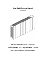
1
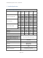
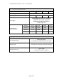
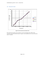
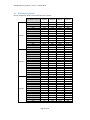
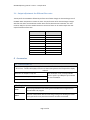
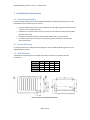
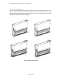
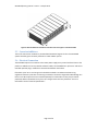
SmartRad Planning Manual
Issue 1 – 15 April 2010
Dimplex SmartRad Fan Convector
Models SRX80, SRX120, SRX140 & SRX180
Applies to models with White Glass, Black Glass and Metal facias
SmartRad planning manual – Issue 1 – 15 April 2010
Contents
1
Introduction to the SmartRad ......................................................................................................... 4
2
Benefits of the SmartRad ................................................................................................................ 4
3
4
5
6
2.1.1
Smaller dimensions ......................................................................................................... 4
2.1.2
Low flow temperature .................................................................................................... 4
2.1.3
Lower Water content ...................................................................................................... 5
2.1.4
Rapid heat up .................................................................................................................. 5
2.1.5
Fast Reacting ................................................................................................................... 5
2.1.6
Less stratification ............................................................................................................ 5
2.1.7
Low surface temperature................................................................................................ 6
SmartRad Specification ................................................................................................................... 7
3.1
Technical and performance data ............................................................................................ 7
3.2
Electrical specification ............................................................................................................ 8
3.3
Hydraulic connection .............................................................................................................. 8
3.4
Pressure Losses ....................................................................................................................... 9
3.5
SRX Outputs (Watts) ............................................................................................................. 10
3.6
Output adjustment for different flow rates .......................................................................... 11
Accessories .................................................................................................................................... 11
4.1
Filter set SRX FS ..................................................................................................................... 11
4.2
Plug in timers ........................................................................................................................ 11
Installation Considerations ........................................................................................................... 12
5.1
SmartRad positioning ............................................................................................................ 12
5.2
System Balancing .................................................................................................................. 12
5.3
Wall Mounting ...................................................................................................................... 12
5.4
Water Connection ................................................................................................................. 13
5.5
Corrosion inhibitors .............................................................................................................. 14
5.6
Electrical Connection ............................................................................................................ 14
Typical applications ....................................................................................................................... 15
6.1
Whole house ......................................................................................................................... 15
6.2
SmartRads mixed with Radiators .......................................................................................... 15
6.3
SmartRads mixed with under floor heating .......................................................................... 15
6.4
Ground Source heat pumps .................................................................................................. 15
Page 2 of 19
SmartRad planning manual – Issue 1 – 15 April 2010
Controls and Control strategies ............................................................................................................ 16
7
6.5
Mixed SmartRad and Radiator circuits ................................................................................. 16
6.6
Boiler interlock ...................................................................................................................... 16
6.7
SmartRad controls................................................................................................................. 16
6.8
Central system control .......................................................................................................... 16
6.9
Individual SmartRad control Plug in controllers ................................................................... 17
6.10
Spring and autumn operation ............................................................................................... 17
6.11
Summer operation ................................................................................................................ 17
6.12
Pump optimisation ................................................................................................................ 17
Designing the system for Maximum Efficiency ............................................................................. 18
7.1
Choosing a Mean Water Temperature (MWT) ..................................................................... 18
7.1.1
Suggested MWT ............................................................................................................ 18
7.1.2
Air off temperatures ..................................................................................................... 18
7.2
Weather compensation ........................................................................................................ 18
Page 3 of 19
SmartRad planning manual – Issue 1 – 15 April 2010
1 Introduction to the SmartRad
The SmartRad is a stylish and modern alternative that out performs traditional radiators. At the
heart of the SmartRad is a heat exchanger with a large surface area, which allows effective transfer
of heat into the room even at low flow temperatures. To increase the amount of heat output there is
an energy efficient fan which forces air over the heat exchanger. By being able to give a decent heat
output at low flow temperatures, the SmartRad makes it even more viable to install heat pumps
when refurbishing a property.
2 Benefits of the SmartRad
Thanks to the heat exchanger and fan the increased heat output means that the SmartRad takes up
less wall space compared to a standard radiator when operating under the same conditions. The
following examples demonstrate the benefits of the SmartRad over traditional radiators.
2.1.1 Smaller dimensions
A Radiator with dimensions of 530x911mm would need to have a Mean Water Temperature (MWT)
of 73⁰C to give an output of 1kW whilst the SmartRad would only need a MWT of 40⁰C to give the
same 1kW output. This means the system can be run at significantly lower flow temperature which
will give significant savings in system efficiency.
2.1.2 Low flow temperature
As shown in Figure 1 a standard radiator operating at a flow temperature of 40⁰C would need to
measure 530x3128mm whilst
Figure 2 shows that the SmartRad would only need to be 530x911mm – that is over 3½ times
smaller. Therefore, by using the SmartRad it becomes practical to fit the product into a room and
still operate at lower flow temperatures.
Page 4 of 19
SmartRad planning manual – Issue 1 – 15 April 2010
.
Figure 1: Radiator sizes based upon a “Double convection” design with an output of 1537W
Figure 2: SmartRad size based upon fan speed 2 setting with an output of 1537W.
2.1.3 Lower Water content
The SmartRad contains only a fraction of the water compared to a traditional radiator. A traditional
1kW radiator operating at a flow temperature of 73⁰C could contain up to 35 litres of water, where
as the SRX180 gives a 1kW output when operating at only 40⁰C but contains only 0.6 litres – that is
over 50 times less water.
2.1.4 Rapid heat up
The low water content makes the SmartRad highly reactive, when the heating demand increases the
heat pump only has to heat a small volume of water to 40⁰C. However with a radiator the boiler
would have to heat the 35 Litres of water to 73⁰C.
2.1.5 Fast Reacting
The low water content is also beneficial if the heating demand is suddenly decreased if for example
there is suddenly a solar gain. With a radiator the large thermal mass will stubbornly keep emitting
heat even though the room is up to temperature, however with a SmartRad the fan will modulate its
speed down and the low thermal mass will quickly cool down meaning that the room is not over
heated.
2.1.6 Less stratification
With a traditional radiator, the high water flow temperature means that the air off temperatures is
high causing a ‘chimney’ effect as the hot air rushes to the ceiling but leaving the floor area cold. The
air in the region around the thermostat is at the correct temperature but the average room
temperature is in fact higher. A lot of heat is lost into the ceiling and though the upper part of the
walls.
Page 5 of 19
SmartRad planning manual – Issue 1 – 15 April 2010
With the SmartRad the lower water flow temperatures and increased mixing of the air by the fan
mean that there is less temperature stratification, meaning that the average room temperature is in
fact lower, meaning there is less heat loss to the ceiling and upper walls. The lower heat loss
translates into lower heating bills and a more comfortable climate for the end user.
2.1.7 Low surface temperature
Due to the heat exchanger being installed inside the cover it is possible to pass high temperature
water though the SmartRad without the casing getting above 43⁰C. This means that the product
could replace a standard high temperature radiator in places such as Nurseries and Care homes.
Please note that full testing and approvals have not been competed yet.
Page 6 of 19
SmartRad planning manual – Issue 1 – 15 April 2010
3 SmartRad Specification
3.1
Technical and performance data
Fan
Speed
SRX080
SRX120
SRX140
SRX180
3
25-27
43-47
56-60
50-53
2
19-20
29-32
36-40
33-35
1
16-17
20-22
24-26
23-24
3
228
345
410
540
2
125
190
225
300
1
60
100
120
160
3
36
36
36
36
2
29
29
29
29
1
26
26
26
26
Water Content (l)
0.31
0.43
0.48
0.60
Length (mm)
503
670
740
911
Height (mm)
530
530
530
530
Depth (mm)
145
145
145
145
Fan Power Consumption (W)
3
Air Flow rate (m /h)
Sound Level @ 1m dB(A)
Installed weight (kg) – White metal front
Installed weight (kg) – White glass front
Not currently available at time of print.
Installed weight (kg) – Black glass front
Installation
wall mounted
Water protection of housing
IP X0
Front Panel
White metal front
White Glass front
Black Glass front
Rear Panel
Metal
Approvals and certification
CE declaration of conformity
Conforms to EN 55014, EN 61000-3-2, EN 61000-3-3
Page 7 of 19
SmartRad planning manual – Issue 1 – 15 April 2010
3.2 Electrical specification
Dimplex product name
SRX080
SRX120
Nominal voltage (V)
SRX140
SRX180
∼ 230-240
Fuse rating (A)
3A
Power Cable
4 core cable each with cross section of
0.75mm2, (live, neutral, earth and
black wire for “pilot wire function”)
usable length 1m,
Electrical Power
Consumption (W)
3A
3A
3A
Speed 3
25-27
43-47
56-60
50-53
Speed 2
19-20
29-32
36-40
33-35
Speed 1
16-17
20-22
24-26
23-24
PCB only
1
1
1
1
3.3 Hydraulic connection
Flow and return pipes
15mm copper pipes
50mm between middle of flow and return pipes
Air bleed valve
Air bleed valve on the top of the heat exchanger
Typical flow rate (l/h)
Typical 150l/h
(can range from 100 l/h to 450 l/h )
Page 8 of 19
SmartRad planning manual – Issue 1 – 15 April 2010
3.4 Pressure Losses
18
16
Pressure Drop kPa
14
12
10
SRX080
SRX120
8
SRX140
6
SRX180
4
2
0
0
100
200
300
400
500
Flow Rate l/h
Figure 3: Pressure losses and various flow rates
Note: these pressure drops are only indicative. Each of the SmartRads have a different heat
exchanger and therefore a different pressure. Figure 3 will be updated with the correct information
when it is available.
Page 9 of 19
SmartRad planning manual – Issue 1 – 15 April 2010
3.5 SRX Outputs (Watts)
Inlet air temperature of 20⁰C and a water flow rate of 150 l/h
Speed 3
Speed 2
Speed 1
Mean Water Temp ⁰C
SRX080
SRX120
SRX140
SRX180
30
33
35
38
40
43
45
48
50
53
55
58
60
63
65
30
33
35
38
40
43
45
48
50
53
55
58
60
63
65
30
33
35
38
40
43
45
48
50
53
55
58
60
63
65
485
613
741
869
996
1124
1252
1380
1508
1635
1763
1891
2019
2147
2274
314
394
474
554
634
714
794
874
954
1034
1114
1194
1274
1354
1434
163
204
245
286
327
368
409
450
491
532
573
614
655
696
737
730
923
1115
1308
1500
1693
1885
2078
2270
2463
2655
2848
3041
3233
3426
401
521
640
759
878
997
1117
1236
1355
1474
1593
1713
1832
1951
2070
271
339
408
476
545
613
682
750
819
887
956
1024
1093
1161
1230
854
1079
1304
1530
1755
1980
2206
2431
2656
2882
3107
3332
3558
3783
4008
551
693
835
977
1119
1261
1403
1545
1687
1829
1971
2113
2255
2397
2539
323
405
487
569
650
732
814
896
977
1059
1141
1223
1305
1386
1468
1088
1375
1662
1949
2236
2523
2810
3097
3384
3671
3958
4245
4532
4819
5106
718
903
1088
1273
1457
1642
1827
2012
2197
2382
2567
2752
2936
3121
3306
423
530
637
745
852
959
1067
1174
1281
1389
1496
1603
1711
1818
1925
Page 10 of 19
SmartRad planning manual – Issue 1 – 15 April 2010
3.6 Output adjustment for different flow rates
The output of the SmartRad is affected by the flow rate of water though the heat exchanger even if
the Mean water temperature remains the same. The performance of the heat exchanger changes
with flow rate due to increased heat transfer when the flow becomes more turbulent. For most
instances 150l/h is the most suitable however a conversion factor can be used to adjust the heat
output for different flow rates.
Flow Rate l/h
Adjustment Factor
50
100
150
200
250
300
350
400
450
0.87
0.93
1.00
1.04
1.06
1.09
1.10
1.10
1.10
4 Accessories
4.1 Filter set SRX FS
Filter set can be clipped to the air inlet grill of the SmartRad. The filter is easily cuttable in order to fit
all four sizes. The filter will slightly restrict the air flow meaning that the heat output will be slightly
reduced.
Dimensions of unit (W x H x D) mm
Factor to calculate the power output reduction
This information is not currently available.
Please speak to your Dimplex representative
for more information.
Factor to calculate the air flow reduction
4.2 Plug in timers
RX24Ti
24 hour programmable timer allowing each SmartRad to be configured to its
own individual time program
RXRBTi
Electronic runback timer ideal for controlling running costs allowing the heater
to only operate for a set period each time the controller is activated.
Page 11 of 19
SmartRad planning manual – Issue 1 – 15 April 2010
5 Installation Considerations
5.1 SmartRad positioning
In many instances the position of the SmartRad will already be dictated by the design of the room.
Consideration must however be given to avoid:
•
•
•
•
Fixing the product near curtains or other materials that are light weight and could be moved
in the air current created by the fan.
Installation in an environment where dirt, dust or pet hair could be sucked into the product
and block the air flow.
Installation immediately above or below a fixed socket outlet or connection box.
In a location where the risk of water entering the product is possible for example bath
rooms and kitchens.
5.2 System Balancing
It is essential that there is adequate flow through each of the SmartRads. Balancing valves are not
supplied with the product.
5.3 Wall Mounting
The appliance should be securely mounted to the wall to minimise the possibility of noise
transmission.
Model
SRX080
SRX120
SRX140
SRX180
A
503
670
740
911
B
324
492
562
732
C
396
564
634
804
D
386
564
624
794
Figure 4: Product and installation dimensions
Page 12 of 19
SmartRad planning manual – Issue 1 – 15 April 2010
5.4 Water Connection
There are a number of different plumbing options which the installer can adapt depending on the
project as shown in Figure 5. The inlet and outlet pipes on the heat exchanger are plain 15mm pipe.
Note that on the left hand side of the product the pipes pass in front of each other but on the right
hand side pass side by side as shown in Figure 6.
Figure 5: Possible routes for piping
Page 13 of 19
SmartRad planning manual – Issue 1 – 15 April 2010
Figure 6: Note the different orientation of the flow and return pipes on the LHS and RHS.
5.5 Corrosion inhibitors
The use of anticorrosion inhibitors is permitted with SmartRad. A general rule is that SmartRad
system should be given the same protection as a wet radiator system.
5.6 Electrical Connection
The SmartRad requires a connection to the mains power supply via a junction box fixed close to the
product. In addition to the Live, Neutral and Earth cables, the SmartRad has a ‘pilot wire’ and can be
used with optional plug in modules to communicate between the heaters.
If the black ‘pilot’ wire is not being used it should be isolated in accordance with IEE wiring
regulations. When the pilot wire is switching to set back it becomes energised at 240V although at a
low current. Where pilot wires are installed separately from the heater circuitry they should be
protected, double insulated and carry their own integral earth continuity conductor. For more
information see the “Electrical Specification” .
Page 14 of 19
SmartRad planning manual – Issue 1 – 15 April 2010
6 Typical applications
The SmartRad is highly versatile; it can be used in conjunction with radiators or in conjunction with
under floor heating. In all cases it is important to ensure that there is always an adequate flow of hot
water at the correct temperature through the SmartRad throughout the entire heating season. In a
domestic installation is typical to have all the heat emitters sized based upon the same mean water
temperature.
6.1 Whole house
SmartRads are ideal if the installer is aiming to reduce the flow temperature as low as possible, but it
is not practical to install under floor.
6.2 SmartRads mixed with Radiators
It is possible to combine standard radiators and SmartRads in the same installation. This is
particularly common if the radiators in some rooms are too large or the number of radiators in each
of the rooms needs to be reduced for aesthetic reasons. Special care needs to be taken to ensure
that there is the correct flow rate through the radiators and SmartRads.
6.3 SmartRads mixed with under floor heating
Under floor heating typically operates at low flow temperatures to maximise the efficiency of the
heat pump of boiler. In many houses it is not practical to install under floor heating upstairs. If the
installer wanted to install radiators upstairs it would be necessary to increase the flow temperature
in order to get enough heat out of the radiators, this would mean that a second heating circuit
would have to be installed and the temperature mixed down to make it cool enough for the under
floor.
By installing the SmartRads upstairs, there is no need to install a second heating circuit as the
SmartRads can operate at the same temperature as the under floor system. Typical MWT should be
higher than 40⁰C to prevent air off temperature from the SmartRad feeling too cold.
6.4 Ground Source heat pumps
When installing the SmartRad extra care must be given to the running hours and sizing of the ground
source heat pump. If the heat load is larger than expected the ground source heat pump will
attempt to draw more heat from the ground than is available. This situation could occur if the
SmartRad is sized to run on a low fan speed during the design stage but the heat load for the area is
much higher in practice and the SmartRad is actually run on a higher fan speed drawing more heat
from the system than expected.
Page 15 of 19
SmartRad planning manual – Issue 1 – 15 April 2010
Controls and Control strategies
Figure 7: SmartRad controls
6.5 Mixed SmartRad and Radiator circuits
It is permissible to place radiators and SmartRads on the same heating system however the flow
rates and MWT through each product should be considered to ensure that they give the desired
output. I will be necessary to correctly balance the system.
6.6 Boiler interlock
It is a requirement under the building regulations that all boilers should have interlock. i.e. a method
of minimising system operation if there is no heating requirement.
6.7 SmartRad controls
There is a temperature coil installed on the water coil that measures its temperature. The sensor
prevents the fan from running if the MWT is less than 2⁰C warmer than room temperature or if the
water is cooler than 14⁰C. If the water temperature is too low this will be indicated by the power
light flashing. This feature has 3 benefits:
•
•
Prevents the fan from running if there is no heat available from the heating system. This
prevents cold air being blown around the room and also allows the SmartRad to be
“disabled” centrally when there is no flow through the product by turning off the pump.
Prevents the SmartRad from taking more heat from the system if the water temperature is
lower than 14⁰C. This means that an air source heat pump will always have enough energy
to perform a defrost.
6.8 Central system control
The SmartRad is automatically disabled after a short time when there has been no flow through the
product. This is achieved because when the circulating pump is switched off, the flow in the
SmartRad will stop and its temperature starts to drop. The fan will be disabled once the water in the
fan coil has cooled within 2⁰C of room temperature. As soon as the temperature rises above 2⁰C the
fan will be enabled again.
Page 16 of 19
SmartRad planning manual – Issue 1 – 15 April 2010
This means that the entire heating system can be enabled by a central timer clock which controls a
circulating pump. The added advantage of SmartRad over radiators with TRVs is that the thermal
mass of the SmartRad is much lower so therefore less heat is wasted when the system is turned off.
6.9 Individual SmartRad control Plug in controllers
There may be times when it is desirable for some areas of the property to be heated and others not
to be heated. This can be archived by having the central pump running and installing timers on the
SmartRad in areas where no heating is required. With the plug in timers, there is still flow through
the water coil, however, because the fan is not running the heat emitted is very low.
In addition to control system already on the SmartRad controllers extra optional controllers can be
fitted for increased control. This would be an ideal way to minimise running costs if not all parts of
the building are occupied all of the time.
6.10 Spring and autumn operation
When the weather starts improving, there will become times in the day when heating is no longer
required. If weather compensation is enabled on the heat pump this will moderate the flow
temperature to ensure that heating is only supplied when it is needed. During times when heating is
not required for short periods it is best to leave the power on so that the SmartRad can control
things correctly. The advantage of leaving the SmartRads turned on is that the plug in timer
cassettes will retain their settings.
6.11 Summer operation
When the weather has improved sufficiently so that the heat pump or boiler can be switched off or
placed into “Summer mode”, the SmartRads can also be switched off. If the SmartRads are left in
standby they have been designed to use very little power. Leaving them switched on during the
summer has the added benefit that they will not lose their timer settings and no one will need to
remember to turn them on again when the weather gets colder.
6.12 Pump optimisation
For the majority of installations it is not recommended to use Pump Optimisation with the
SmartRads although it may be appropriate in some instances. Some heat pump controllers such as
the WPM 2006/7 give an option to switch off the circulating pumps if the return temperature has
been met for a set period of time. The system then assumes that no heating is required and
therefore can switch off the circuiting pumps. The controller will activate the pumps periodically to
check the system temperature.
Whilst pump optimisation could reduce the running time of the pump, if there is a heating demand
whilst the pump is turned off the SmartRad will be unable to communicate this demand and the
room will not be heated.
Page 17 of 19
SmartRad planning manual – Issue 1 – 15 April 2010
7 Designing the system for Maximum Efficiency
7.1 Choosing a Mean Water Temperature (MWT)
The MWT is the average between the inlet and outlet across the radiator. Feedback from customers
is that a MWT of 40⁰C gives adequate air off temperatures. Some customers have indicated that an
air off temperature with a MWT of 35⁰C is acceptable if they understand the benefits of maximising
heat pump COP.
7.1.1 Suggested MWT
Whilst there is no such thing as a typical installation, the following table suggests suitable flow
temperature although the final choice is up to the installer.
System heater
Typical Mean Water temperature
Water, Air and
Ground source
heat pumps
Ideally low as possible. The lowest recommended
temperature is 35⁰C with weather compensation fully
activated and a design MWT of 40⁰C.
Condensing
boilers
Below 55⁰C so that the flue gasses can condense all year
round. As efficiency is not closely related to temperature it is
best not to enable weather compensation since this will
increase the SmartRad fan run time which has a small
electrical consumption.
Systems with
efficiency not
affected by flow
temperature.
The temperature does not matter so long as it falls within
the product operating limits however care must be given to
transmission losses between the radiators.
Table 1: Summary of suggested MWT temperatures
7.1.2 Air off temperatures
Decreasing the MWT will also decrease the air off temperature. A situation may be reached,
particularly when there is a small heating demand were the air off temperatures are relatively low
but they the room is still being effectively heated. This phenomenon will be more pronounced
because the moving air feels cooler than it actually is. The customer must be informed that the
product operates at low air off temperatures in order to maximise the Heat pump efficiency. If the
customer complains of cool air off temperatures from the product the MWT must be raised which
will have a knock-on effect on the COP.
7.2 Weather compensation
A weather compensation function on a heat pump or boiler decreases the mean temperature of the
heating system as the external temperature increases. Weather compensation will maximise the
Heat Pump COP by ensuring that the MWT is only as high as it needs to be to meet the heating
Page 18 of 19
SmartRad planning manual – Issue 1 – 15 April 2010
demand. Care should be taken when setting the weather compensation curves that the Mean Water
temperature does not fall too low, so that the air off temperatures starts to feel cool.
For a heat pump a lower mean system temperature gives a higher Coefficient of Performance.
However, a lower mean system temperature reduces the output of the SmartRad, meaning that the
fan has to be run on a higher setting. Computer modelling has shown that it is best to use weather
compensation because the increased fan usage is far outweighed by the improvements in COP.
Page 19 of 19