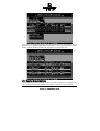
1
&KDSWHU/
*'76(783
,Q'HWDLO
&KDSWHU/*'76(783LQ'HWDLO
/*'76(783LQ'HWDLO
We refer to firmware as the operating system which controls the ICP Controller with all its
functions and capabilities. The firmware exclusively runs on the ICP Controller and is stored
in the Flash-RAM on the ICP Controller PCB. The controlling function is entirely independent of the PCI computer and the host operating system installed (for example UNIX), and
does not "drain" any computing power or time from the PCI computer. According to the
performance requirements needed, the ICP Controllers are available with two firmware variants. The firmware is either already installed on the controller upon delivery, or can be
added as an upgrade: RAIDYNE upgrade.
Standard Firmware (installed on the GDT61xyRP controllers).
In addition to simple controlling functions regarding SCSI hard disks or removable
hard disks, this version allows disk chaining (several drives can be linked in order to
form a single "large" drive), and the configuration of Array Drives of the types data
striping (RAID 0) and disk mirroring or duplexing (RAID 1).
RAIDYNE Firmware (installed on the GDT65xyRP controllers). In addition to disk
chaining, RAID 0 and RAID 1, RAIDYNE allows you to install and control Array
Drives of the types RAID 4 (data striping with dedicated parity drive), RAID 5 (data
striping with distributed parity) and RAID10 (a combination between RAID 0 and 1)
RAIDYNE is the name of the ICP disk-array operating system for the ICP Controllers. Unlike
pure software solutions, RAIDYNE is totally independent of the host operating system, and
can therefore be accessed under MS-DOS, Windows, OS/2, SCO-UNIX, Interactive UNIX,
Novell NetWare, etc.. Special RAID drivers are not needed. The integration of a RAID Array
Drive into the host operating system is carried out with the same drivers used for the integration of a single SCSI hard disk. All ICP Controllers are equipped with a hardware which is
particularly well suited for Array Drives. RAIDYNE uses this hardware with extreme efficiency and therefore allows you to configure Array Drives that do not load the host computer (whereas all software-based RAID solutions more or less reduce the overall
performance of the host computer.).
/7KHIRXU/HYHOVRI+LHUDUFK\LQWKH*'7)LUPZDUH
Both GDT firmware versions (Standard and RAIDYNE) are based on four fundamental levels
of hierarchy. Each level has its "own drives" ( = components). The basic rule is:
To build up a “drive“ on a given level of hierarchy, the “drives“ of the next lower level
of hierarchy are used as components.
/HYHO
Physical Drives = hard disks, removable hard disks, some MO drives are located on the
lowest level. They are the basic components of all "drive constructions" you can set up.
However, before they can be used by the firmware, these hard disks must be "prepared", a
procedure we call initialization. During this initialization each hard disk receives information
which allows an univocal identification even if the SCSI-ID or the controller is changed. For
reasons of data coherency, this information is extremely important for any drive construction consisting of more than one physical drive.
/HYHO
&KDSWHU/*'78VHU
V0DQXDO
On the next higher level are the Logical Drives. Logical Drives are introduced to obtain a
full independence of the physical coordinates of a physical device. This is necessary to easily change the whole ICP Controller and the channels, IDs, without loosing the data and the
information on a specific Array Drive.
/HYHO
On this level of hierarchy, the firmware forms the Array Drives. Depending on the firmware
installed, this can be
Single Disks (one hard disk, some vendors call it JBOD - Just A Bunch Of Drives)
Chaining Sets (concatenation of several hard disks)
RAID 0 Array Drives
RAID 1 Array Drives, RAID 1 Array Drives plus hot fix drive
RAID 4 Array Drives, RAID 4 Array Drives plus hot fix drive
RAID 5 Array Drives, RAID 5 Array Drives plus hot fix drive
RAID 10 Array Drives, RAID 10 Array Drives plus hot fix drive
/HYHO
On the highest level of hierarchy, the firmware forms the Host Drives. In the end, only these
Host Drives can be accessed by the host operating system of the computer. Drives C, D, etc.
under MS-DOS, OS/2, etc. are always referred to as Host Drives by the firmware. The same
applies to NetWare- and UNIX-drives. The firmware automatically transforms each newly
installed Logical Drive and Array Drive into a Host Drive. This Host Drive is then assigned a
Host Drive number which is identical to its Logical Drive or Array Drive number.
The firmware is capable of running several Host Drives of the most various kinds at the
same time. An example for MS-DOS: drive C is a RAID 5 type Host Drive (consisting of 5
SCSI hard disks), drive D is a single hard disk, and drive E is a CD-ROM communicating with
RAIDYNE through corelSCSI and the GDT ASPI manager.
On this level the user may split an existing Array Drive into several Host Drives.
After a capacity expansion of a given Array Drive the added capacity appears as a new Host
Drive on this level. It can be either used as a separate Host Drive, or merged with the first
Host Drive of the Array Drive.
Within GDTSETUP, each level of hierarchy has its own special menu:
/HYHO
/HYHO
/HYHO
/HYHO
Ö
Ö
Ö
Ö
Menu: Configure Physical Device
Menu: Configure Logical Drive
Menu: Configure Array Drive
Menu: Configure Host Drive
Generally, each installation procedure passes through these 4 menus, starting with level 1.
Therefore:
First initialize the Physical Drives.
Then configure the Logical Drives.
Then configure the Array Drives (e.g. Array Drives with RAID 0, 1, 4, 5
and 10).
Finally, configure the Host Drives.
&KDSWHU/*'76(783LQ'HWDLO
/
+
+RVW
W'
'ULYH
H77\SHV
VLLQ
Q5
5$,'<1(
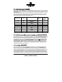
The following summary gives you an overview of all Host Drive types you can create with the
GDT firmware. The ICP Controller can simultaneously control several Host Drives of most
various types.
For instance, MS-DOS drive C could be a Host Drive of the type disk (consisting of a single
SCSI hard disk), MS-DOS drive D is a type RAID 5 Array Drive, MS-DOS drive E is a Host
Drive of the type chain, and MS-DOS drive F is a CD-ROM which communicates with MSDOS through corelSCSI and the GDT ASPI manager.
$YDLODEOHZLWK
)LUPZDUHYDULDQW
7\SHRI+RVW
'ULYH
'HVFULSWLRQRI+RVW'ULYH
,QVWDOODWLRQ
RQ/HYHO
65
'LVN
65
&KDLQ
65
65
5
0LUURU5$,'
5$,'
5$,'
5
5$,'
5
5$,'
DVVLJQPHQW+RVW'ULYHWR
6&6,GHYLFH
&RQFDWHQDWLRQRIVHYHUDO6&6,
GHYLFHV
0LUURULQJRI/RJLFDO'ULYHV
'DWD6WULSLQJ
'DWD6WULSLQJZLWKSDULW\
GULYH
'DWD6WULSLQJZLWKVWULSHG
SDULW\
&RPELQHG5$,'DQG
0LQLPXP
QXPEHURI
6&6,GHYLFHV
S = Standard; R = RAIDYNE Firmware.
/6&6,'HYLFHV:KLFKFDQEH&RQILJXUHG:LWK*'76(783
SCSI devices which can be configured with GDTSETUP are called Direct Access Devices (SCSI
devices such as hard disks or removable hard disks, or other devices behaving like a hard
disk). SCSI devices other than SCSI hard disks or removable hard disks, or devices that do
not behave like them, are called Not Direct Access Devices. They are not configured with
GDTSETUP and cannot form cache or Host Drives. These SCSI devices are either run
through the ASPI interface (Advanced SCSI Programming Interface) (MS-DOS, Windows,
Novell NetWare or OS/2), or they are directly accessed from the operating system (true for
UNIX and Windows NT). For details on how to operate these devices, please refer to the
corresponding chapters of this manual.
//RDGLQJ*'76(783
Any installation or maintenance procedures regarding the ICP Controller are carried out
with the configuration program GDTSETUP. The monitoring program GDTMON allows
continuous monitoring and maintenance of the ICP Controller and the connected Array
Drives. The GDTMON utility also include options to replace a defective drive with a new one
(Hot Plug) and is available for most of the operating systems supported by the ICP Controllers. GDTSETUP allows you to set up single disks or complex Array Drives with simple
and user-friendly installation procedures. Little previous knowledge is needed to be able to
use GDTSETUP efficiently. It is only necessary to understand the hierarchy levels in the ICP
&KDSWHU/*'78VHU
V0DQXDO
Controller firmware (which are the same for both firmware versions: Standard and
RAIDYNE). For the user's convenience the GDTSETUP program is available in two different
variants:
GDTSETUP loaded from the ICP Controller's Flash-RAM after switching on the computer
GDTSETUP loaded from disk under MS-DOS.
The header of the GDTSETUP program indicates with a letter after the version number,
whether GDTSETUP was loaded from disk or from Flash-RAM:
"R" for GDTSETUP loaded from the Flash-RAM after switching on the computer
"D" for GDTSETUP loaded from Disk, i.e., under MS-DOS.
Loading GDTSETUP with <CTRL><G> from the Flash-RAM is very comfortable since no operating system is required to carry out the configuration and setup works.
On the other side, loading GDTSETUP from disk (i.e., under MS-DOS) becomes necessary
for tasks like partitioning or enabling a totally disabled GDT BIOS (which includes
GDTSETUP).
/
66SHFLDO
O.
.H\V
VLLQ
Q*
*'76(783
&XUVRUNH\V n DQG p
Used to select a menu option or command. If a Microsoft-compatible mouse and a mouse
driver are installed, you can also make your choices with the mouse.
(17(5!NH\
Confirms a choice, entry, warning or message in GDTSETUP.
(6&!NH\
Exits the current menu.
63$&(!EDU
Multiple selections, or toggling between a number of preset options.
)XQFWLRQNH\)!
This key has different functions, depending on the menu you are in:
a.
b.
Toggle between Express or Enhanced Setup.
Display drive configuration.
)XQFWLRQNH\)!
To Lock and Unlock removable media.
)XQFWLRQNH\)!
Refresh Information.
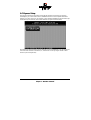
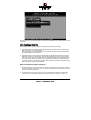
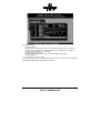
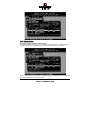
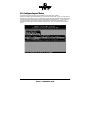
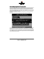
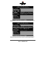
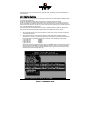
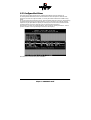
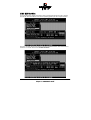
When GDTSETUP is loaded, the main menu appears as shown below:
&KDSWHU/*'76(783LQ'HWDLO
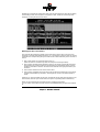
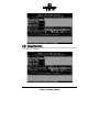
/([SUHVV6HWXS
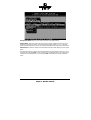
This function allows the easy setup of Array Drives and does not require any previous
knowledge. If you choose this function, GDTSETUP carries out the complete installation
entirely on its own, giving you, for example, a fully operational RAID 5 Array Drive with optimized settings (for instance, with all SCSI features of a given drive activated).
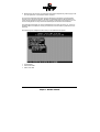
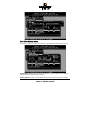
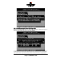
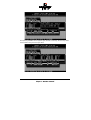
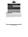
After selecting Configure Host Drives and Create new Host Drive, GDTSETUP scans the system for
ICP Controllers and "free" hard disks (i.e., drives which are not yet logical drives or Host
Drives or part of Array Drives).
&KDSWHU/*'78VHU
V0DQXDO
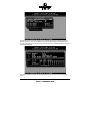
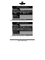
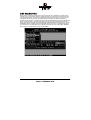
Select with the <Space> bar the hard disks you want to integrate into the new Host Drive.
Depending on the number of selected drives in the Choose Type windows all possible Host
Drive configurations are high-lighted.
&KDSWHU/*'76(783LQ'HWDLO
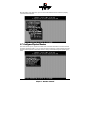
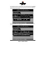
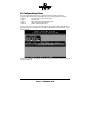
Press <ENTER> . You may select the desired Host Drive type. In our example select RAID5
and press <ENTER> .
That's it!
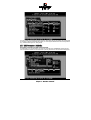
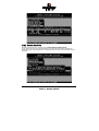
As you can see from the next picture, the RAID5 Array Drive has been fully automatically
configured. It is in the build state.
&KDSWHU/*'78VHU
V0DQXDO
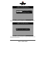
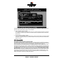
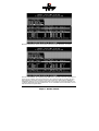
Press several times <F2> to get detailed information on the Array Drive's configuration and
components.
Press several times <ESC> to leave GDTSETUP. A new screen comes up giving you detailed
progress information on the build process.
&KDSWHU/*'76(783LQ'HWDLO
As you can see, the build process for the 4GB Array Drive takes approximately 22 minutes.
If you press <ESC> GDTSETUP warns you that the array is not yet redundant.
Pressing again <ESC> brings up the following screen, telling you the system needs a reboot
to recognize the new Host Drive(s).
&KDSWHU/*'78VHU
V0DQXDO
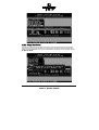
/6HOHFW&RQWUROOHU
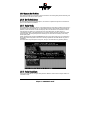
If there are more GDT RP Series controllers in the PCI computer, Select Controller lets you select the controller where you can apply all of the following GDTSETUP choices to. The currently selected controller is displayed on the lower left side of the screen. Below "Position",
the PCI Slot number is displayed. The available features of the ICP Controller depend on the
firmware installed. After a cold boot of the PCI computer, the controllers are recognized and
initialized in the order of this list.
&KDSWHU/*'76(783LQ'HWDLO
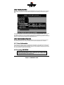
/&RQILJXUH&RQWUROOHU
After pressing <ENTER> and <F2> the Advanced Setup allows to select the Configure Controller
menu option.
Press <ENTER> .
&KDSWHU/*'78VHU
V0DQXDO
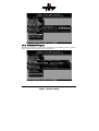
/
&&RQWUROO
OOHHU
U66HWW
WWLLQJV
(To change a setting, move the cursor keys n and p to the field and press <ENTER> .
Note: In order to obtain the full performance of your ICP Controller, it is very important that
the Delayed Write function is 2Q, too. If you find a different setting, we recommend changing
it now.
Function
Cache On (*)
Delayed Write On (*)
BIOS
BIOS Warning Level
Memory Test
SCSI-ID
SCSI Termination
(*)
Possible Settings
On, Off
On, Off
Enabled, Disabled
All messages, Fatal errors
No Test, Standard, Double Scan, Intensive
0,1,2,3,4,5,6,7
On, Off, Auto
Factory Setting
On
On
Enabled
Fatal errors
Standard
7
On
Can also be changed with the GDTMON online utility.
/
))LUPZDUH
H8
8SG
SGD
DWH
The firmware, the BIOS and the GDTSETUP program of the ICP Controller are stored in a
Flash-RAM which is part of the ICP Controller hardware. In contrast to EPROMs, FlashRAMs can be re-programmed many times and without the complicated UV-light erasing
procedure. Thus, both software modules can be easily updated without having to remove
the controller from its PCI slot. Firmware and BIOS are part of the *'7B53): file. The file
has an extension (e.g. GDT_RPFW.009) which indicates the version stepping. The latest version of the this file can be downloaded either from our 24h BBS (+49-(0)-7131-5972-15) or
from our Website http://www.icp-vortex.com. We recommend that you also download the
packed files which contain the latest programs/drivers for the operating system used on
your system. Observe the following order when carrying out the updating procedure:
&KDSWHU/*'76(783LQ'HWDLO
1. Get the latest GDT_RPFW file for the ICP Controller (download it from our BBS, or our
Website, or ask for an upgrade disk if you do not have a modem). The file does NOT
need to be expanded !
2. Format a 3.5" HD disk (1.44MB) and copy the GDT_RPFW file on this disk.
3. After loading GDTSETUP (from Flash-RAM or from disk under MS-DOS) select the desired ICP Controller for the firmware update and press the <F2>-key to enter the Advanced Setup.
4. Select Configure Controller and thereafter Firmware Update. Insert the disk with the firmware
file into drive A. GDTSETUP loaded from the Flash-RAM will display a list of the valid
files found on the disk. If you have loaded GDTSETUP from disk you have to enter the
path "A:", first.
The update process starts as soon as the desired GDT_RPFW file has been selected. Strictly
observe the messages and instructions of GDTSETUP. It is extremely important that the system is not switched off or reset during the update process. It is very likely that this would
cause the ICP Controller to become inoperable.
&KDSWHU/*'78VHU
V0DQXDO
The new versions of the GDT Firmware, the BIOS and GDTSETUP are available after the next
cold-boot.
/
,,QWHOOL
OOLJJHQW
W))DXOW
W%
%XV
The GDT RP Series Controllers support two types of intelligent subsystems:
1. Subsystem which are accessed via the Intelligent Fault Bus (IFB, which is similar to the
DEC™ fault bus). E.g. Storage Works ™.
The IFB is based on an asynchronous bus on the SCSI connector and requires appropriate hard/software in the subsystem.
2. Subsystems which are accessed via SAF-TE (SCSI Accessed Fault Tolerant Enclosures).
SAF-TE is based on the simple idea, that the GDT RP Series controller and the subsystem "talk" to each other via the SCSI bus. The subsystem requires a so-called SEP (SAFTE Enclosure Processor) per channel and an appropriate firmware. The GDT RP Series
controller includes in its firmware modules which provide a full SAF-TE implementation.
(See next pages: Configure Physical Devices).
What are the benefits of intelligent subsystems ?
1. The GDT RP Series controller controls the LEDs. LED indication of the various states of
the hard disk within the Array Drive. E.g., your are shown which drive has failed, or which
drive is currently being rebuilt.
2. Controlled Hot Plug "Auto Hot Plug". No risk of SCSI bus disturbances and electrical
problems. E.g., exchange of a drive is very simple: unplug it and plug in a new one.
&KDSWHU/*'76(783LQ'HWDLO
3. Messaging of the states of the intelligent subsystems temperature, power supply condition, fan speed etc. to the GDT RP Series controller.
Of course the intelligent subsystem must be designed to implement all these features.
The key point is the communication between the subsystem and the GDT RP Series controller. Some subsystems seem to have a lot of LEDs, redundant power supplies, etc., but
are not intelligent at all. They stand there and keep all information for themselves.
The intelligent subsystem can also be integrated into the server enclosure. I.e., there is a
backplane which includes the circuitry and mechanical environment to perform the Auto
Hot Plug.
After selecting the Intelligent Fault Bus menu you are offered three options:
Change Settings
View Channel States
Perform LED Tests
&KDSWHU/*'78VHU
V0DQXDO
The GDT RP Series controllers support in the standard delivery the Intelligent Fault Bus
(IFB) on channel A. The Fault Bus Module is a small PCB which plugs as a daughter board
onto the main PCB of the GDT RP Series controller. Once it is installed, all further channels
are also IFB equipped.
This screen shows you the states of the Fault Bus and the description of the LED blinkcodes.
&KDSWHU/*'76(783LQ'HWDLO
With the Perform LED Tests menu, you can check if the LEDs and blink-codes are properly
controlled and displayed.
/&RQILJXUH3K\VLFDO'HYLFHV
This menu allows you to prepare hard disks and removable hard disks for use with the ICP
Controller (hierarchy level 1). You can scan the SCSI bus again for a given SCSI-ID (this may
become necessary when another SCSI device is being connected during the operating session).
&KDSWHU/*'78VHU
V0DQXDO
This screen tells you:
- the SCSI channel
- which SCSI-ID a drive has (the entry SCSI I/O processor stands for the according SCSI
channel of the ICP Controller. Its default setting is ID 7, as explained in chapter B)
- the state of initialization ("i" = initialized)
- the SCSI names of the drives
- the state, [RW] = Read + Write, [RO] = Read only, [RM] = Removable
- the gross capacity
- if component of a Logical Drive
Use the cursor keys n and p to highlight the drive you wish to initialize. When a SCSI device
is selected with <ENTER>, a new screen is displayed.
&KDSWHU/*'76(783LQ'HWDLO
You may select the high-lighted menu options. The other options are either not appropriate
to the type of device (removable hard disk), or currently blocked because of security reasons
(e.g., the drive belongs to an Array Drive)
/
66&6,
,3
3DUDPHWHU
U
,,QLWLDOL
OL]]H
This option can destroy all data on the hard disk.
If a hard disk is not yet initialized, you have to initialize it first. GDTSETUP copies ICP specific configuration blocks on the hard disk, a primary block and a mirrored secondary block.
&KDSWHU/*'78VHU
V0DQXDO
6\QF7UDQVIHU(QDEOHG'LVDEOHG
The SCSI-bus knows two methods of data transfer: asynchronous and synchronous transfer.
Each SCSI device must be able to perform the first type of transfer, the second one is optional. The advantage of the synchronous transfer consists in a higher data transfer rate,
since the signal transfer times on the possibly long SCSI-cable have no influence on the
transfer rate anymore. Two SCSI-bus participants which want to exchange data between
each other have to check if and how (i.e., with which parameters) a synchronous data
transfer between them is possible. Therefore, the mere setting does not automatically enable synchronous data transfer; this mode is only effective if both devices support it and
after they have checked their capability of communicating with each other in this mode.
6\QF7UDQVIHU5DWH
This is the synchronous data transfer rate in MB/se. Ultra SCSI allows on a 8 Bit bus 20MB/s
and on a 16 bit bus 40MB/s.
If a given SCSI-cable does not allow 10.0 MB/s ( = FAST-SCSI), the data transfer rate can be
reduced to a value that allows a trouble-free data transfer. The reason for such a restriction
is not necessarily a "bad" SCSI-cable. Lowering the transfer rate may also become necessary
when you set up a special configuration with a very long SCSI-cable whose length simply
does not allow 10.0 MB/s.
Even if you set the maximum speed to 10, 20 or 40 MB/s, this does not mean that the SCSI
device actually supports this transfer rate.
'LVFRQQHFW(QDEOHG'LVDEOHG
The concept of the SCSI-bus allows several participants (8 IDs with 8 LUNs each). All these
participants ought to be able to use the bus in a manner that causes the least reciprocal
disturbance or obstruction. A participant should therefore vacate the bus if he does not
need it. For reasons of performance, it is particularly important to guarantee a high degree
of action overlapping on the SCSI-bus. This high degree of overlapping becomes possible
when a SCSI device is enabled to be disconnected, thus leaving the bus to be used by another participant. If there is only one SCSI device connected to the SCSI-bus, "Disconnect"
should be disabled.
3URWRFRO6&6,,,6&6,,,,
If a drive supports a particular SCSI specification (II, or III) you should always use the highest protocol level the drive supports.
'LVN5HDG&DFKH2Q2II
This is the read ahead cache of the hard disk. Because of performance reasons it should always be enabled (On).
'LVN:ULWH&DFKH2Q2II
This is the delayed write cache of the hard disk. Because of performance reasons it should
always be enabled (On), except during the installation of operating systems like Windows
95 and Windows NT.
7DJJHG4XHXHV2Q2II
Tagged Queues is a SCSI feature which allows the drive to execute more than one command
at a time.
If you leave this configuration form with <ESC> and you have made changes , GDTSETUP
displays a security request.
&KDSWHU/*'76(783LQ'HWDLO
The warning of the destruction of all data implies different evaluations, depending on the
device's current state and the options you selected:
1. First Initialization of the SCSI Device
In this case, the warning must be taken seriously. If the drive was previously connected
to a different controller (e.g. NCR etc.) and still contains important data, this data will
be lost now.
2. The SCSI Device was already initialized
If only internal parameters such as Disconnect, Synchronous Transfer, and SCSI Options
have been changed, the data on the drive remains intact. Only the function state of the
device changes.
/
))RUPDW
W'
'LVN
This option destroys all data on the hard disk.
All manufacturers of SCSI hard disks deliver their products already formatted and surfacetested. For new hard disks it is neither necessary, nor advisable to perform the Format Disk.
This procedure is only indicated if you have doubts on the hard disk's condition.
The time required for the Format Disk of a hard disk depends on the hard disk itself. It can
take quite a long time (up to days !). Often it seems that nothing happens and that the system hangs (no LED indication). If you put your ear on the hard disk you can hear the actuator stepping (with some drives one step per minute or longer). Never interrupt a Format
Disk procedure. This may lead with a very high probability to a non-functioning hard disk.
Before the actual formatting, GDTSETUP asks you whether the "Grown Defect" table of the
hard disk should be deleted. Some users believe that this makes a hard disk with a lot of
grown defects like new. This is wrong. As soon as the bad sectors are accessed again, a reassign will happen, generating a new grown defect.
&KDSWHU/*'78VHU
V0DQXDO
/
&&KHFN
N66XUIDFH
This option destroys all data on the hard disk.
This option allows the checking of the surfaces of the hard disk media. The GDT RP Series
Controller writes and reads certain data patterns and checks them for correctness.
After confirming the security request, a progress information is displayed. You can interrupt
the Check Surface option by pressing <ESC>.
&KDSWHU/*'76(783LQ'HWDLO
/
9
9LHZ
Z'
'HIHFWV
66WDWXV
This option allows you to check the number of media defects the selected hard disk has.
Grown defects. Number of media defects that have occurred in addition to the media defects the hard disk already had upon delivery.
Primary defects. Number of media defects that the hard disk already had upon delivery.
&KDSWHU/*'78VHU
V0DQXDO
Last status: The Last Status gives detailed information on the last failure of a hard disk. The
information is only present until the next hard reset of the system and may help for deeper
failure analysis or tracing.
The following listed messages are part of the SCSI documentation. Format: [""""\]
(???? = additional device specific messages)
[""""K
NO SENSE. Indicates that there is no specific sense key information to
be reported for the designated logical unit. This would be the case for
a successful command or a command that received CHECK
CONDITION or COMMAND TERMINATED status because one of the
filemark, EOM, or ILI bits is set to one.
[""""K
RECOVERED ERROR. Indicates that the last command completed successfully with some recovery action performed by the target. Details
may be determinable by examining the additional sense bytes and the
information field. When multiple recovered errors occur during one
command, the choice of which error to report (first, last, most severe,
etc.) is device specific.
[""""K
NOT READY. Indicates that the logical unit addressed cannot be accessed. Operator intervention may be required to correct this condition.
[""""K
MEDIUM ERROR. Indicates that the command terminated with a non
recovered error condition that was probably caused by a flaw in the
medium or an error in the recorded data. This sense key may also be
returned if the target is unable to distinguish between a flaw in the
medium and a specific hardware failure (sense key 4h).
[""""K
HARDWARE ERROR. Indicates that the target detected a nonrecoverable hardware failure (for example, controller failure, device
failure, parity error, etc.) while performing the command or during a
self test.
[""""K
ILLEGAL REQUEST. Indicates that there was an illegal parameter in
the command descriptor block or in the additional parameters supplied as data for some commands (FORMAT UNIT, SEARCH DATA,
etc.). If the target detects an invalid parameter in the command descriptor block, then it shall terminate the command without altering
the medium. If the target detects an invalid parameter in the additional
parameters supplied as data, then the target may have already altered
the medium. This sense key may also indicate that an invalid IDENTIFY
message was received (6.6.7).
[""""K
UNIT ATTENTION. Indicates that the removable medium may have
been changed or the target has been reset. See 7.9 for more detailed
information about the unit attention condition.
[""""K
DATA PROTECT. Indicates that a command that reads or writes the
medium was attempted on a block that is protected from this operation. The read or write operation is not performed.
&KDSWHU/*'76(783LQ'HWDLO
[""""K
BLANK CHECK. Indicates that a write-once device or a sequential access device encountered blank medium or format-defined end-of-data
indication while reading or a write-once device encountered a nonblank medium while writing.
[""""K
VENDOR-SPECIFIC. This sense key is available for reporting vendor
specific conditions.
[""""$K
COPY ABORTED. Indicates a COPY, COMPARE, or COPY AND VERIFY
command was aborted due to an error condition on the source device,
the destination device, or both. (See 8.2.3.2 for additional information
on this sense key.)
[""""%K
ABORTED COMMAND. Indicates that the target aborted the command.
The initiator may be able to recover by trying the command again.
[""""&K
EQUAL. Indicates a SEARCH DATA command has satisfied an equal
comparison.
[""""'K
VOLUME OVERFLOW. Indicates that a buffered peripheral device has
reached the end-of-partition and data may remain in the buffer that
has not been written to the medium. A RECOVER BUFFERED DATA
command(s) may be issued to read the unwritten data from the buffer.
[""""(K
MISCOMPARE. Indicates that the source data did not match the data
read from the medium.
["""")K
RESERVED.
/
'
'HLQLWLDOL
OL]]H
H'
'LVN
This menu option allows you to de-initialize a SCSI hard disk which has previously been
initialized for use with the ICP Controller. By doing so, the specific GDT information present
on the device is canceled. Obviously, the deinitialization cannot restore data that was lost
during initialization.
/
//RFN
N
8
8QORFN
N'
'LVN
This option is only high-lighted when you have selected a removable hard disk (e.g., Syquest, Iomega). Before you can initialize a cartridge you have to lock it. Before removing it
you have to unlock it.
/
&&RQILJXUDWLRQ
QRRI
I66$)7(
(66XEV\VWHPV
Before you can use the Auto Hot Plug with a SAF-TE subsystem, you first have to configure
the subsystem (more precisely it's intelligence, the so-called SEP - SAF-TE Enclosure Processor).
In the following list of devices, the entry "nStor CR8 SAF-TE1.06" represents the SEP of the
connected SAF-TE subsystem. Each SCSI channel requires its own SEP.
&KDSWHU/*'78VHU
V0DQXDO
The next page shows a block diagram of a SAF-TE subsystem.
&KDSWHU/*'76(783LQ'HWDLO
&KDSWHU/*'78VHU
V0DQXDO
After selecting the SEP press <ENTER> . You can either configure the SAF-TE Slots (i.e., the
drive bays in the subsystem), or view the enclosure's status.
With the <SPACE>-bar you can assign hard disks to a SAF-TE slot. Once you have finished
the assignment press <ENTER> to save the new configuration.
&KDSWHU/*'76(783LQ'HWDLO
In this example 2 of the 4 available slots in the subsystem are occupied with hard disks.
The following screen shows you the enclosure's status. Features which are marked with (Not
available) are not implemented in the subsystem/SEP.
&KDSWHU/*'78VHU
V0DQXDO
/&RQILJXUH/RJLFDO'ULYHV
Logical Drives (hierarchy level 2) are installed in this main menu option.
Selecting Configure Logical Drives leads you to the screen shown next. As you can see, there is
already one Logical Drive in the list. The drive's name has been assigned automatically and
contains the channel description and the SCSI-ID after the underscore ("_"). This can serve
as a reminder when you install a complex system with many drives (naturally you can
change the name). After having selected a Logical Drive, you can carry out various operations.
&KDSWHU/*'76(783LQ'HWDLO
Change Drive Name. Here you can enter a name for the selected drive.
Remove Drive. This menu option lets you remove a single Logical Drive from the list of
available Logical Drives. (Note: Logical Drives belonging to a RAID 0, 1, 4, 5 or 10 Host
Drive cannot be removed. To do so, the corresponding Host Drive has to be removed first.)
Unload Drive. Unlock the media of the removable hard disk, which belongs to the Logical
Drive.
The <F2>-key gives you a list of all the SCSI devices this Logical Drive consists of. If it is a
Logical Drive of the type Disk, it only consists of one single SCSI device. If a Logical Drive
consists of more SCSI devices, it is of the type Chain (concatenation of several SCSI devices).
&KDSWHU/*'78VHU
V0DQXDO
/
,,QVWDOOL
OOLQQJ
JD
D//RJLFDO
O'
'ULYH
HRRI
IWWKH
H77\SH
H'
'LVN
Mark the selected SCSI device with the <SPACE>-bar (pressing the <SPACE>-bar again undoes your choice) and confirm your choice with <ENTER>.
A security request appears. If you confirm with <Y>, GDTSETUP allows you to limit the size
of the Logical Drive. This becomes interesting when you configure later on an Array Drive
with several identical Logical Drives and you want to make sure that you get appropriate
&KDSWHU/*'76(783LQ'HWDLO
spare hard disks in the future. It would be bad luck if the new hard disk would have 2060MB,
only. It simply wouldn't fit into the Array Drive. If you limit the capacity to e.g., 2000MB from
the beginning, you can be sure that all future 2GB hard disk will have at least 2000MB and
thus can be used as spare hard disk.
After pressing <ENTER> the list appears again, but with a new entry. The <F2>-key shows
the hard disk forming the new Logical Drive.
&KDSWHU/*'78VHU
V0DQXDO
/
,,QVWDOOL
OOLQQJ
JD
D//RJLFDO
O'
'ULYH
HRRI
IWWKH
H77\SH
H&&KDLQ
In some literature Disk Chaining is also called Disk Spanning. You can picture the functioning
mechanism of a type Chain Logical Drive as follows: all SCSI devices forming the Logical
Drive are linked together one by one in the exact same order in which they have been selected with the <SPACE>-bar. This concatenation can be compared with a chain. If, for example, the Logical Drive consists of 4 SCSI devices with 2000MB each, the Logical Drive will
have a capacity of 8000MB. When data is written to this Logical Drive, the first SCSI device
is filled first, then the second, and so on.
Although it is not advisable, Logical Drives of the type Chain, can also be components of
Array Drives.
Select the SCSI devices with the <SPACE>-bar and then confirm with <ENTER>.
A security request appears. If you confirm with <Y >, GDTSETUP allows you to limit the size
of the Logical Drive. This becomes interesting when you configure later on an Array Drive
with several identical Logical Drives and you want to make sure that you get appropriate
spare hard disks in the future. It would be bad luck if the new hard disk would have 4100MB,
only. It simply wouldn't fit into the Array Drive. If you limit from the beginning the capacity
to e.g., 4000MB, you can be sure that all future 4GB hard disk will have at least 4000MB and
thus can be used as spare hard disk.
&KDSWHU/*'76(783LQ'HWDLO
After pressing <ENTER> the list appears again, but with a new entry. The <F2>-key shows
the hard disk forming the new Logical Drive.
&KDSWHU/*'78VHU
V0DQXDO
/&RQILJXUH$UUD\'ULYHV
This main menu option allows you to configure Array Drives (level of hierarchy 3).
Array Drives with the following listed RAID levels can be configured within this menu.
RAID 0
pure data striping without redundancy
RAID 1
disk mirroring
RAID 4
data striping with dedicated parity drive
RAID 5
data striping with striped parity
RAID 10
RAID 0 combined with RAID 1
The ICP Controller can manage up to 35 Array Drives (with different RAID levels) simultaneously. Obviously, the physically existing number of hard disks will limit the number of parallel used Arrays.
After pressing <ENTER>, GDTSETUP lists all free Logical Drives, which are free (not yet part
of Array / Host Drives).
&KDSWHU/*'76(783LQ'HWDLO
Move the selection-bar to the second entry and select Logical Drives No. 1,2 and 3.
The "M" means Master. For a striping array (RAID 0, 4, 5, 10), this is the first Logical Drive in
the array. For a RAID 1 (mirroring) array this is the Logical Drive which contains the valid
data and which should be copied to the second Logical Drive. After pressing <ENTER>
GDTSETUP displays a list of possible RAID levels. The number of previously selected Logical Drives determines the high-lighted levels. In our case RAID 10 is not selectable, since it
requires at least 4 Logical Drives.
&KDSWHU/*'78VHU
V0DQXDO
For this example we select RAID-5 and press <ENTER> .
This security request has to be taken seriously. If you confirm with <Y> all data are lost.
GDTSETUP will ask you for the Stripe Size. This is the size of the stripes into which the data
is divided. Valid values are 16KB, 32KB, 64KB or 128KB. The default is 32KB which we leave
for this example and therefore press <ENTER>. (Note: 32KB stripe size is suggested because in various performance tests it has proved to be the best value.).
&KDSWHU/*'76(783LQ'HWDLO
If necessary you can limit the Array Drive's capacity. For this example we take the complete
capacity.
The Array Drive has entered the build state, i.e., the parity information is currently generated.
&KDSWHU/*'78VHU
V0DQXDO
After completion of the build process, the Array Drive's state is ready, i.e., fault tolerant.
If you select the new Array Drive, you are offered various menu option:
&KDSWHU/*'76(783LQ'HWDLO
/
1
1RWHV
VRRQ
QWWKH
H&&RQILJXUDWLRQ
QRRI
I5
5$,'
'
D
DQG
G
$
$UU
UUD
D\V
V'
'ULYHV
(1) Use preferably Logical Drives of the type disk to build an Array Drive.
Of course, RAID Array Drives can be configured with Logical Drives of the type chain, too, but
the aspects of security should be taken into consideration as well. For regular RAID Array
Drives, type disk Logical Drives are used.
(2) The Logical Drives of an Array Drive should have the same storage capacity.
In order not to waste valuable storage capacity, you should only use Logical Drives that
have the same storage capacity for an Array Drive.
(3) Use different SCSI channels when setting up Logical Drives for Array Drives.
Alternate between SCSI channels A and B (and C, D, and E if available) when setting up
SCSI devices for Logical Drives. This configuration method has a considerable impact on a
Array Drive's performance. Always keep in mind that the data is written in stripes to the
Logical Drives. If the next drive to be accessed is connected to a different SCSI channel, independent and overlapping accesses are possible.
(4) The Hot Fix drive provides the utmost security.
One of the reasons for which RAID Array Drives are used definitely lies with the redundancy
they provide, that is, the data security you still have even in the event of a hard disk failure,
thus resting assured against loss of data and time. For the purpose of the following considerations, we define the term time without redundancy, TWR. Set apart the time needed to
set up the Array Drive (state build), the time without redundancy should be kept as short as
possible. Let us assume that one of the hard disks of a RAID 5 Array Drive fails. The Array
Drive is without redundancy. TWR starts to run. Any superfluous prolongation of the TWR
(because you have to get a replacement hard disk, or because you did not realize the failure
immediately since you didn't hear the ICP Controller's alarm signal, or because nobody
checked the file server) increases the risk of data loss which will occur if a second hard disk
should fail. Therefore, new redundancy should be created as soon as possible and in an entirely automated manner. Integrating a Hot Fix drive as an immediately available and autoreplacing hard disk is the only way to keep the TWR as short as possible. Only a Hot Fix
drive can ensure optimal Array Drive security and constant data availability. Of course a Hot
Fix drive is not mandatory. If you control the Array Drive at regular intervals and immediately replace a defective hard disk (by shutting down the system or Hot Plug), you can do
without a Hot Fix drive.
(5) States of a RAIDYNE Array Drive
An Array Drive under the RAIDYNE operation system can assume seven different operational modes. An Array Drive is fully operational when in the ready state. All redundant information is present, that is, a hard disk can fail without impairing the functionality of the
Array Drive. This is the normal state of an Array Drive.
idle
ready
fail
build
rebuild
expand
error
Idle state. This mode is characterized by the fact that the redundancy information of the
Array Drive has never been entirely created. An Array Drive assumes this state after its first
configuration and you exit GDTSETUP. If an error should occur while the array is in the build
state, the array returns to the idle state (exception: if during the build state the dedicated
drive of RAID 4 fails, the state changes to fail).
Build state. After the Array Drive has been configured for the first time, it changes from the
idle to the build state as soon as you quit GDTSETUP. While the array is in the build state, redundancy information is calculated and stored to the hard disks of the array.
&KDSWHU/*'78VHU
V0DQXDO
Ready state. The disk array is fully operational when in the ready state. All redundant information is present, that is, a hard disk can fail without impairing the functionality of the disk
array. This is the normal state of a disk array. The state ready/expand indicates that the RAID
level and/or capacity are currently migrated/expanded.
Fail state. The Array Drive changes to the fail state whenever a Logical Drive fails. Redundancy information is still present, thus allowing the remaining hard disks to continue to
work. This state should be eliminated as soon as possible by replacing the defective hard
disk. If a so-called Hot Fix drive has previously been assigned to an Array Drive with
GDTSETUP, the controller will automatically replace the defective drive and start the reconstruction of the data and the redundancy information. Under these circumstances the fail
state is only temporary and will be eliminated by the controller itself.
Rebuild state. The Array Drive will assume this state after the automatic activation of a Hot
Fix drive or after a manual replacement carried out with GDTSETUP. The data and the redundant information are reconstructed and stored to the new drive.
Expand state. If the capacity or RAID level of an existing Array Drive is changed, the Array
Drive changes its state into expand. As soon as the expansion or migration is completed, the
state changes back to ready.
Error state. If a second hard disk should fail while the Array Drive is in the fail or rebuild
state, it is not possible to continue the working session without restrictions. The Array Drive
is still available for I/Os, but data loss and error messages on the host level are possible.
The state diagram on the last page of chapter C of this User's Manual shows the various
states and transitions.
Some of these sates may become the addendum patch (e.g. build/patch, ready/patch).
This word indicates that the original Array Drive went through a significant procedure. I.e.,
the parity information was recalculated anew.
Or, the Array Drive has been patched from the error state into the fail state. This may become extremely helpful in a situation where two Logical Drives of an Array Drive fail at the
same time, but only one of the two Logical Drives is really defective and the other was
blocked out, since it was connected with the same SCSI channel as the defective one. The
Array Drive's state is error and normally all data would be lost. RAIDYNE and GDTSETUP
include some functions, which allow the patch of this Array Drive from the error state into
the fail sate. Before the actual patch, the defective drive has to be physically removed from
the Array Drive. Such a patch-procedure is a real sheet-anchor and should only be used after a detailed consultation with a trained support person (a printout of the Save Information
file is extremely helpful).
&KDSWHU/*'76(783LQ'HWDLO
/
&&KDQJH
H'
'ULYH
H1
1DPH
This command allows you to change the name of an Array Drive. The name serves to identify an Array Drive in GDTSETUP. This can be very helpful for configurations where several
Host Drives of various types are operated by a single controller.
/
(([SDQG
G$
$UU
UUD
D\
\'
'ULYH
The Expand Array Drive option, which is also available online within GDTMON, includes two
functions:
1. Migration of the RAID level of a given Array Drive
RAID 0 -> RAID 4 and vice versa
RAID 0 -> RAID 5 and vice versa
2. Expansion of the capacity of a given Array Drive
To initiate a migration or expansion with a RAID 4/5 Array Drive, the state must be ready.
The data on the Array Drive remain intact and are not affected by the expansion.
The additional capacity is introduced as new Host Drive (see next pages).
If a Logical Drive fails during the expansion, the expansion process continues until the expansion is finished. The Array Drive changes into the fail state.
In the following example the capacity of a given 400MB RAID 5 Array Drive is expanded.
&KDSWHU/*'78VHU
V0DQXDO
GDTSETUP displays a list with Logical Drives which are free and can be added to the existing Array Drive.
Here we select the first Logical Drive. We could have also added the first and the second
Logical Drive to expand the Array Drive's capacity in one step from 400MB to 800MB.
&KDSWHU/*'76(783LQ'HWDLO
After the acknowledgement of the security request, the expansion process starts.
After completion of this process the new capacity is displayed. It is added as another Host
Drive (see next pages).
&KDSWHU/*'78VHU
V0DQXDO
/
$
$GG
GG5
5$,'
&&RPSRQHQW
In certain "emergency" cases this is a very powerful and helpful option. This function allows
you to add to a Logical Drive which is member of an Array Drive, another Logical Drive as a
mirror drive (RAID-1).
Example: You have configured an Array Drive with 4 Logical Drives. One Logical Drive has
failed and the Array Drive went into the fail state. Another failure would cause data loss.
Unfortunately, you find another Logical Drive, which is shortly before failing (e.g., you hear
a strange noise from it, or it's grown defect counter explodes). If you now initiate a hot plug
it is very likely that this critical Logical Drive will also fail. This would result in a disaster. To
avoid that problem, you can mirror in a first step a new good Logical Drive to the critical
one. When the copying is finished you remove the critical Logical Drive (see over-next paragraph) and then carry out a hot plug procedure.
&KDSWHU/*'76(783LQ'HWDLO
In this example the Array Drive is ready. Here you can select the RAID-1 Master. This is the
Logical Drive which data are mirrored to the new Logical Drive.
Logical Drive DISK_C4 is added as a RAID-1 component to DISK_A6.
&KDSWHU/*'78VHU
V0DQXDO
Press <F2> to get detailed information of the Array Drive. If you think this flexibility through
to the end, you could add another RAID-1 Logical Drive to each Logical Drive which is component of a RAID 4/5 Array Drive (double redundancy, but also double cost).
/
5
5HSODFH
H$
$UU
UUD
D\
\&&RPSRQHQW
If a Logical Drive of an Array Drive without a Hot Fix drive should fail (or is very likely to fail,
soon), you should replace the defective hard disk with a new one as soon as possible
&KDSWHU/*'76(783LQ'HWDLO
because the Array Drive is without redundancy. The replacement Logical Drive has to have
at least the same capacity as the failed one. The replacement is carried out either interactively with GDTSETUP or online with the GDTMON utility program (see Chapter K).
Before you replace the failed Logical Drive, you have to power off the computer system.
Then, after having installed the replacement hard disk as a new Logical Drive, you can add it
to the Array Drive. After selecting the Logical Drive which needs to be exchanged,
GDTSETUP offers a list of existing Logical Drives which can be used as replacement units.
The Array Drive's state is changing into rebuild and the missing data is automatically reconstructed on the new Logical Drive.
&KDSWHU/*'78VHU
V0DQXDO
/
5
5HPRYH
H5
5$,'
&&RPSRQHQW
This option corresponds with the Add RAID-1 Component option. It allows you to remove a
previously configured RAID-1 combination.
Press <F2> to get details. As you can see, all Logical Drives have the type Disk, again.
&KDSWHU/*'76(783LQ'HWDLO
/
5
5HPRYH
H$
$UU
UUD
D\
\'
'ULYH
This command allows you to remove an existing Array Drive. All the data of the Array
Drive will be lost ! Before you confirm the security request with <Y>, you should be sure
about this choice.
Note: if an Array Drive has been removed, it can only be rebuilt without data loss if it is reconstructed in the exact same order it had been built before, and only if the components of
&KDSWHU/*'78VHU
V0DQXDO
the Array Drive, that is the Host Drives, have not been modified in any kind whatsoever in
the meantime.
/
$
$GG
GG+
+RW
W))L[
['
'ULYH
This submenu option allows you to add a Hot Fix drive to an existing RAID 1, RAID 4, RAID
5, or RAID 10 Array Drive.
There are two different types of Hot Fix drives: Private and Pool Hot Fix drives.
A Pool Hot Fix Drive is a spare drive within the so-called Hot Fix Pool. A drive in a Hot Fix
Pool is available for several Array Drives as a Hot Fix drive. Thus, several Array Drives can
share one Hot Fix drive. Of course, once this drive has been used by one of the Array Drives,
it is no longer available for the others.
A Private Hot Fix drive is dedicated to one RAID 1, RAID 4, RAID 5 or RAID 10 Array Drive.
Only drives that meet the following requirements are suitable as Hot Fix drives:
1.
The Logical Drive that is to become a Hot Fix drive must not be an active component
of another Array Drive.
2.
The Logical Drive that is to become a Hot Fix drive must have a storage capacity
greater than or equal to the storage capacity of the smallest Logical Drive of the Array
Drive. Example: A type RAID 5 Array Drive consists of the following components:
Logical Drive 0
2000MB
Logical Drive 1
1500MB
Logical Drive 2
1100MB
Logical Drive 3
2000MB
This Array Drive has a usable storage capacity of 3300MB. A Hot Fix drive for this array
must have at least 1100MB of storage capacity. (Note: in order not to waste valuable
storage capacity, it is strongly recommended that all Logical Drives forming an Array
Drive have the same storage capacity.)
&KDSWHU/*'76(783LQ'HWDLO
Example of an Array Drive configuration with a Hot Fix drive (press the <F2>-key to display
the following screen). The Array Drive configuration sheet, shows the active Array Drive
members including the Pool Hot Fix drive.
What happens after a drive failure ?
The controller will substitute a failed Logical Drive with a Hot Fix drive only if the Array
Drive was in the ready state before the failure, or, in other words, a Hot Fix drive can only be
activated if the corresponding Array Drive had a state of data redundancy at the moment of
failure.
1. After a short while, the controller's alarm turns on.
(Note: the alarm is activated only when the Array Drive is being accessed.)
2. The controller activates the fail operation mode. In this mode, the Array Drive remains
fully operational. The data located on the failed drive is generated by means of the redundancy information stored on the other drives, without causing any decrease in performance.
3. The controller starts the motor of the Hot Fix drive.
4. The controller integrates the Hot Fix drive into the Array Drive and starts to reconstruct
the data and redundancy information. The Array Drive is now in the rebuild operation
mode.
Obviously, no other hard disk may fail until all data has entirely been reconstructed on the
Hot Fix drive, because up to that moment, the system is operating without redundancy.
Notes: In some literature, Hot Fix drives are also called Hot-Spare drives.
You can add or remove Hot Fix drives also with the GDTMON utility program (see Chapter
K).
&KDSWHU/*'78VHU
V0DQXDO
/
5
5HPRYH
H+
+RW
W))L[
['
'ULYH
This option allows you to remove a Hot Fix Drive from an existing Array Drive. Naturally, the
Hot Fix drive must not be used up so far.
/
+
+RW
W))L[
[3
3RR
RRO
O$
$FF
FFHHVV
By selecting the Hot Fix Pool Access option, the access of a specific Array Drive to the Hot Fix
pool can be enabled of disabled.
/
3
3DULW\
\9
9HULI\
The redundancy information which is calculated during an array build or rebuild is stored on a
dedicated Logical Drive (RAID 4), or is distributed over all Logical Drives of the Array Drive
(RAID 5). This information is often called parity data. The calculation is made with an exclusive OR function (XOR). If a Logical Drive of an Array Drive fails, its data can be recalculated by means of the data present on the other Logical Drives of the Array Drive and
the parity data. The Parity Verify function allows you to check the consistency of an Array
Drive's parity data.
(Note: The diagnosis program GDTMON allows an online parity verify, that is a verification
during which the Array Drive continues to be fully operational. Further details are given in
chapter K).
The verification may take quite a long time, but you can terminate it by pressing <ESC>.
/
3
3DULW\
\5
5HFDOFXODWH
If the parity information of a given Array Drive is defective, this function may be used to recalculate it anew.
&KDSWHU/*'76(783LQ'HWDLO
/
%
%XLO
LOG
G5HEXLO
LOG
G3
3URJUHVV
Whenever an Array Drive is in the build or rebuild state, you can select this option, to get progress information and estimates for the required time.
&KDSWHU/*'78VHU
V0DQXDO
/&RQILJXUH+RVW'ULYHV
This main menu option allows you to configure Host Drives (level of hierarchy 4).
As already mentioned before, these are the drives the Host Computer is aware of. Host
Drives can consist of a single hard disk, or of many hard disk combined to a RAID 5 Array
Drive.
As you can see from the following screen, there are two Host Drives in the list, which belong
to the same physical Array Drive. Host Drive 4 (2 of 2) is the result of a previous capacity
expansion. If you expanded the capacity of the Array Drive a second time, there would be
three Host Drives in that list, belonging to one and the same Array Drive.
Since there is currently no operating system, which supports "growing hard disks", this expansion method is the only safe way to introduce new capacity.
After selection of a Host Drive press <ENTER>.
&KDSWHU/*'76(783LQ'HWDLO
/
&&KDQJH
H'
'ULYH
H1
1DPH
This command allows you to change the name of a Host Drive. The name serves to identify
a Host Drive with GDTSETUP.
&KDSWHU/*'78VHU
V0DQXDO
/
66ZDS
S+
+RVW
W'
'ULYHV
When the PCI computer is switched on, the Host Drives are initialized in the order of the
Host Drive list, which means that the operating system is booted from the Host Drive having the lowest number. For reasons of flexibility, a Host Drive's position in the list can be
changed. However, the position of the Host Drive from which the operating system is
booted and the position of the Host Drive from which GDTSETUP (disk version) was started
(both can be the same), cannot be changed. If you wish to change the position of these
drives, you have to boot the operating system and GDTSETUP from a floppy disk or use the
GDTSETUP version loadable from the Flash-RAM of the controller. To change the position
of a Host Drive in the Host Drive list, highlight the Host Drive and confirm with <ENTER>.
Then, type on the new position and press <ENTER> .
&KDSWHU/*'76(783LQ'HWDLO
/
5
5HPRYH
H+
+RVW
W'
'ULYH
Removing a Host Drive is a serious action. All data will be lost after removal.
If you want to remove a Host Drive belonging to an Array Drive for which several Host
Drives exist (after capacity expansion, or after splitting), all other Host Drives will also be
removed.
&KDSWHU/*'78VHU
V0DQXDO
/
66SOL
OLW
W+
+RVW
W'
'ULYH
For some purposes it might of interest to split an existing Host Drive into two or several
Host Drives. Each Host Drives looks to the operating system just like a single hard disk.
Since the new Host Drives have smaller capacities GDTSETUP has to write new header information on the two Host Drives. All data will be lost.
&KDSWHU/*'76(783LQ'HWDLO
/
0
0HUJH
H+
+RVW
W'
'ULYHV
This function reverses the Split Host Drive option. Only such Host Drives can be merged
which belong to the same Array Drive or Logical Drive. Since the new Host Drives has a
larger capacity GDTSETUP has to write a new header information on the new Host Drives.
All data will be lost.
&KDSWHU/*'78VHU
V0DQXDO
/
3
3DUWLWLRQ
Q+
+RVW
W'
'ULYH
This option is not available, when loading GDTSETUP from the Flash-RAM of the controller.
Before you can partition a new Host Drive it may become necessary to reboot the system,
first.
The partitioning menu has similar functions as the MS-DOS program FDISK. You can create
and delete a partition and also change the active partition. MS-DOS can only be booted
from an active partition. Just like FDISK, GDTSETUP can handle primary partitions, extended
partitions, and logical drives within the extended partitions.
/
2
2YHUZULWH
H0
0DVWHU
U%
%RR
RRW
W&&RGH
This option created a valid and consistent master boor record on the selected Host Drive
and should be carried out on any new Host Drive on which Windows NT is installed.
/6DYH,QIRUPDWLRQ
This main menu saves all relevant configuration information of the selected controller (controller settings, Physical Drives, Logical Drives, Array Drives, Host Drives, etc.) in an ASCII
file. You can choose the filename and path. This file is very helpful for deeper support and is
also a good basis for system documentation.
//HDYLQJ*'76(783
Always end GDTSETUP by leaving the program in the regular way (do
not warm boot with CTRL-ALT-DEL or cold boot by pressing the RESET
button). Certain information is only transferred to the controller when
you leave GDTSETUP in the regular way.
&KDSWHU/*'76(783LQ'HWDLO
This page is intentionally left blank.
&KDSWHU/*'78VHU
V0DQXDO