1
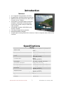
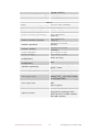
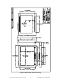
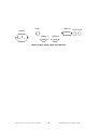
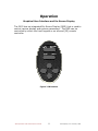
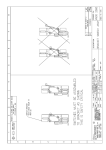
EDL Displays, Inc. Installation and Operation Manual Model 3023 LCD Video Monitor Revised February 20, 2006 www.edldisplays.com 3023 Table of Contents INTRODUCTION 3 FEATURES 3 SPECIFICATIONS 3 INSTALLATION 5 GENERAL 5 UNPACKING 5 MECHANICAL INSTALLATION 5 SIGNAL INPUT CONNECTIONS 6 GRAPHICAL USER INTERFACE AND ON-SCREEN DISPLAY 11 Main Menu 12 PICTURE Submenu 12 OSD Submenu 13 UTILITY Submenu 13 Quick Menu 13 RECOMMENDED USE 15 Safety Precautions and Maintenance 15 Table of Figures FIGURE 1 MODEL 3023 OUTLINE DRAWING FIGURE 2 REAR PANEL INPUT CONNECTIONS FIGURE 3 IR REMOTE 9 10 11 3023 Operation and Maintenance Manual 2 EDL Displays, Inc. February, 2006 Introduction Features • 23.1" diagonal LCD (equivalent to 25" CRT) • Rugged design intended for harsh environments • Metal Enclosure with VESA mount, Rack mount, Console mount or Tabletop • Auto-detection of multiple display formats from 640x480 to 1600x1280, including interlaced formats, with excellent scaling to 1600x1200 native resolution • VESA DPMS compliant, VESA DDC1/2 plug and play compliant • Full-range backlight dimming standard • Backlight stabilization standard • Accepts digital or analog RGB at DVI-I connector, S-video or composite video at DIN or RCA connector Specifications Active area Native resolution Pixel pitch Colors Contrast ratio Luminance Luminance variation Viewing angle, H Viewing angle, V CIE white Response time Type Lifetime 3023 Operation and Maintenance Manual Display 470.4mm x 352.8mm (18.5" x 13.9") 1600 x 1200 0.29mm (0.098 X RGB) 16,777,216 (256 gray levels) 400:1 (typical, at 25°C) 250 cd/m² (typical, at 25°C) 25% (max, at 25°C) ± 80° (typical, for CR ≥ 10) ± 80° (typical, for CR ≥ 10) X = 0.313, Y = 0.329 (typical, at 25°C) tr = 15msec, tf = 10msec (typical, at 25°C) Backlight 6 CCFL 50,000 hrs 3 EDL Displays, Inc. February, 2006 (typical, at 25°C) Electromagnetic Environment Susceptibility Per EN55022 Emissions Per EN55022, FCC class A Safety Design Per UL/C 1950, EN60950 Physical Environment Temperature (operating) 0°C to +50°C Temperature (storage) -20°C to +60°C 90%, condensing Relative Humidity (operating) (to 50°C) 90%, condensing Relative Humidity (storage) (to 60°C) Sea level to 15,000ft Altitude (operating) (4500m) Sea level to 40,000ft Altitude (storage) (12000m) Shock (operating) 30g, 11msec ½ sine Shock (storage) 30g, 11msec ½ sine Weight (in standard 36lbs. (16.3Kg) configuration) Power (in standard 95W configuration) ±1mm, 2 to 13Hz; 0.7g, 13 to Vibration (operating) 100Hz, 3 axes Vibration (storage) TBD Inputs RGB digital (TMDS) or RGB Video signal input analog, 0.7Vp-p into 75Ω, S-video or composite video Separate TTL H&V, Composite TTL Sync signal input H&V, Sync on green Sync selection Automatic DVI-I for RGB, DIN for S-video, RCA jack for composite video Signal connector (RGB via HD-15 or BNC handled with cable options) 3023 Operation and Maintenance Manual 4 EDL Displays, Inc. February, 2006 INSTALLATION GENERAL This section describes the installation of the monitor. The monitor is pre-aligned at the factory to user input requirements. However, there may still be the need for some minor adjustments to be made. Those procedures will be provided later in the Calibration Procedures section. UNPACKING Before unpacking, the carton should be inspected for shipping damage. The carton should be carefully opened and the monitor removed. The monitor should then be carefully inspected for shipping damage. If damage has occurred, the shipping carton and all packing materials should be saved for possible inspection by the shipping company. The shipping company and EDL Displays should be notified at this time. MECHANICAL INSTALLATION The 3023 monitor is designed to be mounted and secured in place on any flat surface. 3023 Operation and Maintenance Manual 5 EDL Displays, Inc. February, 2006 SIGNAL INPUT CONNECTIONS The Model 3023 LCD Monitor accepts both digital and analog video signals at its integrated connector (DVI-I). When connecting the monitor to a digital signal source, it is necessary to use a cable that terminates on the monitor end with a DVI-I connector that mates to the monitor’s connector, and on the source end with a DVI connector appropriate to the source – usually a DVI-D connector. (See cable descriptions below for details.) When connecting the monitor to an analog signal source, it is necessary to use a cable that terminates on the monitor end with a DVI-I connector that mates to the monitor’s connector, and on the source end with an HD-15 connector or with some combination of three to five BNC connectors, as appropriate to the source. (See cable descriptions below for details.) Provided the correct cable is used, the monitor will automatically sense adapt to any analog or digital signals applied. In the case of analog signals, the monitor will automatically sense and adapt to the sync type (sync-on-green, composite separate sync, or separate horizontal and vertical syncs). Video Input Connector Pin Assignments Pin 1 2 3 4 5 6 7 8 9 10 11 12 13 Signal TMDS Data 2 TMDS Data 2 + TMDS Data 2/4 Shield TMDS Data 4 TMDS Data 4 + DDC Clock DDC Data Analog Vertical Sync TMDS Data 1 TMDS Data 1 + TMDS Data 1/3 Shield TMDS Data 3 TMDS Data 3 + Pin 16 17 18 19 20 21 22 23 24 C1 C2 C3 C4 14 15 +5VDC (power input) Ground (5VDC, and analog H and V sync return) C5 3023 Operation and Maintenance Manual 6 Signal Hot Plug Detect TMDS Data 0 TMDS Data 0 + TMDS Data 0/5 Shield TMDS Data 5 TMDS Data 5 + TMDS Clock Shield TMDS Clock + TMDS Clock Analog Red Analog Green Analog Blue Analog Horizontal Sync (or composite H & V sync) Analog Ground (RGB return) EDL Displays, Inc. February, 2006 Cable Options DVI-I to DVI-D This cable should be used when connecting the monitor to a signal source that provides digital outputs by way of a DVI-D connector. DVI-D (output) 1 2 3 4 5 6 7 8 9 10 11 12 13 14 15 16 17 18 19 20 21 22 23 24 Signal TMDS Data 2 TMDS Data 2 + TMDS Data 2/4 Shield TMDS Data 4 TMDS Data 4 + DDC Clock DDC Data Not connected TMDS Data 1 TMDS Data 1 + TMDS Data 1/3 Shield TMDS Data 3 TMDS Data 3 + +5VDC (power input) Ground (5VDC, and analog H and V sync return) Hot Plug Detect TMDS Data 0 TMDS Data 0 + TMDS Data 0/5 Shield TMDS Data 5 TMDS Data 5 + TMDS Clock Shield TMDS Clock + TMDS Clock - DVI-I (input) 1 2 3 4 5 6 7 8 9 10 11 12 13 14 15 16 17 18 19 20 21 22 23 24 DVI-I to 3 BNC This cable should be used when connecting the monitor to an analog source that provides RGB video with composite sync on green by way of three BNC connectors. Source (output) BNC R BNC G BNC B (BNC shells) Signal Analog Red Analog Green (with composite sync) Analog Blue Analog Ground DVI-I (input) C1 C2 C3 C5 DVI-I to 4 BNC This cable should be used when connecting the monitor to an analog source that provides RGB video and separate composite sync by way of four BNC connectors. 3023 Operation and Maintenance Manual 7 EDL Displays, Inc. February, 2006 Source (output) BNC R BNC G BNC B BNC H/C (BNC RGB shells) (BNC H/C shell) Signal Analog Red Analog Green Analog Blue Composite Sync Analog RGB Ground Sync Ground DVI-I (input) C1 C2 C3 C4 C5 15 DVI-I to 5 BNC This cable should be used when connecting the monitor to an analog source that provides RGB video and separate horizontal and vertical sync by way of 5 BNC connectors. Source (output) BNC R BNC G BNC B BNC H/C BNC V (BNC RGB shells) (BNC H/C and V shells) Signal Analog Red Analog Green Analog Blue Horizontal Sync Vertical Sync Analog RGB Ground Sync Ground DVI-I (input) C1 C2 C3 C4 8 C5 15 DVI-I to HD-15 This cable should be used when connecting the monitor to an analog source that provides RGB video and separate horizontal and vertical sync by way of a VGA style HD-15 connector. Source HD-15 (output) 1 2 3 13 14 6, 7, 8 10 3023 Operation and Maintenance Manual Signal Analog Red Analog Green Analog Blue Horizontal Sync Vertical Sync Analog RGB Grounds Sync Ground 8 DVI-I (input) C1 C2 C3 C4 8 C5 15 EDL Displays, Inc. February, 2006 Figure 1 Model 3023 Outline Drawing 3023 Operation and Maintenance Manual 9 EDL Displays, Inc. February, 2006 POWER POWER FUSE SERIAL 1 MENU SERIAL 2 SOURCE UP VIDEO IN DOWN RIGHT NTSC S-VHS LEFT AUTO BRIGHTNESS S-VIDEO VIDEO DVI-I SERIAL 1 SERIAL 2 FUSE 2 AMP SB POWER 85-265 VAC 47-440 Hz VIDEO IN FUSE POWER SERIAL 1 NTSC S-VHS SERIAL 2 Figure 2 Rear Panel input connections 3023 Operation and Maintenance Manual 10 EDL Displays, Inc. February, 2006 Operation Graphical User Interface and On-Screen Display The 3023 has an integrated On-Screen Display (OSD) that is used to control various display and system parameters. The OSD can be controlled by either the front keypad or an infrared (IR) remote controller. Figure 3 IR Remote 3023 Operation and Maintenance Manual 11 EDL Displays, Inc. February, 2006 Keys: AUTO Press to perform an automatic adjustment procedure. Only applicable for analog RGB source modes. SOURCE 1st button press displays the current source. 2nd button press searches for the next available input source in the following order: 1. Digital RGB 2. Analog RGB 3. Composite Video 4. S-Video After S-Video the cycle starts over at Digital RGB. Note: When either the Main Menu or Quick Menu is activated, the SOURCE button acts like the EXIT button to exit the menu or to move up a level. MENU Press to enter the Main Menus or move down to a submenu in the Main Menu. EXIT Leave the menu or move up a level out of a submenu. (IR only – use the SOURCE button to perform this function on the keypad) UP Navigate the menu functions DOWN Navigate the menu functions LEFT Navigate the menu functions and select displays settings RIGHT Navigate the menus function and select display settings Main Menu If the MENU button is pressed while no OSD is active, the Main Menu will be activated. The Main Menu consists of 3 submenus: PICTURE, OSD and UTILITY. Use the LEFT or RIGHT buttons on either the IR remote controller o the keypad to select eh submenu. The DOWN or MENU button will enter the selected submenu. PICTURE Submenu The PICTURE submenu contains different functions depending on the current source selection. If the current source is Digital RGB or Analog RGB, then the PICTURE submenu contains the following functions: 3023 Operation and Maintenance Manual 12 EDL Displays, Inc. February, 2006 • • • • • • • BRIGHTNESS CONTRAST PHASE FREQUENCY H POSITION V POSITION SHARPNESS When the selects source is either of Composite or S-Video, the PICTURE functions are: • BRIGHTNESS • CONTRAST • HUE • SATURATION • SHARPNESS Use the UP or DOWN button to select the desired function. Use the LEFT or RIGHT button to set the value of the selected function. OSD Submenu The OSD submenu contains the following functions: • H POS • V POS • OSD TIMEOUT • LANGUAGE Use the UP or DOWN button to select the desired function. Use the LEFT or RIGHT button to set the value of the selected function. UTILITY Submenu The UTILITY submenu contains the following functions: • FREEZ FRAME • RESET • COLOR TEMPERATURE • INFO Use the UP or DOWN button to select the desired function. Use the LEFT or RUGHT button to set the value of the selected function. Quick Menu If any of the direction buttons are pressed while no OSD is active, the Quick Menu will be activated. The Quick Menu consists of 4 functions: • BRIGHTNESS • CONTRAST • PIP MODE 3023 Operation and Maintenance Manual 13 EDL Displays, Inc. February, 2006 • SCALING MODE The UP or DOWN button will scroll through the Quick Menu to select a function. Use the LEFT or RIGHT buttons to adjust or change the value of the selected function. EXIT or SOURCE will exit the Quick Menu. 3023 Operation and Maintenance Manual 14 EDL Displays, Inc. February, 2006 Recommended Use Safety Precautions and Maintenance • DO NOT OPEN THE MONITOR. There are no user serviceable parts inside and opening or removing covers may expose you to dangerous shock hazards or other risks. Refer all servicing to qualified service personnel. • Do not spill any liquids into the cabinet or use your monitor near water. • Do not insert objects of any kind into the cabinet slots, as they may touch dangerous voltage points, which can be harmful or fatal or may cause electric shock, fire or equipment failure. • Do not place any heavy objects on the power cord. Damage to the cord may cause shock or fire. • Do no place this product on a sloping or unstable cart, stand or table, as the monitor may fall, causing serious damage to the monitor. • The power cable connector is the primary means of detaching the system from the power supply. The monitor should be installed close to a power outlet that is easily accessible. • The inside of the fluorescent tubes located within the LCD monitor contains mercury. Please follow the bylaws or rules of your local municipality to dispose of this tube properly. Immediately unplug your monitor from the wall outlet and refer servicing to qualified service personnel under the following conditions: • When the power supply cord or plug is damaged. • If liquid has been spilled or objects have fallen into the monitor. • If the monitor has been exposed to rain or water. • If the monitor has been dropped or the cabinet is damaged. • If the monitor does not operate normally by following operating instructions. • • • Allow adequate ventilation around the monitor so that heat can properly dissipate. Do not block ventilated openings or place the monitor near a radiator or other heat sources. Do not put anything on top of monitor. Handle with care when transporting. Save packaging for transporting. For optimum performance, allow 20 minutes for warm-up. 3023 Operation and Maintenance Manual 15 EDL Displays, Inc. February, 2006 • • • • • • • • • • • Adjust the monitor height so that the top of the screen is at or slightly below eye level. Your eyes should look slightly downward when viewing the middle of the screen. Position your monitor no closer than 16 inches and no further away than 228 inches from your eyes. The optimal distance is 24 inches for 3023. Rest your eyes periodically by focusing on an object at least 20 feat away. Blink often. Position the monitor at a 90ᑻ angle to windows and other light sources to minimize glare and reflections. Adjust the monitor tilt so that ceiling lights do not reflect on your screen. If reflected light makes it hard for you to see your screen, use an anti-glare filter. Clean the LCD monitor surface with a lint-free, non-abrasive cloth. Avoid using any cleaning solution or glass cleaner! Adjust the monitor’s brightness and contrast controls to enhance readability. Use a document holder placed close to the screen. Position whatever you are looking at most of the time (the screen or reference material) directly in front of you to minimize turning your head while you are typing. Avoid displaying fixed patterns on the monitor for long periods of time to avoid image persistence (after-image effects). Get regular eye checkups. Ergonomics • Adjust the brightness until the background raster disappears. • Do not position the Contrast control to its maximum setting. • Use the preset Size and Position controls with standard signals. • Use the preset Color Setting. • Do not use primary color blue on a dark background, as it is difficult to see and may produce eye fatigue to insufficient contrast. Warning To prevent fire or shock hazards, do not expose this unit to rain or moisture. Also, do not use this unit’s polarized plug with an extension cord receptacle or other outlets unless the prongs can be fully inserted. Refrain from opening the cabinet, as there are high voltage components inside. Refer servicing to qualified service 3023 Operation and Maintenance Manual 16 EDL Displays, Inc. February, 2006 personnel. CAUTION To reduce the risk of electric shock, make sure power cord is unplugged from wall socket. To fully disengage the power to the unit, please disconnect the power cord from the AC outlet. Do not remove cover (or back). No user serviceable parts inside. Refer servicing to qualified service personnel. 3023 Operation and Maintenance Manual 17 EDL Displays, Inc. February, 2006