1
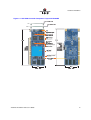
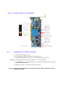
ICP RAID Controller
GDT8546RZ and GDT8586RZ
Four-port Low Profile Serial ATA RAID Controller
Hardware Installation and User’s Guide, Version 1.2
November 2003
Preliminary
IMPORTANT NOTICE - READ BEFORE MAKING USE OF THE INFORMATION CONTAINED HEREIN
This information is provided “as is.” Information in this document is provided solely to enable use of ICP products. Except as provided in ICP vortex’s
Terms and Conditions of sale ICP vortex and/or its suppliers assume no liability whatsoever, and ICP vortex and/or its suppliers disclaim any express
or implied warranty, relating to this information including liability or warranties relating to fitness for a particular purpose, merchantability, satisfactory
quality or infringement of any patent, copyright or other intellectual property right. ICP vortex and/or its suppliers assume no responsibility for any
omissions or any errors which may appear in this document nor does it make a commitment to update the information contained herein.
ICP vortex retains the right to make changes to this document and its products at any time, without notice.
No License, express or implied, by Estoppel or otherwise, to any intellectual property rights is granted by this document. ICP products are not intended
for use in medical, life saving, or life sustaining applications.
Any recommended operating or test methods are correct to ICP’s reasonable knowledge at the time of writing. ICP vortex and/or its suppliers accept
no liability for the implementation of these methods within the user’s environment. The user is responsible for and must satisfy itself that any use
made of this information or ICP products is suitable to its needs.
Any named third party suppliers are provided for information only. The hardware vendor remains solely responsible for the design, sale and
functionality of its product, including any liability arising from product infringement or product warranty. ICP vortex accepts no liability for the quality of
third party suppliers, and cannot guarantee that third party products are suitable or are compatible with ICP products or that third party suppliers will
not change parts so that they are no longer compatible or no longer suitable.
IN NO EVENT WILL ICP VORTEX AND/OR ITS SUPPLIERS BE LIABLE TO THE RECIPIENT OR USER OF THIS INFORMATION FOR ANY LOSS
OF PROFITS, LOSS OF USE, BUSINESS INTERRUPTIONS, INFRINGEMENT OF ANY THIRD PARTY INTELLECTUAL PROPERTY RIGHTS,
LOSS OR CORRUPTION OF DATA, INCIDENTAL, INDIRECT, SPECULATIVE, CONSEQUENTIAL, OR SPECIAL DAMAGES, HOWSOEVER
ARISING AND IRRESPECTIVE OF WHETHER ICP VORTEX HAS ADVANCE NOTICE OF THE POSSIBILITY OF SUCH DAMAGES.
THE LIMITATIONS AND DISCLAIMERS SET FORTH HEREIN WERE AN ESSENTIAL ELEMENT IN ICP VORTEX AGREEING TO SUPPLY THIS
INFORMATION FREE OF CHARGE. THEY SHALL APPLY NOTWITHSTANDING SECTION 1.1 OF THE TERMS AND CONDITIONS OF SALE OF
ICP VORTEX
Hardware Installation and User’s Guide
Contents
1
Getting Started
1.1
1.5
Using the User Documentation Set ............................................................................................... 5
1.1.1
Document Formats ...................................................................................................... 6
About This Guide...........................................................................................................................6
Customer Support Contact Information ......................................................................................... 6
Regulatory and Certification Information ....................................................................................... 7
1.4.1
Product Regulatory Compliance .................................................................................. 7
1.4.2
Product Safety Compliance ......................................................................................... 7
1.4.3
Product EMC Compliance ...........................................................................................7
1.4.4
Product Regulatory Compliance Markings .................................................................. 7
1.4.5
Electromagnetic Compatibility Notices ........................................................................ 7
Warnings and Cautions ................................................................................................................. 9
2
Hardware Installation
2.1
Installation Procedures ................................................................................................................10
2.1.1
Computer System Hardware Requirements ..............................................................10
2.1.2
Installing the ICP RAID Controller .............................................................................12
2.1.3
Changing Jumper Settings ........................................................................................13
Diagnosis Functions ....................................................................................................................16
2.2.1
LED Indicators ...........................................................................................................16
2.2.2
Audible Alarm ............................................................................................................17
2.2.3
Beep Sequences During System Boot ......................................................................18
1.2
1.3
1.4
2.2
3
Hardware Specifications and Features
3.1
3.2
3.3
3.4
3.5
3.6
3.7
3.8
ICP RAID Controller Hardware Features.....................................................................................19
3.1.1
Key Features .............................................................................................................19
Operating System Support ..........................................................................................................21
Supported Hard Drive Technology ..............................................................................................21
Array Roaming Compatibility .......................................................................................................21
PCI Hot Plug................................................................................................................................22
Hot-Plug Disk Drive Support .......................................................................................................22
Auto-detection of Hot-Plug Disk Drives in a Non-Intelligent Drive Enclosure..............................22
RAID Controller Drive Limitations (Host, Array, Logical, and Physical).......................................22
A
Flash Memory Programming
A.1
A.2
A.3
A.4
About Firmware Files..................................................................................................................24
Choosing Update vs. Recover ....................................................................................................24
Setting Jumper J1 / FRU Jumper ...............................................................................................24
Updating or Recovering Firmware Using the FRUU...................................................................25
A.4.1
Creating Firmware Diskettes from the CD-ROM Autorun Menu ................................26
A.4.2
Creating Firmware Diskettes from the Bootable RAID Software Suite CD-ROM ......27
A.4.3
Running the FRUU ....................................................................................................27
Updating Firmware Using XROM ICPCON ................................................................................29
A.5
Hardware Installation and User’s Guide
3
Index
Figures
2-1
2-2
2-3
2-4
2-5
2-6
ICP RAID Controller Component Layout GDT8546RZ............................................................... 11
ICP RAID Controller Layout GDT8586RZ .................................................................................. 12
Installing the ICP RAID Controller into a Computer System....................................................... 13
Jumper Locations and Pin Numbers (GDT8546RZ)................................................................... 14
LED Labels and Colors GDT8546RZ ......................................................................................... 16
LED Labels and colors GDT8586RZ .......................................................................................... 17
Tables
2-1
2-2
2-3
2-4
2-5
3-1
3-2
3-3
4
Controller Jumper Settings GDT8546RZ.................................................................................... 15
Controller jumper Settings GDT8586RZ..................................................................................... 15
LED Description GDT8546RZ .................................................................................................... 16
LED Beschreibungen GDT8546RZ ............................................................................................ 17
Beep Sequences ........................................................................................................................ 18
Hardware Architecture ................................................................................................................ 19
Environmental Specifications ..................................................................................................... 20
RAID Controller Drive Maximum Limitations (GDT8546RZ/GDT8586RZ) ................................. 23
Hardware Installation and User’s Guide
Getting Started
Getting Started
1
Intended Audience
This documentation is intended for users who are experienced in configuring computer
systems with new add-in cards or have had previous experience with ICP RAID
Controllers.
Read and adhere to all warnings, cautions, and notices in this guide and the other
documents in the user documentation set supplied with this product.
1.1
Using the User Documentation Set
User documentation for this product is provided in four separate documents. Not all of
them must be part of the printed documentation. You will find the following documents on
the RAID software suite CD-ROM:
Quick Installation Guide
The Quick Installation Guide provides a high level view of installing and configuring a
RAID controller. Refer to the accompanying Software Guide for more detailed
information.
Hardware Installation and User’s Guide
The Hardware Installation and User’s Guide, or Hardware Guide, covers instructions for
installing an ICP RAID controller and provides a guide to its features and specifications.
For a particular ICP RAID controller, its hardware guide documents compatible RAID
adapters, supported operating systems, standard features and optional features.
Software Installation and User’s Guide
The Software Installation and User’s Guide, or Software Guide, contains:
• Quick installation of the ICP RAID controller software on a newly created bootable
host drive with commonly used operating systems.
• Detailed instructions covering more complex software installation scenarios for all
supported operating systems.
• Instructions for using the RAID Software Suite, the drivers, tools and utilities of the
ICP RAID controller.
The first part of the software guide provides an overview of RAID technology and its
features. Next, the guide documents various installation procedures for an ICP RAID
controller and the RAID Software Suite, depending on the chosen OS configuration. The
software guide then includes descriptions of the utilities, ICP RAID Console (ICPCON)
and ICP RAID Navigator (ICP RAID Navigator), to facilitate the configuration of the
RAID subsystem. Finally, the guide provides details of all product features supported by
Hardware Installation and User’s Guide
5
Getting Started
the software and firmware For further information refer to the Optional Features section
of the appropriate hardware guide since not all features are applicable to all ICP RAID
controllers.
Clustering Guide
The ICP RAID Controller Clustering Guide, or Clustering Guide, describes how to set up
clustering configurations using ICP RAID Controllers and ICP RAID controller software.
Information on Operating Systems, Cluster functionality, and other system details may be
found in their corresponding system manuals.
1.1.1
Document Formats
All documents, with the exception of the quick start guide, are provided on the CD-ROM
in both PDF and HTML format:
• HTML—To view online HTML documents, Click Documentation from the autorun
menu or open <cdromdrive>:\docs\index.htm.
• PDF—Portable Document Format (PDF) documents can be opened, viewed, and
printed with Adobe* Acrobat Reader* (not provided on the CD-ROM).
1.2
About This Guide
This guide contains three sections:
Chapter 1, Getting Started
This chapter covers how to use the different user documents in the user documentation set,
customer support contact information, and regulatory and license agreements covering
this product.
Chapter 2, Hardware Installation
This chapter contains the procedures for installing the ICP RAID controller into a
computer system.
Chapter 3, Hardware Specifications and Features
This chapter covers all the hardware specifications associated with the ICP RAID
controller and its components and any optional RAID features that are supported by the
RAID Software. The software guide covers in detail all software features.
1.3
Customer Support Contact Information
For product support, visit http://www.icp-vortex.com or http://www.vortex.de.
6
Hardware Installation and User’s Guide
Getting Started
1.4
Regulatory and Certification Information
Note: This controller is intended for use in UL Listed computers or equivalent, that have
instructions detailing installation.
1.4.1
Product Regulatory Compliance
The GDT8546RZ and GDT8586RZ RAID controllers, when correctly integrated per this
guide, complie with the following safety and electromagnetic compatibility (EMC)
regulations.
1.4.2
Product Safety Compliance
• CE - Low Voltage Directive (73/23/EEC) (European Union)
1.4.3
Product EMC Compliance
• FCC Part 15, Class A Emissions (USA)
1.4.4
Product Regulatory Compliance Markings
The GDT8546RZ and GDT8586RZ RAID controllers are marked with the following
regulatory markings:
Marking
Description
CE mark for European Union
1.4.5
Electromagnetic Compatibility Notices
1.4.5.1
FCC Verification Statement (USA)
Product Type: GDT8546RZ and GDT8586RZ
This device complies with Part 15 of the FCC Rules. Operation is subject to the following
two conditions: (1) This device may not cause harmful interference, and (2) this device
must accept any interference received, including interference that may cause undesired
operation.
Hardware Installation and User’s Guide
7
Getting Started
This equipment has been tested and found to comply with the limits for a
Class B digital device, pursuant to Part 15 of the FCC Rules. These limits are
designed to provide reasonable protection against harmful interference in a
residential installation. This equipment generates, uses and can radiate radio
frequency energy and, if not installed and used in accordance with the
instructions, may cause harmful interference to radio communications. However,
there is no guarantee that interference will not occur in a particular installation.
If this equipment does cause harmful interference to radio or television reception,
which can be determined by turning the equipment off and on, the user is
encouraged to try to correct the interference by one or more of the following
measures:
-- Reorient or relocate the receiving antenna.
-- Increase the separation between the equipment and receiver.
-- Connect the equipment into an outlet on a circuit different from that to which the
receiver is connected.
-- Consult the dealer or an experienced radio/TV technician for help.
If you make any modification to the equipment not expressly approved by ICP vortex, you
could void your authority to operate the equipment.
Any changes or modifications not expressly approved by the grantee of this device could
void the user’s authority to operate the equipment. The customer is responsible for
ensuring compliance of the modified product.
All cables used to connect to peripherals must be shielded and grounded. Operation with
cables, connected to peripherals that are not shielded and grounded may result in
interference to radio and TV reception.
1.4.5.2
CE Declaration of Conformity (Europe)
We, ICP vortex Computersysteme GmbH, declare under our sole responsibility that the
products:
ICP vortex GDT8546RZ and GDT8586RZ
arein conformity with all applicable essential requirements necessary for CE marking,
following the provisions of the European Council Directive 89/336/EEC (EMC Directive)
and Council Directive 73/23/EEC (Safety/Low Voltage Directive).
The product is properly CE marked demonstrating this conformity and is for distribution
within all member states of the EU with no restrictions.
These products follow the provisions of the European Directives 89/336/EEC and 73/23/EEC.
Dansk Dette produkt er i overensstemmelse med det europæiske direktiv 89/336/EEC & 73/23/
EEC.
Dutch Dit product is in navolging van de bepalingen van Europees Directief 89/336/EEC & 73/23/
EEC.
8
Hardware Installation and User’s Guide
Getting Started
Suomi Tämä tuote noudattaa EU-direktiivin 89/336/EEC & 73/23/EEC määräyksiä.
Français Ce produit est conforme aux exigences de la Directive Européenne 89/336/EEC & 73/
23/EEC.
Deutsch Dieses Produkt entspricht den Bestimmungen der Europäischen Richtlinie 89/336/EEC &
73/23/EEC.
Icelandic Þessi vara stenst reglugerð Evrópska Efnahags Bandalagsins númer 89/336/EEC & 73/
23/EEC.
Italiano Questo prodotto è conforme alla Direttiva Europea 89/336/EEC & 73/23/EEC.
Norsk Dette produktet er i henhold til bestemmelsene i det europeiske direktivet 89/336/EEC &
73/23/EEC.
Portuguese Este produto cumpre com as normas da Diretiva Européia 89/336/EEC & 73/23/EEC.
Español Este producto cumple con las normas del Directivo Europeo 89/336/EEC & 73/23/EEC.
Svenska Denna produkt har tillverkats i enlighet med EG-direktiv 89/336/EEC & 73/23/EEC.
1.5
Warnings and Cautions
This guide and all associated guides in the user documentation set (the Quick Start Guide,
the Hardware Guide, and the Software Guide) should be used by qualified technical
personnel with experience installing and configuring PCI controllers.
Read and adhere to all warnings, cautions, and notices in this guide and all the guides in
the user documentation set supplied with this product.
Warnings
• The connection of a non-shielded equipment interface cable to this equipment will
invalidate the FCC certification of this device and may cause interference levels that
exceed the limits established by the FCC for this equipment. It is the responsibility of
the user to obtain and use a shielded equipment interface cable with this device. If the
equipment has more than one interface connector, do not leave cables connected to
unused interfaces unless otherwise instructed to do so in the user manual.
• Changes or modifications not expressly approved by the manufacturer could void the
user's authority to operate the equipment.
Cautions
• Take precautions to prevent electrostatic discharge (ESD) damage before handling the
ICP RAID controller.
• ESD can damage controller components. Perform the described procedures in this
guide only at an ESD workstation. If no such station is available, you can provide some
ESD protection by wearing an antistatic wrist strap and attaching it to a metal part of
the computer chassis.
Hardware Installation and User’s Guide
9
Hardware Installation
2
Hardware Installation
This chapter provides information on installing the ICP RAID controller, programming
the Flash memory, setting jumpers, and using the LEDs and alarms to diagnose the
controller.
2.1
Installation Procedures
Warning: Shock hazards may be present inside the computer in which this controller is being
installed. Disconnect all power cords to the computer before the removal of any
covers.
Follow the warnings noted in your computer’s user manual before installing this board.
ONLY after reinstallation of all the covers should you reconnect the power cords and
power-up the computer.
Note: Take precautions to prevent electrostatic discharge (ESD) damage before handling the
ICP RAID Controller.
2.1.1
Computer System Hardware Requirements
• Computer with CD-ROM drive
• One available 64-bit/66MHz PCI slot for optimal performance; however, the controller
is backwards compatible with all 33MHz PCI expansion slots.
• PCI 2.2 compliant system BIOS
10
Hardware Installation and User’s Guide
Hardware Installation
Figure 2-1. ICP RAID Controller Component Layout GDT8546RZ
Hardware Installation and User’s Guide
11
Figure 2-2. ICP RAID Controller Layout GDT8586RZ
A0
LEDs on Reverse Side:
S
red
S
= On in Recovery Mode
T
green
T
= Internal Data Transfer
Sun P66 3V3 5V
yellow
Sum = Activity on any Port
green
P66 = 66MHz PCI Clock
green
3V3 = 3.3 Volt available
green
5V = 5 Volt available
A1
B0
B1
Per Port
Data Stat
yellow
red
I²C Connectors for
SAFTE Backplanes
Data= Activity per Port
Stat = Disk failed (if Auto Hot
Plug / Non-Int. Encl.
configured)
C0
C1
D0
D1
Do not use connectors that are
not mentioned
2.1.2
LED Connectors for:
- SUM Activity
- Activity Port A0
- Activity Port A1
- Activity Port B0
- Activity Port B1
- External Alarm
PCI bus speed
Up = Auto (33/66MHz)
Low = Force 33MHz
LED Connectors for:
- SUM Activity
- Activity Port C0
- Activity Port C1
- Activity Port D0
- Activity Port D1
- External Alarm
FRU Jumper
Right = Normal Mode
Left = Recovery Mode
Installing the ICP RAID Controller
1. Power-off the computer system.
2. Disconnect power cord(s) and remove the system cover.
3. Install the ICP RAID controller into an available PCI slot. See Figure 2-3.
Note: Use the appropriate bracket on the controller for your server platform.
4. Using SATA cables, connect the SATA drives to the internal SATA connectors located
on the ICP RAID Controller.
5. Replace the system cover and reconnect power cord(s).
Warning: Attention the controller CPU can get HOT! Controller requires constant airflow for
cooling (min 1m/sec).
Hardware Installation
Figure 2-3. Installing the ICP RAID Controller into a Computer System
PCI
2.1.3
Changing Jumper Settings
The ICP RAID controller normally comes ready to be installed into the computer
motherboard immediately. However, jumper settings are available to:
• Reprogram the RAID firmware that is located in the flash memory of the ICP RAID
controller.
• Set the PCI bus speed (force 33 MHz or auto-negotiate 33/66 MHz).
The board contains 2 jumper blocks to control the functions described in Table 2-1
(GDT8546RZ) and Table 2-2 (GDT8586RZ). See Figure 2-2 (GDT8586RZ) or Figure 2-4
(GDT8546RZ) for jumper locations and pin numbers, and see Appendix A for a detailed
description of jumper J1 / FRU jumper.
Hardware Installation and User’s Guide
13
Hardware Installation
Figure 2-4. Jumper Locations and Pin Numbers (GDT8546RZ)
IOP Mode Select (J1)
1
PCI Bus Speed (J4)
1
Recovery Mode (pins 1-2)
2
Force 33 MHz (pins 1-2)
2
Normal Mode (pins 2-3)
3
14
Auto-negotiate 33 or 66 MHz (pins 2-3)
3
Hardware Installation and User’s Guide
Hardware Installation
Table 2-1. Controller Jumper Settings GDT8546RZ
Jumper Block
J1
J4
Jumper Position
Definition
Jumper on pins [1-2]
IOP is in reset mode with firmware recovery
enabled.
Jumper on pins [2-3]
IOP is in normal run mode.
No jumpers
IOP is in normal run mode.
Jumper on pins [1-2]
PCI bus is forced to 33 MHz.
Jumper on pins [2-3]
PCI bus auto-negotiates 33 MHz or 66 MHz.
No jumpers
PCI bus auto-negotiates 33 MHz or 66 MHz.
J1 - IOP mode select jumper block: This jumper is used to place the IOP in reset, which
enables the flash chip to be programmed to recover resident firmware (FW). See
Appendix A for a detailed description of jumper J1.
J4 - PCI bus speed: Leave this jumper in the default position (pins 2-3 to auto-negotiate
33/66 Mhz) unless instructed to do otherwise by customer support or a specification
update.
Tabelle 2-2. Controller jumper Settings GDT8586RZ
Block Nummer
FRU Jumper
Position
Jumper on pins [1-2]
IOP is in reset mode with firmware recovery
enabled.
Jumper on pins [2-3]
IOP is in normal run mode.
no jumpers
IOP is in normal run mode.
Jumper on pins [1-2]
PCI Bus Speed
Definition
PCI bus is forced to 33 MHz.
Jumper on pins [2-3]
PCI bus auto-negotiates 33 MHz or 66 MHz.
No jumpers
PCI bus auto-negotiates 33 MHz or 66 MHz.
FRU Jumper - IOP mode select jumper block: This jumper is used to place the IOP in
reset, which enables the flash chip to be programmed to recover resident firmware (FW).
See Appendix A for a detailed description of the FRU jumper.
PCI Bus Speed- PCI bus speed: Leave this jumper in the default position (pins 2-3 to
auto-negotiate 33/66 Mhz) unless instructed to do otherwise by customer support or a
specification update.
Hardware Installation and User’s Guide
15
2.2
Diagnosis Functions
The GDT8546RZ and GDT8586RZ have LED indicators, an 80db audible alarm, and
boot-up beep sequences that can help diagnose the controller.
2.2.1
LED Indicators
The LEDs on the controller indicate SATA activity, data transfer, power status, PCI bus
frequency, and reset mode.
Figure 2-5. LED Labels and Colors GDT8546RZ
A:0 A:1 B:0 B:1 T
S
P P66
green
green
red
green
yellow
yellow
yellow
yellow
Table 2-3. LED Description GDT8546RZ
LED
Description
A:0
Indicates activity on SATA port A:0.
A:1
Indicates activity on SATA port A:1.
B:0
Indicates activity on SATA port B:0.
B:1
Indicates activity on SATA port B:1.
T
Indicates data transfer to the controller’s cache memory.
S
When illuminated, the controller's IOP is in reset mode.
P
When illuminated, the controller card is powered on.
P66
When illuminated, PCI bus frequency is 66MHz. When not illuminated, PCI bus
frequency is 33MHz.
Hardware Installation
Abbildung 2-6. LED Labels and colors GDT8586RZ
LEDs on Reverse Side:
S
red
S
= On in Recovery Mode
T
green
T
= Internal Data Transfer
Sun P66 3V3 5V
yellow
Sum = Activity on any Port
green
P66 = 66MHz PCI Clock
green
3V3 = 3.3 Volt available
green
5V = 5 Volt available
Per Port
Data Stat
yellow
red
Data= Activity per Port
Stat = Disk failed (if Auto Hot
Plug / Non-Int. Encl.
configured)
Tabelle 2-4. LED Beschreibungen GDT8546RZ
LED
A0, A1, B0,
B1, C0, C1,
D0, D1
2.2.2
Description
Shows activity on SATA port A0 / A1 / B0 / B1 / C0 / C1 / D0 / D1.
S
When illuminated, the controller's IOP is in reset mode.
T
Indicates data transfer to the controller’s cache memory.
Sum
When illuminated, there is data transfer on one or more SATA ports.
P66
When illuminated, PCI bus frequency is 66MHz. When not illuminated, PCI bus
frequency is 33MHz.
3V3
Shows 3,3 volt current on the PCI bus.
5V
Shows 5 volt current on the PCI bus.
Audible Alarm
An 80db audible alarm, which is controlled by the RAID firmware, is mounted on the
RAID controller to indicate any of the following events:
• State of controller upon boot-up
• Change in the normal state of the array
• Change of controller environmental status (during normal operation)
• Failure of hardware that the controller manages
Hardware Installation and User’s Guide
17
Hardware Installation
If the cause of the event is resolved and/or removed, the audible alarm will cease. You can
also turn off the audible alarm manually through ICPCON or ICP RAID Navigator. If you
use these management tools to silence the alarm, it will only be disabled for the current
event and will be ready to sound again at the next event.
2.2.2.1
Silencing the Audible Alarm in ICPCON
In ICPCON, under Advanced Setup > Configure Controller, press <F4> to silence alarm.
Note: The <F4> option is only available if the alarm has been activated.
2.2.2.2
Silencing the Audible Alarm in ICP RAID Navigator
In ICP RAID Navigator, in the Physical Configuration view, right click on the icon of the
controller requiring alarm deactivation. Click Silence to deactivate alarm. If the alarm has
not been activated, the Silence option will be grayed out.
2.2.3
Beep Sequences During System Boot
During system POST, the audible alarm on the controller will produce one of a number of
beep sequences to indicate the status of the controller. See Table 2-5 for a description of
these beep sequences.
Table 2-5. Beep Sequences
18
Beep Sequence
Status
beep - pause beep, beep, beep
Controller startup was successful.
beep, beep, beep, beep,
....
RAID controller has a problem. A possible cause is disk failure. To
diagnose the problem, run the ICP RAID Console to check the status
of the RAID controller and array.
beep, beep - pause beep, beep - pause - ....
Memory or firmware may have a problem. More details may be
available from the boot message. If necessary, recover the firmware by
following the procedure in Appendix A, “Flash Memory Programming”.
Hardware Installation and User’s Guide
Hardware Specifications and Features
Hardware Specifications and Features
3
This chapter covers all the hardware specifications associated with the ICP RAID
controller and its components. The accompanying Software Guide covers all software
features.
3.1
ICP RAID Controller Hardware Features
This section provides a summary of the key features, configuration options and support
interface technology supported by the ICP RAID Controller.
3.1.1
Key Features
• Supports RAID levels 0, 1, 4, 5 and 10
• Supports up to four/eight hard drives connected to the four/eigth SATA ports on the
•
•
•
•
•
•
•
•
•
controller
Online RAID level migration and capacity expansion without reboot
RAID array roaming
Instant availability and background initialization
Automatic rebuild with private (dedicated) or pooled (global) Hot Fix (spare) drives
Variable data strip size configurable per array
128MB of ECC SDRAM support
Read/write controller caching
Hot Plug disk drive auto detection configurable for non-intelligent enclosures
PCI Hot Plug support
Table 3-1. Hardware Architecture
Component
Features
I/O Microprocessor
The 80303 processor: 100MHz, RISC 64-bit core
Cache Memory
3.3V unbuffered, PC100, ECC SDRAM.128MB
embedded not upgradeable
Flash Memory
3.3v, 32Mb (4MB) flash memory chip is used to store the
RAID firmware
I/O Interface (PCI)
PCI 2.2 compliant, universally keyed for 3.3 and 5 volt
PCI slots
Hardware Installation and User’s Guide
19
Hardware Specifications and Features
Table 3-1. Hardware Architecture
Component
Features
PCI Transfer Rate
528 MB/sec (Burst) DMA to PCI and local buses
PCI Signaling
+5 or +3.3 volt
SATA Controllers
Two/Four Silicon Image Sil3112A SATA controllers,
which each control two serial ports (four ports total) with
speeds up to 1.5 Gbps
Table 3-2. Environmental Specifications
20
Environmental Stress Test
Meets Required Conditions
Operating Temperature
0° C to +55° C
Storage Temperature
-40° C to +70° C
Form Factor (physical dimensions)
GDT8546RZ
Height: 56mm
Length: 167mm
Form Factor (physical dimensions)
GDT8586RZ
Height: 73mm
Length: 209mm
Hardware Installation and User’s Guide
Hardware Specifications and Features
3.2
Operating System Support
The following operating systems are fully validated and supported:
• Microsoft* Windows* XP Professional
• Microsoft Windows 2000 Advanced Server, Windows 2003 (Enterprise) Server
• Novell* NetWare* 6.0
• SCO* Openserver* 5.0.6a
• Red Hat* Linux* 7.3 (2.4 Kernel)
• SCO UnixWare* 7.1.3
• SuSe* Linux 8.0 Professional
The following operating systems are supported with limited compatibility validation:
• Windows 2000 Server
• Novell NetWare 5.x/6.5
• Red Hat Linux 7.2
• Debian* Linux 3.0
• Caldera Linux 3.1.1
• Mandrake* Linux 8.2
• TurboLinux* 7.0 Server
• FreeBSD* 4.5, 4.6 und 5.x
3.3
Supported Hard Drive Technology
The RAID controller supports up to 4/8 hard disk drives connected to the 4/8 SATA ports.
These hard drives must be compliant with the SATA specification 1.0.
3.4
Array Roaming Compatibility
Array Roaming allows the user the ability to move a complete RAID array from one
computer system (for example, computer #1) to another computer system (computer #2)
and preserve the RAID configuration information and user data on that RAID array.
Computer #2 must also have an GDT85x6RZ controller installed. RAID arrays set up with
an GDT85x6RZ controller cannot roam to computers that use other controllers.
Hardware Installation and User’s Guide
21
Hardware Specifications and Features
Note: For a migrated RAID array to be recognized by the new host operating system, the host
system may need to be rebooted.
Warning: RAID arrays set up with an GDT85x6RZ controller cannot roam to computers that
use other controllers (anything other than the GDT85x6RZ). Unpredictable behavior
may include, but is not limited to, data loss or corruption.
3.5
PCI Hot Plug
The GDT8546RZ and GDT8586RZ adapter supports PCI Hot Plug under the following
OS’s:
• Windows 2000 Advanced Server SP2
• Windows 2000 Server
• Novell NetWare 5.1 SP2a
• Novel NetWare 6.x
This ICP RAID controller supports the PCI Hot Plug functionality for the hot replacement
of an adapter. Hot replacement assumes that the drivers for the adapter being replaced are
already loaded.
3.6
Hot-Plug Disk Drive Support
This feature allows for the ability to remove and replace drives while I/O activity is taking
place, provided that both the hard disk drive and backplane fully support Hot-Plug,
without interruption of operations on any other drives. It supports the Hot Plug of new
drives in non-intelligent enclosures as detailed in Section 3.7.
3.7
Auto-detection of Hot-Plug Disk Drives in a NonIntelligent Drive Enclosure
This feature allows the use of non-intelligent disk enclosures (requires truly hot-pluggable
disk drives and backplane connectors) as though they were intelligent enclosures. This
feature is configurable and allows the user to set up non-intelligent enclosures to detect
the insertion or removal of hot plug disk drives and report the event to the RAID
firmware. The RAID configuration is automatically updated to the new configuration.
Access this feature through the Advanced Setup menu of ICP RAID Console.
3.8
RAID Controller Drive Limitations (Host, Array,
Logical, and Physical)
The following are limitations assuming the following:
• Four/eigth SATA ports
22
Hardware Installation and User’s Guide
Hardware Specifications and Features
• Cabling that meets SATA specifications 1.0
Physical drives are limited by the number of ports (four/eigth) on the RAID controller.
Each physical drive must be connected to one of the SATA ports. The maximum number
of array drives is two. A RAID array drive requires a minimum of two hard disk drives
(or logical drives). Therefore the maximum RAID array drive limitation for the
GDT8546RZ and GDT8586RZ controller is the physical drive limit divided by two.
Each RAID array drive (up to two) can contain up to a maximum of two host drives. This
means that the GDT8546RZ and GDT8586RZ controller has a maximum limitation of
four/eigth host drives. Also, each array drive must have at least one host drive. A host
drive can only be associated with (or reside on) a single array drive.
Table 3-3. RAID Controller Drive Maximum Limitations (GDT8546RZ/
GDT8586RZ)
Per RAID
Controller
Per Array Drive
Per Host Drive
Physical Disk Drives
4/8
4/8
4/8
RAID Array Drives
2/4
N/A
1
RAID Host Drives
4/8
2
N/A
Drive Type
Hardware Installation and User’s Guide
23
Flash Memory Programming
Flash Memory Programming
A.1
A
About Firmware Files
The firmware image that is stored in the flash memory of the RAID controller includes the
controller BIOS and the ICP RAID Console (ICPCON) software. Refer to the Software
Guide for more details about ICPCON.
The current firmware file is on the RAID Software Suite CD-ROM. To get the latest
firmware for the RAID controller, visit our web site at: http://www.icp-vortex.com or
http://www.vortex.de. You can use firmware files to update or recover the firmware image
on the controller. See Section A.2 for more information.
Firmware files are in the format SRC_RXFW.xxx, where the file extension xxx indicates
the version stepping. From ICPCON or ICP RAID Navigator, the firmware version is
displayed in the format x.yy.zz-A000 (for example, 2.34.00-R02D).
A.2
Choosing Update vs. Recover
When programming the firmware, you must decide whether an update or a full recovery is
more appropriate. If firmware recovery is required, you may need to change a jumper
setting. See Section A.3 for details on how to set jumper J1 / FRU jumper.
Table A-1. Differences Between Update and Recover
Symptom or Scenario
A.3
Possible Cause
Probability
Suggested Action
New firmware is available
on http://www.icpvortex.com or http://
www.vortex.de.
A new version of ICPCON is
available or improvements
have been made to the
controller BIOS.
ICP vortex
provides
updates as
needed
Update
The controller state is
DEFECT when using the
FRUU. See Section A.4.
Firmware is damaged.
Rare
Recover
The firmware update
procedure was
interrupted before
successful completion.
Power loss or spike during the
update procedure.
Rare
Recover
Setting Jumper J1 / FRU Jumper
The J1 jumper must be set for flash recovery mode (pins 1-2) to recover the firmware. For
all other operations, including firmware update, normal mode (pins 2-3) is required. See
Figure 2-1 for the jumper location and Figure A-1 below for jumper positions.
24
Hardware Installation and User’s Guide
Flash Memory Programming
Refer to Section A.2 for help in deciding whether the firmware needs a recovery or
update.
Figure A-1. Jumper Positions for Flash Update and Recovery
J1
1 2 3
1 2 3
Normal-Run
(Update)
Flash Recovery
(Recover)
Warning: Shock hazards may be present inside the unit in which this controller is being
installed. Disconnect all power cords to the unit before removal of any covers.
Follow the warnings noted in your computer’s user or service manual before
installing this board. ONLY after all the covers are reinstalled should you reconnect
the power cords and power up the unit.
1. Take all precautions to prevent ESD damage before handling the ICP RAID
Controller.
2. Power off all system components and disconnect their power cords.
3. Remove the cover from the system to gain access to the PCI slots.
4. Remove the ICP RAID Controller from your system.
5. On jumper block J1 / FRU jumper, move the jumper to position 1-2 for firmware
recovery or to position 2-3 for firmware updates. See Figure A-1 and Figure 2-1 for
details.
6. Re-install the adapter in the PCI slot in which it was previously installed.
7. Replace the cover, reconnect all power cords and power up the system.
A.4
Updating or Recovering Firmware Using the FRUU
This section explains how to use the Firmware Recovery and Update Utility (FRUU) to
update or recover the firmware on the RAID controller. For help in choosing between
update and recover, see Section A.2.
Hardware Installation and User’s Guide
25
Flash Memory Programming
The FRUU is available from these locations:
Table A-2. FRUU Locations and Descriptions
FRUU Location
Run the FRUU on diskettes
created from:
• The Windows autorun
menu of the RAID
Software Suite CD-ROM
OR
• The ‘Create Diskettes’
option from the bootable
CD
Run the FRUU directly from
the bootable RAID Software
Suite CD-ROM
A.4.1
Summary
More Information
Create the two diskettes described
below and then boot the computer with
diskette 1:
• Diskette 1—The bootable Firmware
Recovery and Update Utility
(FRUU).
• Diskette 2—The firmware file. You
can:
— Create the firmware diskette
from the firmware file that is on
the CD-ROM.
OR
— Download the latest firmware
file from http://www.icpvortex.com or http://
www.vortex.de.
Boot directly from the RAID Software
Suite CD-ROM to update or recover the
firmware image on the controller with the
original firmware file that shipped on the
CD.
• See Section A.4.1
to create the
diskettes from the
Windows autorun
menu.
• See Section A.4.2
to create the
diskettes from the
Bootable RAID
Software Suite
CD-ROM.
• See Section A.4.3
for information on
running the FRUU.
See Section A.4.3 for
information on running
the FRUU.
Creating Firmware Diskettes from the CD-ROM Autorun
Menu
1. Insert the RAID Software Suite CD-ROM into a Windows computer.
2. After the Main Menu loads automatically, click ‘Utility Diskettes.’
3. Click ‘Firmware Recovery Utility.’ A DOS window will display prompting you to
insert a blank floppy diskette.
4. Insert the blank diskette, then press <Enter>.
5. After the file transfer is complete, remove the diskette from the computer and label it.
6. Insert a second blank diskette into the computer.
7. Download the latest firmware file from http://www.icp-vortex.com or http://
www.vortex.de and copy it to the second floppy diskette. Proceed to Section A.4.3 for
information on running the FRUU.
OR
Click Firmware Diskette to get the firmware file from the RAID Software Suite CDROM, then complete the remaining steps in this procedure.
8. Click ‘Firmware Diskette.’ A DOS window will display prompting you to insert a
blank floppy diskette.
9. Verify that a blank diskette is inserted, then press Enter.
26
Hardware Installation and User’s Guide
Flash Memory Programming
10. After the file transfer is complete, remove the firmware diskette from the computer
and label it.
A.4.2
Creating Firmware Diskettes from the Bootable RAID
Software Suite CD-ROM
1. If necessary, change your computer’s BIOS setting so that the system boots from the
CD-ROM.
2. Boot the computer from the RAID Software Suite CD-ROM.
3. Select ‘Create Diskettes’ and press Enter.
4. Select ‘Firmware Diskettes’ and press Enter.
5. Select ‘Bootable Firmware Recovery Floppy’ and press Enter.
6. Insert a blank floppy Diskette, then select ‘Yes’ and press Enter to begin the file
transfer.
7. After the file transfer is complete, select ‘OK’, then press Enter.
8. Remove the first diskette and label it.
9. From a computer that has an internet connection, download the latest firmware file
from http://www.icp-vortex.com or http://www.vortex.de and copy it to a second
floppy diskette. Proceed to Section A.4.3 for information on running the FRUU.
OR
Insert a second blank diskette into the computer, then complete the remaining steps in
this procedure.
10. Select ‘Create Diskettes’ and press Enter.
11. Select ‘Firmware Diskettes’ and press Enter.
12. Select ‘Firmware File’ and press Enter.
13. Verify that your second blank floppy Diskette is inserted, then select ‘Yes’ and press
Enter to begin the file transfer.
14. After the file transfer is complete, select ‘OK’, then press Enter.
15. Remove the first diskette and label it.
16. Proceed to Section A.4.3 for information on running the FRUU.
A.4.3
Running the FRUU
1. Choose between firmware update and firmware recovery. See Section A.2.
2. Set the ICP RAID controller’s IOP to normal for firmware updates or to reset for
firmware recovery. See Section A.3.
3. If running the FRUU from the RAID Software Suite CD-ROM, change your
computer’s BIOS setting so that your system boots from the CD-ROM.
Hardware Installation and User’s Guide
27
Flash Memory Programming
4. Insert the RAID Software Suite CD-ROM.
OR
Insert the bootable FRUU floppy.
5. Boot the computer.
6. If booting from the RAID Software Suite CD-ROM, select Firmware Management
from the Main Menu and press <Enter>.
OR
If booting from the FRUU bootable floppy diskette, insert the second firmware
diskette after the computer finishes booting from the first diskette, then select “Y” (for
Yes) and press Enter to load the firmware file.
7. View the summary information on the screen. The Flash Recovery and Update Utility
detects any RAID controllers and lists them in the order that they are found.
Note: Notice the STATE column in this screen. The state of each controller is
NORMAL (the word is green if booting from CD), RESET (the word is red if booting
from CD), or DEFECT (the word is red if booting from CD).
— If the controller state is NORMAL—You can perform a firmware update. If you
need to perform a firmware recovery, shut down the system and start again with
step 4 above. Refer to Section A.3 to set the jumper in reset mode.
— If the controller state is RESET—You can perform a firmware recovery. If you
only need to perform a firmware update, shut down the system and start again with
step 4 above. Refer to Section A.3 to set the jumper in normal mode.
— If the controller state is DEFECT—You must perform a firmware recovery.
8. Type a controller number to start the update or recovery process for the firmware on
that controller. You do not need to press Enter after typing the number. You will see
messages showing the progress of the firmware update or recovery. The entire process
may take several minutes.
9. If necessary, reset the jumper to normal mode.
a. Power off all system components and disconnect power cords.
b. Remove the system cover.
c. Remove the ICP RAID Controller from your system.
d. On Jumper block J1 / FRU jumper, move the jumper from position 1-2 to position
2-3 (see Section A.3). Reinstall the ICP RAID Controller in the PCI slot in which
it was previously installed. Reconnect the drives to the controller.
e. Replace the cover, reconnect all power cords and power up the system.
10. Change your computer’s system BIOS setting so that your system boots normally (not
from the CD-ROM).
28
Hardware Installation and User’s Guide
Flash Memory Programming
A.5
Updating Firmware Using XROM ICPCON
There are two options for updating the firmware, BIOS and XROM ICPCON currently
programmed on the flash memory of the RAID controller:
• Use the ICP RAID Console (ICPCON) to update the firmware image as explained in
this section. If your OS does not support the firmware update with ICPCON, use the
Firmware Update and Recovery Utility (FRUU) as described in the next bullet item.
• Run the Firmware Recovery and Update Utility (FRUU) from a bootable CD or
diskette as explained in Section A.4.
You cannot use ICPCON to recover the firmware, but you can use it to update the
firmware. For information about update vs. recover, see Section A.2.
Note: The Firmware Update option is not available when ICPCON is accessing the RAID
Controller remotely.
Note: A firmware upgrade with help of XROM ICPCON is only possible, if only the minor
version number changes, e.g. if you update from 2.39.00 to 2.39.01. For major updates, a
new ICPCON for the new firmware must be loaded (e.g. Upgrade from 2.39.00 to
2.40.00)
To Update the Firmware with ICPCON
1. Download the firmware image containing the latest programs/drivers from the
website. Also download the latest tools for your operating system including ICPCON.
Format a 3.5” HD disk (1.44MB) and copy the firmware file and ICPCON onto the
disk.
2. With the adapter installed in the system, start the new ICPCON under your OS.
3. Select the applicable RAID controller and press <Enter>.
4. If the Express Setup menu is displayed, press <F4> to display the Advanced Setup
menu. Select the menu option, Configure Controller and press <Enter>. Insert the
floppy containing the latest firmware file into the floppy disk drive.
5. From the Configure Controller submenu, select Firmware Update and press <Enter>.
6. When prompted for the path, type in 'A:' and press Enter. After finding the file,
ICPCON displays the name, description and version of the firmware. Press <Enter>.
7. ICPCON reads and checks the firmware file, then displays a warning. Press <Y> to
confirm the firmware update.
8. ICPCON programs the flash eprom.
Warning: Do not interrupt the update process to avoid damaging the firmware image in the
Flash. If the firmware is interrupted you will need to follow the firmware recovery
process in the next section.
After ICPCON indicates that the update is complete, press any key.
9. The focus returns to the Configure Controller submenu. Press <Esc> several times to
close the menus and press <Y> to quit ICPCON.
Hardware Installation and User’s Guide
29
Flash Memory Programming
10. ICPCON detects the firmware update and requires a system reboot. Press any key to
reboot.
When the update process has completed, reboot the computer for the change to take effect.
During boot up, the system displays the updated firmware version. You can also relaunch
ICPCON and select the applicable RAID controller to view its new firmware version at
the bottom of the console (for example, FW:2.39.yy-Rzzz).
You can also use the OS version of ICPCON to update the firmware. Refer to the ICP
RAID Console chapter of the Software Guide for more details.
Copyright 2003 ICP vortex Computersysteme GmbH. ICP "Intelligent Computer
Peripherals" is a registered trademark.*Other names and brands may be claimend as
the property of others.
30
Hardware Installation and User’s Guide