1
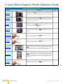
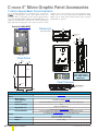
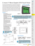
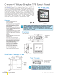
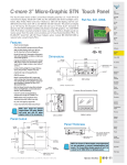
C-more Micro-Graphic Panels Selection Guide
C-more Micro-Graphic Panels
Part Number
EA1-S3ML
NonTouch
EA1-S3ML-N
Description
Price
3.1-inch C-more Micro-Graphic Touch Panel with green and red LED backlights. Supports 5
selectable backlight colors (Green, Red, Amber, Yellow and Lime). STN LCD monochrome, 128
x 64 dot display. Has 5 user-defined function keys with LED indicators. Power is supplied to the
panel through the serial communication port connection when used with DirectLOGIC PLCs having an RJ12 communication port. EA-MG-SP1 (power supply with serial option module)
required when connecting to third party PLCs. NEMA 4/4X, IP65 (when mounted correctly; for
indoor use only).
<--->
3.1-inch C-more Micro-Graphic Non-Touch Panel with green and red LED backlights. Supports
5 selectable backlight colors (Green, Red, Amber, Yellow and Lime). STN LCD monochrome, 128
x 64 dot display. Has 5 user-defined function keys with LED indicators. Power is supplied to the
panel through the serial communication port connection when used with DirectLOGIC PLCs having an RJ12 communication port. EA-MG-SP1 (power supply with serial option module)
required when connecting to third party PLCs. NEMA 4/4X, IP65 (when mounted correctly; for
indoor use only).
<--->
EA1-S3MLW-N
<--->
EA1-S6ML
EA1-S6MLW
EA1-T6CL
5.7-inch C-more Micro-Graphic Touch Panel with STN LCD monochrome, 320x240 dot display.
The panel has white and red LED backlights. Supports 5 selectable backlight colors (White,
Pink1, Pink2, Pink3, and Red). Includes 5 user-defined function keys with LED indicators. 2 built
in serial Ports (RS-232 RJ12 port and 15 pin D-sub RS-232/422/485). NEMA 4/4X, IP65 (when
mounted correctly; for indoor use only).
5.7-inch C-more Micro-Graphic Touch Panel with TFT Color LCD, 320 x 240 dot, 32,768 color
display with LED backlight. 5 user-defined function keys with LED indicators. Two built-in ports
(USB Type-B port and 15-pin D-sub RS-232/422/485 port). Display supports Portrait and
Landscape modes. NEMA 4/4X, IP65 (when mounted correctly; for indoor use only).
EA1-xnxLx-x
Display Type:
S: STN
T: TFT
Backlight Color:
(STN Panels only)
blank: red, green, amber, lime, yellow
W: white, pink1, pink2, pink3, red
Proximity
Sensors
Photo
Sensors
Limit
Switches
<--->
Encoders
Current
Sensors
Pressure
Sensors
<--->
Temperature
Sensors
Pushbuttons/
Lights
Process
<--->
Relays/
Timers
Comm.
Terminal
Blocks &
Wiring
<--->
Power
Circuit
Protection
Enclosures
Tools
Display Color:
M: Monochrome
C: Color
Backlight Type:
L: LED
Pneumatics
Safety
Appendix
Product
Index
Features:
blank: Touch Screen
N: Non Touch Screen
Volume 14
w w w. a u to m a t i o n d i re c t . c o m / C - m o re - m i c ro
Steppers/
Servos
Motor
Controls
C-more Micro-Graphic Panel Part No. Key:
Display Size:
3: 3.1”
4: 4.1“
6: 5.7”
Series Name:
EA1: C-more Micro-Graphic
Drives
Motors &
Gearbox
3.1-inch C-more Micro-Graphic Non-Touch Panel with High Contrast white and red LED backlights. Supports 5 selectable backlight colors (White, Pink1, Pink2, Pink3 and Red). STN LCD
monochrome, 128 x 64 dot display. Has 5 user-defined function keys with LED indicators. Power
is supplied to the panel through the serial communication port connection when used with
DirectLOGIC PLCs having an RJ12 communication port. EA-MG-SP1 (power supply with serial
option module) required when connecting to third party PLCs. NEMA 4/4X, IP65 (when mounted correctly; for indoor use only).
5.7-inch C-more Micro-Graphic Touch Panel with STN LCD monochrome, 320x240 dot display.
The panel has red and green LED backlights. Supports 5 selectable backlight colors (Red, Green,
Amber, Lime, and Yellow). Includes 5 user-defined function keys with LED indicators. 2 built in
serial Ports (RS-232 RJ12 port and 15 pin D-sub RS-232/422/485). NEMA 4/4X, IP65 (when
mounted correctly; for indoor use only).
Field I/O
Soft
Starters
<--->
4-inch C-more Micro-Graphic Touch Panel with TFT Color LCD, 320 x 240 dot, 32,768 color
display with LED backlight. 5 user-defined function keys with LED indicators. Two built-in ports
(USB Type-B port and 15-pin D-sub RS-232/422/485 port). Display supports Portrait and
Landscape modes. NEMA 4/4X, IP65 (when mounted correctly; for indoor use only).
Programmable
Controllers
C-more &
other HMI
EA1-S3MLW
EA1-T4CL
Systems
Overview
Software
3.1-inch C-more Micro-Graphic Touch Panel with High Contrast white and red LED backlights.
Supports 5 selectable backlight colors (White, Pink1, Pink2, Pink3 and Red). STN LCD monochrome, 128 x 64 dot display. Has 5 user-defined function keys with LED indicators. Power is
supplied to the panel through the serial communication port connection when used with
DirectLOGIC PLCs having an RJ12 communication port. EA-MG-SP1 (power supply with serial
option module) required when connecting to third party PLCs. NEMA 4/4X, IP65 (when mounted correctly; for indoor use only).
NonTouch
Company
Information
Operator Interface
e11-11
Part #
Index
C-more Micro-Graphic Panels Selection Guide
C-more Micro-Graphic Panel Accessories
Part Number
Description
Price
EA-MG-BZ1
8-button keypad bezel for C-more 3” Micro-Graphic panels, with 4 arrow adjust keys, and
ESCAPE, MENU, CLEAR and ENTER buttons. Helps to reduce screen wear in heavy-duty applications where operators can use the keypad. Designed for easy drop-in of the Micro-Graphic
panels.
<--->
20-button keypad bezel with numeric keypad for C-more 3” Micro-Graphic panels, with 4 arrow
adjust keys, and ESCAPE, MENU, CLEAR and ENTER buttons. Helps to reduce screen wear in
heavy-duty applications where operators can use the keypad to enter numeric data. Designed for
easy drop-in of the Micro-Graphic panels.
<--->
EA-MG-P1
Optional DC Power Adapter for C-more 3” Micro-Graphic panels. Required when using third
party PLCs, or when using 24 VDC power instead of the 5 VDC supplied from the RJ12 connector of a Productivity Series, CLICK or Direct LOGIC PLC.
<--->
EA-MG-SP1
Optional Serial Port with DC Power Adapter for C-more 3” Micro-Graphic panels. Serial port is
a D-Sub 15-pin RS-232/RS-422/485 connector. Required when using RS422, RS485 or third
party PLCs.
<--->
EA-MG-COV-CL
Optional clear screen overlay used to protect C-more 3” Micro-Graphic displays from minor
scratches and wear. Package contains 5 clear screen overlays.
<--->
EA-4-COV2
Optional clear screen overlay used to protect C-more 4” Micro-Graphic displays from minor
scratches and wear. Package contains 3 clear screen overlays.
<--->
EA-MG6-BZ2
For Landscape (Horizontal) Mounted Panels. 20-button keypad bezel with numeric keypad for
C-more 6” Micro-Graphic panels, 4 arrow adjust keys, and ESCAPE, MENU, CLEAR and ENTER
buttons. Helps to reduce screen wear in heavy-duty applications where operators can use the
keypad to enter numeric data. Designed for easy drop-in of the Micro-Graphic panels.
<--->
EA-MG6-BZ2P
For Portrait (Vertical) Mounted Panels. 21-button keypad bezel with numeric keypad for
C-more 6” Micro-Graphic panels, 4 arrow adjust keys, and ESCAPE, MENU, CLEAR and
(2) ENTER buttons. Helps to reduce screen wear in heavy-duty applications where operators can use the keypad to enter numeric data. Designed for easy drop-in of the MicroGraphic panels.
<--->
EA-6-COV2
Optional clear screen overlay used to protect C-more 6” Micro-Graphic displays from minor
scratches and wear. Package contains 3 clear screen overlays.
<--->
EA-MG-BZ2
Volume 14
e11-12
Operator Interface
1 - 80 0 - 633 - 0405
C-more 6” Micro-Graphic STN Touch Panel
Model EA1-S6MLW C-more 6” Micro-Graphic touch panel has a 5.7-inch STN
LCD monochrome 320 x 240 dot display and five selectable LED-driven backlight
colors including White, Pink1, Pink2, Pink3 and Red. It features five user-defined
function keys, each key with a user-defined red LED indicator. The panel can
display up to 40 lines by 80 characters of static text and up to 40 lines by 40 characters of dynamic text with embedded variables and phrases mixed with graphics
in landscape orientation. Portrait orientation can display 53 lines by 60 characters
of static text and 40 lines by 40 characters of dynamic text. It is rated UL for use on
a flat surface of Type 1, 4X enclosure (for indoor use only). The C-more 6” MicroGraphic STN panels are powered from a Class 2, 12-24 VDC power supply or can
operate in low-power mode* when powered from the serial communications port
of select AutomationDirect PLCs.
Features
• Touch screen display
• Free downloadable programming software
• 320 x 20 Dot display with up to 40 lines
by 80 characters of text and graphics in
landscape mode
• Up to 40 lines by 40 characters of dynamic
text with embedded variables and phrases
mixed with graphics
• 5 programmable function keys can change
with every screen. Can increment / decrement values, trigger recipes, view index of
screens.
• 5-Color LED backlight for longer lifetime;
Green, Red, Amber, Yellow and Lime
• 2 optional keypad bezels, 20-button
landscape and 21-button portrait
• Optional replaceable clear screen overlay
• 1,792 KB memory
• Built-in RJ12 serial communications port
• Built-in 15-pin serial communications port
• Built-in Alarm Control setup that activates
beep, backlight flash, customized alarm
banner, and red LED blinking
• 0 to 50 °C (32 to 122 °F) operating
temperature range (IEC 60068-2-14)
• NEMA 4/4X, IP65 compliant when
mounted correctly, indoor use only
• UL, cUL & CE agency approvals
• 2-year warranty from date of purchase
C
UL
R
Part No. EA1-S6MLW
Shown in Landscape (Horizontal) mode
C-more &
other HMI
Drives
Soft
Starters
Motors &
Gearbox
<--->
6.295
[159.9]
MOUNTING CLIP
(4) places
2.13
1.453
[54.1] 1.689 [36.9]
[42.9]
.236
[6.0]
GASKET
Proximity
Sensors
Photo
Sensors
Limit
Switches
Encoders
6.850
[174.0]
Pressure
Sensors
Pushbuttons/
Lights
Process
Relays/
Timers
5.331
[135.4]
4.770
[121.3]
Comm.
Terminal
Blocks &
Wiring
+0.04
0.256
[6.5]
0.260
[6.6]
Motor
Controls
Temperature
Sensors
6.339 –0.00
+1
161.0 –0
Steppers/
Servos
Current
Sensors
NOTE: Don’t forget the optional
keypad bezels shown in the
Accessories section.
Panel Cutout
Programmable
Controllers
Software
*NOTE: When EA1-S6ML or EA1-S6MLW is powered through Port1 from a connected PLC or
PC, the screen brightness is diminished because the panel is running in Low-Power Mode.
For full brightness, connect an external Class 2, 12-24 VDC power source to the 6”
panel’s power connection. Low-Power Mode should be used during initial programming
only. Connect an external Class 2, 12-24 VDC power source when the panel is installed
in its application.
Units: inches [mm]
Systems
Overview
Field I/O
US
Dimensions
Company
Information
Panel Thickness
0.256
[6.5]
R .118 [R3]
CUTOUT
OUTLINE
+0.04
4.811 –0.00
Power
Circuit
Protection
Enclosures
ENCLOSURE MOUNTING
THICKNESS RANGE
0.04” - 0.2” [1 - 5mm]
CUTOUT
NOTE: The C-more 6” Micro-Graphic cutout dimensions are
not equivalent to previous AutomationDirect text panels.
The C-more 6” Micro-Graphic panels will not fit in cutouts
for DV-1000, EZText, Optimate panels or C-more 6” panels.
0.260
[6.6]
Volume 14
w w w. a u to m a t i o n d i re c t . c o m / C - m o re - m i c ro
Pneumatics
Safety
BEZEL
OUTLINE
+1
122.2 –0
Tools
Operator Interface
e11-49
Appendix
Product
Index
Part #
Index
C-more 6” Micro-Graphic Panels Overview
EA1-S6ML
Overview
C-more 6” Micro-Graphic panels are joined by a full
color, TFT model! C-more 6” Micro-Graphic panels
offer touch screen capability and customizable graphics.
Two optional Keypad Bezels are available for either
Horizontal or Vertical panel orientation.
Installing the software and configuring the C-more 6”
Micro-Graphic panel is simple. You will need the
following to successfully connect and configure a
project for the panel:
• C-more 6” Micro-Graphic panel
• C-more Micro-Graphic Programming Software EA-MGPGMSW (Downloadable version available from the
AutomationDirect web site at no charge.)
• C-more Micro-Graphic USB Programming Cable such as
USB-CBL-AB6, used to connect between a PC and the
Micro-Graphic panel’s built-in serial port. The panel will
operate in Low-Power mode when powered by the PC
and the screen brightness is diminished.
• Power source – An external Class 2, 12-24 VDC power
source is required for normal High-Power operation.
Recommended power
supplies are AutomationDirect part numbers
PSC-24-015 or PSC-24-030.
• Personal computer – to run the C-more Micro-Graphic
programming software
• Communications Cable (serial) – to connect the C-more
Micro-Graphic panel to your controller.
Drivers for your Controller
C-more 6” Micro-Graphic panels have the following
drivers available for connection to Productivity Series,
CLICK, DirectLOGIC and many other devices:
• AutomationDirect Productivity Series
• AutomationDirect Do-more
• AutomationDirect CLICK (Modbus)
• DirectLOGIC K-sequence, DirectLOGIC DirectNET,
DirectLOGIC Modbus (Koyo Addressing)
• Modbus RTU
• Allen Bradley DF1 Full Duplex, Allen Bradley DF1 Half
Duplex, Allen Bradley PLC5 DF1, AB DH485
• Omron Host Link (C200 Adapter, C500)
Omron FINS serial (CJ1, CS1)
• GE SNPX (90/30, 90/70, Micro 90, VersaMax Micro)
• Mitsubishi Melsec FX
• Siemens PPI
• Entivity Modbus RTU
• AutomationDirect GS Drives
• AutomationDirect SOLO Temperature Controllers
• Mitsubishi Q/QnA
EA1-T6CL
Systems
Overview
Programmable
Controllers
Field I/O
In addition to the simple panel configuration
software, a very helpful feature is the built-in project
simulator. The project simulator allows you to view your
project on the PC screen as it would appear on the
panel and to test all your screens before downloading
the project to the panel. You can simulate your entire
project at any stage of development. With version 2.50
or later, simulate the function keys and keypad bezel.
Getting started
EA1-S6MLW
Company
Information
<--->
Shown in Landscape
(Horizontal) mode
<--->
<--->
Shown in Portrait
(Vertical) mode
Shown in Portrait
(Vertical) mode
NOTE: EA1-T6CL requires Software and Firmware Version 2.50 or later.
Software and Firmware Version 2.0 or later is required with models
EA1-S6ML and EA1-S6MLW.
Available for free download at www.automationdirect.com.
Bitmaps
• 320 X 240 pixel graphical display supports bitmaps
• Use bitmap images of pushbuttons, switches, indicators, your company logo
• Use provided library of bitmaps
• Create your own library of bitmaps
Text - 40 lines
• 40 lines by 80 characters of static text in Landscape Orientation
• 53 lines by 60 characters of static text in Portrait Orientation
• Look up text, scroll up to 128 characters
• 40 lines by 40 characters of dynamic text, embedded variables, on/off phrases,
scroll up to 40 characters
• Scroll text object with up to 128 characters
Beep
Drives
Soft
Starters
Motors &
Gearbox
Motor
Controls
Proximity
Sensors
Photo
Sensors
Limit
Switches
Encoders
Current
Sensors
Pressure
Sensors
• Beep to indicate an alarm
• Beep for a special message
• Beep to verify when button is pressed
Temperature
Sensors
Bar graphs
Pushbuttons/
Lights
Data entry
• Line, vertical, horizontal, skinny, fat, multiple
Process
• Pop-up numeric key pad on the screen
• Increment/decrement a value by touching arrows
• Two optional keypad bezels, Landscape and Portrait
Relays/
Timers
Recipes
Comm.
Each recipe button transfers up to 99 values from PLC source registers to PLC
destination registers and/or from the recipe table to PLC destination registers.
5 dynamic background colors - EA1-S6ML and EA1-S6MLW
Screen background can be controlled by the program to choose one of five colors
depending upon the model. Choices for model EA1-S6ML are green, lime, yellow,
amber and red. Model EA1-S6MLW background colors include white, pink1, pink2,
pink3 and red . For example, use a red background for an alarm condition or a yellow background on a caution screen that will be easily noticed.
EA1-S6MLW
Power
Circuit
Protection
Enclosures
Tools
Pneumatics
Appendix
C-more Micro-Graphic supports up to 999
screens. Screen quantity is limited by memory usage which is determined by the
total bitmaps, objects, etc. that are used.
Volume 14
Operator Interface
Terminal
Blocks &
Wiring
Safety
The TFT panel has a palette of 32K colors available to make full use of color for objects and
bitmaps as well as backgrounds.
Up to 999 Screens
w w w. a u to m a t i o n d i re c t . c o m / C - m o re - m i c ro
C-more &
other HMI
Steppers/
Servos
Features
EA1-S6ML
32K Colors - EA1-T6CL
Software
e11-45
Product
Index
Part #
Index
C-more 6” Micro-Graphic Panels Overview
C-more 6” STN Micro-Graphic Panels
Part Number
Description
Price
EA1-S6ML
5.7-inch C-more Micro-Graphic Touch Panel with STN LCD monochrome, 320x240 dot display.
The panel has red and green LED backlights. Supports 5 selectable backlight colors (Red, Green,
Amber, Lime, and Yellow). Includes 5 user-defined function keys with LED indicators. 2 built in
serial Ports (RS-232 RJ12 port and 15 pin D-sub RS-232/422/485). NEMA 4/4X, IP65 (when
mounted correctly; for indoor use only).
<--->
EA1-S6MLW
5.7-inch C-more Micro-Graphic Touch Panel with STN LCD monochrome, 320x240 dot display.
The panel has white and red LED backlights. Supports 5 selectable backlight colors (White, Pink1,
Pink2, Pink3, and Red). Includes 5 user-defined function keys with LED indicators. 2 built in serial Ports (RS-232 RJ12 port and 15 pin D-sub RS-232/422/485). NEMA 4/4X, IP65 (when mounted correctly; for indoor use only).
<--->
EA-MG-PGM-CBL
The STN monochrome panels require the USB to serial assembly to connect a personal computer to the panel for programming. (Note: This cable assembly uses the PC's USB port and converts
the signals to serial transmissions. The USB port supplies 5 VDC to the Micro-Graphic panel for
configuration operations). Assembly includes standard USB A-type connector to B-type connector cable, custom converter, and an RS232C cable with RJ12 modular connector on each end.
<--->
*NOTE: C-more Micro-Graphic panels with the letter “W” in the part number designate units with 5 selectable background colors of
White, Pink1, Pink2, Pink3 and Red. Part numbers without the letter “W” are provided with 5 selectable background colors of Green,
Red, Amber, Yellow and Lime.
Note: Software and Firmware Version 2.0 or later is required with models EA1-S6ML and EA1-S6MLW. Available for free download at
www.automationdirect.com.
C-more 6” TFT Micro-Graphic Panel
Part Number
Description
Price
EA1-T6CL
5.7-inch C-more Micro-Graphic Touch Panel with TFT Color LCD, 320 x 240 dot, 32,768 color
display with LED backlight. 5 user-defined function keys with LED indicators. Two built-in ports
(USB Type-B port and 15-pin D-sub RS-232/422/485 port). Display supports Portrait and
Landscape modes. NEMA 4/4X, IP65 (when mounted correctly; for indoor use only).
USB-CBL-AB3
USB-CBL-AB6
USB-CBL-AB10
USB-CBL-AB15
The C-more Micro-Graphic TFT panel requires a USB A-to-B type cable to connect a personal
computer to the panel for programming. (Note: The TFT panel includes a built-in USB to serial
converter and the USB driver will appear as a COM port to the PC when properly installed. The
USB port supplies 5VDC to the TFT panel so that no external power supply is required for
programming.)
<--->
<--->
<--->
<--->
<--->
Note: Software and Firmware Version 2.5 or later is required with model EA1-T6CL. Available for free download at
www.automationdirect.com.
Volume 14
e11-46
Operator Interface
1 - 80 0 - 633 - 0405
C-more 6” Micro-Graphic Panels Overview
C-more Micro-Graphic Programming Software
Part Number
EA-MG-PGMSW
Description
Price
C-more Micro-Graphic panel Windows-based configuration software. Requires Windows 2000
with Service Pack 4, XP Home or Professional 32-bit with Service Pack 2, Vista, Windows 7 32bit or 64-bit or Windows 8 32-bit or 64 bit. Requires USB port connection from PC to touch
panel. Includes CD-ROM. Programming cable sold separately. Downloadable version available
from the Web site at no charge. Software Help Files included in download. Programs all C-more
Micro-Graphic Panels
<--->
Company
Information
Systems
Overview
Programmable
Controllers
Field I/O
Software
C-more &
other HMI
Drives
Price
Soft
Starters
<--->
Steppers/
Servos
C-more 6” Micro-Graphic Panel Accessories
Part Number
Description
EA-MG6-BZ2
For Landscape (Horizontal) Mounted Panels. 20-button keypad bezel with numeric keypad for C-more 6” Micro-Graphic panels, 4 arrow adjust keys, and ESCAPE,
MENU, CLEAR and ENTER buttons. Helps to reduce screen wear in heavy-duty
applications where operators can use the keypad to enter numeric data. Designed
for easy drop-in of the Micro-Graphic panels.
Motors &
Gearbox
Motor
Controls
Proximity
Sensors
EA-MG6-BZ2P
For Portrait (Vertical) Mounted Panels. 21-button keypad bezel with numeric keypad for C-more 6” Micro-Graphic panels, 4 arrow adjust keys, and ESCAPE,
MENU, CLEAR and (2) ENTER buttons. Helps to reduce screen wear in heavyduty applications where operators can use the keypad to enter numeric data.
Designed for easy drop-in of the Micro-Graphic panels.
Photo
Sensors
<--->
Limit
Switches
Encoders
Current
Sensors
EA-6-COV2
Optional clear screen overlay used to protect C-more 6” Micro-Graphic displays
from minor scratches and wear. Package contains 3 clear screen overlays.
<--->
Pressure
Sensors
Temperature
Sensors
Pushbuttons/
Lights
For a list of supported protocols and cabling options
refer to the 4” & 6” C-more Micro-Graphic Protocols
and cabling chart starting on page 11-61.
Process
Relays/
Timers
Comm.
Terminal
Blocks &
Wiring
Power
Circuit
Protection
Enclosures
Tools
Pneumatics
Safety
Appendix
Product
Index
Volume 14
w w w. a u to m a t i o n d i re c t . c o m / C - m o re - m i c ro
Operator Interface
e11-47
Part #
Index
C-more 6” Micro-Graphic Specifications
Company
Information
Systems
Overview
Specifications
EA1-S6ML
EA1-S6MLW
EA1-T6CL
320 x 240 dots LCD display (Landscape Mode),
five user defined keypad function buttons, and five user defined LED's
Description
Field I/O
Display
• Type
5.7" STN monochrome LCD, graphical characters
5.7" TFT Color LCD, graphical characters
320 (W) x 240 (H) dots (Landscape Mode)
240 (W) x 320 (H) dots (Portrait Mode)
• Resolution
• Color
• Viewing Area Size
2 colors (normal / inverse)
32768 colors
4.614” (W) x 3.480” (H) [117.2 mm x 88.4 mm]
4.574” (W) x 3.483” (H) [116.2 mm x 87.4 mm]
• Active Area Size
Adjusted from the panel’s built-in configuration setup menu
3, 9 o’clock axis –> 45 degrees
6 o’clock axis –> 40 degrees
12 o’clock axis –> 20 degrees
• Viewing Angle
3, 9 o’clock axis –> 50 degrees
6 o’clock axis –> 50 degrees
12 o’clock axis –> 45 degrees
Backlight
• Type
• User Replaceable
Analog touch panel
Encoders
Minimum of 1,000,000 cycles
Features
• User Memory
1792 kBytes
• Number of Screens
• Serial Communications
Five user defined function key buttons with the ability to customize label with an overlay.
Minimum of 500,000 cycles
Temperature
Sensors
Each function key button includes a red LED that can be user programmed.
Pushbuttons/
Lights
RJ12
USB Type B
Built-in RJ12 serial communications port (RS-232)
and 15-pin D-sub serial communications port (RS-232, RS-485 / 422).
15-pin D-sub serial communications port
(RS-232, RS-485 / 422)
• Expansion Connection
Yes – used with optional Keypad Bezels, EA-MG6-BZ2 & EA-MG6-BZ2P
Screen Objects
• Functional Devices
Push Button, Switch, Indicator Button, Indicator Light, Graphic Indicator Light, Numeric Display, Numeric Entry, Inc/Dec Value, Bar Graph,
Bitmap Button, Static Bitmap, Dynamic Bitmap, Recipe Button, Static Text, Lookup Text, Dynamic Text, Screen Change Push Button, Screen
Selector, Adjust Contrast, Function, Key Configuration Object,
Real Time Graphics Line Graph, Analog Meter.
• Static Shapes
• Displayable Fonts
Lines, Rectangles, Circles and Frames
Fixed fonts: 4x6, 6x6, 6x6B, 6x8, 8x16, 8x32, 8x64, 16x16, 16x32, 16x64, 32x16, 32x32, 32x64, and Windows fonts
Physical
• Dimensions
Current
Sensors
Pressure
Sensors
Yes
• Keypad Function Buttons
• Keypad Function
Button LEDs
• Programming Port
3276 kBytes
Up to 999 – limited by project memory usage
• Beep (Internal)
Steppers/
Servos
Limit
Switches
82 gram force [0.8 N] maximum
• Life
Motors &
Gearbox
Photo
Sensors
Touch Screen
• Operation
Drives
Proximity
Sensors
White
No
•Type
C-more &
other HMI
Motor
Controls
LED
5 user defined colors: EA1-S6ML - Red, Green, Amber, Lime, and Yellow
EA1-S6MLW - White, Pink1, Pink2, Pink3 and Red
• Color
Software
Soft
Starters
4.535” (W) x 3.400” (H) [115.2 mm x 86.4 mm]
• Contrast
Programmable
Controllers
6.850” (W) x 5.331” (H) x 2.130” (D) [174.0 mm x 135.4 mm x 54.1 mm] (Landscape Mode)
5.331” (W) x 6.850” (H) x 2.130” (D) [135.4 mm x 174.0 mm x 54.1 mm] (Portrait Mode)
• Enclosure Mounting
Thickness Range
• Mounting Clip Screw
Torque Range
• Depth from bezel rear
with options Module
• Weight
Relays/
Timers
Comm.
Terminal
Blocks &
Wiring
Power
Circuit
Protection
Enclosures
Tools
0.04” – 0.2” [1 – 5 mm]
Pneumatics
21 – 28 oz-in [0.15 – 0.2 Nm]
Safety
1.894” [47.1 mm]
Appendix
30.69 oz (870g)
Product
Index
C-more 6” Micro-Graphic panel specifications continued on next page.
Volume 14
w w w. a u to m a t i o n d i re c t . c o m / C - m o re - m i c ro
Process
Operator Interface
e11-51
Part #
Index
C-more 6” Micro-Graphic Specifications
Specifications
EA1-S6ML
EA1-S6MLW
EA1-T6CL
Physical
• Dimensions
• Enclosure Mounting
Thickness Range
• Mounting Clip Screw
Torque Range
• Depth from bezel rear
with options Module
• Weight
6.850” (W) x 5.331” (H) x 2.130” (D) [174.0 mm x 135.4 mm x 54.1 mm] (Landscape Mode)
5.331” (W) x 6.850” (H) x 2.130” (D) [135.4 mm x 174.0 mm x 54.1 mm] (Portrait Mode)
0.04” – 0.2” [1 – 5 mm]
21 – 28 oz-in [0.15 – 0.2 Nm]
1.894” [47.1 mm]
30.69 oz. (870 g)
Environmental
• Operating Temperature
0 to 50 °C (32 to 122 °F) Maximum surrounding air temperature rating: 50 °C
• Storage Temperature
–20 to +60 °C (–4 to +140 °F)
• Humidity
5–95% RH (non-condensing)
• Environmental Air
• Vibration
• Shock
• Noise Immunity
• Enclosure
• Agency Approvals
For use in Pollution Degree 2 environment
IEC60068-2-6 (Test Fc), 5-9 Hz: 3.5 mm amplitude, 9-150 Hz: 1.0G, sweeping, at a rate of
1 octave/min. (±10%), 10 sweep cycles per axis on each of 3 mutually perpendicular axes
IEC60068-2-27 (Test Ea), 15 G peak, 11 ms duration, three shocks in each direction per axis,
on 3 mutually perpendicular axes (total of 18 shocks)
NEMA ICS3-304
RFI, (145 MHz, 440 Mhz 10 W @ 10 cm)
Impulse 1000 V @ 1 µs pulse
For use on a flat surface of Type 1, 4X enclosure (Indoor use only)
CE (EN61131-2), UL508, CUL Canadian C22.2 No. 142-M95, UL File E157382, CSA 234884
C-more 6” Micro-Graphic panel specifications continued on next page.
NOTE: The environmental specifications for the panels shown above are also applicable for the C-more 6” Micro-Graphic accessories
shown later in this section of the catalog.
Volume 14
e11-52
Operator Interface
1 - 80 0 - 633 - 0405
C-more 6” Micro-Graphic Specifications
Company
Information
Systems
Overview
Specifications
Programmable
Controllers
EA1-S6ML and EA1-S6MLW
Electrical
• Input Voltage Range
• Input Power
Field I/O
Low Power Mode*
High Power Mode
5.0 VDC (4.75 – 5.25 VDC)
12/24 VDC (10.2 – 26.4 VDC)
Supplied through the panel’s RJ12 serial communications port connection when used with most AutomationDirect PLCs having a RJ12
communication port or from a PC USB.
Supplied from an external Class 2, 12-24 VDC power source
Software
• Power Consumption
1.05 W (220 [email protected] VDC)
6.5 W (640 mA @ 10.2 VDC)
• Recommended Fuse
No fuse required when directly connected to a PLC or PC with
recommended cable.
Type AGC fast acting glass fuse,
750 mA, 250 VAC, ADC p/n AGC-75
1 A for 500 µs
10 A for 500 µs
• Maximum Inrush Current
• Acceptable External
Power Drop Duration
USB Bus Power (Programming only)*
High Power Mode
Encoders
5.0 VDC (4.75 – 5.25 VDC)
12/24 VDC (10.2 – 26.4 VDC)
Supplied from a PC USB.
Supplied from an external Class 2, 12-24 VDC power source
• Power Consumption
2 W (420 mA @ 4.75 VDC)
6.5 W (640 mA @ 10.2 VDC)
• Recommended Fuse
No fuse required when directly connected to a PLC or PC with
recommended cable.
Type AGC fast acting glass fuse,
750 mA, 250 VAC, ADC p/n AGC-75
4.5 A for 800 µs
13 A for 800 µs
Current
Sensors
Pressure
Sensors
Temperature
Sensors
Maximum 1 ms
*NOTE: The EA1-T6CL can be powered through Port1 when connected to a PC for programming, the screen brightness is diminished
because the panel is running in Low-Power Mode. For full brightness, connect an external Class 2, 12-24 VDC power source to the
6” panel’s power connection. An external Class 2, 12-24 VDC power source must be used when the panel is installed in its
application.
Pushbuttons/
Lights
Process
Relays/
Timers
Comm.
PLC Drivers
Serial - port2 only
Terminal
Blocks &
Wiring
AutomationDirect Productivity Series
Allen-Bradley DF1 Half Duplex
AutomationDirect Do-more
Allen-Bradley DF1 Full Duplex
AutomationDirect CLICK
Allen-Bradley PLC5 DF1
AutomationDirect K-sequence
Allen-Bradley DH485
AutomationDirect DirectNET
GE SNPX (90/30, 90/70, Micro 90, VersaMax Micro)
AutomationDirect Modbus
Mitsubishi FX
Modicon Modbus RTU
Mitsubishi Q & QnA
Entivity Modbus RTU
Omron Host Link (C200 Adapter, C500)
Omron FINS Serial (CJ1, CS1)
Siemens PPI (S7-200 CPU)
AutomationDirect SOLO Temperature Controller
AutomationDirect GS Drives
Power
Circuit
Protection
Enclosures
Tools
Pneumatics
Safety
*NOTE: EA1-T6CL cannot be powered by a PLC and cannot
communicate with a PLC through Port1
Appendix
Product
Index
For a list of supported protocols and cabling options refer
to the 4” & 6” C-more Micro-Graphic Protocols and
cabling chart starting on page 11-61.
Volume 14
w w w. a u to m a t i o n d i re c t . c o m / C - m o re - m i c ro
Motor
Controls
Limit
Switches
Electrical
Serial - port1 or port2
Steppers/
Servos
Photo
Sensors
EA1-T6CL
• Maximum Inrush Current
• Acceptable External
Power Drop Duration
Soft
Starters
Proximity
Sensors
Specifications
• Input Power
Drives
Motors &
Gearbox
Maximum 1 ms
*NOTE: When the 6” panel is powered through Port1 from a connected PLC or PC, the screen brightness is diminished because the
panel is running in Low-Power Mode. For full brightness, connect an external Class 2, 12-24 VDC power source to the 6” panel’s
power connection. Low-Power Mode should be used during initial programming only. Connect an external Class 2, 12-24 VDC power
source when the panel is installed in its application.
• Input Voltage Range
C-more &
other HMI
Operator Interface
e11-53
Part #
Index
C-more 6” Micro-Graphic
Power Connection Wiring
Providing power to the touch panel
1.) During operation, the panel functions in High-Power Mode when
powered by a minimum 1 Amp 12 - 24 VDC power source.
Recommended power supplies are AutomationDirect part number
PSC-24-015 or PSC-24-030.
2.) C-more Micro-Graphic STN panels EA1-S6ML and EA1-S6MLW are
powered during programming from the PC through the USB to RS232 Programming Cable Assembly, EA-MG-PGM-CBL.
C-more Micro-Graphic TFT panel EA1-T6CL is powered during programming through a USB A-to-B cable such as USB-CBL-AB6.
The panel will operate in Low-power mode when powered by the
PC and result in a dim screen.*
3.) Optionally, the C-more Micro-Graphic STN panels EA1-S6ML and
EA1-S6MLW can function in Low-Power Mode powered from most
AutomationDirect PLC’s RJ12 serial communications port. Use a DV1000CBL communications cable, or a DV-1000CBL communications
cable with a FA-15HD 15-pin HD DSub/RJ12 Adapter connected to
most AutomationDirect PLC’s 15-pin HD communications port
(DL06, D2-250-1 & D2-260) for Low-Power operation. See Chapter 6:
PLC Communications in the Hardware User’s Manual (P/N: EA1MG6-USER-M) for additional details. The panel will operate in lowpower mode when powered by the PLC. The C-more Micro-Graphic
TFT panel EA1-T6CL cannot be powered from a PLC.
EA1-S6ML or EA1-S6MLW powered from an AutomationDirect PLC
via communications cable
To PLC
RJ12 Port
Power Supplied to Panel through Cable from AutomationDirect PLC RJ12 port:
To C-more
RS-232C (p/n DV-1000CBL)
STN Micro-Graphic
Serial Port1
10 feet [3.0 m] Maximum
Wiring Diagram
1 = Sig GND
2 = +5 VDC
3 = RXD
4 = TXD
5 = not used
6 = Sig GND
RJ12 6-pin
Phone Plug
(6P6C)
GND
TXD
RXD
+5 V
GND
6
1
4
3
3
4
2
5
1
6
RJ12 6-pin
Phone Plug
(6P6C)
GND
RXD
TXD
+5 V
GND
123456
123456
1 = Sig GND
2 = not used
3 = RXD
4 = TXD
5 = +5 VDC
6 = Sig GND
*NOTE: When the panel is powered through Port1, the screen brightness is diminished. For full
brightness, connect an external Class 2, 12-24 VDC power source to the panel’s power connection.
Low-Power Mode should be used during initial programming only. Connect an external Class 2,
12-24 VDC power source when the panel is installed in its application.
6” Panel powered from a DC power source – wiring diagram
EA1-S6ML & EA1-S6MLW
EA1-T6CL
R01. 1 2 3 4 5
R01. 1 2 3 4 5
MODEL:EA1-T6CL
MODEL:EA1-S6MLW
R
INPUT:12-24V 6.5W Class2
Date code:****
MADE IN CHINA
R
INPUT:12-24V 6.5W
Date code:****
MADE IN CHINA
LISTED
7M17
IND.CONT.EQ.
EA1-S6MLW + serial number
Recommended
DC Supply Fuse
750 mA fast acting,
ADC p/n AGC-75
GND
Equipment
Ground
–
+
Supply to Panel:
1 A @ 12 - 24 VDC
(10.8 - 26.4 VDC)
8
1
15
9
LISTED
7M17
IND.CONT.EQ.
EA1-T6CL + serial number
Recommended
DC Supply Fuse
750 mA fast acting,
ADC p/n AGC-75
GND
Equipment
Ground
8
1
15
9
Supply to Panel:
1 A @ 12 - 24 VDC
(10.8 - 26.4 VDC)
–
+
NOTE: Recommended DC power supply to power the C-more Micro-Graphic Panel,
AutomationDirect Part No. PSC-24-015 or PSC-24-030.
Volume 14
e11-54
Operator Interface
1 - 80 0 - 633 - 0405
C-more 6” Micro-Graphic Panel Accessories
20-Button Keypad Bezel, Landscape Orientation
The 20-button keypad bezel is designed to be used with all
C- more 6” Micro-Graphic panels. The keypad includes four
directional arrow cursor buttons, a full numeric keypad, and one
each of an ESCAPE, MENU, CLEAR and ENTER button. The
keypad is intended to be used with the numeric entry object
(Style 3) to allow changing of a value, and can also be used to
Part No. EA-MG6-BZ2
navigate and select screen objects. The numeric buttons can be
used to enter a new value, along with the ENTER and CLEAR
buttons. The 6” panels mount directly into the bezel; no panel
configuration is required.
Soft
Starters
Motors &
Gearbox
MOUNTING CLIP (Qty:8)
SCREW TORQUE RANGE
21 - 28 oz-in [0.15 - 0.2 Nm]
0.394
[10.0]
MOUNTING CLIP
(8) places
Menu
CLR
7
8
9
4
5
6
1
2
3
+/-
0
6.394
[162.4]
5.588
[141.9]
Steppers/
Servos
GASKET
Motor
Controls
Esc
Menu
CLR
9
7
8
4
5
6
1
2
3
+/-
0
Proximity
Sensors
Photo
Sensors
Limit
Switches
Encoders
Enter
Enter
Panel Cutout
Current
Sensors
Pressure
Sensors
+0.04
9.236 –0.00
+1
234.6 –0
0.382
[9.7]
0.382
[9.7]
0.382
[9.7]
BEZEL
OUTLINE
R0.59 [R1.5]
CUTOUT
+0.04
5.630 –0.00
CUTOUT
OUTLINE
Temperature
Sensors
Panel Thickness
+1
143.0 –0
Pushbuttons/
Lights
ENCLOSURE MOUNTING
THICKNESS RANGE
0.04” - 0.2” [1 - 5mm]
0.382
[9.7]
EA-MG6-BZ2
Power
EA-S6ML, EA-S6MLW, EA1-T6CL
Connects with expansion connector on the rear of the C-more 6” Micro-Graphic panel.
None
Note: The C-more 6” Micro-Graphic panel is installed into the keypad bezel using the
(4) mounting clips, EA-MG-BZ2-BRK, that are supplied with the panel.
10.000” (W) x 6.394” (H) x 2.488” (D)
[254.0 mm x 162.4 mm x 63.2 mm]
Product
Index
26.1 oz. [740 g]
See Micro-Graphic panel specifications at the beginning of this catalog section
Volume 14
Operator Interface
Safety
Appendix
Physical
w w w. a u to m a t i o n d i re c t . c o m / C - m o re - m i c ro
Enclosures
Pneumatics
(8) mounting clips, EA-MG-BZ2-BRK, included.
• Weight
Environmental:
Circuit
Protection
Tools
Minimum of 500,000 cycles
• Dimensions
Relays/
Timers
Terminal
Blocks &
Wiring
20-Button Keypad Bezel Specifications
• Enclosure Mounting
Process
Comm.
Units: Inches [mm]
Part Number
General
• Micro-Graphic
Panels Supported
• Connection
• Power Consumption
• Keypad Button Life
Field I/O
Drives
10.000
[254.0]
9.195
[233.5]
2.488 2.094 1.882
[63.2] [53.2] [47.8]
Esc
Programmable
Controllers
C-more &
other HMI
Units: inches [mm]
Four directional
cursor buttons,
numeric buttons and
ESC, MENU, CLEAR
and ENTER buttons.
Systems
Overview
Software
Dimensions
<--->
Company
Information
e11-55
Part #
Index
C-more 6” Micro-Graphic Panel Accessories
21-Button Keypad Bezel, Portrait Orientation
The 21-button keypad bezel is designed to be used with all
C-more 6” Micro-Graphic panels. The keypad includes four
directional arrow cursor buttons, a full numeric keypad, and one
each of an ESCAPE, MENU, CLEAR and two ENTER buttons. The
keypad is intended to be used with the numeric entry object
(Style 3)to allow changing of a value, and can also be used to
Part No. EA-MG6-BZ2P
navigate & select screen objects. The numeric buttons can be
used to enter a new value, along with the ENTER and CLEAR
buttons. The 6” panels mount directly into the bezel; no panel
configuration is required.
Dimensions
6.394
[162.4]
5.588
[141.9]
Units: inches [mm]
MOUNTING CLIP
(8) places
2.488
[63.2]
2.094
[53.2]
MOUNTING CLIP (Qty: 8)
SCREW TORQUE RANGE
21 - 28 oz-in [0.15 - 0.2 Nm]
0.394
[10.0]
1.882
[47.8]
<--->
Panel Cutout
BEZEL
OUTLINE
10.000
[254.0]
9.195
[233.5]
GASKET
CUTOUT
OUTLINE
0.382
[9.7]
CUTOUT
Esc
7
8
9
Menu
4
5
6
3
CLR
1
4
2
Enter
+/-
0
Enter
2
+0.04
9.236 –0.00
234.6
+1
–0
0.382
[9.7]
7
8
9
Menu
4
5
6
3
CLR
1
2
Enter
+/-
0
Enter
Four directional cursor
buttons, numeric buttons,
and ESC, MENU, CLEAR and
ENTER buttons.
Panel Thickness
R0.59 [R1.5]
0.382
[9.7]
Esc
ENCLOSURE MOUNTING
THICKNESS RANGE
0.04” - 0.2” [1 - 5mm]
+0.04
5.630 –0.00
+1
143.0 –0
0.382
[9.7]
21-Button Keypad Bezel Specifications
Part Number
General
• Micro-Graphic
Panels Supported
• Connection
EA-MG6-BZ2P
EA-S6ML, EA-S6MLW, EA1-T6CL
Connects with expansion connector on the rear of the C-more 6” Micro-Graphic panel.
• Power Consumption
None
• Keypad Button Life
Minimum of 500,000 cycles
• Enclosure Mounting
(8) mounting clips, EA-MG-BZ2-BRK, included.
Note: The C-more 6” Micro-Graphic panel is installed into the keypad bezel using the
(4) mounting clips, EA-MG-BZ2-BRK, that are supplied with the panel.
Physical
• Dimensions
• Weight
Environmental
6.394” (W) x 10.000” (H) x 2.488” (D)
[162.4 mm x 254.0 mm x 63.2 mm]
26.1 oz. [740 g]
See Micro-Graphic panel specifications at the beginning of this catalog section
Volume 14
e11-56
1 - 80 0 - 633 - 0405
Operator Interface
5
C-more 6” Micro-Graphic Panel Accessories
D-SUB 15-pin 90-degree Communication Port Adapter
The EA-ADPTR-4 adapter plugs into the 15-pin serial port on the rear of a 6” panel to allow a controller communication cable
to be plugged in at a 90 degree angle to reduce panel depth requirements. 15-pin straight through pin-out. UL Recognized.
Dimensions
Part No.
EA-ADPTR-4
Company
Information
Systems
Overview
Programmable
Controllers
Field I/O
Software
R
C-more &
other HMI
Units: inches [mm]
Drives
Soft
Starters
1.605
[40.8]
Date code
Country of Origin
Motors &
Gearbox
KOYO ELECTRONICS INDUSTRIES CO., LTD.
EA-ADPTR-4
IOIOI – PLC
1.873
[47.6]
Steppers/
Servos
0.793
[20.2]
.23”
[5.8mm]
<--->
Motor
Controls
Proximity
Sensors
Photo
Sensors
.79”
[20.2mm]
Limit
Switches
Encoders
Current
Sensors
D-SUB 15-pin to Terminal Block Adapter
Pressure
Sensors
The EA-COMCON-3 adapter plugs into the 15-pin serial port on the rear of a 6” panel to allow wire
terminal connections for an RS-422/RS-485/DH-485 PLC communication cable. UL Recognized.
Temperature
Sensors
Dimensions
Part No.
EA-COMCON-3
Units: inches [mm]
Pushbuttons/
Lights
Process
R
Relays/
Timers
Comm.
Terminal
Blocks &
Wiring
Date code
1.756
[44.6]
Country of Origin
TERM
RD+
RD–
SD+
EA-COMCON-3
SD–
GND
KOYO ELECTRONICS INDUSTRIES CO., LTD.
Power
1.126
[28.6]
<--->
.43”
[11.0mm]
TERM
RD+
RD–
SD+
GND
Circuit
Protection
Enclosures
Tools
Terminals
SD–
1.873
[47.6]
Pneumatics
1.13”
[28.6mm]
Safety
Appendix
Product
Index
Volume 14
w w w. a u to m a t i o n d i re c t . c o m / C - m o re - m i c ro
Operator Interface
e11-57
Part #
Index
C-more 6” Micro-Graphic Panel Accessories
Clear Screen Overlay
Optional clear screen overlay used to protect C-more 6” Micro-Graphic displays from minor scratches and
wear. Package contains 3 clear screen overlays.
Part No. EA-6-COV2
Dimensions
Units: inches [mm]
0.197
[5.0]
4.913
[124.8]
EA-6-COV2
<--->
0.157
[4.0]
3.795
[96.4]
Clear Screen Overlay Installation
Step 1
Remove the overlay from the
package
Step 2
Remove the paper backing
from the overlay
Step 4
Step 3
Align the overlay with the screen
and press the adhesive firmly
into place
Remove the protective film*
*Note: The overlay cover ships with a thin protective film on the
face that should be carefully removed after installation.
Volume 14
e11-58
Operator Interface
1 - 80 0 - 633 - 0405
C-more 6” Micro-Graphic Replacement Parts
The optional replacement parts can be used to replace damaged, worn or lost
C-more 6” Micro-Graphic panel components.
Systems
Overview
Programmable
Controllers
Replacement parts at a glance:
Part Number
Company
Information
Description
Price
Field I/O
EA-MG-BZ2-BRK
Replacement mounting clip for 4” and 6” C-more Micro-Graphic panels and 6” keypad bezels. Also
used to mount the C-more 3” Micro-Graphic bezel EA-MG-BZ2. (pk of 8)
<--->
Software
EA-MG-DC-CON
Replacement adapter DC power connector (pk of 5)
<--->
C-more &
other HMI
EA-MG6-S6ML-GSK
Replacement mounting gasket for C-more 6” Micro-Graphic panels
<--->
EA-MG6-BZ2-GSK
Replacement mounting gasket for C-more 6” Micro-Graphic keypad bezels EA-MG6-BZ2 and
EA-MG6-BZ2P
<--->
EA-MG6-S6ML-FKL
Replacement function key label insert for C-more 6” Micro-Graphic panels (pk of 5; 3 blank, 1 F1-F5
for landscape, 1 F1-F5 for portrait)
<--->
Drives
Soft
Starters
Motors &
Gearbox
Steppers/
Servos
Motor
Controls
Proximity
Sensors
Panel Mounting Clips
Part No. EA-MG-BZ2-BRK
DC Power Connector
Part No. EA-MG-DC-CON
Function Keys Label Inserts
Part No. EA-MG6-S6ML-FKL
Photo
Sensors
Limit
Switches
Encoders
Current
Sensors
Pressure
Sensors
(pk of 8)
Panel Gasket
Part No. EA-MG6-S6ML-GSK
(pk of 5)
(pk of 5; 3 blank, 1 F1-F5 for
landscape, 1 F1-F5 for portrait)
Keypad Bezel Gasket
Part No. EA-MG6-BZ2-GSK
Temperature
Sensors
Pushbuttons/
Lights
Process
Relays/
Timers
Comm.
Terminal
Blocks &
Wiring
Power
Circuit
Protection
Enclosures
Tools
Pneumatics
Safety
Appendix
Product
Index
Volume 14
w w w. a u to m a t i o n d i re c t . c o m / C - m o re - m i c ro
Operator Interface
e11-59
Part #
Index
C-more 4” & 6” Micro-Graphic PLC Connections
Cabling requirements
When using the built in RJ12 serial port (Port1) on models
EA1-S6ML or EA1-S6MLW to connect with the CLICK,
ProductivitySeries, DL05, DL06, DL105, DL205, D3-350
and DL405 CPUs, your cabling choices are fairly simple.
• DV-1000CBL — connects to CLICK, P3-550, DL05, DL06, DL105,
DL205, D3-350 and D4-450 phone jack.
• D4-1000CBL — connects to all DL405 CPU 15-pin ports.
A maximum cable length of 10 feet between the EA1-S6ML
or EA1-S6MLW and the PLC is recommended when
powering the panel in Low-Power Mode from the PLC. The
EA1-T4CL and EA1-T6CL cannot be powered from a PLC.
Communication Ports
EA1-T4CL
Expansion
Connector
R**. 1 2 3 4 5
MODEL:EA1-T4CL
USB Type B
Programming Port1
R
INPUT:12-24V 0.19-0.38A
0.19-0.38A Class2
Class2
Date code:9048
MADE IN CHINA
7M17
IND.CONT.EQ.
EA1-T4CL+094018001
EA1-T4CL+
The C-more 4” and 6” Micro-Graphic panels can communicate through its built-in 15-pin serial port (Port2) via RS232, RS-422 and RS-485 using these cables.
• EA-2CBL — connects to CLICK, P3-550, DL05, DL105, DL205,
D3-350 and D4-450 phone jack.
• EA-2CBL-1 — connects to D2-250, D250-1, D2-260, DL06 VGA
connector.
•
•
•
•
•
•
•
6
LE
Signal
11 TXD+ (422/485)
2
TXD (232C)
7
CTS (232C)
12 TXD– (422/485)
3
RXD (232C)
8
RTS (232C)
13 Term. Resistor
4
Future
9
RXD+ (422/485)
14 do not use
5
Logic GND
10 RXD– (422/485)
15 do not use
RJ12 serial
communications Port1
R01. 1 2 3 4 5
MODEL:EA1-S6MLW
R
INPUT:12-24V 6.5W
Date code:****
MADE IN CHINA
LISTED
7M17
IND.CONT.EQ.
EA1-S6MLW + serial number
8
1
15
9
PLC 15-pin serial
communications Port2
Pin
Signal
1
Logic GND
2
not used
3
RXD (232C)
4
TXD (232C)
5
+5 VDC
6
Logic GND
RS-232
Pin
Signal
Pin
1
Frame GND
6
Signal
Pin
Signal
2
TXD (232C)
7
3
RXD (232C)
8
4
Future
9
5
Logic GND
10 RXD– (422/485)
15 do not use
LE
11
CTS (232C)
12 TXD– (422/485)
RTS (232C)
13 Term. Resistor
RXD+ (422/485)
14 do not use
TXD+ (422/485)
RS-232/422/485
EA1-T6CL
C-more 6” STN Micro-Graphic Port 1 to
CLICK PLC Port 2
USB Type B
Programming Port1
Expansion
Connector
C-more 6” STN
Micro-Graphic
Panel
PLC 15-pin serial
communications Port2
Port 1
R01. 1 2 3 4 5
MODEL:EA1-T6CL
R
INPUT:12-24V 6.5W Class2
Date code:****
MADE IN CHINA
LISTED
7M17
IND.CONT.EQ.
EA1-T6CL + serial number
Pin
Port 2
Signal
Expansion
Connector
AutomationDirect Productivity Series
AutomationDirect Do-more
AutomationDirect CLICK (Modbus)
DirectLOGIC K-sequence, DirectLOGIC DirectNET, DirectLOGIC
Modbus (Koyo Addressing)
Modbus RTU
Allen Bradley DF1 Full Duplex, Allen Bradley DF1 Half Duplex,
Allen Bradley PLC5 DF1, AB DH485
Omron Host Link (C200 Adapter, C500)
Omron FINS serial (CJ1, CS1)
GE SNPX (90/30, 90/70, Micro 90, VersaMax Micro)
Mitsubishi Melsec FX
Siemens PPI
Entivity Modbus RTU
AutomationDirect GS Drives
AutomationDirect SOLO Temperature Controllers
Mitsubishi Q/QnA
CLICK PLC
Pin
EA1-S6ML & EA1-S6MLW
6 5 4 3 2 1
•
Pin
Frame GND
RS-232/422/485
Drivers for your Controller
•
•
Signal
1
PLC 15-pin serial
communications Port2
The EA1-T4CL and EA1-T6CL can only communicate to a
controller through the 15-pin serial Port2; the USB Port1 on
these TFT models is for programming only.
•
•
•
•
Pin
DV-1000CBL
serial cable
8
1
15
9
Signal
Pin
1
Frame GND
6
LE
11 TXD+ (422/485)
2
TXD (232C)
7
CTS (232C)
Signal
Pin
12 TXD– (422/485)
Signal
3
RXD (232C)
8
RTS (232C)
13 Term. Resistor
4
Future
9
RXD+ (422/485)
14 do not use
5
Logic GND
10 RXD– (422/485)
15 do not use
RS-232/422/485
Volume 14
e11-60
Operator Interface
1 - 80 0 - 633 - 0405
C-more 4” & 6” Micro-Graphic Communication
Protocols & Cabling Chart
Contrroller Compatibility & Connection Chart
PLC
C-more 4” and 6” Micro-Graphic Panel
Panel to PLC Cabling Components Required for Specific Port and Protocol being used.
Family
CPU
**PLC Port Powered or
External DC Power Supply
PLC Port &
Type
Using panel’s RJ12 Port1
Protocol(s)
Supported
all versions
CLICK
Analog CPU’s
Productivity Series
Do-more
all versions
all versions
all versions
Port 1
RJ12 - 6 pin
Port 2
RJ12 - 6 pin
AutomationDirect
Modbus (CLICK)
Port3
Term block 3-pin
RS-232
RJ12 - 6 pin
RS-485 Port
Term block 3-pin
D0-DCM
DV-1000CBL**
RS-232
AutomationDirect
Productivity3000 Serial
(P3-550)
Port 2
RJ12 - 6 pin
Port 1
RJ12 - 6 pin
Port 2
RJ12 - 6 pin
Port 2
DB15HD
(female)
DV-1000CBL**
RS-232
C-more &
other HMI
AutomationDirect
Modbus (CLICK)
Port 2
DB15HD
(female)
Direct LOGIC
DL105
all versions
Port 2
DB15HD
(female)
Port 1
RJ12 - 6 pin
Proximity
Sensors
K-sequence,
Direct NET,
Modbus RTU
DV-1000CBL**
RS-232
K-sequence,
Direct NET,
Modbus RTU
EA-2CBL
RS-232
EA-2CBL
RS-232
K-sequence,
Direct NET,
Modbus RTU
K-sequence
K-sequence,
Direct NET,
Modbus RTU
DV-1000CBL**
+ FA-15HD
RS-232
EA-2CBL-1
RS-232
* See Note
RS-422
* See Note
RS-485
Modbus only
EA-2CBL
RS-232
K-sequence,
Direct NET,
Modbus RTU
DV-1000CBL**
+ FA-15HD
RS-232
DV-1000CBL**
RS-232
* See Note
RS-485
Modbus only
EA-2CBL
RS-232
DV-1000CBL**
RS-232
K-sequence,
Direct NET,
Modbus RTU
EA-2CBL-1
RS-232
* See Note
RS-422
DV-1000CBL**
RS-232
Port 1
RJ12 - 6 pin
D0-DCM
Motor
Controls
EA-2CBL
RS-232
DV-1000CBL**
+ FA-15HD
RS-232
Motors &
Gearbox
* See Note
RS-485
AutomationDirect
Do-more Serial
K-sequence,
Direct NET,
Modbus RTU
Soft
Starters
Steppers/
Servos
DV-1000CBL**
RS-232
DV-1000CBL**
RS-232
Drives
EA-2CBL
RS-232
AutomationDirect
Do-more Serial
Modbus RTU
Direct LOGIC
DL06
EA-2CBL
RS-232
* See Note
RS-485
Modbus RTU
all versions
Field I/O
Software
N/A
Port 1
RJ12 - 6 pin
Programmable
Controllers
Using panel’s Port2
DB 15-pin - female
Protocol(s)
Components &
Supported
Network Type
AutomationDirect
Productivity3000 Serial
(P3-550)
K-sequence,
Direct NET,
Modbus RTU
Systems
Overview
External DC Power Supply
N/A
Port 1
RJ12 - 6 pin
Direct LOGIC
DL05
Components &
Network Type
Company
Information
EA-2CBL-1
RS-232
* See Note
RS-422
Modbus RTU
* See Note
RS-485
Modbus only
K-sequence
EA-2CBL
RS-232
* Note: See the C-more Micro-Graphic Hardware User Manuals (P/N: EA1-MG6-USER-M or EA1-TCL-M), Chapter 6: PLC Communications, for wiring
diagrams that the user can use to construct their own cables. The manual is available for download at www.automationdirect.com.
** Note: For EA1-S6ML and EA1-S6MLW,the PLC can provide 5 VDC through this cable. No external 12-24 VDC souce is required, however, screen
brightness is diminished and the alarm beep will not function. Low-Power Mode should be used during initial programming only. Connect
an external Class 2, 12-24 VDC power source when the panel is installed in its application. EA1-T4CL and EA1-T6CL require an external
power supply. PLC Compatibility & Connection Chart continued on next page.
Photo
Sensors
Limit
Switches
Encoders
Current
Sensors
Pressure
Sensors
Temperature
Sensors
Pushbuttons/
Lights
Process
Relays/
Timers
Comm.
Terminal
Blocks &
Wiring
Power
Circuit
Protection
Enclosures
Tools
Pneumatics
Safety
Appendix
Product
Index
Volume 14
w w w. a u to m a t i o n d i re c t . c o m / C - m o re - m i c ro
Operator Interface
e11-61
Part #
Index
C-more 4” & 6” Micro-Graphic Communication
Protocols & Cabling Chart (cont’d)
Controller Compatibility & Connection Chart
PLC
C-more 4” and 6” Micro-Graphic Panel
Panel to PLC Cabling Components Required for Specific Port and Protocol being used.
Family
CPU
Port & Type
**PLC Port Powered or
External DC Power Supply
Protocol(s)
Supported
Components &
Network Type
Using panel’s Port2
DB 15-pin - female
Protocol(s)
Components &
Supported
Network Type
Port 1
RJ12 - 6 pin
K-sequence
DV-1000CBL**
RS-232
K-sequence
Port 1
RJ12 - 6 pin
K-sequence
Port 2
RJ12 - 6 pin
K-sequence,
Direct NET,
Using panel’s RJ12 port 1
D2-230
D2-240
DV-1000CBL**
RS-232
Port 2
DB15HD
(female)
K-sequence,
Direct NET,
Modbus RTU
DV-1000CBL**
+ FA-15HD
RS-232
D2-260
Port 2
DB15HD
(female)
K-sequence,
Direct NET,
K-sequence,
Direct NET,
Modbus RTU
EA-2CBL
RS-232
EA-2CBL-1
RS-232
* See Note
RS-422
EA-2CBL
RS-232
K-sequence,
Direct NET,
Modbus RTU
K-sequence,
Direct NET,
Modbus RTU
EA-2CBL
RS-232
EA-2CBL
RS-232
DV-1000CBL**
RS-232
Port 1
RJ12 - 6 pin
Direct LOGIC
DL205
K-sequence
DV-1000CBL**
RS-232
D2-250-1
D2-250-1
External DC Power Supply
DV-1000CBL
+ FA-15HD
RS-232
EA-2CBL-1
RS-232
* See Note
RS-422
Modbus RTU
* See Note
RS-485
Modbus only
EA-4CBL-2
RS-232
D2-DCM
Port 1
DB 25 pin
(female)
K-sequence,
Direct NET,
Modbus RTU
See Note
RS-232
Direct NET
WINPLC
Port 1
RJ12 - 6 pin
Modbus RTU
DV-1000CBL**
RS-232
Modbus RTU
EA-2CBL
RS-232
Direct NET
EA-4CBL-2
RS-232
Direct NET
EA-4CBL-2
RS-232
Direct NET
*See Note
RS-422
D3-330 or
D3-340
D3-340
Direct LOGIC
DL305
D3-350
D3-DCM
D3-350 only
D3-232-DCU
DB 25 pin
(female)
D3-422-DCU
DB 25 pin
(female)
Port 1
RJ11 - 4 pin
N/A
Direct NET
OP-3CBL-1**
RS-232
Direct NET
Port 2
RJ11 - 4 pin
Direct NET,
Modbus RTU
Direct NET,
Modbus RTU
Port 1
RJ12 - 6 pin
K-sequence,
Direct NET
DV-1000CBL**
RS-232
K-sequence,
Direct NET
Port 2
DB 25 pin
(female)
K-sequence,
Direct NET,
Modbus RTU
*See Note
RS-232
K-sequence,
Direct NET,
Modbus RTU
Port 1
DB 25 pin
(female)
K-sequence,
Direct NET,
Modbus RTU
*See Note
RS-232
Direct NET
* See Note
RS-422
EA-3CBL
RS-232
EA-2CBL
RS-232
EA-4CBL-2
RS-232
See Note
RS-422
EA-4CBL-2
RS-232
*See Note
RS-422
* Note: See the C-more Micro-Graphic Hardware User Manuals (P/N: EA1-MG6-USER-M or EA1-TCL-M), Chapter 6: PLC Communications, for wiring
diagrams that the user can use to construct their own cables. The manual is available for download at www.automationdirect.com.
** Note: For EA1-S6ML and EA1-S6MLW,the PLC can provide 5 VDC through this cable. No external 12-24 VDC souce is required, however, screen
brightness is diminished and the alarm beep will not function. Low-Power Mode should be used during initial programming only. Connect
an external 12-24 VDC power source when the panel is installed in its application. EA1-T4CL and EA1-T6CL require an external power
supply. PLC Compatibility & Connection Chart continued on next page.
Volume 14
e11-62
Operator Interface
1 - 80 0 - 633 - 0405
C-more 4” & 6” Micro-Graphic Communication
Protocols & Cabling Chart (cont’d)
Controller Compatibility & Connection Chart
PLC
C-more 4” and 6” Micro-Graphic Panel
Panel to PLC Cabling Components Required for Specific Port and Protocol being used.
Family
CPU
Port & Type
**PLC Port Powered or
External DC Power Supply
Using panel’s RJ12 port 1
Protocol(s)
Supported
Components &
Network Type
K-sequence
D4-1000CBL
or DV-1000CBL**
& FA-CABKIT
RS-232
Programmable
Controllers
Field I/O
Software
C-more &
other HMI
Drives
EA-4CBL-1
RS-232
Soft
Starters
K-sequence,
Direct NET
DV-1000CBL
& FA-CABKIT
RS-232
K-sequence,
Direct NET
EA-4CBL-2
RS-232
*See Note
RS-422
Steppers/
Servos
Port 0
DB 15 pin
(female)
K-sequence
D4-1000CBL
or DV-1000CBL**
& FA-CABKIT
RS-232
K-sequence
EA-4CBL-1
RS-232
Port 1
DB 25 pin
(female)
K-sequence,
Direct NET
DV-1000CBL**
& FA-CABKIT
RS-232
K-sequence,
Direct NET
EA-4CBL-2
RS-232
*See Note
RS-422
Port 0
DB 15 pin
(female)
K-sequence
D4-1000CBL
or DV-1000CBL**
& FA-CABKIT
RS-232
K-sequence
EA-4CBL-1
RS-232
Port 1
DB 25 pin
(female)
K-sequence,
Direct NET,
Modbus RTU
DV-1000CBL**
& FA-CABKIT
RS-232
K-sequence,
Direct NET,
Modbus RTU
EAA-4CBL-2
RS-232
*See Note
RS-422
K-sequence,
Direct NET,
Modbus RTU
*See Note
RS-422
Pressure
Sensors
K-sequence,
Direct NET
EA-2CBL
RS-232
Temperature
Sensors
D4-430
Port 1
DB 25 pin
(female)
D4-440
D4-450
Using panel’s Port2
DB 15-pin - female
Protocol(s)
Components &
Supported
Network Type
Systems
Overview
K-sequence
Port 0
DB 15 pin
(female)
Direct LOGIC
DL405
External DC Power Supply
Company
Information
Port 3
DB 25 pin
(female)
N/A
Port 2
RJ12 - 6 pin
K-sequence,
Direct NET
DV-1000CBL**
RS-232
D4-DCM
Port 1
DB 25 pin
(female)
K-sequence,
Direct NET,
Modbus RTU
*See Note
RS-232
SOLO
N/A
Data +/terminals
N/A
SOLO Temperature
Controller
GS Drives
N/A
RS-485 Interface
N/A
GS Drives Serial GS
Drives TCP/IP (GS-EDRV)
Direct NET
EA-4CBL-2
RS-232
*See Note
RS-422
*See Note
RS-485
*See Note
RS-485
* Note: See the C-more Micro-Graphic Hardware User Manuals (P/N: EA1-MG6-USER-M or EA1-TCL-M), Chapter 6: PLC Communications, for wiring
diagrams that the user can use to construct their own cables. The manual is available for download at www.automationdirect.com.
** Note: For EA1-S6ML and EA1-S6MLW,the PLC can provide 5 VDC through this cable. No external 12-24 VDC souce is required, however, screen
brightness is diminished and the alarm beep will not function. Low-Power Mode should be used during initial programming only. Connect
an external Class 2, 12-24 VDC power source when the panel is installed in its application. EA1-T4CL and EA1-T6CL require an external
power supply. PLC Compatibility & Connection Chart continued on next page.
Motors &
Gearbox
Motor
Controls
Proximity
Sensors
Photo
Sensors
Limit
Switches
Encoders
Current
Sensors
Pushbuttons/
Lights
Process
Relays/
Timers
Comm.
Terminal
Blocks &
Wiring
Power
Circuit
Protection
Enclosures
Tools
Pneumatics
Safety
Appendix
Product
Index
Volume 14
w w w. a u to m a t i o n d i re c t . c o m / C - m o re - m i c ro
Operator Interface
e11-63
Part #
Index
C-more 4” & 6” Micro-Graphic Communication
Protocols & Cabling Chart (cont’d)
Controller Compatibility & Connection Chart
PLC
C-more 4” and 6” Micro-Graphic Panel
Panel to PLC Cabling Components Required for Specific Port and Protocol being used.
Family
CPU
Port & Type
**PLC Port Powered or
External DC Power Supply
Using panel’s RJ12 port 1
Protocol(s)
Supported
Components &
Network Type
External DC Power Supply
Using panel’s Port2
DB 15-pin - female
Protocol(s)
Components &
Supported
Network Type
8-pin
mini-din port
DF1 Full Duplex
DF1 Half Duplex
EA-MLOGIX-CBL
RS-232
RJ45 8-pin
phone plug
DH485/AIC/AIC+
EA-DH485-CBL
RS-232
5/03, 5/04,
5/05
9-pin
D-sub port
DF1 Full Duplex
DF1 Half Duplex
EA-SLC-232-CBL
RS-232
5/01, 5/02,
5/03
RJ45 8-pin
phone plug
DH485/AIC/AIC+
EA-DH485-CBL
RS-232
Allen-Bradley
ControlLogix
all
9-pin
D-sub port
DF1 Full Duplex
DF1 Half Duplex
EA-SLC-232-CBL
RS-232
Allen-Bradley
CompactLogix
all
9-pin
D-sub port
DF1 Full Duplex
DF1 Half Duplex
EA-SLC-232-CBL
RS-232
Allen-Bradley
FlexLogix
all
9-pin
D-sub port
DF1 Full Duplex
DF1 Half Duplex
EA-SLC-232-CBL
RS-232
25-pin
D-sub port
DF1 Full Duplex
EA-PLC5--232-CBL
RS-232
RJ45 8-pin
phone plug
DH485/AIC/AIC+
EA-DH485-CBL
RS-232
Allen-Bradley
MicroLogix
1000, 1100,
1200, 1400, 1500
Allen-Bradley
SLC500
Allen-Bradley
PLC5
all
GE
90/30
15-pin
D-sub port
Micro 90,
VersaMax
Micro
RJ45
Port 1
15-pin
D-sub port
Port 2
Melsec
FX Series
Mitsubishi
SNPX
N/A
EA-90-30-CBL
RS-422
*See Note
RS-232
EA-90-30-CBL
RS-422
25-pin
D-sub port
CPU Direct
EA-MITSU-CBL
RS-422
8-pin
mini-din port
EA-MITSU-CBL-1
RS-422
9-pin
D-sub port
*See Note
RS-232
Q / QnA
Q / QnA
6-pin
mini-din port
*See Note
RS-232
C200 (Adapter),
C500
25-pin
D-sub port
Host Link
EA-OMRON-CBL
RS-232
CJ1, CS1,
CQM1,
CPM1,
CPM2,
C200
9-pin
D-sub port
FINS
*See Note
RS-232
Modicon
984 CPU,
Quantum
113 CPU,
AEG
Modicon
Micro Series
110 CPU
varies
Modbus RTU
*See Note
RS-232
Siemens
S7-200
CPU
9-pin
D-sub port
0 or 1
PPI
*See Note
RS-485
Omron
* Note: See the C-more Micro-Graphic Hardware User Manuals (P/N: EA1-MG6-USER-M or EA1-TCL-M), Chapter 6: PLC Communications, for wiring
diagrams that the user can use to construct their own cables. The manual is available for download at www.automationdirect.com.
** Note: For EA1-S6ML and EA1-S6MLW,the PLC can provide 5 VDC through this cable. No external 12-24 VDC souce is required, however, screen
brightness is diminished and the alarm beep will not function. Low-Power Mode should be used during initial programming only. Connect
an external Class 2, 12-24 VDC power source when the panel is installed in its application. EA1-T4CL and EA1-T6CL require an external
power supply.
Volume 14
e11-64
Operator Interface
1 - 80 0 - 633 - 0405
C-more 4” & 6” Micro-Graphic Communication
Cables and Cable Kits
Cable
Description
Cable
Part Number
Price
AutomationDirect Productivity Series, Do-more,
CLICK, Direct LOGIC PLC
RJ-12 port, DL05, DL06, DL105, DL205,
D3-350, D4-450 & H2-WinPLC (RS-232C).
DV-1000CBL
<--->
Direct LOGIC DL405 PLC 15-pin D-sub port,
DL405 (RS-232C).
D4-1000CBL
<--->
FA-15HD
<--->
FA-CABKIT
<--->
Direct LOGIC (VGA Style) 15-pin port, DL06,
D2-250 (250-1), D2-260 (RS-232C).
Use with DV-1000CBL cable.
Direct LOGIC PLC 15-pin D-sub port,
DL405 (RS-232C).
Use with DV-1000CBL cable.
Direct LOGIC PLC RJ-11 port,
D3-340 (RS-232C).
OP-3CBL-1
<--->
AutomationDirect Productivity Series, Do-more,
CLICK, Direct LOGIC PLC
RJ-12 port, DL05, DL06, DL105, DL205,
D3-350, D4-450 & H2-WinPLC (RS-232C).
EA-2CBL
<--->
Direct LOGIC (VGA Style) 15-pin port, DL06,
D2-250 (250-1), D2-260 (RS-232C).
EA-2CBL-1
<--->
Direct LOGIC PLC RJ-11 port,
D3-340 (RS-232C).
EA-3CBL
<--->
Direct LOGIC DL405 PLC 15-pin D-sub port,
DL405 (RS-232C).
EA-4CBL-1
<--->
Direct LOGIC PLC 25-pin D-sub port, DL405,
D3-350, DL305 DCU and all DCM’s (RS-232C).
EA-4CBL-2
<--->
Allen-Bradley MicroLogix 1000, 1100,
1200, 1400 & 1500 (RS-232C)
EA-MLOGIX-CBL
<--->
Allen-Bradley SLC 5-03/04/05, ControlLogix,
CompactLogix, FlexLogix
DF1 port (RS-232C)
EA-SLC-232-CBL
<--->
Allen-Bradley PLC-5 DF1 port
(RS-232C)
EA-PLC5-232-CBL
<--->
Allen-Bradley MicroLogix, SLC-5-01/02/03,
PLC5 DH485 port (RS-232C)
EA-DH485-CBL
<--->
GE 90/30 and 90/70, Micro 90,
VersaMax Micro (Port 2)
15-pin D-sub port (RS-422A)
EA-90-30-CBL
<--->
MITSUBISHI FX Series 25-pin port
(RS-422A)
EA-MITSU-CBL
<--->
MITSUBISHI FX Series 8-pin mini-DIN
(RS-422A)
EA-MITSU-CBL-1
<--->
OMRON Host Link
C200 Adapter, C500
(RS-232C)
EA-OMRON-CBL
<--->
D4-1000CBL
DV-1000CBL
Cables for direct connect to panel’s serial Port1
(EA1-S6ML and EA1-S6MLW powered from PLC’s serial port.
EA1-T4CL and EA1-T6CL cannot be powered by a PLC and cannot communicate with a PLC through Port1.)
Company
Information
Systems
Overview
Programmable
Controllers
Field I/O
Software
OP-3CBL-1
FA-15HD
C-more &
other HMI
Drives
Soft
Starters
Motors &
Gearbox
Steppers/
Servos
FA-CABKIT
Motor
Controls
Cables used with serial Port2
Proximity
Sensors
EA-2CBL
EA-2CBL-1
Photo
Sensors
Limit
Switches
Encoders
Current
Sensors
EA-3CBL
EA-4CBL-1
Pressure
Sensors
Temperature
Sensors
Pushbuttons/
Lights
Process
EA-MLOGIX-CBL
EA-4CBL-2
Relays/
Timers
Comm.
Terminal
Blocks &
Wiring
Power
EA-PLC5-232-CBL
EA-SLC-232-CBL
Circuit
Protection
Enclosures
Tools
Pneumatics
Safety
Appendix
EA-DH485-CBL
EA-90-30-CBL
EA-MITSU-CBL
EA-MITSU-CBL-1
EA-OMRON-CBL
Volume 14
w w w. a u to m a t i o n d i re c t . c o m / C - m o re - m i c ro
Operator Interface
e11-65
Product
Index
Part #
Index
C-more Micro-Graphic Programming Software
FREE software!
C-m ore Micro-Graphic Programming Software can be downloaded at no
charge or a CD version may be purchased by ordering EA-MG-PGMSW. The
software requires a USB port on your PC to connect to the C-more MicroGraphic panel. Software Help Files are included in the download. This software programs all the C-more Micro-Graphic panels (does not program the
C-more 6” through 15” touch panels).
Note: This software is used to program C-more
Micro-Graphic panels only.
Part Numbers: EA1-S3ML, EA1-S3ML-N, EA1-S3MLW,
EA1-S3MLW-N, EA1-T4CL, EA1-S6ML, EA1-S6MLW,
EA1-T6CL
C- more Micro-Graphic Programming
Software is a spin-off of its powerful
sibling C-more Touch Panel. It offers
very high end features designed to
reduce your configuration time. Simply
drag and drop the objects from the
object list (right side of screen) onto the
the screen construction area. Then
configure your PLC tags and click on
the objects you wish to use. Use the
built-in simulator to review your work on
your PC before ever downloading your
project! The time saving benefits of the
C- more Micro-Graphic configuration
software could easily pay for the panel.
Check out www.C moreMicro.com to
download a free version.
Thumbnail
project
preview
pane
Helps keep track of
multi-screen projects.
PC requirements
NOTE: Software and Firmware Version 3.0 or later is required
with model EA1-T4CL.
Software and Firmware Version 2.50 or later is required with
model EA1-T6CL.
Software and Firmware Version 2.0 or later is required with
models EA1-S6ML and EA1-S6MLW.
Software and Firmware Version 1.5 or later is required with
models EA1-S3MLW and EA1-S3MLW-N.
Available for free download at www.automationdirect.com.
Built-in user
object/screen libraries
Built-in project simulator
• Runs your project on your PC
• Test all of your screens before downloading
• Time savings pays for the panel
• Version 2.5 or later - Simulate function keys
and keypad bezel.
Save time by re-using your custom
objects and screens.
Scrolling
object
selection
window
Lets you find the
object you want
fast. Just drag
and drop it on
the screen.
Scrolling help window
Following are the minimum system requirements for running C-more Micro-Graphic Gives you helpful information on each object
Programming Software, EA-MG-PGMSW, on a PC:
• Operating System - Windows® XP Home / Professional Edition Service Pack 2, Windows® 2000
with Service Pack 4, Windows® Vista (32 or 64 bit), Windows® 7 (32 or 64 bit) or Windows 8 (32
or 64 bit)
• Keyboard and Mouse or compatible pointing device
• Super VGA color video adapter and monitor with at least 800 x 600 pixels resolution
(1024 x 768 pixels recommended) 64K color minimum
• 150 MB free hard-disk space
• CD-ROM or DVD drive for installing software from the CD, or internet access to download free
programming software
• USB port to use with the correct Programming Cable Assembly for project transfer from the
programming software to the panel
Volume 14
e11-66
Operator Interface
1 - 80 0 - 633 - 0405
C-more Micro-Graphic Programming Software
C-more Micro-Graphic Panel Objects
Object
The Line object, just like with drawing tools, allows the user to insert a straight line
drawing into a project. When a Line is inserted into a project, a window opens to
allow the user to setup all available parameters for the Line object. Some of the
uses for Line Objects include but are not limited to adding callouts, pointers, or
indicators.
Graphic
The Rectangle object, just like with drawing tools, allows the user to insert a
drawing of a Rectangle as well as other geometric shapes into a project. When
this object is inserted into a project, a window opens to allow the user to setup all
available parameters for the Rectangle object.
The Circle object, just like with drawing tools, allows the user to insert a drawing
of a Circle or ellipse shape into a project. When this object is inserted into a
project, a window opens to allow the user to setup all available parameters for
the Circle object.
The Frame object allows the user to insert a Frame to the project that can be used
to Frame other objects. Some of the uses for Frame object include but are not
limited to graphically separating objects for different operations that may appear
on one screen and emphasizing pushbuttons or other objects that may require
more attention by the operator.
The Pushbutton object is available from the Button Category of the Object List
window. The Pushbutton object is an electronic version of a typical Pushbutton
normally found on control panels. The Pushbutton object can be used to activate
or deactivate components assigned to a Discrete Tag Name.
The Switch object is an electronic version of a typical Switch that normally can be
found on control panels. The Switch object can be used to activate or deactivate
components assigned to a Discrete Tag Name.
The Indicator Button object is available from the Button Category of the Object List
window. The Indicator Button object is an electronic version of a typical Indicator
Button normally found on control panels. The Indicator Button is a combination of a
Pushbutton and an Indicator Light. The Indicator Button can be used to activate or
deactivate components assigned to a Discrete Tag Name.
The Indicator Light object is an electronic version of a typical Indicator Light
normally found on industrial control panels. The Indicator Light can be configured
to display the status of the assigned Discrete Tag Name.
The Graphic Indicator Light object is a more enhanced version of the “Indicator
Light Object” that allows the user to choose more detailed graphics to display the
status of a tag. This object is an electronic version of a typical Indicator Light
normally found on industrial control panels. The Indicator Light can be configured
to display the status of the assigned Discrete Tag Name.
The Numeric Dis play consists of a frame that displays a real-time numeric value
according to the value of data received from an assigned Tag Name. The
Numeric Display supports numeric Signed Decimal, Unsigned Decimal, BCD,
and Floating Point data types with up to 11 digits, including decimal point. User
Defined Alpha Numeric Prefix and Suffix values are also supported.
The Numeric Entry object is used to enter a value from your Panel to a PLC
Register. This object, when selected, opens a Numeric Keypad that allows the user
to enter a new value that will be written to the assigned Tag Name. The Numeric
Entry supports numeric Signed Decimal, Unsigned Decimal, BCD, and Floating
Point data types with up to 11 digits, including decimal points. User Defined
Alpha Numeric Prefix and Suffix values are also supported.
The Increment/Decrement V alue object is used to add or subtract a value by
pressing a button on the Panel. Basically the object uses two Tags, one to read a
value from and another to write a modified value to. The Increment/Decrement
Value supports numeric Signed Decimal, Unsigned Decimal, BCD, and Floating
Point data types with up to 11 digits, including decimal points. The Increment and
decrement values are also user selectable.
The Real Time Graph object displays the value stored in up to two PLC tags, over
a history of up to 24 points each. One point is added at each refresh.
The Line Graph object displays the values of up to 24 PLC address points. Up to
two address arrays can be displayed. The line is drawn in its entirety at each
refresh.
Object
Graphic
The Analog Meter object is used to display the current value of a Tag Name.
The Bar Meter object is used to monitor up to two assigned Tag Names continuously. This object has various appearances depending upon the relative value of
the tags. The Bar Meter can be used to create digital versions of level, current,
and flow meters to name a few samples, or gauges that measure speed and other
measurable data.
The Bitmap B utton object offers the ability to use a Bitmap graphic to perform the
functions of a Button. This allows users to create their own graphics and implement them within the software project. The Bitmap Button object can be used to
activate or deactivate components assigned to a Discrete Tag Name. The C-more
Micro-Graphic display only supports two colors, black and white.
The Static Bitmap offers the ability to display a Bitmap graphic on any screen. The
Static Bitmap does not change state. Refer to the Dynamic Bitmap Object if you
require the graphic object to change state based on a Tag Value in your PLC. The
dialog box for a "Static Bitmap" object allows you to "read from disk" and select
a graphic file for import. Graphics must be in one of the following formats: .BMP
.WMF .JPG .JPEG
Recipe objects make it easy to make a large number of tag changes with the push
of a single button. Create Recipes with up to 99 entries, and multiple sets of
values. Then just push a button to load an entire set of values into the group of
recipe tags.
The Dynamic Bitmap object offers the ability to make an object using two different
Bitmap graphics that will display one graphic when the Tag is On and a different
graphic when the Tag is Off. Use your own bitmap designs or use some of the
bitmaps provided with the software that are located in the User Graphic Library.
The Static Text object is used to display a Frame with a personalized Message.
This Frame and Message can be placed on any screen and any location within
the screen.
The Lookup Text object is used to display a Frame with a personalized Message.
This Frame and Message can be placed on any screen and any location within
the screen. The object is always displayed like a sign but is configured to display
only the message prompted by an assigned Tag Name. Messages are retrieved
from a Message Database which is configured by the user with text defined by the
user. The Lookup Text Object will scroll text up to 128 characters.
The Dynamic Text object is used to display text that is retrieved from data stored
in a Tag. The Tag Name is assigned to registers in the PLC that contain set character data. The data can be stored in the PLC in ASCII format and may include
information such as machine numbers, locations, part numbers, and such. The
Message can be configured to be visible (Trigger) when an associated Tag Name
is On or Off. This object can be placed on any screen and any location within the
screen. The Dynamic Text Object will scroll text up to 40 characters.
The Scroll Text object is available from the Text Category of the Object List
window. The Scroll Text object is an electronic version of a marquee. It is similar
to the Static Text Object. If the text in the object does not fit in the window, it will
scroll from right to left across the window. The Scroll Text object does not require
a Tag Name assignment. The Scroll Text Object has a maximum character limit
of 128 characters.
The Screen Change Pushbutton object is available from the Control Category of
the Object List window. The Screen Change Pushbutton object is a pushbutton
that can be configured to activate another screen in the project. This object may
be edited to various colors and sizes. Users can configure the button to activate
the Power-Up screen, Forward Screen, Previous Screen, or any one of the project
screens.
The Screen Selector object is available from the Control Category of the Object
List window. This object is an enhanced version of the Screen Change pushbutton
in that it offers many more features and defaults with data from screens in the
project. This helps to save time by not having to create Screen change buttons for
each screen. This object may be edited to various colors and sizes.
The Adjust Display Contrast object is used to allow the operator to adjust the
Panel Display Contrast. The default Display setting often works in most applications, however lighting may vary based on the location of each application. In
these cases the operator can use this object to make adjustments. The current
display setting value will appear on the top of the button and will change as the
arrow keys are pressed. This button can be modified to various sizes.
The Function object is used to assign the panels function key buttons to a particular action as well as assigning the control of the LED On/Off status. When a
button has been assigned as a shift button, the then F1 through F5 will become
F6 through F10. The Function Object buttons will activate when the hardware
button is pressed or when the object is pressed on the screen. The object size is
restricted so that the keys will line up with the hardware function keys on the
panel.
Volume 14
w w w. a u to m a t i o n d i re c t . c o m / C - m o re - m i c ro
Operator Interface
e11-67
Company
Information
Systems
Overview
Programmable
Controllers
Field I/O
Software
C-more &
other HMI
Drives
Soft
Starters
Motors &
Gearbox
Steppers/
Servos
Motor
Controls
Proximity
Sensors
Photo
Sensors
Limit
Switches
Encoders
Current
Sensors
Pressure
Sensors
Temperature
Sensors
Pushbuttons/
Lights
Process
Relays/
Timers
Comm.
Terminal
Blocks &
Wiring
Power
Circuit
Protection
Enclosures
Tools
Pneumatics
Safety
Appendix
Product
Index
Part #
Index
C-more Micro-Graphic Programming
Connections
C-more STN Micro-Graphic Programming Connection
Using the C-mo re Micro-Graphic Programming Software for project
development, STN C-more Micro-Graphic panels can be connected to a PC (personal
computer) by using EA-MG-PGM-CBL, the USB-to-RS-232 cable assembly.
• Connect the USB programming cable (included) from a USB port type A on the PC to the USB
type B port on the converter (included). Next connect the serial programming cable from the
converter’s RJ12 port to the panel’s RJ12 serial port. The panel receives power from the USB
port of the PC that it is connected to through the USB to RS-232 converter assembly.
USB Connectivity
USB
Cable
USB to RS-232 Programming Cable
Assembly
PC to Panel Programming
Cable Assembly
(Includes serial & USB cables)
p/n EA-MG-PGM-CBL
Serial
Cable
USB to RS232
Converter
Part No. EA-MG-PGM-CBL
C-more 3”
Micro-Graphic
Panel
User PC
NOTE: The TFT panels EA1-T4CL and EA1-T6CL do NOT use the EA-MG-PGM-CBL
assembly. The TFT panels use a standard USB A-to-B type cable such as USB-CBL-AB6.
See below.
<--->
USB to RS-232 Converter Specifications
Part Number
Hardware
EA-MG-PGM-CBL
USB Interface
USB Specification Rev. 1.1
Connector: USB Type B jack to accept USB Type B cable plug
RS-232 (EIA-232-E)
Connector: RJ12 phone jack 6p to accept RJ12 cable plug
115.2 kbps Maximum
Serial Interface
Baud Rate
Input Voltage
Power Consumption
Accessory Cables (included)
USB Cable
Serial Cable
Physical
5 VDC (Supplied thru serial interface cable.)
50 mA (Does not include power to panel and/or bezel.)
USB Type A plug to PC on one end, USB Type B plug to converter on other end, 0.30 m [1 foot] length (* Note)
RJ12 phone plug connectors on both ends, 2.0 m [6.56 feet] length (* Note)
2.559” (W) x 1.417” (H) x 0.886” (D)
[65.0 mm x 36.0 mm x 22.5 mm]
1.06 oz. [30 g]
Dimensions
Weight
Environmental
See Micro-Graphic panel specifications at the beginning of this catalog section.
* Note: Maximum cable length for either the USB or serial cable should not exceed 2.0 m [6.56 feet] in length.
C-more TFT Micro-Graphic Programming Connection
The C-more TFT Micro-Graphic panels EA1-T4CL and EA1-T6CL include an integral USB to serial converter. It is programmed via any
USB Type A to Type B cable.
When properly installed on your PC, the device driver will be assigned a communication port number and appear in Windows Device
Manager as a serial com port.
USB cable options for programming EA1-T4CL and EA1-T6CL
Part Number
Description
Price
USB-CBL-AB3
Standard 3-ft. (0.9 m) USB 2.0 cable, A-type connector to B-type connector, used to connect personal computer to any C-more touch
panel for setup and programming. (Note: Touch panels require a 24 VDC power source for configuration and operation.)
<--->
USB-CBL-AB6
Standard 6-ft. (1.8 m) USB 2.0 cable, A-type connector to B-type connector, used to connect personal computer to any C-more touch
panel for setup and programming. (Note: Touch panels require a 24 VDC power source for configuration and operation.)
<--->
USB-CBL-AB10
Standard 10-ft (3 meter) USB 2.0 cable, A-type connector to B-type connector, used to connect personal computer to any C-more touch
panel for setup and programming. (Note: Touch panels require a 24 VDC power source for configuration and operation.)
<--->
USB-CBL-AB15
Standard 15-ft. (4.6 m) USB 2.0 cable, A-type connector to B-type connector, used to connect personal computer to any C-more touch
panel for setup and programming. (Note: Touch panels require a 24 VDC power source for configuration and operation.)
<--->
Volume 14
e11-68
Operator Interface
1 - 80 0 - 633 - 0405