1
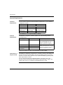
Advantys STB Configuration
Software Quick Start Guide
31002962.01
06/2005
2
Table of Contents
Safety Information . . . . . . . . . . . . . . . . . . . . . . . . . . . . . . . . . . . . 5
About the Book . . . . . . . . . . . . . . . . . . . . . . . . . . . . . . . . . . . . . . . 7
Chapter 1
Hardware and Software Requirements. . . . . . . . . . . . . . . . . . . . 9
Introduction . . . . . . . . . . . . . . . . . . . . . . . . . . . . . . . . . . . . . . . . . . . . . . . . . . . . . . 9
System Requirements . . . . . . . . . . . . . . . . . . . . . . . . . . . . . . . . . . . . . . . . . . . . . 10
How to install and remove the Advantys software. . . . . . . . . . . . . . . . . . . . . . . . 11
Chapter 2
Configuration Software Overview . . . . . . . . . . . . . . . . . . . . . . . 13
Introduction . . . . . . . . . . . . . . . . . . . . . . . . . . . . . . . . . . . . . . . . . . . . . . . . . . . . .
Introduction . . . . . . . . . . . . . . . . . . . . . . . . . . . . . . . . . . . . . . . . . . . . . . . . . . . . .
Starting the Advantys Configuration Software. . . . . . . . . . . . . . . . . . . . . . . . . . .
What Is an Island?. . . . . . . . . . . . . . . . . . . . . . . . . . . . . . . . . . . . . . . . . . . . . . . .
The Workspace . . . . . . . . . . . . . . . . . . . . . . . . . . . . . . . . . . . . . . . . . . . . . . . . . .
Island Segments . . . . . . . . . . . . . . . . . . . . . . . . . . . . . . . . . . . . . . . . . . . . . . . . .
Creating a Project with the Advantys Configuration Software. . . . . . . . . . . . . . .
Chapter 3
13
14
15
16
18
20
24
Creating an Island Bus Configuration . . . . . . . . . . . . . . . . . . . 27
Introduction . . . . . . . . . . . . . . . . . . . . . . . . . . . . . . . . . . . . . . . . . . . . . . . . . . . . .
Creating a Workspace. . . . . . . . . . . . . . . . . . . . . . . . . . . . . . . . . . . . . . . . . . . . .
The Rails . . . . . . . . . . . . . . . . . . . . . . . . . . . . . . . . . . . . . . . . . . . . . . . . . . . . . . .
Adding Modules to an Island Segment . . . . . . . . . . . . . . . . . . . . . . . . . . . . . . . .
Adding Extension Rails to the Island Configuration . . . . . . . . . . . . . . . . . . . . . .
Extending the Configuration to a Preferred Module . . . . . . . . . . . . . . . . . . . . . .
Extending the Configuration to Standard CANopen Devices . . . . . . . . . . . . . . .
Adding and Deleting Annotation to an Island . . . . . . . . . . . . . . . . . . . . . . . . . . .
Offline Protection. . . . . . . . . . . . . . . . . . . . . . . . . . . . . . . . . . . . . . . . . . . . . . . . .
Online Protection. . . . . . . . . . . . . . . . . . . . . . . . . . . . . . . . . . . . . . . . . . . . . . . . .
27
28
29
30
32
33
34
36
38
40
3
Chapter 4
Configuration Software Structure . . . . . . . . . . . . . . . . . . . . . . 41
Introduction . . . . . . . . . . . . . . . . . . . . . . . . . . . . . . . . . . . . . . . . . . . . . . . . . . . . . 41
Windows Conventions . . . . . . . . . . . . . . . . . . . . . . . . . . . . . . . . . . . . . . . . . . . . . 42
Menus . . . . . . . . . . . . . . . . . . . . . . . . . . . . . . . . . . . . . . . . . . . . . . . . . . . . . . . . . 44
Menu Commands. . . . . . . . . . . . . . . . . . . . . . . . . . . . . . . . . . . . . . . . . . . . . . . . . 46
Keyboard Navigation . . . . . . . . . . . . . . . . . . . . . . . . . . . . . . . . . . . . . . . . . . . . . . 48
Toolbars . . . . . . . . . . . . . . . . . . . . . . . . . . . . . . . . . . . . . . . . . . . . . . . . . . . . . . . . 50
Index
4
. . . . . . . . . . . . . . . . . . . . . . . . . . . . . . . . . . . . . . . . . . . . . . . 55
Safety Information
§
Important Information
NOTICE
Read these instructions carefully, and look at the equipment to become familiar with
the device before trying to install, operate, or maintain it. The following special
messages may appear throughout this documentation or on the equipment to warn
of potential hazards or to call attention to information that clarifies or simplifies a
procedure.
The addition of this symbol to a Danger or Warning safety label indicates
that an electrical hazard exists, which will result in personal injury if the
instructions are not followed.
This is the safety alert symbol. It is used to alert you to potential personal
injury hazards. Obey all safety messages that follow this symbol to avoid
possible injury or death.
DANGER
DANGER indicates an imminently hazardous situation, which, if not avoided, will
result in death, serious injury, or equipment damage.
WARNING
WARNING indicates a potentially hazardous situation, which, if not avoided, can result
in death, serious injury, or equipment damage.
CAUTION
CAUTION indicates a potentially hazardous situation, which, if not avoided, can result
in injury or equipment damage.
06/2005
5
Safety Information
PLEASE NOTE
Electrical equipment should be serviced only by qualified personnel. No responsibility is assumed by Schneider Electric for any consequences arising out of the use
of this material. This document is not intended as an instruction manual for untrained
persons.
© 2005 Schneider Electric. All Rights Reserved.
6
06/2005
About the Book
At a Glance
Document Scope
This document provides basic information and instructions for getting the Advantys
STB Configuration Software set up and operating.
Validity Note
The data and illustrations found in this book are not binding. We reserve the right to
modify our products in line with our policy of continuous product development. The
information in this document is subject to change without notice and should not be
construed as a commitment by Schneider Electric.
06/2005
7
About the Book
Related
Documents
Title of Documentation
Reference Number
The Advantys STB System Planning and Installation Guide
890USE17100
The Advantys STB System Hardware Components Reference Guide 890USE17200
The Advantys STB Profibus DP Network Interface Applications
Guide
890USE17300
The Advantys STB INTERBUS Network Interface Applications Guide 890USE17400
The Advantys STB DeviceNet Network Interface Applications Guide 890USE17500
Product Related
Warnings
The Advantys STB CANopen Network Interface Applications Guide
890USE17600
The Advantys STB Ethernet TCP/IP Modbus Network Interface
Applications Guide
890USE17700
The Advantys STB Modbus Plus Network Interface Applications
Guide
890USE17800
The Advantys STB Fipio Network Interface Applications Guide
890USE17900
The Advantys STB Reflex Actions Reference Guide
890USE18300
Schneider Electric assumes no responsibility for any errors that may appear in this
document. If you have any suggestions for improvements or amendments or have
found errors in this publication, please notify us.
All pertinent state, regional, and local safety regulations must be observed when
installing and using this product. For reasons of safety and to ensure compliance
with documented system data, only the manufacturer should perform repairs to
components.
When controllers are used for applications with technical safety requirements,
please follow the relevant instructions.
Failure to use Schneider Electric software or approved software with our hardware
products may result in injury, harm, or improper operating results.
Failure to observe this product related warning can result in injury or equipment
damage.
User Comments
8
We welcome your comments about this document. You can reach us by e-mail at
[email protected]
06/2005
Hardware and Software
Requirements
1
Introduction
Overview
The Advantys configuration software is designed to run on various Microsoft
Windows-based operating systems. This chapter describes your computer system
requirements. It also provides instructions for installing and uninstalling the
software.
What's in this
Chapter?
This chapter contains the following topics:
06/2005
Topic
Page
System Requirements
10
How to install and remove the Advantys software
11
9
Requirements
System Requirements
Hardware
Requirements
Your PC needs to meet the following hardware requirements to run the Advantys
configuration software:
Requirement
Minimum
computer
Pentium III or equivalent
Recommended
RAM
128 MB
256 MB
free hard drive
space
120 MB
150 MB
monitor display
256 color VGA
1024 x 768 resolution
A CD-ROM drive is the required installation medium.
Software
Requirements
The Advantys configuration software requires one of the following software
operating systems:
Operating System
Edition/Service Pack
Special Considerations
Microsoft Windows 98
second edition (SE)
For Windows 98 (SE), we recommend
that you limit physical memory size to a
maximum of 256 MB and set up
contiguous permanent swap files.
Windows NT 4.0
service pack 6 or above
Windows 2000
service pack 1 or above
Windows XP
Professional
service pack 1 or above
For Windows NT, Windows 2000 or
Windows XP Porfessional, you need
administration privileges to install the
Advantys configuration software.
The browser needs to be Microsoft Internet Explorer 4.01 or higher.
Connection to a
Physical Island
The Advantys configuration software runs on a PC that connects to the CFG port on
the network interface module (NIM) of the physical Advantys island. You need to
make the connection with a special 2 m (6.2 ft) STB XCA 4002 programming cable,
which ships with the software.
For more information about the required hardware connections, refer to the
Advantys STB System Planning and Installation Guide (890 USE 171 00) or the
CFG port discussion in your Advantys STB NIM applications guide.
10
06/2005
Requirements
How to install and remove the Advantys software
Before You Start
Before you install the Advantys configuration software:
z
z
Installation
Remove any previous version of the Advantys configuration software.
Close all Windows applications and virus-protection software.
To install the Advantys configuration software:
Step
06/2005
Action
Result
1
Insert the Advantys CD in your PC’s CD- If the AUTORUN function is activated,
ROM drive.
the installation will start automatically.
2
If the installation does not start
automatically, double-click [CD-ROM
drive:]\start.exe.
The Language Selection screen
appears.
3
Choose a language and click Next.
The Action Selection screen
appears.
4
Select the action you want to perform.
Select Install Advantys
Configuration Software to install
the software.
The Installation Wizard screen
appears.
5
Enter Next to start the installation.
The License Agreement screen
appears.
6
Accept the license agreement and enter The Readme Information screen
Next.
appears.
7
Enter Next to continue the installation.
The Catalog Selection screen
appears.
8
Select the catalog(s) and enter Next to
continue.
The User Information screen
appears.
9
Enter your user information and the
following apllication settings. Enter
Next to continue the installation.
The Destination Folder screen
appears.
10
Browse the destination folder or use the The Select Installation Type
standard folder. Enter Next to continue screen appears.
the installation.
11
Select the type of installation you want to The last screen appears.
use. Please select Typical for a
standard installation. Enter Next to
continue the installation.
11
Requirements
Step
Removal
Action
Result
12
Enter Finish to start the installation of The installation status appears.
the Advantys Configuration Software on
your computer.
13
To register the software, click Yes. To
run the software without registering it,
click No.
An unregistered software package will
run for 21 days, then stop running. You
will need to uninstall the expired
software before installing a new
version. The new installation must be
registered before it will work.
14
Follow the remaining on-screen
installation instructions.
Once the software has been installed,
an icon appears on your desktop,
which you can double-click to start the
software:
To remove the Advantys configuration software from your computer, chose the
following path:
Start →Settings →Control Panel →Add/Remove Programs
12
06/2005
Configuration Software Overview
2
Introduction
Overview
This chapter provides an overview of the basic components of the Advantys
configuration software.
What's in this
Chapter?
This chapter contains the following topics:
06/2005
Topic
Page
Introduction
14
Starting the Advantys Configuration Software
15
What Is an Island?
16
The Workspace
18
Island Segments
20
Creating a Project with the Advantys Configuration Software
24
13
Configuration Software Overview
Introduction
Overview
The Advantys configuration software supports the Advantys STB distributed I/O
system, an open, modular system designed for the machine industry, with a
migration path to the process industry.
The software is an optional feature of the system that can be used to:
Create, modify and save the configuration descriptions of all the physical devices
on an island. These tasks are performed mainly in offline mode, although some
modifications may be done online.
z Monitor island performance, adjust data values, and build a binary file describing
the Island configuration.
z
Configuration
Check
The Advantys configuration software checks for correctness (numeric limitations on
modules and I/O points, compatibility between power supply modules and I/O
modules, etc.) whenever possible during the editing process. Otherwise, these
checks are made when a complete project build is performed.
The software provides features that help you plan:
Logic and field power consumption
z I/O image area consumption
z
Editors
The software features three main editors:
Island Editor, which provides a graphical display of the island segment(s) and
the order in which the modules are installed.
z I/O Module Editor, where you can customize the operating parameters of the
individual I/O modules.
z Reflex Editor, where you can program Reflex actions and map their results to
individual output modules on the Island.
z
Software
Outputs
A list of the modules available for your Island configuration is displayed in the
Catalog browser of the Advantys configuration software. Use this browser to select
and install modules in the Island Editor.
The configuration software provides three major outputs:
A device description file. You may generate this device description file in several
different formats depending on the intended usage and the field bus format.
z A binary image of the configuration suitable for downloading into the Island.
z A printout of project documentation.
z
14
06/2005
Configuration Software Overview
Starting the Advantys Configuration Software
In the Windows
Environment
From the
Command Line
To launch the Advantys configuration software in the Windows environment:
Step
Action
1
Click the Start button.
2
From the Programs option, select Schneider Electric, followed by Advantys,
and Advantys once again.
3
From the popup window select the type of physical island you want to configure.
3
Select the language you want to use.
4
Click OK.
To start the Advantys configuration software from a command line editor:
Step
Action
1
Open the command line editor.
2
At command prompt, type advantys.exe -w followed by a path to the workspace.
For example:
"C:\Program Files\Schneider Electric\Advantys\Advantys.exe" -w
"C:\Program Files\Schneider Electric\Advantys\projects\test\test.aiw"
Note: You can omit the -w and it opens with the previous workspace as if launched
in windows.
3
Press Enter.
3
From the popup window select the type of physical island you want to configure.
4
Select the language you want to use.
5
Click OK.
If you enter a wrong argument as a command parameter, a warning message is
displayed with suggested valid arguments.
06/2005
15
Configuration Software Overview
What Is an Island?
Overview
Before we describe the different capabilities available in the Advantys configuration
software, let’s distinguish between a physical island in the real world of your
application and a logical island in the context of the software.
A Physical Island
An island is an assembly of distributed I/O, power distribution and island bus
communication/extension modules that function together as one node on a fieldbus.
An island contains up to 32 I/O modules plus a NIM, one or more power distribution
modules PDMs, and optionally some modules that let you extend the bus to multiple
segments (or rails) of Advantys STB I/O, to Advantys STB preferred modules, and
to standard CANopen devices.
The following illustration shows an example of a segment on a physical island:
1
2
3
4
5
6
Module (1) is the NIM, followed by a PDM (2) and a voltage group of I/O modules
(3). A second PDM follows this I/O group. The second PDM (4) supports another
group of I/O modules (5) that require a different field power voltage or additional
current. The last device on the segment is an EOS module (6), which allows you to
extend the physical island to another segment of Advantys I/O modules or to a
preferred module.
16
06/2005
Configuration Software Overview
A Logical Island
The Advantys configuration software lets you model a physical island so that it can
be tested against our design rules and customized to meet your application
requirements. We call the software model the logical island (see also .
The logical island is a file in the software program with a .isl extension. It contains a
description of the physical island—all the modules on the island and all the operating
parameters associated with each module that may be defined in software.
As you develop a logical island, the software will provide warnings about any
mistakes you have made in the model, and usually it will prevent you from creating
an invalid configuration. For example, it prevents you from placing a DC module in
a location where it would receive AC field power (and vice versa).
06/2005
17
Configuration Software Overview
The Workspace
Overview
The workspace is a project environment in the Advantys configuration software. The
workspace is where you design a logical island configuration. Within the workspace,
you can create a new configuration and download it to the physical island. You can
also upload configuration data from a physical island to a logical island in the
workspace (see also ).
A workspace is saved as a file with an .aiw extension.
Relationship of
the Workspace to
an Island
One or more logical islands can be created and managed in a workspace, up to a
maximum of 10 islands. The configuration data associated with each island is stored
in its own .isl file in the workspace.
Customizing
Your Workspace
You can customize your workspace settings by selecting Settings from the Options
pull-down menu. These settings include:
z
z
z
The interface language (English, French, German, Spanish or Italian).
Foreground and background colors.
The default directory path.
If you have more than one workspace on your computer, you can define different
settings for different workspaces.
18
06/2005
Configuration Software Overview
A Workspace
Screen
A workspace screen consists of the following areas:
Advantys - [Aircond_In - Locked]
File Edit View Island Online Options Window Help
1
Catalog Browser
Workspace
i
workspace1
i Island1
3
i Segment1
STBNDP2212 - V
STBPDT3100 - V 1.0
STBDDO3200 - V 0.45
2
STBDDO3600
1 - V 0.45
STBDDO3410 - V 0.45
STBAVI1270 - V 0.45
STBAVO1250 - V 0.45
STBXBE1200 - V 1.0
Aircond_In...
Aircond_In...
i
4
Catalog
Networking
Power
Digital Input
Digital Output
Analog Input
Special-purpo
Accessories
Preferred
CAN Enhanced CA
5
Island 2 ...
Island 2 ...
6
Offline
1
2
3
4
5
6
Toolbars
Workspace Browser
Island Editor
DIN Rail
Catalog Browser
Log Window
These areas may be hidden, enlarged, reduced, moved or docked on the workspace
screen. If you modify the layout of a workspace screen, the layout definition is saved.
Each time you reopen that workspace, the screen appears with the layout that you
used the last time you saved the workspace.
The illustration above shows the default locations of each of the six workspace
areas. The functions of these area will be described in more detail over the next few
pages.
06/2005
19
Configuration Software Overview
Island Segments
Primary Segment
Each island must include at least one segment, called the primary segment. The
primary segment is always the first segment in the island configuration. It is where
the network interface module (NIM) resides.
Modules in the
Primary Segment
The NIM is always located in the first (leftmost) slot in the primary segment. The
power supply built into the NIM converts 24 VDC into a 5 V logic power signal that
supports all other modules in the primary segment.
The NIM is immediately followed by a power distribution module (PDM), which will
distribute field power to the input and output modules on your Island. Depending on
the type of I/O modules in the segment, you will use an STB PDT 310x PDM (to
distribute 24 VDC), an STB PDT 210x PDM (to distribute 115 or 230 VAC) or some
combination of the two PDM types.
The power supply in the NIM supports 1.2 A of current to be drawn by the I/O
modules in the segments.
Auxiliary Power
Supply
The STB CPS 2111 auxiliary power supply provides 5 VDC logic power to the
modules installed to its right in an Advantys STB island segment. It works together
with the NIM (in the primary segment) or with a BOS module (in an extension
segment) to provide logic power when the I/O modules in the segment draw current
in excess of 1.2 A.
The module convertd 24 VDC from an external power source to an isolated 5 VDC
of logic power, providing up to 1.2 A of current to the modules to its right.
20
06/2005
Configuration Software Overview
Last Device in a
Primary Segment
Each Advantys system must be terminated at the last module. If the island
comprises only the primary segment, use the STB XMP 1100 termination plate as
the last module in this segment. If the island is extended to either another segment
of Advantys STB modules or to a preferred module, do not use the termination plate
at the end of the primary segment.
The following table describes different ways to end a primary segment, depending
on your requirements.
If ...
... then
the island bus comprises just one
segment with no extensions
terminate the primary segment with an STB XMP
1100 termination plate
the island bus is extended to another
segment of Advantys STB I/O modules
do not use a termination plate in the primary
segment; install an STB XBA 2400 base to hold an
STB XBE 1000 EOS module at the end of the
segment
the island is extended to a preferred
module
install an STB XBA 2400 base to hold an STB XBE
1000 EOS module at the end of the segment
the island is extended to an exhanced or install an STB XBA 2000 base to hold an STB XBE
a standard CANopen device
2100 CANopen extension module at the end of the
segment, followed by a STB XMP 1100
termination plate
Island Bus
Extensions
06/2005
There are several reasons why you might want to extend your island configuration
beyond the primary segment:
z To position the I/O modules as close as possible to the sensors and actuators
they control
z To extend the Island bus to devices other than Advantys STB I/O modules
(preferred modules and/or enhanced CANopen devices and/or standard
CANopen devices)
21
Configuration Software Overview
Extending the
Island to
Extension
Segments of STB
I/O Modules
When you extend the island bus to additional segments of STB I/O, these segments
are called extension segments. An island bus may support up to six extension
segments of STB I/O modules. Extension segments must be preceded by one
primary segment.
The first (leftmost) module in each extension segment is an STB XBE 1200
beginning-of-segment (BOS) module. It is followed by a PDM and one or more STB
I/O module(s). The BOS has a built-in power supply like the one used in the NIM. It
provides 1.2 A of current to support the STB I/O modules in its extension segment.
Aux power supply can provide additional logic current if necessary.
The BOS is connected to the previous segment (or to a preferred module) by an
Island bus extension cable. The cable and the BOS module extend the island's
communication bus and auto-addressing line to the new segment.
Just as with the primary segment, the last device in an extension segment may be
either:
z An STB XMP 1100 termination plate, if this is the last segment of the Island
z An STB XBE 1000 EOS module, if it is immediately followed by another extension
segment or a preferred module
z An STB XBE 2100 CANopen extension module, if it is immediately followed by a
STB SMP 1100 termination plate
In the Advantys configuration software, each segment is shown on a separate DIN
rail. In a real physical installation, more than one segment may be placed on the
same DIN rail.
Extending the
Island to
Preferred
Modules
You may also extend the island bus to one or more preferred module(s). In most
respects, the island bus handles them just as other STB I/O modules. There are,
however, two key differences:
z A preferred module is not designed in the Advantys STB form factor and does not
fit into one of the standard base units. It therefore does not reside in a segment.
z It may require its own power supply.
A preferred module must have an input connection to receive an island bus
extension cable from the upstream island module. It is designed with an extension
cable output connection that allows it to send island bus signals to a downstream
module or segment. It also has the ability to terminate the island bus in the event
that it is the island's last module.
An island can support as many as 31 preferred modules. (The primary segment
must include at least one Advantys STB I/O module.) You may use island bus
extension cables to daisy-chain multiple preferred modules together.
22
06/2005
Configuration Software Overview
Extending the
Island to
enhanced or
standard
CANopen
Modules
You may also extend the island bus to one or more CANopen devices. The island
bus supports up to 12 CANopen devices. This type of bus extension requires a
special STB XBE 2100 CANopen extension module as the last module of the
segment preceding the first CANopen device.
CANopen devices must always be the last devices on the island bus.
CANopen devices must be addressed manually, usually via a set of address
switches built onto the devices. The baud rate has to be set to 500 kBaud. The
Module Editor for the NIM also offers the possibility to set up the maximum node
ID value to be used on a CANopen extension, through the Properties tab. Any
manually set address switch must match the automatically assigned node ID. The
address assignement for the CANopen modules starts with this value, counting
downwards to avoid any overlap with addresses automatically assigned to the
Advantys STB modules. The default value is 32; however, it may be modified in
order to enforce the use of lower node IDs for CANopen devices. Indeed, some of
these devices may have a restricted configurable address range.
Whenever a standard CANopen device is part of the island bus, the bus must be
configured to operate at 500 kBaud. The default baud rate is 800 kBaud, so you
must change it with the Advantys configuration software. To change the baud rate
select from the Island menu .
When you are using standard CANopen devices, do not push the RST button on the
NIM. The RST button will cause the baud rate to be set to 800 kBaud, and the island
bus will not operate properly.
Maximum Length
of the Island Bus
06/2005
The total length of the island bus, from the NIM to the last device, must not exceed
15 m (49.2 ft). This length includes the sum of the lengths of all bus extension cables
and CANopen cables connecting devices as well as the widths of the hardware
modules themselves.
23
Configuration Software Overview
Creating a Project with the Advantys Configuration Software
Overview
The Advantys configuration software provides a set of Windows-based tools that
enable you to plan, model, customize, and test island bus designs and to download
custom configurations to physical islands.
Advantages of
Using the
Software
All the Advantys STB I/O modules have factory-default parameter settings that allow
them to be operational directly out of the box. If you want to customize your island’s
operational capabilities, however, you need to use the Advantys configuration
software.
The software lets you:
z
z
z
z
z
z
24
customize the operating parameters of the I/O modules
create and implement reflex actions
optimize island performance by assigning priority to certain modules
designate certain application-critical modules as mandatory
add preferred modules and/or standard CANopen devices to the island
configuration
validate that your island configuration adheres to Advantys STB design
guidelines
06/2005
Configuration Software Overview
Project Work
Flow
The following flowchart describes the work flow associated with a valid island
configuration:
Create a
workspace
Create an
Island
Add modules
from catalog
Add another
segment?
Add EOS/BOS
modules
YES
NO
NO
Add preferred
module(s)?
YES
Add EOS module
Add preferred
module
NO
Add CANopen
device(s)?
Add another
preferred module?
YES
YES
Add CANopen
extension
module
Terminate last
island segment
Add CANopen
device(s)
NO
Terminate island
YES
Create another
island?
NO
End
06/2005
25
Configuration Software Overview
26
06/2005
Creating an Island Bus
Configuration
3
Introduction
Overview
This chapter describes how a logical island configuration can be created in an active
workspace.
What's in this
Chapter?
This chapter contains the following topics:
06/2005
Topic
Page
Creating a Workspace
28
The Rails
29
Adding Modules to an Island Segment
30
Adding Extension Rails to the Island Configuration
32
Extending the Configuration to a Preferred Module
33
Extending the Configuration to Standard CANopen Devices
34
Adding and Deleting Annotation to an Island
36
Offline Protection
38
Online Protection
40
27
Creating an Island Configuration
Creating a Workspace
Overview
Before you can create a .isl file for a logical island, you need to open an existing
workspace or create a new one. In the Advantys configuration software, an island
can exist only inside a workspace.
The first time you start the configuration software, you must first create a workspace.
When you create the workspace, it automatically creates a new island inside it. You
can add additional islands to the workspace. A workspace can contain up to 10
islands.
Creating a
Workspace
28
The following table shows how to create a new workspace:
Step
Action
Result
1
Select New Workspace from the
File menu.
The New Workspace dialog box displays.
2
In the Workspace File field of the
dialog, enter a name for the
workspace.
A workspace name can be up to 50
characters long and can comprise
alphanumeric plus space, "_" and "-"
keyboard characters.
3
In the Island File field of the dialog,
enter a name for the island.
An island file name can be up to 50
characters long and can comprise alphanumerics, spaces and other keyboard
characters.
4
Click OK.
A new workspace screen appears with the
new island open in it. All that appears in the
island editor is an empty DIN rail.
06/2005
Creating an Island Configuration
The Rails
Overview
An empty rail appears in the island editor as soon as a new island is created:
This rail will support the Advantys STB modules in the primary segment of the new
island bus configuration. All the modules in the primary segment of the island (the
NIM, PDMs, Aux power supply, I/O modules, extension modules or termination
plate) will be inserted on this default rail.
Deleting and
Adding the
Primary Rail
If you delete the primary rail from the island editor and then want to replace it, use
the Add Rail command from the Island menu. You must have the primary rail to
configure a logical island.
Adding More
Rails
Each segment in a logical island appears on its own rail. The maximum number of
rails in an island configuration is seven - one for the primary segment and up to six
for extension segments.
In the Advantys configuration software, a segment is referred to a rail.
Preferred modules (See Extending the Configuration to a Preferred Module, p. 33)
and CANopen devices (See Extending the Configuration to Standard CANopen
Devices, p. 34) do not appear on separate rails in the island editor. They appear
beside or below the rail from which they are extended.
06/2005
29
Creating an Island Configuration
Adding Modules to an Island Segment
Overview
There are three ways to add modules to a rail:
z
z
z
drag-and-drop function
double-click on the module
select the module and press Enter
If you try to add a module on the rail in an invalid location, a warning message
appears and the software does not allow the module to be dropped in that location.
Drag-and-Drop
Method
To add a module to a rail using the drag-and-drop method:
Step
Action
Result
1
Select the module name in the
catalog browser .
The module name is highlighted.
2
Drag it to the desired location on
the rail in the island editor.
As the module is dragged across the
workspace, the
icon displays.
When the module crosses over the rail, one of
the following icons appears:
z
z
3
Double-Click
Method
indicating an invalid position
A graphical version of the module drops in the
location on the rail.
The double-click method is usually the quickest way to add a module to the
configuration:
z
z
30
Release the mouse button on a
valid location.
indicating a valid position
If you want to add a module to the end of the last rail, simply double-click on the
module name in the catalog browser . A graphical version of the module appears
at the end of the rail.
If you want to place a module between two modules that are already on the
island, select the leftmost of the two existing modules in the island editor, then
double-click on the new module name in the catalog browser. A graphical version
of the new module appears between the two existing modules on the rail.
06/2005
Creating an Island Configuration
Enter Key
Method
The Enter key method is similar to the double-click method:
z
z
06/2005
If you want to add a module to the end of the last rail, single-click on the module
name in the catalog browser , then push Enter. A graphical version of the module
appears at the end of the rail.
If you want to place a module between two modules that are already on the
island, select the leftmost of the two existing modules in the island editor, then
select the new module name in the catalog browser and push Enter. A graphical
version of the new module appears between the two existing modules on the rail.
31
Creating an Island Configuration
Adding Extension Rails to the Island Configuration
Procedure
You can extend the island configuration over longer distances by adding extension
rails:
Step
Action
1
If there is a terminator plate at the end of the last existing rail, remove it. Also
remove the XBE2100 module, if there is one, and the modules attached to it.
2
Pick an EOS module from the catalog browser and drop it in the island editor at
the end of the last rail.
3
Double-click on a BOS module in the catalog browser.
A new rail will appear in the island editor below the existing one. The BOS
module (3) is the first module on the new rail. An extension cable (2) connects
the EOS module (1) and the BOS module.:
1
2
3
4
Pick a PDM from the catalog browser and drop it in the island editor next to the
BOS module. Add Auxillarry power supplies if necessary.
5
Pick the appropriate I/O modules from the catalog browser and drop them in
voltage group(s) after the PDM(s).
6
Pick either a terminator plate or another extension module (either an EOS or a
CANopen extension module) and drop it at the end of the new rail.
Note: An island can support up to seven rails. The primary is required, and up to
six extension rails are optional.
32
06/2005
Creating an Island Configuration
Extending the Configuration to a Preferred Module
Procedure
To extend an island configuration from a rail to a preferred module:
Step
Action
1
If there is a terminator plate at the end of the last existing rail in the island editor,
remove it.
2
Pick an EOS module from the catalog browser and drop it in the island editor at
the end of the rail.
3
Double-click on a preferred module in the catalog browser.
The preferred module (3) appears in the island editor beside the rail. An
extension cable (2) connects the EOS module (1) and the preferred module.
2
1
3
4
If you want to add another preferred module, repeat step 3. Each additional
module is placed to the right of the previous module, with a cable connection
between them.
If you want to extend to a new Advantys I/O rail, go to step 5.
If you want the preferred module to be the last module on the island, go to step 6.
5
Double-click on a BOS module in the catalog browser.
A new rail will appear below the existing one. The BOS module is the first
module on the new rail. An extension cable connects the preferred module and
BOS module (See Adding Extension Rails to the Island Configuration, p. 32).
6
Apply 120 Ω termination to the physical preferred module.
Note: There is no graphical element in the software to indicate termination on a
preferred module. You must provide this termination on the physical module.
06/2005
33
Creating an Island Configuration
Extending the Configuration to Standard CANopen Devices
Procedure
An Advantys STB island does not auto-address standard CANopen devices. If your
application includes standard CANopen devices, they must be installed as the last
devices on the island. You must set their island addresses manually on the devices.
Install all your auto-addressable modules (Advantys I/O and preferred modules)
first.
To extend the configuration from a rail to standard CANopen devices:
Step
Action
1a
If there is a terminator plate at the end of the last rail in the island editor, pick a
CANopen extension module from the catalog browser and drop it in front of the
termination plate.
1b
If there is not a terminator plate at the end of the last rail, pick an CANopen
extension module from the catalog browser and drop it in the last position on
the rail. Then pick a termination plate from the catalog browser and drop it after
the CANopen extension module.
2
Pick a CANopen device from the catalog browser . The device appears in the
island editor below the CANopen extension module and off the rail (3). An
extension cable (2) connects the CANopen extension module (1) and the
CANopen device (3).
1
3
3
34
2
2
If you want to add another CANopen device, repeat step 2. Each additional
device is placed to the right of the previous device and is connected by a
CANopen extension cable.
06/2005
Creating an Island Configuration
Step
4
Action
If you do not want to add more standard CANopen devices to the configuration,
apply 120 Ω termination to the CANopen device.
Note: There is no graphical element in the software to indicate termination on a
standard CANopen device. You must provide this termination on the physical
device.
06/2005
35
Creating an Island Configuration
Adding and Deleting Annotation to an Island
Adding
Annotation
Text comments can be placed in the island editor with the annotation feature. There
are three ways to annotate a logical island:
z
z
z
Resizing the
Annotation Box
click the
button in the Island toolbar
right-click on a location in the island editor, then select Add Annotation from the
menu
select Add Annotation from the Island menu
The annotation box can be resized to accommodate any amount of text.
The following table shows how to resize an annotation box:
Step
1
Action
Select the annotation box. When it is selected, handles appear on the corners
and sides of the box.
2
Position the mouse cursor over a handle until the cursor changes to
3
Moving the
Annotation Box
An annotation box can be moved anywhere within the Island Editor.
The following table shows how to move an annotation box:
Step
Deleting Text
from an
Annotation Box
36
.
Drag the handle until you achieve the desired size.
Action
1
Resize the annotation box slightly, as described above. (The color of the
handles on the box should be green.)
2
Drag the selected box to the desired location in the Island Editor.
The following table shows how to delete text from an annotation box:
Step
Action
1
Select the annotation box.
2
Press Enter.
06/2005
Creating an Island Configuration
Retrieving Text
for an Annotation
Box
The following table shows how to retrieve text that has just been deleted from an
annotation box:
Step
1
Action
Select the empty annotation box.
2
Click the
Deleting an
Annotation Box
06/2005
button.
The following table shows how to delete an annotation box along and its contents:
Step
Action
1
Select the annotation box.
2
From the Island menu, click Delete Annotation.
37
Creating an Island Configuration
Offline Protection
Overview
Whenever you open an existing island (.isl) file, it comes up locked. When a file is
locked, you can monitor it in the workspace screen, but you cannot edit it. Editing is
possible only when the file is unlocked. Optionally, you can apply password
protection to the offline lock. If you apply a password, you will not be able to unlock
the file without first entering the password.
Applying a
Password to the
Lock
To apply a password to the lock a .isl file:
Step
Action
1
While the new .isl file is active in the workspace, click
appears asking you if you want to set a password.
. A message
2
Click Yes.
3
Type a password, then retype it to confirm.
4
Click OK.
5
A message appears prompting you to save the file with the new password.
Click OK.
The password must be an alphanumeric string between 1 and 32 characters long.
An empty password is not valid.
Changing the
Lock Password
To change the password on the lock:
Step
Action
1
While the .isl file is active in the workspace, click
asking you if you want to change the password.
38
. A message appears
2
Click Yes.
3
Enter the old password, then the new one, and then confirm the new password.
4
Click OK.
5
A message appears prompting you to save the file with the new password.
Click OK.
06/2005
Creating an Island Configuration
Unlocking
After a password has been applied to a .isl file, you need to know the password to
unlock and edit the file when you reopen it. To unlock a password-protected .isl file:
Step
Action
1
While the .isl file is active in the workspace, click
06/2005
2
Enter the password.
3
Click OK.
.
39
Creating an Island Configuration
Online Protection
Overview
An online protection capability is available to prevent unauthorized changes or
overwrites to the configuration data in the physical island. When online protection is
enabled, the RST button on the NIM is disabled and data on the removable memory
card is ignored.
You will be asked to apply a password to the online protection. When a password is
applied, a user needs to know the password in order to remove the protection
feature or get into (or out of) temporary test mode.
Note: Be sure to record the password. If you forget the password, you cannot use
the RST button to reset the default configuration parameters or the removable
memory card to load a new configuration. Also, you cannot change modes on the
physical island (test mode/run mode) without the password while online protection
is enabled.
The Online
Protection
Feature
The protection feature is available only in online mode (when the active .isl file in the
Advantys configuration software is connected to a physical island).
To enable online protection for the physical island:
Step
Action
1
From the Online menu, click Protect.
2
Enter a password.
3
Click OK.
The Protect command toggles the feature on and off. When protection is applied, a
check mark appears in the box next to the command in the pull-down menu.
The Password
The password must be an alphanumeric string between 0 and 6 characters long. An
empty password is valid.
When protection is activated, you will be queried for a password if you try to execute
a command online. If you are not using a password, simply click OK when the
password dialog appears.
Unprotecting
40
To disable online protection, click Online →Protect again to toggle the feature off.
When online protection is not applied, there is no check mark next to the command
in the pull-down menu.
06/2005
Configuration Software Structure
4
Introduction
Overview
This chapter provides a description of the basic user interface functions like
navigation and working with menu items. The available menus and all contained
items are presented as a reference.
What's in this
Chapter?
This chapter contains the following topics:
Topic
Windows Conventions
06/2005
Page
42
Menus
44
Menu Commands
46
Keyboard Navigation
48
Toolbars
50
41
Configuration Software Structure
Windows Conventions
Overview
There are three standard Windows conventions available for moving objects in the
Advantys configuration software workspace:
z Drag-and-Drop
z Dock
z Float
Drag-and-Drop
You can drag modules from the Catalog Browser and drop them into the Island
Editor. The following table shows hot to Drag-and-Drop a module:
Step
Action
Indication
1
Select a desired module in the
Catalog Browser.
-
2
Drag the selected module toward the The cursor should look like this:
DIN rail in the Island Editor.
3
Drag the module into position on the The
DIN rail.
cursor should appear, indicating that the
module location is valid.
If the
cursor appears, the module location is
invalid. It violates the island's connectivity
rules.
Note: Annotation boxes can be moved in the Island Editor also via Drag-and-Drop.
Dock
42
A standard Windows docking operation lets you drag a window from its original
position in the workspace to any corner of the application area. Docking can be
applied to the Workspace Browser, the Catalog Browser and the toolbars.
06/2005
Configuration Software Structure
Float
06/2005
A standard Windows float operation lets you drag the window from its original
position in the workspace to any part of the application area. Floating can be applied
to the Workspace Browser, the Catalog Browser and the toolbars.
43
Configuration Software Structure
Menus
Overview
There are 3 types of menus:
Main or pulldown menus
z Submenus
z Shortcut or popup menus
z
Main or Pulldown
Menus
The titles of the individual menus are displayed in the menu bar. The individual menu
commands are listed in the pulldown menus. A pulldown menu is opened by leftclicking on the title of the menu or by pressing Alt+selected letter (underlined
letter).
The following figure shows the menu bar with a pulldown menu:
Advantys - [Island1 - Locked]
File Edit View Island Online Options Window
Workspace Browser
Ctrl+W
Catalog Browser
Ctrl+T
Log Window
Ctrl+L
Tool Bars
Status Bar
Zoom
Submenus
The title of a submenu is a menu command of the menu above it. The individual
menu commands for the submenu are listed in a pulldown menu. Menu commands
which contain a submenu can be recognized by an arrow icon.
The following figure shows a submenu:
Advantys - [Island1 - Locked]
File Edit View Island Online Options Window Help
Workspace Browser
Ctrl+W
Catalog Browser
Ctrl+T
Log Window
Ctrl+L
Tool Bars
Status Bar
Zoom
44
100%
75%
50%
25%
06/2005
Configuration Software Structure
Shortcut or
popup menus
Shortcut menus are menus which contain menu commands specially for the
selected object.
You can open a shortcut menu by clicking on the object (right mouse button) or
selecting the object and confirming with Shift+F10 or press the context sensitive
key.
Shortcut menus can also be called if several objects are selected. In this case, the
menu only contains the menu commands which are valid for all objects.
The following figure shows an object with shortcut menu:
Workspace Browser
i
workspace1
i Island1
i Rail1
STBNIB2212 - V 0.02
Cut
Copy
Paste
Delete
Module Editor ...
06/2005
45
Configuration Software Structure
Menu Commands
Introduction
Menu commands are used to execute commands or to call dialog boxes.
The following figure shows an example of a menu with menu commands:
Advantys - [ISLE_1 - Locked]
File
View Island Online Options Window Help
New Workspace ...
Ctrl+N
Open Workspace ...
Ctrl+O
Save Workspace
Copy Workspace To ...
Close Workspace
Add New Island ...
Add Existing Island ...
Ctrl+A
Save ISLE_1
Ctrl+S
Copy ISLE_1 To ...
Close ISLE_1
Close ISLE_1
Remove ISLE_1
Print ...
Ctrl+P
Print Setup ...
Import ...
Export ISLE_1 ...
1 D:\P...\Power_Distrib_2\PWR_3.aiw
2 D:\P...\Workspace1\Workspace1.aiw
3 D:\A...\Projects\Paint_1\UPLD.aiw
4 D:\...\SCRS_Project\SCRS_Project.aiw
Exit
46
06/2005
Configuration Software Structure
Keyboard
Shortcuts or
Mnemonics
Keyboard shortcuts (underlined letters) in menu commands allow you to select
menu commands using the keyboard. A main menu (menu title) and subsequently
a menu command can be selected by holding down Alt and simultaneously entering
the underlined letter in the menu title and then the underlined letter of the menu
command.
For example, you want to use the File menu, Save Workspace menu command,
you must press the Alt+F to open the menu, followed by Alt+V to execute the menu
command.
Dimmed Menu
Command
If a menu command is not available it is dimmed. One or more other commands may
need to be executed before the desired menu command can be executed.
Decimals (...)
after the Menu
Command
On execution of this menu command a dialog box is opened with options, which
must be selected before execution.
Check Mark
before the Menu
Command
The menu command is active. If the menu command is selected the check mark
disappears and the menu command is inactive. The check mark is mostly used to
identify active modes (e.g. Island is protected etc.).
Shortcut Keys
Shortcut keys (e.g. F1) or key combinations (e.g. Ctrl+N) can be used for executing
the menu commands. You can select the menu command using this shortcut key or
a key combination without having to open the menu. For example, Ctrl+S can be
pressed to perform the Save menu command.
06/2005
47
Configuration Software Structure
Keyboard Navigation
Overview
The following tables describe the possibility to access certain functions directly with
keyboard shortcuts.
Global valid Key
Combinations
The following shortcuts are available throughout the Advantys configuration
software:
Key
Combinations
inside the
Browsers
48
Function
Key Combination
Open Workspace
Ctrl+O
Add existing Island
Ctrl+A
Save Island
Ctrl+S
Print
Ctrl+P
Undo
Ctrl+Z
Redo
Ctrl+Y
Cut
Ctrl+X
Copy
Ctrl+C
Delete
Del
Toggle Workspace Browser
Ctrl+W
Toggle Catalog Browser
Ctrl+T
Toggle Log Window
Ctrl+L
Delete Annotation
Ctrl+D
Help
F1
What's This?
Shift+F1
The following shortcuts are available in the Workspace Browser and Catalog
Browser:
Function
Key Combination
Expand/reduce the object trees
Space
Move down in the object tree and expands
reduced elements
Cursor right
Move up in the object tree and reduces
expanded elements
Cursor left
Move up/down in the object tree
Cursor up/down
06/2005
Configuration Software Structure
Key
Combinations
inside the Island
Editor
The following shortcuts are available in the Island Editor:
Function
Key Combination
Change between windows of different islands Ctrl+Tab
Ctrl+F6
Shift the focus to the next module on the right Cursor right
Shift the focus to the previous module on the
left
Cursor left
Change the status of a selected annotation
box
Esc
Select next object (segment, NIM, annotation) Tab
in the Island Editor
06/2005
49
Configuration Software Structure
Toolbars
Introduction
Toolbars display a collection of easy-to-use button images and/or menus that initiate
different operations in Advantys Configuration Software. Several icons are docked
in form of independent toolbars on top of the screen.
Advantys Configuration Software provides four toolbars:
Standard, p. 51
z Edit, p. 52
z View, p. 53
z Island, p. 54
z
50
06/2005
Configuration Software Structure
Standard
The Standard toolbar comprises 11 icon buttons:
Standard
You can move, dock and/or float this toolbar to other locations in the workspace. You
may also hide the toolbar by right-clicking in the toolbar and unchecking the
Standard option.
The Standard icon buttons perform following tasks:
Icon
Task
Invokes a dialog box where you can open an existing workspace.
Invokes a dialog box where you can save the currently open workspace and/or
Islands.
Invokes a dialog box where you can create a new Island in the open workspace.
Invokes a dialog box where you can add an existing Island to the open workspace.
Invokes a dialog box where you can select any of the items to be printed.
Invokes a dialog box where you can connect the software to the physical Island.
Disconnects the software from the physical Island.
In Online mode, invokes a dialog box where you can put the physical Island in Run
mode.
In Online mode, invokes a dialog box where you can stop the physical Island.
Invokes a table of contents for the Advantys help system.
Turns the cursor into a question mark so that you can invoke What's This? help
on a selected item in the workspace.
Back to top (See Introduction, p. 50)
06/2005
51
Configuration Software Structure
Edit
The Edit toolbar comprises seven icon buttons:
Edit
You can move, dock and/or float this toolbar to other locations in the workspace. You
may also hide the toolbar by right-clicking in the toolbar and unchecking the Edit
option.
The Edit icon buttons perform following tasks:
Icon
Task
Cuts the selected item.
Copies the selected item.
Pastes the copied item.
Deletes the selected item.
Undos the previous action.
Redos the previous Undo.
Reverts to the previous saved state.
Back to top (See Introduction, p. 50)
52
06/2005
Configuration Software Structure
View
The View toolbar comprises three icon buttons and a pulldown window:
View
100%
You can move, dock and/or float this toolbar to other locations in the workspace. You
may also hide the toolbar by right-clicking in the toolbar and unchecking the View
option.
The View icon buttons perform following tasks:
Icon
Task
Hides or shows the Catalog Browser.
Hides or shows the Workspace Browser.
Hides or shows the Log Window.
100%
100%
75%
50%
25%
Zooms the size of the Island Editor to 25%, 50%, 75% or 100% of the default
view.
Back to top (See Introduction, p. 50)
06/2005
53
Configuration Software Structure
Island
The Island toolbar comprises nine icon buttons:
Island
You can move, dock and/or float this toolbar to other locations in the workspace. You
may also hide the toolbar by right-clicking in the toolbar and unchecking the Island
option.
The Island icon buttons perform following tasks:
Icon
Task
Places an empty text window in the Island Editor where you can add an
annotation.
Initiates the build process for the selected Island configuration; all edits to the
configuration must be saved before the build process can start.
Locks or unlocks the selected Island configuration; also gives you a sequence of
prompts that enables you to assign or change a password.
Opens the Module Editor for a selected I/O module in the Island Editor.
Opens the Reflex Editor.
Displays the Resource Analysis screen.
Opens the I/O Image Overview screen.
In Online mode, opens the Module Diagnostics screen for a selected I/O module
in the Island Editor.
In Online mode, opens the I/O Image Animation screen.
Back to top (See Introduction, p. 50)
54
06/2005
B
AC
Index
A
E
adding annotation, 36
adding modules, 30
adding rails to the configuration, 32
annotation
adding to a logical island, 36
deleting, 36
moving a box, 36
resizing the box, 36
retrieving, 37
Auxiliary power supply, 20
Edit toolbar, 52
extending the configuration to a preferred
module, 33
extending the configuration to standard
CANopen devices, 34
Extension Segments, 22
Extensions, 21
H
hardware installation requirements, 10
B
Bus Extensions, 21
C
CANopen Modules, 23
Command Line, 15
create a project, 24
creating a workspace, 28
customizing the workspace, 18
D
deleting annotation, 36
06/2005
I
installation requirements, 10
installing the software, 11
island
description, 16
Island Segments, 20
Island toolbar, 54
L
Last Device, 21
locking an island file, 38
Logic power, 20
logical island, 17
55
Index
M
U
Maximum Bus Length, 23
modules
adding, 30
moving an annotation box, 36
unlocking a password-protected island file,
39
O
V
View toolbar, 53
offline edit protection, 38
online protection, 40
W
P
workspace
relationship to an island, 18
screen, 19
settings, 18
password for online protection, 40
password protection, 38, 40
physical island, 16
Preferred Modules, 22
preferred modules, 33
Primary Segment, 20
project
creating, 24
work flow diagram, 25
protecting configuration data, 38, 40
R
Remove the software, 12
removing online access protection, 40
removing the software, 12
resizing the annotation box, 36
retrieving annotation, 37
S
software installation requirements, 10
standard CANopen devices, 34
Standard toolbar, 51
Starting, 15
T
Toolbars, 50
56
06/2005