1
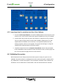
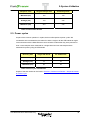
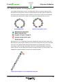
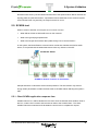
How can I … design a small reliable I/O system Tested Validated Documented Architecture Industrial Ethernet Networks Develop your project This document is for internal use only. Disclaimer This document is not comprehensive for any systems using the given architecture and does not absolve users of their duty to uphold the safety requirements for the equipment used in their systems or compliance with both national and international safety laws and regulations. Readers are considered to already know how to use the products described in this document. This document does not replace any specific product documentation. © 2010 Schneider Electric. All rights reserved. This document is for internal use only 3 The TVDA collection Tested Validated Documented Architectures (TVDAs) are designed to help project engineers and Alliance System Integrators during the development of a project. The TVDAs support users during the architecture selection and the project execution phases with an introduction to the system operating modes. Each TVDA is a starter kit that can provide users with: • Technical documentation • Application examples • Object libraries Each TVDA addresses one or several customer challenges within the proposed solution using the offer from Schneider Electric. All explanations and applications have been developed by both Schneider Electric experts and system integrators in our solution labs. The contributions from the system integrators help the kit’s content meet the expectations of our users. All TVDAs are illustrated with industry-specific applications to give more concrete examples of the methodology. TVDAs are not intended to be used as substitutes for the technical documentation related to the individual components, but rather to complement these materials and training. Development environment Each TVDA has been developed in one of our solution platform labs using a typical PlantStruxure architecture. PlantStruxure, the Process Automation System from Schneider Electric, is a collaborative system that allows industrial and infrastructure companies to meet their automation needs while also addressing growing energy management requirements. Within a single environment, measured energy and process data can be analyzed to yield a holistically optimized plant. This document is for internal use only 4 Table of Contents 1. Introduction...........................................................................8 1.1. Purpose ........................................................................................................................................................ 8 1.2. Customer challenges .................................................................................................................................... 8 1.3. Skill set prerequisites ................................................................................................................................... 8 1.4. Project methodology .................................................................................................................................... 9 2. Selection..............................................................................10 2.1. Network topology ....................................................................................................................................... 11 2.2. Selection criteria ........................................................................................................................................ 13 2.3. Device IP address assignment.................................................................................................................... 13 3. Design..................................................................................16 3.1. Products used............................................................................................................................................. 16 3.2. Suitable network topology for small standalone I/O system ...................................................................... 17 3.3. Installation guidelines................................................................................................................................ 18 3.4. Functional requirements ............................................................................................................................ 18 4. Configuration ......................................................................19 4.1. M340 Ethernet communication module ..................................................................................................... 19 4.2. STB dual port Ethernet module for Modbus TCP ...................................................................................... 29 4.3. Vijeo Citect................................................................................................................................................. 30 4.4. Validating the system ................................................................................................................................. 32 5. System validation ...............................................................33 5.1. Introduction................................................................................................................................................ 33 5.2 Application response time (ART) ................................................................................................................ 33 5.3. Power cycles .............................................................................................................................................. 35 5.4. Infrastructure redundancy ......................................................................................................................... 37 This document is for internal use only 5 5.5. SCADA test................................................................................................................................................. 38 6. Performance results...........................................................43 6.1 External application response time............................................................................................................. 43 6.2 Power cycle ................................................................................................................................................. 44 6.3. Citect SCADA screen update time.............................................................................................................. 46 List of Tables Table 1. Device Version Information ..................................................................................................... 11 Table 2. Network Topology Benefits Comparison ................................................................................. 13 Table 3 – Static IP Address Assignment via Software .......................................................................... 14 Table 4. Static IP Address Assignment via Web Page ......................................................................... 14 Table 5 – IP Address Assignment via BootP Server............................................................................. 15 Table 6. Served IP Address Assignment via DHCP.............................................................................. 15 Table 7. External ART Results .............................................................................................................. 34 Table 8. Internal ART Results ............................................................................................................... 35 Table 9. Power Cycle Test Results ....................................................................................................... 35 Table 10. External ART for a device failure recovery............................................................................ 37 Table 11. External ART for all islands after cable break ....................................................................... 37 Table 12. Citect SCADA ART................................................................................................................ 39 Table 13. SCADA Screen Update Time Tuned for Performance.......................................................... 40 Table 14. SCADA traffic effect on ART ................................................................................................. 40 Table 15. SCADA to COMM Module Cable Break................................................................................ 41 Table 16. Recovery Time after M340 COMM Module Replacement .................................................... 41 Table 17. Communication Recovery Time after M340 PLC Rack Power Cycle ................................... 42 Table 18. SCADA Recovery on Page Changes .................................................................................... 42 This document is for internal use only 6 List of Graphs Graph 1. External ART: Single STB Island ........................................................................................... 43 Graph 2. External ART: All STB Islands................................................................................................ 43 Graph 3. Power Cycle: Single STB Island............................................................................................. 44 Graph 4. Power Cycle: All STB Islands................................................................................................. 44 Graph 5. External ART for STB2 during Network Reconvergence ....................................................... 45 Graph 6. External ART for STB2 during Cable Break........................................................................... 45 Graph 7. Citect SCADA ART: Default Settings ..................................................................................... 46 Graph 8. Citect SCADA ART: Modified for Performance ...................................................................... 46 Graph 9. External ART with SCADA Traffic, NO Cache ....................................................................... 47 Graph 10. SCADA-to-BMX NOC 0401 Ethernet COMM Module.......................................................... 47 Graph 11. BMX NOC 0401 Replacement ............................................................................................. 48 Graph 12. M340 Rack Power Cycle ...................................................................................................... 48 This document is for internal use only 7 1-Introduction 1. Introduction 1.1. Purpose The purpose of this Tested Validated Documented Architecture (TVDA) is to present the design and performance of a standalone I/O system. The system incorporates an M340 PLC as the controlling device, using the Modbus TCP protocol and STB I/O as the remote devices. This TVDA will provide the following: • Network design that should be used for a small I/O system • Network architectures to prevent data interruption due to a cable break or an inoperable device • The overall performance of the specified system 1.2. Customer challenges When installing a new system, customers desire a cost-effective, simple system that provides network redundancy and reliable communication. They need more than a simple proof of concept. Customers must be confident that a system will work and perform within the expected operating range prior to purchasing and installing products. This TVDA addresses these challenges by recommending an appropriate network architecture and providing the performance results from the specified network. 1.3. Skill set prerequisites The reader will benefit from this document if they are already familiar with the following software applications and networking concepts. Software applications: • Unity Pro • Advantys Configuration Software • Vijeo Citect Ethernet knowledge: • Basic Ethernet networks • Basic understanding of network redundancy principles o Rapid Spanning Tree Protocol (RSTP) This document is for internal use only 8 1-Introduction 1.4. Project methodology This TVDA will guide the user through five phases: selection, design, configuration, implementation, and performance. During the selection phase, an effective architecture needs to be chosen for the specified devices. Various architectures and systems are presented here. The system that best satisfies the requirements will be the one that will be chosen for testing. The following chart illustrates our system design approach; each aspect will be addressed in the following sections: Project Specification Functional Constraints Operational Constraints Selection Configuration System Validation Performance Results S This document is for internal use only 9 2-Selection 2. Selection During the selection phase, an effective architecture needs to be chosen as well as the appropriate components for the project, according to your specific requirements. The requirements for this small stand alone I/O system are to provide a high availability system while being simple to maintain and cost effective. After examining various products within Schneider Electric’s solution offerings, the following two products are considered to be well suited for this system and its requirements. The BMX NOC 0401 module offers an embedded switch with four ports for Ethernet communications. Transparent to the user, the module can process both Modbus TCP and EtherNet/IP messages. (This TVDA concentrates on the Modbus TCP capabilities of the module). RSTP is a key feature supported by this module which becomes an integral part of a reliable I/O system. The STB NIP 2311 is a dual port Ethernet communication module with an embedded switch that supports RSTP, allowing a designer to establish a daisy chain loop or ring topology. This module supports Modbus TCP and can be configured via Advantys Configuration Software. In the following section, some network topology options are considered, and one is chosen as the focus of this TVDA. This document is for internal use only. 10 2-Selection Designation Reference Firmware versions Quantity 4 Port M340 Ethernet Communication module BMX NOC 0401 v1.0 1 Dual Port STB Ethernet module for Modbus TCP STB NIP 2311 V3.0 10 Table 1. Device Version Information 2.1. Network topology Many different topologies are available for the products specified above. In the following section we will examine each of the topologies and evaluate them against our required attributes: simplicity, redundancy, and cost 2.1.1. Star In a star topology all the devices are connected through a central device. This is an efficient use of network bandwidth because it spreads the traffic out through the star network. A broken cable or an inoperable device does not affect other devices on the network. However, a star topology does not provide redundancy, and a broken cable or inoperable device becomes a single point of failure for any devices that follow it on the network If the switch itself fails, all communication is lost. Additionally it is not very cost-effective since each device requires an individual cable connection back to the switch. Switch 2.1.2. Daisy chain The daisy chain topology has evolved from the bus architecture. Each device has an embedded switch, so an external switch is not needed. Although this saves money (by eliminating external switches and long cabling), it does not address redundancy. This document is for internal use only. 11 2-Selection Switch Embedded Switch Device Data Flow If a link between two devices is broken, then communication to all devices beyond the affected link is no longer possible. 2.1.3. Daisy chain loop using RSTP One way to solve communication interruption in a daisy chain network is to modify the network to create a daisy chain loop and implement a ring redundancy protocol such as RSTP. RSTP is an OSI layer 2 protocol defined by IEEE 802.1D 2004. As soon as it detects a redundant physical link in the network, it creates a logical loop-free tree structure topology. If RSTP is used in a ring topology with 10 to 20 devices, the network can recover from a broken wire or inoperable device in a matter of milliseconds. Switch This document is for internal use only. 12 2-Selection 2.2. Selection criteria The star network topology is well known, but it lacks redundancy and cost-effectiveness. The daisy chain network topology simplifies the network layout and reduces cost, but it does not provide redundancy. A daisy chain ring managed by a ring redundancy protocol is the one topology that addresses all three concerns for the required system. Simplicity Redundancy System Cost Star Daisy Chain RSTP Ring Table 2. Network Topology Benefits Comparison 2.3. Device IP address assignment When considering various methods of assigning IP addresses to I/O devices in the system, the method chosen must be reliable with as few steps as possible. The STB NIP 2311 supports: • Option 1: MAC-based default IP address 10.10.MAC.MAC • Option 2: Static IP address via the Advantys Configuration Software • Option 3: Static IP address via the STB NIP 2311 web pages • Option 4: Served IP address via BootP server • Option 5: Served IP address via DHCP server For more detailed information regarding steps for each procedure please refer to STB NIP2311 user guide, EIO0000000051. Option 1: MAC-based default IP address In general, plants do not use the default IP address of a device in the operating plant environment. The device must be given a new IP address. Once this new and unique IP address has been assigned, the module can be configured as required. The following will outline the general steps required to assign the IP address to the STB NIP 2311 using the options mentioned above. This document is for internal use only. 13 2-Selection Option 2: Static IP Address Assignment via Advantys Configuration Software 1 Adjust the rotary switches in front of the new module to Stored. 2 Connect to the module using a serial connection. If you are connecting through the Ethernet port, the IP address of the PC must be on the same subnet as the default IP address of the STB NIP 2311 module, 10.10.MAC.MAC. 3 Use the Module Editor to modify the IP address of the STB NIP 2311. 4 Save the configuration to the module by downloading its configuration. Table 3 – Static IP Address Assignment via Software Option 3: Static IP Address Assignment via STB NIP 2311 Web Pages 1 Adjust the rotary switches in front of the new module to Stored. 2 Change the IP address of your PC to 10.10.X.Y so that it is on the same network as the STB NIP 2311 default IP address. This will enable you to access the web pages of the new device 3 Access the embedded web pages of the device by entering the device’s default IP address in a web browser. Enter the new IP address and save the new IP parameters. 4 Change PC’s IP address back to its original IP address. This will enable it to communicate to all the devices on the network. 5 Place the module back on the network. When it powers up, the module will use the stored IP address configured via embedded web page. Table 4. Static IP Address Assignment via Web Page This document is for internal use only. 14 2-Selection Option 4: Served IP Address via BootP Server 1 Obtain the MAC address of the STB NIP 2311 island at boot-up. 2 Edit the BootP server, and remove the MAC address of the device to be replaced. Enter the MAC address of the new device that needs to obtain an IP address. 4 Adjust the rotary switches in front of the module to BootP. 3 Place the new device on the network Table 5 – IP Address Assignment via BootP Server Option 5: Assignment via DHCP server 1 Adjust the rotary switches of the new STB island to the same device name as the STB island that is being replaced. 2 Replace the previous device with the new device. Table 6. Served IP Address Assignment via DHCP The issue with assigning static IP addresses is that the IP address resides with the module’s configuration. If the module is replaced with a new module the entire process of assigning an IP address must be repeated each time. You can save a significant amount of time and resources by using either the FDR service or an address server to automate the task for you. The address server already has the device name as part of its configuration. By giving the replacement STB NIP 2311 the same device name, the module is able to obtain its IP address from the address server. During a plant startup, this becomes a key feature. Imagine the time and resources saved when more than 50 devices must obtain their IP addresses. Assigning IP addresses via DHCP (option 5) simplifies configuration and maintenance and saves project installation startup time. The system we recommend in this TVDA uses the BMX NOC 0401 as the DHCP server; it provides all the STB islands with their IP parameters. This document is for internal use only. 15 3-Design 3. Design 3.1. Products used The following is the list of products will be used to construct the small stand alone I/O system M340 PLC Platform: • BMXCPS2000 • BMXP342020 • BMXNOC0401 • BMXDDI1602 • BMXDDO1602 • BMXDRA1605 Modicon STB islands with dual port Modbus TCP: • STBNIP2311 • STBPDT3100 • STBDDI3610 • STBDDO3600 • STBDRC3210 • STBDDI3420 • STBDDO3410 • STBDDI3230 • STBDDO3200 • STBAVI1270 • STBAVO1250 • STBXBE2100 • TeSys U Cables: • M340 programming Cable • Ethernet CAT5e cables This document is for internal use only. 16 3-Design Software: • Unity Pro XL v5.0 • Unity Pro Ethernet Configuration Tool v1.0 • Advantys Configuration Software v4.7.0.4 • Vijeo Citect v7.1 3.2. Suitable network topology for small standalone I/O system To achieve reliability in the I/O network, the BMX NOC 0401 Ethernet communication module is used as the main switch. By enabling RSTP in the communication module, ports 3 and 4 can participate in the daisy chain ring. Architecture chosen for Small Stand Alone I/O System This document is for internal use only. 17 3-Design 3.3. Installation guidelines Below is an installation quick start sequence for assembling the system. Refer to the product user manual for detailed information on the products used. • Assemble all the I/O modules. • Wire all I/O modules to required motor starters. • Use the rotary switch on each of the Modicon STB modules to assign the device names. • Starting with the BMX NOC 0401 Ethernet module, connect port 3 to the bottom port of the first Modicon STB I/O module, then connect the top port of the first STB I/O module to bottom port of the second STB I/O module. Note: Do not connect the last STB to port 4 of the BMX NOC 0401 Ethernet module. The last link is connected after the Ethernet module has its configuration. 3.4. Functional requirements Certain parameters need to be considered before you set the values. Typically, CPU scan time is driven by the application; however, the frequency of requests sent to remote devices can be chosen. The repetitive rates that you configure should meet the application’s performance needs. As a rule of thumb, the data being requested should be updated twice during a CPU scan. This system requires a 50 ms CPU scan time. Therefore, the repetitive rate is configured for 20 ms. CPU scan 50 ms Repetitive rate 20 ms This document is for internal use only. 18 4-Configuration 4. Configuration Both Unity Pro v5.0 and the Unity Pro Ethernet Configuration Tool must be used to configure the (4-port) M340 Ethernet Communication module. The STB islands are configured via the Advantys Configuration Software. The overall system SCADA is created using Vijeo Citect software. This section provides the essential steps to configure the hardware. As mentioned in the prerequisites for the document, user should be sufficiently familiar with Unity Pro, Advantys Configuration, and Vijeo Citect software applications to create basic projects. Reference the pertinent user manuals if you need more information. 4.1. M340 Ethernet communication module In Unity Pro software, create a new project for the M340 platform, and populate the PLC bus with the appropriate CPU and the I/O modules. By default the CPU reserves 1024 words You will need to increase this amount for the BMX NOC 0401 and SCADA usage. To do this, double click on the CPU and increase the %MW size in the Configuration tab. Here is more detail about how to configure the BMX NOC 0401 Ethernet module: 1. After you have started a new project in Unity Pro software, open the Project browser, and double click on the PLC bus, 2. In the Hardware Catalog, open the communication folder, find the BMX NOC 0401 module in the list, and add it to the rack. 3. Once you place the module in the desired slot, a window will pop up requesting that an Alias name for the module. Use the default name or change it per the plant’s naming convention. 4. Click OK. This document is for internal use only. 19 4-Configuration BMXNOC0401 Module Properties Window The module is then placed in the rack and ready to be configured. 5. Double click on the module to configure the M340 Ethernet module memory location and size. Unity Pro – PLC bus 6. In the Configuration screen, assign the starting locations of the input and output registers and their respective sizes. Sixteen registers are reserved in the input and output memory locations for a connection health bit and a connection control bit, respectively. 7. The input and output starting indices and memory size for each of the parameters can be configured. For this application the following parameters were used: This document is for internal use only. 20 4-Configuration Unity Pro –BMX NOC 0401 Default Configuration 8. Once the modifications are done, click the Validate button. The Update application button will become highlighted and the project can be updated with the M340 Ethernet module’s memory allocation configuration. 9. Complete the configuration set up in the DTM Browser by choosing the Tools pull down menu and select DTM Browser. 10. Double click on the M_NOC0401 to launch the DTM. The remaining configuration can be completed. This document is for internal use only. 21 4-Configuration 4.1.1 Channel properties Some items in the Channel Properties menu need to be selected and modified. If the PC has more than one network card, use the Source IP Address pull down option to choose the IP address that is associated with the same network as the M340 Ethernet communication module. Ethernet Configuration Screen within Unity Pro In the sub-tree option TCP/IP, you can assign the IP address, sub-network mask and gateway for the BMX NOC 0401 Ethernet module. This document is for internal use only. 22 4-Configuration 4.1.2. Services Multiple parameters in the Services menu also need to be configured. The following topics step you through the RSTP, data exchange, and the address server setup. 4.1.2.1 RSTP RSTP functionality is enabled in the Services section of configuration screen. Once RSTP is enabled, a sub-tree option is displayed with additional parameter settings. One of these parameters, Bridge Priority; is used to identify which device in the network will act as the root of the RSTP tree. The root bridge in the RSTP network has the lowest bridge ID. To compare two bridge IDs, the priority is compared first. If two bridges have equal priority, then the MAC addresses are compared. In our network, the BMX NOC 0401 will be the root bridge. The STB NIP 2311 modules by default have a high number assigned for Bridge Priority. Accepting this default value identifies the BMX NOC 0401 as the root, and the branches of the tree will be distributed symmetrically. Note: Bridge ID is a combination of the Bridge Priority and the MAC address. Refer to RFC 802.1D 2004 for more information on Bridge role and its parameters. STB5 STB6 RSTP Service and Data Flow In a simple network where an even number of devices are being managed, it is likely that the link at the half-way point will be blocked. In the above system by looking at the web pages for STB5 and STB6 it was confirmed that the path between the two devices is blocked as indicated by the Discarding state on port 2 of STB6. This document is for internal use only. 23 4-Configuration 4.1.2.2 Add devices to be scanned Devices that you want to be part of the Ethernet module’s configuration must be added to the device list. From the DTM Browser, right click on the M_NOC0401 Ethernet module and select Add. From the listed devices select a Modbus Device. This document is for internal use only. 24 4-Configuration Provide an alias name to represent the device that is going to be controlled. In the Properties tab, change Items Management import mode to Manual. This enables you to create user-defined variables. The rotary switches on the STB islands have been set up to use DHCP via the device name. The BMX NOC 0401 is also to be used as the address server in this standalone system. In the Address Server section, modify the following parameters: IP address, DHCP Enabled, form of identification, and the device name for the Identifier. This document is for internal use only. 25 4-Configuration The Request Setting tab is used to configure read and write requests to the STB islands. Each STB island will have two requests: one for controlling and one to obtain STB island diagnostics at: a repetitive rate of 20 ms a health time out of 500 ms In the Device List, each request is itemized. Variables can be created for each request. This document is for internal use only. 26 4-Configuration Add the other 9 devices by following the instructions above. When all the devices have been added, select Device List from the configuration screen. A summary is displayed of all the devices that are being scanned and their connections. The BMX NOC 0401 configuration is now complete and ready to be built. From the Unity Pro Project Browser, double click the BMX NOC 0401 module in the rack, then click Update application. A set of derived variables is created; these variables can be used in the PLC logic. This document is for internal use only. 27 4-Configuration 4.1.2.3 Address server The Address Server selection from the Services menu displays the devices for which the M340 Ethernet module is the DHCP/FDR server. Devices that are part of the M340 Ethernet module’s configuration and have been configured for DHCP are listed in this screen. You can manually add other devices that are not being scanned separately. This document is for internal use only. 28 4-Configuration 4.2. STB dual port Ethernet module for Modbus TCP The Advantys Configuration Software is used to configure each island as follows: 1. Create a new workplace and add a new island. 2. From the Catalog Browser, expand STB Catalog, Networking and choose STB NIP 2311 v3.xx and drag it to the leftmost position on the island bus. This revision of the STB Ethernet network interface module supports RSTP. 3. Add the remaining power distribution and I/O modules. Place an island bus extension module as the last module on the island rack. 4. An island bus extension module must be the last module on the island rack. From the Catalog Browser, expand the Accessories folder and choose STB XBE 2100 v1.xx and drag it to the leftmost position in the next island rack. 5. From the Catalog Browser, expand the Enhanced CANopen folder and choose CANopen TeSys U Sc Ad- v1.xx. You can define some configuration parameters such as fallback strategy and the labels/variables by double clicking on the TeSys U module. Note: An STB island that includes a CANopen bus extension in its configuration cannot be uploaded from the device to the software. This document is for internal use only. 29 4-Configuration 6. The last parameter that must be set is the baud rate. In the Advantys Configuration Software, choose the Island pull-down menu from the tool bar, select Baud Rate Tuning , and set the baud rate to 500 kbps. 7. The configuration is now ready to build and download to the STB island. You can download either via Ethernet or through a Modbus serial cable. Note: Due to the CANopen bus extension, the RST button on front of the STB NIP 2311 module cannot be used to autoconfigure the island using default settings for all modules. 4.3. Vijeo Citect The Vijeo Citect software is Schneider Electric’s preferred SCADA system. Typically for a small system, SCADA redundancy is not required. In our implementation, therefore, all the servers will reside on one PC. Start a new project within Citect Explorer. The basic SCADA configuration comprises two procedures, as follows: 4.3.1. Configuring SCADA parameters 1. From the Citect Project Editor, choose the Servers pull-down menu, and create the system’s cluster, network addresses, alarm servers, report servers, trend servers, and I/O servers. This document is for internal use only. 30 4-Configuration 2. From the Communication pull-down menu, launch the Express Wizard the wizard will set up: the boards, ports, and I/O devices. Be sure to select TCP/IP as the board type and MODNET as the protocol so that all requests will use Modbus TCP as the protocol. 3. You may use the Citect Graphics Builder to create pages for this system. In order to have write access from the SCADA system to the PLC, a user with full privilege must be created prior to running the project. 4. Create several graphical pages to represent the I/O system, and use them to verify communications and see the status information of I/O devices in the architecture. These pages enable a user to observe and control the state of the STB I/O from the M340 Ethernet Communication module. This document is for internal use only. 31 4-Configuration 4.3.2. Importing Unity Pro variables into Vijeo Citect Software 1. From the Citect Project Explorer, choose the Tools pull-down menu and point to the location of the *.XSY file that contains the exported variables from Unity Pro software. 2. Pack the data that you want to pass to the SCADA in contiguous memory locations. This is a matter of good practice ,because when SCADA is polling the PLC for the register data over a Modbus TCP connection, it can optimize its performance by sending requests in blocks of 125 registers. This project has 625 tags in contiguous registers that are being polled by the SCADA system. 3. Compile the project and run the Computer Setup Wizard. Some of the parameters that are identified include the network model, the startup functions, and the page scan time. For this project the page scan time is set to 250 ms. 4.4. Validating the system Now that all devices are configured and the SCADA system is ready, the system can be validated. The tests are done in a building block manner, where the system is tested without any added traffic or network interruptions. Once a baseline is obtained, other conditions are introduced, such as cable break or SCADA traffic, and new measurements are collected. This document is for internal use only. 32 5-System Validation 5. System validation 5.1. Introduction One must know the feature set and performance requirements of a system in order to decide if it is a suitable system for the target application. It is just as important to know how the system behaves when exposed to stress. Particularly, does it recover from a fault and if so how fast? This section depicts various tests performed on the small I/O system followed by the results. 5.2 Application response time (ART) Two values are measured for ART to provide two different aspects of performance. The response times were measured two ways: • External ART: measured from the time a physical signal in the M340 PLC turns on and triggers a write command to an STB island until the island’s Vdc output relay turns on to signify that the data has been received. External Application Response Time This document is for internal use only. 33 5-System Validation • Internal ART: evaluates the time from when the request for write command is issued by the PLC to when the PLC receives status back from an STB island that data has been updated. Internal ART is meant to assist the user is gauging expected results for controlling devices in an RSTP network. Internal Application Response Time • In a system performance test, both external and internal ART are measured for an individual STB island and then repeated as a system for all 10 STB islands. Results can be used to establish the response time for the entire field of devices in the network. • As mentioned previously, there are two data paths in the RSTP network. Messages are sent from both port 3 and port 4 of the M340 Ethernet module, placing the blocked link between STB5 and STB6. The measurement of internal and external ART for all devices is done by evaluating data sent from the M034 Ethernet module and update confirmation response is received by STB5. 5.2.1. Application response time test results • ART measurements were taken from a representative system built according to the contents of this guide. The table below will summarize the findings for a quick overview. The results shown below are for more than 1000 samples. Response Time Single STB Island All STB Islands Minimum (ms) 119 122 Average (ms) 159 162 Maximum (ms) 196 198 Table 7. External ART Results Graphs of the test results can be found in Section 6, Performance Results - Graphical results of External ART. This document is for internal use only. 34 5-System Validation Response Time Single Advantys STB All Advantys STB Minimum (ms) 162 163 Average (ms) 178 222 Maximum (ms) 224 275 Table 8. Internal ART Results 5.3. Power cycles As part of the common operation in a plant, devices will experience power cycles. We conducted a test to evaluate the time taken for either a single or all the STB islands to regain communications with the M340 Ethernet communication module after they were powered on. Over a 1000 samples were measured for a single island and over 500 samples were measured for power cycling all STB islands. Recovery time Single STB Island All STB Islands Minimum (sec) 18 32 Average (sec) 19 43 Maximum (sec) 28 53 Table 9. Power Cycle Test Results Graphs of the test results can be found in Section 6, Performance Results - Graphical Results for Power Cycle This document is for internal use only. 35 5-System Validation 5.3.1. Effects of network reconvergence on ART As an additional performance check, we measured the ART for the device adjacent to the affected device during power cycling of a single STB island. For this small I/O network, the worst-case scenario would be to power cycle device 1(the device closest to the root bridge) and measure the effects of the network reconvergence by measuring device 2’s ART. Normal RSTP Path Device 1 being power cycled Because device 1 is no longer able to pass the messages to the devices down stream, the M340 Ethernet communication module must reroute the packets all the way around the daisy chain loop. In the graphic below the logical representation of the data path is shown. By comparing the ART of a single STB island to the ART of STB2 obtained during the above power cycle test, one can observe the network convergence effects on communication. This validates the network architecture chosen for the small I/O system. Logical representation of re-converged RSTP data path This document is for internal use only. 36 5-System Validation The table below shows that the network convergence on communication loss and recovery has no effect on the ART. Response time STB 2 Minimum (ms) 119 Average (ms) 158 Maximum (ms) 198 Table 10. External ART for a device failure recovery Graphs of the test results can be found in Section 6, Performance Results – Effects of Network Re-convergence on ART 5.4. Infrastructure redundancy The overall system integrity can be affected by many events such as; cable breaks between devices or an inoperable device. A cable break test was conducted to simulate an event that would result in a network reconvergence. Similar to the power cycle test, the worst-case scenario was chosen as the spot to break the cable link. Simulated Cable Break Test The External ART was measured during the test to validate the network’s integrity. The ART remained typical with no significant variance. Minimum ART Average ART Maximum ART 122 (ms) 159 (ms) 202 (ms) Table 11. External ART for all islands after cable break Graphs of the test results can be found in Section6, Performance Results – Effects of Network Re-convergence on ART This document is for internal use only. 37 5-System Validation No effects were seen by the simulation test because of the speed at which RSTP resolves the topology after the cable was broken. A specialized tool revealed that for the small I/O system under test the RSTP ring was fully converged in less than 10 ms. 5.5. SCADA test When it comes to SCADA, a few topics are of common concern: • What effects will the SCADA traffic have on the network? • What is the typical page update time? • What is the longest time without data update during loss of communication? In this system, the M340 Ethernet communication module also handles the SCADA traffic. Hence, it is important that the added task doesn’t have any effects on the ART. SCADA PC Station SCADA PC Station Location on the Network Sample tests were conducted to answer these questions. The final solution may result in tuning certain parameters to obtain the best result for SCADA without affecting the system’s ART. 5.5.1. Citect SCADA application response time SCADA Client to PLC ART evaluates the time from when the SCADA Client writes a value to the PLC, until the PLC receives and returns that value to the SCADA Client. The Citect SCADA Client then measures and calculates the time it took to complete the request. This document is for internal use only. 38 5-System Validation SCADA Client to PLC Application Response Time While running the SCADA with all the default settings, we took measurements to obtain screen update time. From the 1000 samples tested, the majority of SCADA screen update times varied from 200 ms to 360 ms with one measured as long as 520 ms. The data shows that at times more than 10 CPU scans are required to obtain all the data from PLC. Even though the update time is less than 1 second, the performance can be improved significantly by modifying a few parameters. Minimum (ms) Average (ms) Maximum (ms) 40 202 520 Table 12. Citect SCADA ART Graphs of the test results can be found in Section 6, Performance Results – SCADA ART To improve the performance of the SCADA, a few parameters were modified. In order to increase the number of requests sent to the I/O device, it is essential to know how many Modbus requests the communication module can handle simultaneously. The M340 Ethernet communication module can handle up to 8 Modbus requests prior to queuing them. This document is for internal use only. 39 5-System Validation The following parameters were added to the MODNET driver section using the Computer Setup Editor. • MaxOutstanding = 8 • MaxPending = 10 • AccumulateTime = 0 MaxOutstanding is the number of Modbus requests sent out simultaneously to the I/O device. MaxPending is the number of requests that can be pending a response from the I/O device. AccumulateTime is the waiting time before sending out a request once a response is received. For more information, refer to the Vijeo Citect help files. With the above parameters set, the SCADA update time now takes fraction of the time update all the values. All five requests were sent to the M340 Ethernet Communication module simultaneously. This adjustment improved the SCADA update time significantly. Minimum (ms) Average (ms) Maximum (ms) 40 59 80 Table 13. SCADA Screen Update Time Tuned for Performance Graphs of the test results can be found in Section 6, Performance Results – SCADA Screen Update Tuned for Performance Note: In systems that are not standalone, it is good practice not to use all server connections for SCADA usage. A few connections should be reserved for other explicit messages. 5.5.2. The effect of SCADA traffic on ART In this small standalone I/O system, the SCADA generates 5 requests to the PLC. The data is setup to be updated every second. The results shown are for over 500 samples. Minimum ART Average ART Maximum ART 128 (ms) 165 (ms) 201(ms) Table 14. SCADA traffic effect on ART Graphs of the test results can be found in Section 6, Performance Results - System ART with SCADA Traffic This document is for internal use only. 40 5-System Validation 5.5.3. SCADA-to-communication module cable break A simulated cable break in the plant was performed to measure the communication recovery time. The time is measured from when the cable is reinserted in the M340 Ethernet Communication module until data is updated on the SCADA page. The updating of data indicates that communications have been reestablished. Cable Removal at Communication Module Node Minimum (s) Average (s) Maximum (s) 8 22 31 Table 15. SCADA to COMM Module Cable Break Graphs of the test results can be found in Section 6, Performance Results - SCADA Cable Break 5.5.4. M340 Ethernet communication module replacement We also measured the SCADA update time when the BMX NOC 0401 was reseated in the PLC rack. The time was measured from when the module was reseated until communications were restored. Minimum (s) Average (s) Maximum (s) 33 53 96 Table 16. Recovery Time after M340 COMM Module Replacement This document is for internal use only. 41 5-System Validation Graphs of the test results can be found in Section 6, Performance Results - M340 Ethernet Communication Module Replacement 5.5.5. SCADA update time when the M340 PLC rack is power-cycled Another form of SCADA update time is to know the length of time it takes to reestablish communication after the rack has been powered on. The time is measured from the time the PLC rack’s power is restored until data is displayed on the SCADA page. Minimum (s) Average (s) Maximum (s) 34 49 60 Table 17. Communication Recovery Time after M340 PLC Rack Power Cycle Graphs of the test results can be found in Section 6, Performance Results - M340 PLC Rack Power Cycle 5.5.6. SCADA recovery on page changes/refresh time The validated results of refresh times when changing pages within the SCADA are recorded below. Screens were loaded with variable tags from all I/O devices so that an accurate generation of screen objects between pages could be observed. The following is the result of over 50 page changes to the SCADA client. During validation the SCADA client performed flawlessly and no interruptions to the communications were observed. Minimum (s) Average (s) Maximum (s) 0 0 0 Table 18. SCADA Recovery on Page Changes This document is for internal use only. 42 6-Performance Results 6. Performance results 6.1 External application response time Graph 1. External ART: Single STB Island Graph 2. External ART: All STB Islands This document is for internal use only. 43 6-Performance Results 6.2 Power cycle Graph 3. Power Cycle: Single STB Island Graph 4. Power Cycle: All STB Islands This document is for internal use only. 44 6-Performance Results 6.2.1. Effects of network reconvergence on ART Graph 5. External ART for STB2 during Network Reconvergence Graph 6. External ART for STB2 during Cable Break This document is for internal use only. 45 6-Performance Results 6.3. Citect SCADA screen update time 6.3.1. Citect SCADA ART – default settings Graph 7. Citect SCADA ART: Default Settings 6.3.2. Citect SCADA ART – tuned for performance Graph 8. Citect SCADA ART: Modified for Performance This document is for internal use only. 46 6-Performance Results 6.3.3. Effect of SCADA traffic on ART Graph 9. External ART with SCADA Traffic, NO Cache 6.3.4. SCADA Cable break SCADA Cable Break n = 25 14 Frequency 12 10 8 6 4 2 0 5 10 15 20 25 30 35 More Time (seconds) Graph 10. SCADA-to-BMX NOC 0401 Ethernet COMM Module This document is for internal use only. 47 6-Performance Results 6.3.5. SCADA – M340 Ethernet communication module replacement M340 Ethernet Module Replacement Frequency n = 25 8 7 6 5 4 3 2 1 0 20 30 40 50 60 70 80 90 Time (seconds) Graph 11. BMX NOC 0401 Replacement 6.3.6. SCADA: M340 rack power cycle Graph 12. M340 Rack Power Cycle This document is for internal use only. 48 Schneider Electric Industries SAS Head Office 35, rue Joseph Monier 92506 Rueil-Malmaison Cedex FRANCE www.schneider-electric.com Due to evolution of standards and equipment, characteristics indicated in texts and images in this document are binding only after confirmation by our departments Print: Version 2.0 – 01 2011