1
Service Handbook
HP Apollo 9000 Series 700
Model 735 Workstations
This is an unreleased, corrected version of
Order No. A2095 –90602,
produced for online access.
00893
Click to go to the Table of Contents
P!l HEWLETT
PACKARD
300 Apollo Dr., Chelmsford. MA 01824
NOTICE
The information contained
in this document is subject to change without notice
HEWLETT-PACKARD
MAKES NO WARRANTY OF ANY KIND WITH REGARD TO THIS MANUAL, lNCLUDING, BUT NOT LIMITED TO, THE IMPLIED WARRANTIES OF MERCHANTABILITY AND FITNESS FOR A
PARTICULAR PURPOSE,
Hewlett-Packard
shall not be liable for errors contained herein or direct, indirect, special, incidental or consequential damages in connection with the furnishing performance or use of
this material,
WARRANTY
A copy of the specific warranty terms applicable to your Hewlett –Packard
can be obtained from vour local Sales and Service Office.
product and replacement parts
Copyright @ Hewlett –Packard Company 1992
This document contains information which is protected by copyright.
All ri:g,ts are reserved. Reproduction,
adaptation,
or translation without prior written permission is prohibited, except as allowed under the copyright laws.
Restricted RiL@t Legend
Use, duplication or disclosure by the U.S. Government Department of Defense is subject to restrictions as set forth in
paragraph (b)~3 j(ii) of the Ri@ts
in Technical Data and Software clause in FM
52.227–7013.
Copyright @AT & ~ Inc. 1980,1984
Copyright @ The Regents of the University of California 1979,1980,1983
This software and documentation
is based in part on the Fourth Berkeley Software Distribution under licence from the
Regents of the University of California.
ii
Printing History
New Editions of this manual incorporate all material updated since the previous
edition. Update packages may be issued between editions and contain replacement and additional pages to be merged into the manual by the user.
The manual printing date and part number indicate its current edition. The printing date changes when a new edition is printed. (Minor corrections and updates
which are incorporated at reprint do not cause the date to change.) The manual
part number changes when extensive technical changes are incorporated.
Edition 1
Original service handbook for Model 735
●
mm
111
Emissions Regulations
Federal Communications
Commission
(FCC)
The Federal Communications Commission of the U.S. government regulates the
radio frequency energy emanated by computing devices through pubhshed regulations. These regulations specify the limits of radio frequency emission to protect
radio and television reception. All HP Apollo nodes and peripherals have been
tested and comply with these limits. The FCC regulations also require that computin~ devices used in the U.S. display the agency’s label and that the related document~tion include the following statement:
WARNING:
This equipment has been tested and found to comply with the
limits for a Class A digital device, pursuant to part 15 of the
FCC rules. These limits are designed to provide reasonable
protection against harmful interference when the equipment is
operated in a commercial environment. This equipment
generates, uses, and can radiate radio frequency enerb~ and, if
not installed and used in accordance with the instruction
manual, may cause harmful interference to radio
communications. Operation of this equipment in a residential
area is likely to cause harmful interference in which case the
user will be required to correct the interference at his own
expense.
Compliance to these regulations requires the use of shielded cables.
Canadian Department
of Communications
(DOC)
This digital apparatus does not exceed the Class A limits for radio noise emissions
from d;gital apparatus as set out in the Radio Interference Requirements of the
Canadian Department of Communications.
Compliance to these regulations requires the use of shielded cables.
Emissions
Regulations
Compliance
Any third–party 1/0 device installed in HP Apollo system(s) must be in accordance with the requirements set forth in the preceding Emissions Regulations
statements. In the event that a third –party noncompliant 1/0 device is installed,
the customer assumes all responsibility and liability arising therefrom.
Compliance to these regulations requires the use of shielded cables.
iv
DECURATION OF CONFORMITY
according to EWIEC Guide22and EN 45014
Manufacturer’s
Name:
Hewlett-Packard
100 DomainDrive
IMe@r,NW U.S.A.
declares, that the product
Product: Computer Workstation
Model Numbe~
735
Product Number:
A1946A
conforms to the folluwing Product Specifications:
Safety
IEC 9S&1986/ EN60950 (1988)
EMC:
CISPR 221985/EN 55022 (1988) Chss A
lEC 801-2:1991 / pr EN55101-2 (1990): 3 kV CD, 8
IEC 801-31984/
pr EN554)24-3(1991~ 3 V/m
Supplementary Information:
kV AD
The prodwt was tested in a typical Hewlett-Packard
Workstation mnfiguration.
Zxeter, Date
Nov. 12,1992
James H. Kelly
Division Quality Manager
European Comtac& lbur heal Hewlet-Packard Saks and Service OffIce or HewlettPackard GmbH, Department ZQKMm@wds EUIWW Hernmberger X)0, D-7030 Boeblingen
(FAX+ 49-7031-141623)
This is a Class A product. In a domestic environment this product may cause radio
interference in which case the user may be required to take adequate measures.
v
I
Electrostatic
Discharge
(ESD) Precautions
Electrostatic charges can damage the integrated circuits on printed circuit boards.
TO prevent
such damage
from
ckxming,
&bserve the following precautions when
unpacking and installing the board.
●
Stand on a static–free mat.
●
Wear a static strap to ensure that any accumulated electrostatic charge discharges from your body to ground.
●
Connect all equipment together, including the static–free mat, static straps,
routing nodes, and peripheral units.
.
Keep uninstalled printed circuit boards in their protective antistatic bags.
●
Once you have removed the printed circuit boards from their protective antistatic bags, handle them by their edges.
Table of Contents
Product Information
1
Product Description . . . . . . . . . . . . . . . . . . . . . . . . . . . . . . . . 1–2
System Unit Controls . . . . . . . . . . . . . . . . . . . . . . . . . . ..OO. 1–3
Power Switch . . . . . . . . . . . . . . . . . . . . . . . . . . . . . . . . . . . . . 1–4
Power LED . . . . . . . . . . . . . . . . . . . . . . . . . . . . . . . . . . . . . . 1–4
TOCSwitch . . . . . . . . . . . . . . . . . . . . . . . . . . . . . . . . . . . . . . 1–4
Service/NormalModeSwitch...
. . . . . . . . . . . . . . . . . . . . 1–4
UnderstandingtheL Ems......
. . . . . . . . . . . . . . . . . . . . . . 1–5
System Unit Rear Panel Connectors
. . . . . . . . . . . . . . . . . . . 1–7
SystemI/OConnectors
. . . . . . . . . . . . . . . . . . . . . . . . . . . . 1–8
HP–HIL connector . . . . . . . . . . . . . . . . . . . . . . . . . . . . . . . 1–8
HPParallelI/Oconnector
. . . . . . . . . . . . . . . . . . . . . . . . . . 1–8
Network connectors . . . . . . . . . . . . . . . . . . . . . . . . . . . . . . . 1–8
RS–232SerialInput/Outputconnectors
. . . . . . . . . . . . . . 1–9
Audio connectors . . . . . . . . . . . . . . . . . . . . . . . . . . . . . . . . 1–10
SCSII/OConnectors
. . . . . . . . . . . . . . . . . . . . . . . . . . . . . 1–11
GraphicI/OConnector
. . . . . . . . . . . . . . . . . . . . . . . . . . . 1–12
EISAI/OConnector
. . . . . . . . . . . . . . . . . . . . . . . . . . . . . 1–12
Monitor Controls, Connectors, and Indicators . . . . . . . . . 1–13
Environmental/Installation/PM
Environmental Specifications
Regulatory Requirements . . .
Installation . . . . . . . . . . . . . . .
Preventive Maintenance . . . .
2
...
....
....
....
.
.
.
.
.
.
.
.
.
.
.
.
.
.
.
.
.
.
.
.
...
...
...
...
..
..
..
..
Configuration
.
.
.
.
.
.
.
.
.
.
.
.
.
.
.
.
.
.
.
.
.
.
.
.
.
.
.
.
.
.
.
.
.
.
.
.
2–1
2–2
2–2
2–2
. . . . . . . . . . . 3–1
. . . . . . . . . . . . . . . . . . . . . . . . . . . . . . . . 3–1
Mass Storage Configurations..
InstallingAdditonal
.
.
.
.
3
Workstation and System Unit Configurations
FRU Configurations
.
.
.
.
Memory...
. . . . . . . . . . . . . . . . . . . . . . . 3–1
. . . . . . . . . . . . . . . . . . . . . 3–12
vii
.’
‘lloubleshooting
LED Error Codes
4
. . . . . . . . . . . . . . . . . . . . . . . . . . . . . . . . . 4–2
Dealingwith a Boot Failure . . . . . . . . . . . . . . . . . . . . . . . . . 4–12
Boot Administration Environment . . . . . . . . . . . . . . . . . . 4–13
Stable Storage . . . . . . . . . . . . . . . . . . . . . . . . . . . . . . . . . . . 4–14
Boot Command Notations . . . . . . . . . . . . . . . . . . . . . . . . 4–15
Supported Foot paths . . . . . . . . . . . . . . . . . . . . . . . . . . ..4–15
Invoking the ISLEnvironment froma SCSI Device . . . 4–15
ISLEnvironment
. . . . . . . . . . . . . . . . . . . . . . . . . . . . . . . . 4–17
ISLUser Commands . . . . . . . . . . . . . . . . . . . . . . . . . . . . . 4–17
Running the Disk–BasedISL
Diagnostics . . . . . . . . . . . 4–18
Verifying the System Operation with SupportWave
Field Replaceable
Units
. . . . . 4–19
5
Pedestal Feet . . . . . . . . . . . . . . . . . . . . . . . . . . . . . . . . . . . . . . 5–4
Top Cover . . . . . . . . . . . . . . . . . . . . . . . . . . . . . . . . . . . . . . . . . 5–5
Power Supply . . . . . . .. o......
. . . . . . . . . . . . . . . . . . . . . . . 5–7
Backplane/FanAssembly
. . . . . . . . . . . . . . . . . . . . . . . . . . . . 5–8
Disk Drives . . . . . . . . . . . . . . . . . . . . . . . . . . . . . . . . . . . . . . 5–10
CoreI/OandProcessorBoard..
. . . . . . . . . . . . . . . . . . . . . 5–12
System EEPROM . . . . . . . . . . . . . . . . . . . . . . . . . . . . . . . . 5–13
Memory . . . . . . . . . . . . . . . . . . . . . . . . . . . . . . . . . . . . . . . . 5–14
Calendar Battery . . . . . . . . . . . . . . . . . . . . . . . . . . . . . . . . . . 5–16
LANSliderModule
. . . . . . . . . . . . . . . . . . . . . . . . . . . . . . . 5–17
Graphics Board . . . . . . . . . . . . . . . . . . . . . . . . . . . . . . . . . . . 5–18
FrontControlPanel
. . . . . . . . . . . . . . . . . . . . . . . . . . . . . . . 5–19
Diagrams
6
Reference
7
Installation Manual . . . . . . . . . . . . . . . . . . . . . . . . . . . . . . . . . 7–1
Service Manuals . . . . . . . . . . . . . . . . . . . . . . . . . . . . . . . . . . . 7–1
Reference Manuals . . . . . . . . . . . . . . . . . . . . . . . . . . . . . . . . . 7–1
Service Notes
Vm
● 00
8
. .
Figures
1–1
1–2
Power Switch Location . . . . . . . . . . . . . . . . . . . . . . . . . 1–3
TOC and Service/Normal Mode Switch Locations . . 1–4
1–3
1–4
1–5
1–6
1–7
1–8
System LEDs . . . . . . . . . . . . . . . . . . . . . . . . . . . . . . . . . 1–5
Troubleshooting System LEDs . . . . . . . . . . . . . . . . . . 1–6
Mode1735Rear Panel Connectors . . . . . . . . . . . . . . . 1–7
Audio Connectors . . . . . . . . . . . . . . . . . . . . . . . . . . . . 1–10
19–Inch, Color Monitor (ModelA2094)
. . . . . . . . . 1–14
19–Inch, Grayscale Monitor (ModelA2088A)
. . . 1–15
3–1
DefaultSCSIIDs
3–2
3–3
Quantum 210–MB Winchester Drive Jumpers . . . . . 3–3
Hewlett–Packard 420–MBWinchester
Drive Jumpers
(Early Model) . . . . . . . . . . . . . . . . . . . . . . . . . . . . . . . . 3-4
Hewlett –Packard 420–MB Winchester Drive Jumpers
(Late Model) . . . . . . . . . . . . . . . . . . . . . . . . . . . . . . . . . 3–5
Quantum 525 –MB Winchester Drive Jumpers . . . . . 3 –6
Seagate 525 –MB Winchester Drive Jumpers . . . . . . 3 –7
Hewlett –Packard 1– GB Winchester Drive Jumpers
(Single–Ended)
. . . . . . . . . . . . . . . . . . . . . . . . . . . . . . 3-8
Micropolis 1– GB Winchester Drive Jumpers
(Single–Ended)
. . . . . . . . . . . . . . . . . . . . . . . . . . . . . . 3–9
3–4
3–5
3–6
3–7
3–8
3–9
. . . . . . . . . . . . . . . . . . . . . . . . . . . . . 3–2
3–lo
3–11
Hewlett –Packard 1– GB Winchester Drive Jumpers
(Fast/Wide) . . . . . . . . . . . . . . . . . . . . . . . . . . . . . . . . . s–10
Floppy Address Jumper Settings . . . . . . . . . . . . . . . . 3–11
Installing Memory Cards . . . . . . . . . . . . . . . . . . . . . . 3–13
4–1
Front Panel LEDs . . . . . . . . . . . . . . . . . . . . . . . . . . . . . 4–2
5–1
5–2
Removing Pedestal Feet . . . . . . . . . . . . . . . . . . . . . . . . 5–4
Removing Top Cover Screws . . . . . . . . . . . . . . . . . . . . 5–5
Lifting Top Cover . . . . . . . . . . . . . . . . . . . . . . . . . . . ..5–6
Removing the Power Supply . . . . . . . . . . . . . . . . . . . . 5–7
Backplane/Fan Removal . . . . . . . . . . . . . . . . . . . . . . . . 5–8
Removing the Fans and Backplane Assemby . . . . . . . 5–9
Removing the First Disk Drive . . . . . . . . . . . . . . . . . 5–10
Mounting the Disk Drive Assembly on the Disk Tray 5 – 11
Connecting Cables tothe Disk . . . . . . . . . . . . . . . . . 5–11
Removing the Core I/Oand Processor Boards . . . . 5–12
Component Locations . . . . . . . . . . . . . . . . . . . . . . . . 5–13
Removing Memory Boards . . . . . . . . . . . . . . . . . . . . 5–14
5–3
5–4
5–5
5–6
5–7
5–8
5–9
5–lo
5–11
5–12
ix
5–13
Removing the Calendar Battery . . . . . . . . . . . . . . . . 5–16
5–14
LAN Slider Module Removal
5–15
Removing the Front Control Panel . . . . . . . . . . . . . . 5 –19
6– 1
System Unit Functional Block Diagram . . . . . . . . . . . 6–2
. . . . . . . . . . . . . . . . . . 5–17
Tables
1– 1
l–~
LED Display During Normal System Activity . . . . . . 1–6
Serial I/O Pins eeo. oo. eo. oo. oeoao . .. O.O. OOO...O 1–9
2– 1
Environmental Specifications for Model 735 SPU . . 2– 1
4–1
4–2
Selftest LED Codes . . . . . . . . . . . . . . . . . . . . . . . . . . . 4–3
PDCLEDCodes
coooe. oo. ..e. ..e . . .. O. . . . .. O.. 4–7
4–3
4–4
ISLLED Codes . . . . . . . . . . . . . . . . . . . . . . . . . . . . . . . 4–9
HP–UXKernel
LED Codes . . . . . . . . . . . . . . . . . . . 4–11
5–1
FRUList
. . . . . . . . . . . . . . . . . . . . . . . . . . . . . . . . . . . . 5–2
❑
❑
x
n
o
1
Product Information
This chapter introduces the HP Apollo 9000 Series 700 Model 735 workstation.
Its purpose is to familiarize you with the workstation and its controls and indicators. Included in this chapter are the following topics:
o
Product description
0
System unit controls
●
Understanding the LEDs
●
System unit rear panel connectors
●
Monitor controls, connectors, and indicators
Product Information
1-1
Product Description
The Model 735 is a high–performance, PA–RISC–based
si~g+edto run the HP– UX operating system.
workstation that is de-
The Model 735 workstation houses up to two internal mass storage devices connected to one of two internal SCSI interfaces: single-ended or fasthvide. With the
single– ended interface, the workstations have their first hard disk drive bay fitted
with either a 525 –MB or 1– GB hard disk drive. The second disk bay maybe
fitted with either a 3.5 –inch floppy drive or a 525 –MB or 1–GB hard disk drive.
With the fast/wide interface, the workstations have their hard disk drive bays fitted
with either one or two 1– GB hard disk drives. Hard disk drives are pre – formatted. (The 1– GB drives are not interchangeable between single– ended and
fast/wide interfaces.)
The Model 735 workstation contain the following key features:
●
Operating Systems
. Compatibility
●
Graphics Options
@ Main Memory
Source and binary code compatible with
Series 700 product family
19–inch 1280 x 1024 8–plane color
19–inch 1280 x 1024 24–plane color
Dual 19–inch 1280 x 1024 24–plane color
19–inch 1280 x 1024 24–plane Z-buffered
19–inch 1280 x 1024 48–plane Z–buffered
19–inch 1280 x 1024 8–bit grayscale
color
color
32 MB (16 MB on–board CPU; non–removable)
Up to 400 MB: removable memory cards
Mass Storage,
single ended SCSI
3.5 —inch SCSI hard disk drive
Optional second hard disk drive or
Optional 3.5 – inch flexible disk drive
G;ss Storage,
fast/wide SCSI
3.5 —inch SCSI hard disk drive
Optional second hard disk drive
●
Network
Thin LAN. or
LAN AUI, or
FDDI
●
1/0
Two 9 –pin RS – 232 ports
One 25 –pin HP parallel port
8–bit. single–ended SCSI–2 interface
16–bit. fast, wide. SCSI–2 interface
HP–HIL port for HP–UX keyboards and other
HP-HIL devices
CD – quality audio and speaker output
CD–quality microphone and audio input
●
l-~
Native HP–UX
Product Information
System Unit Controls
Before powering on the system, you should become familiar with the system unit
controls.
This chapter introduces the HP Apollo 9000 Series 700 Model 735 workstations.
Its purpose is to familiarize you with the workstation and its controls and indicators. Included in this chapter are the following topics:
●
Product description
●
System unit controls
●
Understanding the LEDs
●
System unit rear panel connectors
c Monitor controls, connectors, and indicators
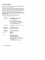
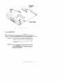
Figure 1– 1 shows the power switch and the Power LED.
I
Front
\
Power
LED
\
~ower.vvitch
Figure 1 – 1. Power SwitchLocation
Figure 1– 2 shows the location of the TOC (Transfer Of Control) and Service/Normal Mode switches. These switches are located behind a hinged cover on the front
of the system unit.
Product Information
1–3
\
Power
LED
Hinged
Front
Cover
TO
)
Front (Hinged Cover Opened)
Figure1 –2. TOC and Service/Nomal Mode SwitchLocations
Power Switch
Use the power switch to power the system unit on and off.
Power LED
The power LED lights green when the system unit it powered on.
TOC Switch
Use the TOC switch to reset the operating system. Do not push the TOC switch
unless you have first shutdown the system.
Service/Normal
Mode Switch
The Service/Normal mode switch is by default in the Normal position. Service
mode is used only during manufacturing.
1-4
Product Information
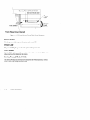
Understanding
the LEDs
There are 9 light –Emittinq Diodes (LEDs) on the system. Five are visible from
the front of the system uni~when the hinged door is closed, as shown in Figure
Figure 1– 3. The green LED on the far right is the Power LED. It lights when the
system unit power is on. The remaining four amber LEDs show that the system is
running the operating system and communicating over the network.
\
V4
System
Status LEDs
J!!l
-
\
43*3.$.==
mull
k
Power
LED
(Hinged Door Closed)
Figure 1 –3. SystemLEDs
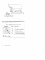
If you open the hin~ed door, there are four additional amber LEDs as shown in
Fi~ure 1– 4). Thes~LEDs help you to troubleshoot the workstation b y coming on
in~ertain patterns during system failures (see Chapter 6).
Product Information
1-5
System
Status LED
(8 through 1) -
)
Power
LED
Front (Hinged Door Opened)
Figure 1–4. TroubleshootingSystem LEDs
Table 1– 1 lists how the four system LEDs report during normal HP–UX system
activity. The green Power LED remains lit while the system is powered on.
Table 1 – 1. LED Displa}’ Duting Normal System Activitv
d
LED Display
Symbol
Meaning
S7654321
IHHIUHNHI
QQ
Operating System Running
UHHH191HI
w
>
Disk Access In Progress
UHHHHllo
o@’E
n
Network Receive In Progress
UHHHHHll
0+:
Network Transmit In Progress
l-!
= LED On or Flashing
/
1-6
Product Information
❑
.!
System Unit Rear Panel Connectors
This section describes the four main 1/0 subsystems on the system unit’s rear
panel:
●
System 1/0 Connectors
●
Graphic 1/0 Connectors
●
Disk 1/0 Connectors
●
EISA 1/0 Connectors
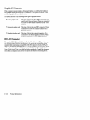
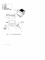
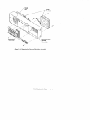
Figure 1– 5 shows the location of the connectors as well as the ac power connector
on”the system’s rear panel.
NOTICE:
To maintain FCC/EMI compliance, verify
that all cables are fully seated and properly
fastened.
Figure 1 –5. Model 735 Rear Panel Connectors
Product Information
1-7
System 1/0 Connectors
●
HP —HIL connector
●
HP parallel 1/0 connector
●
802.3 network connectors
.
RS —232 serial input/output connectors
HP-HIL
connector
The onboard Hewlett –Packard Human Interface Link (HP–Hil) port provides
support for 2 standard and 5 optional HP-Hil devices. The (two– dot) HP–HIL
connector on the bulkhead supports the standard HP– HIL keyboard. The keyboard provides an HP–HIL connector for the standard HP–HIL 3 –button
mouse. Consult the documentation that accompanies each input device for specific
information concerning its use.
HP Parallel
1/0 connector
The 25 –pin HP Parallel 1/0 interface port is provided for use with peripheral devices using the Centronics interface protocols such as printers and plotters. Consult the documentation that accompanies each peripheral device for specific information concerning its use.
Network
connectors
The system provides a connector for LAN through a removable daughter card of
the system 1/0 board. Three LAN options are available: a BNC connector for a
ThinLAN IEEE 802.5 network. an AUI external connector for a MAU to an IEEE
802.3 network. or a connector for an FDDI network.
1-8
Product Information
RS-232
Serial Input/Output
connectors
You can attach a variety of peripheral devices to the two RS–232 Serial Input/
Output (S10) ports on the workstation. These peripheral devices include printers,
plotters, modems. and scanners. Consult the documentation that accompanies
each peripheral device for specific information concerning its use.
Both S10 ports are programmable. You can set functions such as bit rate, character
length, parity, and stop bits. S10 Ports 1 and 2 are used as interfaces for serial
asynchronous devices to the CPU. Both ports operate at up to a 19.2K baud rate.
The interface to S101 and 2 is by way of RS – 232 drivers and receivers.
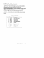
Table Table 1– 2 shows the S10 connector pin listings. The serial connectors are
9–pin D–sub connectors. Signal names are those specified in the EIA RS–252
standard;
Table 1 –2. Serial 1/0 Pins
Pin No.
Signal
Description
1
~
5
DCD
RXD
TXD
DTR
GND
Data Carrier Detect
Receive Data
Transmit Data
Data Terminal Ready
Ground
6
DSR
Data Set Ready
7
RTS
CTS
RI
Request To Send
Clear To Send
Ring Indicator
3
4
8
9
Product Information
1– 9
Audio
connectors
The workstation has audio input and output capability through external input and
output connectors and an internal speaker. A microphone for audio input is not
supplied with the workstation. The audio connectors are standard audio mini —
jacks. Hewlett –Packard recommends that for best quality recording and playback
of audio through the external connectors, that you use gold–plated plugs available
through audio retailers. For more information on the audio capability of the workstation see the Audio Users Guide manual. Figure 1– 6 shows the audio connectrs
on the rear of the workstation.
Mono Speaker
r Earphones
Figure 1 – 6. Audio Connectors
1-1o
Product Information
SCSI 1/0 Connectors
The system contains four (4) SCSI connectors:
●
External SCSI OUT Connector
Q Internal SCSI IN Connector
●
System Single—Ended SCSI Connector
●
System Fast/Wide SCSI Connector
NOTICES:
When attaching external SCSI devices, be
sure to terminate the last device on the external SCSI bus. If no external SCSI devices are
attached. the SCSI terminator that was
shipped with the workstation should be connected to the external SCSI connector.
HP does not provide maintenance for SCSI
devices not sold by HP For a list of SCSI devices that are sold by HP, contact the sales
representative.
Product Information
1–11
Graphic 1/0 Connector
1
If the computer system includes a bitmapped display, you will find the bulkhead
for a graphic device just below the 1/0 bulkhead. If the system is a server, it will
not have a graphic d“eviceat this location.
The system has one of the following three types of G
graphic devices:
@ Color graphic card
.
This type of device has three BNC connectors (one
each for red. blue, and green). These are connected
by a cable to three similar connectors on the color
monitor.
●
Grayscale graphic card
This type of device has one BNC connector. This is
connected by a cable to a similar connector on a
Orayscalemonitor.
a
●
Graphic interface card
This type of device has a special connector. It is
connected to an external graphic processor, which
in turn is connected to a video display monitor.
EISA 1/0 Connector
The one slot EISA (Extended Industry Standard Architecture) 1/0 port is a superset of ISA Industry Standard Architecture). It extends the capabilities of that
standard wL ile maintaining compatibility with ISA expansion boards. EISA provides 32 – bit memory addressing and 52–bit data transfers. The EISA slot allows
quick and easy integration in heterogeneous networks as well as simple connections of high – speed. low– cost disks and other peripherals. Consult the documentation that accompanies each device for specific information concerning its use.
1-12
Product Information
Monitor Controls, Connectors, and Indicators
Before using the monitor. you should become familiar with its controls, connectors, and indicators.
‘
The Power– On LED, when lit. indicates that the monitor has ac power applied.
Use the following controls to adjust the monitor:
●
The Power – on button turns the monitor’s power on and off,
●
The Brightness control adjusts the brightness of the display.
Q The Contrast control adjusts the light —to —dark and dark—to —light contrast
of the display.
●
The Degauss control demagnetizes the monitor. Degaussing disperses any
accumulated magnetic change from the face of the monitor. Magnetic disturbances such as picture distortion or color impurity can be caused by either
moving the monitor from one place to another or swiveling the monitor on
its base.
The following figures
illustrate the monitors for the workstation.
b
Figure 1–6 shows the 19–inch, color monitor.
Figure
1-7 shows the 19- inch, grayscale monitor.
b
Product Information
1–13
i
1
2
3
4
5
6
7
V-STAT
H-STAT
V-CENT
Brightness
Contrast
Power-On LED
Power ON/OFF Button
Front
Ie
rs
c
Figure 1 – 7. 19–Inch, ColorMonitor (ModelA2094)
1-14
Product Information
,,>
1
2
3
4
Brightness
Contrast
Power-On LED
Power ON/OFF Button
3
/
4
ml
Rear
Power
Connector
II
Ea
1
[
Connector
Figure 1–8. 19–Irzch, Grayscale Monitor (ModelA2088)
❑ ID
❑ o
Product Information
1–15
Environmental/
Installation/PM
2
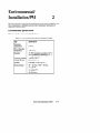
This chapter lists the environmental specifications for the system and lists the regulator requirements. Installation and Preventive maintenance information, if
appl[cabl~, is also provided.
A
Environmental
Specifications
Table 2– 1 lists the environmental specifications.
Table 2–1. Environmental Specificationsfor Model 735 SPU
Type
Specification
Operating
Temperature
5–40° c
Non– Operating
Temperature
–30–70° c
Humidity
15- 80$%maximum operating @ 40° C
90% maximum nonoperatin~@ 650 C
(for 12 hours)
Operating Altitude
Storage Altitude
3100 m @ 40” C
4600m @ 70° C
Acoustic
Less than 5.0 BELS @ 40° C
Electrical Input
90 – 132 Vac or 180 – 264 Vat,
47 – 66 Hz
540 Watts max.
1843 BTU/hour
465 Kcal/hour
Environmentalflnstallation/PM
2–1
Regulatory Requirements
The following regulatory requirements are met:
●
FCC Class A
●
CSA C22.2 No. 950M
o VCCI Class 1
●
EN 55022 Class A / CISPR 22 Class A
●
UL1950
.
TUV/GS Mark
– IEC 950/EN60950
– zH1/618
Installation
Refer to the installation and users manuals:
Preventive Maintenance
There is no preventive maintenance for the system unit. Removable media storage
devices may require operator preventive maintenance. Refer to the respective
manual.
❑ n
❑ o
2-2
Environlmental/Installation/PM
3
Configuration
This chapter provides details on setting up and changing the system
configuration.
Workstation and System Unit Configurations
Refer to the HP Apollo 9000 Series 700 Configuration Guide for a complete list of
supported accessories, peripherals, and operating systems.
FRU Configurations
This section provides information for setting up or changing the configuration of
the system Field Replaceable Units (FRUS).
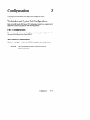
Mass Storage Configurations
Figures 5 – 1 throu~h
a 3 – 10 show the SCSI ID settings for mass storage devices.
NOTICE:
The SCSI terminators must be removed from all internal SCSI devices.
Configuration
3– 1
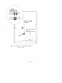
Internal System Drives:
System SCSI Drive(s)
1st Winchester Drive (if present, uses ID No.6)
2nd Winchester Drive (if present, uses ID No. 5)
Floppy Disk Drive (if present, uses ID No. O)
External Device Drives:
External SCSI HP 6000 Series: 660A Disk Sub–System.
The SCSI addresses of the devices of this sub – system
must not conflict with other devices. These also are not
necessarily the default settings as shipped from stock.)
1st Winchester Drive (ID. No. 4)
2nd Winchester Drive (ID No. 3)
3rd Winchester Drive (ID No. O)
4mm DDS Tape Drive (ID No. 3)
Magnet – Optical Drive (ID No. O)
600MB CD–ROM
(ID No. 2)
External SCSI HP Standalone
Magneto-Optical
CD–ROM
Drive (C1701A) (ID No. O)
Drive (A1999A) (ID No. 2)
20 GB Magneto– Optical Autochanger (C1700A)
Ist (ID No. 3)
2nd (ID No. 4)
~rd(ID No. 5)
Figure .3-1. Default SCSI IDs
3-2
Configuration
LED
NOTICE:
//
5
00
00
00
-+
AO, Al, and A2
are the SCSI ID
jumpers.
6
00
\
Ss
Iii
‘\
EP
00
Ws
)
A2 (MSB)
00
Al
AO (LSB)
//’
/’
SCSI Terminators
Figure 3–2. Quantum 210–MB Winchester Dtive Jumpers
Configuration
3 –3
. .
o
H
0
1:
NOTICE:
SCSI Terminato s
II
1
0
0
A
ALL
Q
;
The last three
jumpers (7, 8,
and 9) are the
SCSI ID jumpers.
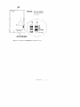
Figure 3–3. Hewlett–Packard 420–MB WinchesterDtive Jumpers (Early Model)
3-4
Configuration
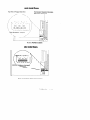
LED
Front View
L!”“H’’’’’’”w’
00
00
0
00
0000
00
J
12345678910
OFF
OFF
OFF
ON
ON
x
❑
I II
l–Write protect
2–Unit attention
3 – SDTR
4–Parity Enable
5 –Auto–Spin–Up
/“”
I
*
*
6–Sync spindle
7–Sync spindle
8–SCSI address
9 –SCSI address
10– SCSI address
“ “f
t
I
LJ
o
OFF
OFF
*
I
Front
Bottom View
* SCSI Addresses
8910
000
001
010
011
100
101
110
111
SCSI Bus
Address
0
1
2
3
4
5
6
7
g
70
Terminator
Jumpers~
m
m
B
Figure 3–4.Hewlett–Packard 420–MB Winchester Drive Jumpers (’LateModel)
Configuration
3-5
LED
NOTICE:
i
.
AO, Al, and A2 are the
SCSI ID jumpers. The
jumpers SS, TE, and WS
should be removed, and
the jumper EP should be
in place.
0
0
n
Figure 3–5. Quantum 525-MB
3-6
Configuration
WinchesterDtive Jumpers
NOTICE:
u
d
=QQ
\t7°
The first three
jumpers (1,2,
and 3) should
be removec/,
and the SCSI ID
jumpers are
jumpers 4, 5,
and 6.
.odu~
k%E::wer
o
Terminator Resistor
(Must be removed)
0
0
4
11111
000
000
m=
.
SC;,
123456
a
(second
lD\,
6
Drive)
I
~
Figure 3– 6.Seagate 525–MB and 1– GB Winchester Dtive Jumpers
Configuration
3– 7
\
LED
Front View
SCSI ID
(First Drive)
,~
o 0 00
0 0 00
0
0
00
00
00
00
0
0
~=
—
lfj
a
~
\
1234567
8910
(Second Drive)
SCSI ID
\
~=
1234567
Bj
m
8910
\
•1
1111 II
I
Ill
IT
I
Front
Bottom View
El
NOTICE:
The last three
jumpers (8, 9,
and 10) are the
SCSI ID jumpers.
Jumpers 1,2, and
7 should be
removed, and
jumpers 3, 4,5,
and 6 should be
h place.
Figure 3– 7. Hewlett–Packard 1 –GB WinchestersD]ive Jz~nzpers
(Single-Ended)
3-8
Configuration
“\ \
\
Scsl
ID
5
Scsl
ID
6
\
i
Factory–installed
/\
m
L
HI
~n~
\,.J
0000
0000
)
Terminator Resistor
Modules
(Must be removed)
\
o
n0
0
0
(
00/001000
000
~lmxl
Fid~re3 –8. Micropolis 1 – GB Winchester Dtive Jumpers
(Single-Ended)
Configuration
3– 9
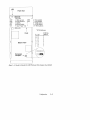
LED
Front View
Jumpers: SCSI Address
I
78910
o
0
m
6 76910
12345
0
0
00
00
m
1—
2—
3—
4—
5—
6—
3
00
00
t
1
0000
0000
MIl
0
14
m
o
0
13
00
00
12
0
0
11131
m
P
o
0
0
Q
I
1
I
I
15
m
o
0
Bottom View
2
000
000
Um
EEIIl
I
0
0
m
Front
1
3
00
00
m
I
I
4
00
00
Dill
/’1” ‘ ‘“\
00
00
11
10
00
00
EcIEl
9
000
000
EllIl
8
u
Figure 3–9. Hewlett –Packard 1 –GB WinchesterDtive Jumpers
(Fast/Wide)
3-1o
Configuration
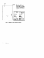
Highest
Priority
5
o
0
m
OFF Write pro;ect
OFF Unit attention
ON SDTR
ON
Parity Enable
ON
Auto–Spin–Up
OFF Sync spindle
6
Lowest
Priority
early model floppy
Top View of Floppy Disk Drive
I
Terminator Resistor Modules
(Must be removed)
1
ID Address
I
1/
{
SCSI
I
Jumpers
late model floppy
it
ID?
ID1
ID()
SCSI ID Address Jumpers
i
1!
E
Figure 3– 10. Floppy Address Jumper Settings
Configuration
3-11
Installing Additional Memory
Figure 3 – 11 shows the memory SIMM locations. Be sure to follow these guidelines:
.
The Model 735 processor board has 16–MB main memory resident (unremovable).
.
The SIMMS must be installed as pairs (two cards of the same capacity).
.
The Model 735 has six pairs of slots (numbered 1 through 6).
.
The slot pairs on the Model 735 processor board are arranged in two
connector blocks. labeled H(igh) and L(ow). The pair numbem”ngstarts in
the middle of the board, one in each connector block.
●
.
3-12
You load the boards left to right when the board is positioned as shown
in Figure 3 – 11. Startwith the highest number H slot that will be occupied
when installing the memory cards in the new processor board (if you are
installing four pairs of cards, slot 4H is the highest number H slot). You
must then fill the lower number slots in the H block. You then fill the
lower numbers in the L block, working toward the highest number L slot
that will be filled.
If you need to add SIMM cards to existing SIMMS, you will need to remove the cards already installed in the H block, and start installing the
cards at the highest number slot to be used. The cards already installed
in the L block may remain installed; just add the new cards to the higher
numbered slots. Be sure that the SIMMS remain paired properly (two
cards of the same capacity occupying the same slot number in the H and
L blocks) when you add new cards.
Configuration
NOTE:
This illustration assumes
four pairs of cards are to be
installed.
6 Pairs of
SIMM
Installation Order:
Installation Order:
Installation Order:
d
t Ca
Installing ‘One Pair
of SIMMS
Installing Ywo Pairs
of SIMMS
installing Th;ee
of SIMMS
Pairs
Fi&gre3– 11. InstallingMemory Cards
❑ 0
On
Configuration
3-13
Troubleshooting
4
This chapter provides information about isolating a failing Field Replaceable Unit
(FRU).
To troubleshoot HP Apollo workstations, you must be familiar with the HP–UX
operating system. You must be able to start and stop processes. You should also be
familiar with the Boot ROM Test Mode, ISL diagnostics, and the SupportWave
online tests.
For Series 700 systems, you note any error or status messages, and then run the
power–up boot ROM diagnostics, known as Self Test. If tfie Self Test diagnostics
fail, replace the FRU that is indicated. If the tests pass but you still suspect a problem, run the ISL dia~ostics and the SupportWave online tests. Refer to the following sections for &ore information about Self Test.
For a complete description on using ISL diagnostics and SupportWave. see the
Precision Architecture RISC HPApollo 9000 Seties 700 Diagnostics Manual.
Troubleshooting
4-1
LED Error Codes
This section contains information about the error codes displayed by the LEDs on
the system’s front panel.
If an error occurs during the power –up diaa~ostics tests, the diagnostics use the
front panel LEDs to display a code for the failing component.
Figure 4– 1 shows the location of the system unit’s front panel LEDs. There are
ni~e LEDs on the front panel. The green LED on the far right indicates that the
system is powered up. The amber LEDs labeled 1 through 8. right to left, indicate
system status and error codes.
Power
LED
Service Mode L
J
System
Status LEDs
(8 through 1)
Front (Hinged Door Opened)
Figure4–1. Front Panel LEDs
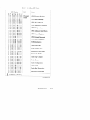
Table 4– 1 through Table 4–4 show the LED codes as they appear on the panel
display. Use these LED codes to determine the failing component.
4-Z
Troubleshooting
Table 4– 1. Seljlest LED Codes
LED Display
FRU
Error
;~:sor
cpuDia~nOseRegis’er
87654321
Dnllulnol!l
ouo~uoflu
CPU Basic Functions
CPU ALU & Branch
UUIIBOOHB
DUO
BDBOU
DUO
MIIBIIB
CPU Arithmetic Conditions
CPU Bit Operations
CPU Arithmetic Side Effects
II DIIBIIHBU
CPU Control Registers
Oollunllllfl
Iloll
DO
CPU External Interrupts
BBnnn
CPU Shadow Registers
OBMIIDI
TLB Initialization
OIIOBBOBB
Cache Data Line
DDBOIIOUB
00
Cache Address Line
BDIIDBU
nnllllon
Instruction Cache RAM
BB
Data Cache RAM
nuBnnlllln
Cache Tag Compare
DnBllnllllll
OUBOIIBB
OoBrlnll
on
II
Bill
Brlllnnn
OIIBOBIIOB
II DBOBDBU
Cache Errors
Cache Configuration
Cache Flush
Cache Byte Transaction
Instruction Cache Miss
...
...
...
..:.
.-. = LED On or Flashing
D
(Continued)
Troubleshooting
4-3
luulc v —1.
LED Display
DCLJLCSL
lJi3~
LUUt5LY
{ bUftLLfLUCU)
FRtJ
Error
:~;s”r
‘ataca’heMiss
1
87654321
Hmmlln
Cache Done
mmmHl
Memory Interface EIR
UIIUNIIUK
Memory Interface HPMC
UIUIUlllll
OIIBB
Memory Interface
DUMB
Memory Interface Invalid
Address
Memory Interface Single Bit
Error
Memory Interface Double
Bit Error
Memory Interface Diagnose
Register
Floating Point Registers
NNwlllnn
UIBBn
UIB
NIUwUlll
OOUNUB
OBOUIIIIU!I
DUllllln
Floating Point Instructions
Ul
Floating point Traps
nNlllllllBB
ON
NNIIIIB
lllln
BNIBn
BBOBOIIBB
Owlnlllln
Ollowlllll
RBOBBBBB
EISA
~zz~er
EISA Init
‘lsAmDRTest
ADDR Test Failure
EISA Pattern Test
EISA Pattern Test Failure
ROM Checksum Failure
..
.-.
.-.
.:.
..
.. = LED On or Flashing
o.:.
(Continued)
4–4
Troubleshooting
I
I
I
I
Table 4–1. Sel#est LED Codes (Continued)
LED Display.
FRU
Error
‘emo~
onboard~wwrror
87654321
mmlml
mHHHHl#
RAM SLot lH Error
Ollunnllllll
RAM Slot 2H Error
OH
RAM Slot 3H Error
BOUDHU
OBBOIIMII
II
RAM Slot 4H Error
RAM Slot 5H Error
Dnwlllnll
OEBDUMU
II
RAM Slot 6H Error
Onboard RAM (OL) Error
OBBBOOOU
RAM Slot lL Error
DBBBDOOE
RAM Slot 2L Error
nUIUlrlUl
RAM Slot 3L Error
Owlwl!l
RAM Slot 4L Error
llUIUIUln
RAM Slot 5L Error
OH
HUHOB
nEBMn
OH
Ulll
HBUHBB
DBBBBBBB
DUBKBUBO
nnnMBBBB
RAM Slot 6L Error
RAM Contlguration &
Test In Progress
No RAM Found
Non– Destructive RAM Test
RAM Configuration & Test
...
..
...
.-.
= LED On or Flashing
.-.
.-.
n.-.
(Continued)
Troubleshooting
4-5
Table 4–1. SelfiestLED Codes (Continued)
4-6
TroubleshootingL
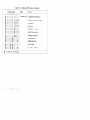
Table 4–2. PDC LED Codes
LED Display
Status
87654321
Destructive Memory Init
HmHHHlll
Non– Destructive Memory Init
Hnnnolll!ll
Bollwll!ll!
1111 Boo
Conso’ese’ection
Bon
Autoselection Failure to Find Boot Device
lwwlnll%
Honwlnn
‘aunchinglpL
BOB
OUMBB
‘OcHand’erEntered
Branching to OS TOC Handler
BUBOHOOU
Branching to OS HPMC Handler
llnwlwlE
Bnnlllllllln
MO
‘lsAsubsystemlnit
Setting Up Default EISA Config
BOMOHB
At Least One Selftest Failed (Service Mode)
lllllwlllnll
Error Reading EEPROM
Bowlrlnl!l
llloti
Boo
BOB
BOOBB
HO
HUB
‘OOtDevicese’ectiOn
Hll
‘OcOnsO1eLOcated
HBIIIOU
‘pMcHand’in@it
HPMC Due to Cache Error
BOUOI
HO
BMOBHU
Eun
Bnn
‘ne~ectedlntenu@
HPMC Due to Memory Error
MB
BOMB
HIIDU
..
.-.
.-.
.-.
.-.
.-.
.-. = LED On or Flashing
D
HPMC Due to Bus Error
Nested HPMC Detected
(Continued)
Troubleshooting
4–7
Table 4-2. PDC LED Codes (Continued)
LED Display.
Status
Error Writing EEPROM
Unable to Determine Valid Processor Speed
Processor Speed Sensing
Problem Calculating Memory Control Values
Bad Memory Hardware
.:.
..-.
... = LED On or Flashing
...
...
II
4-8
Troubleshooting
Table 4–3. ISL LED Codes
Status
LED Display
87654321
mHHHHHl
lsLExecuting*
ISL is Autobooting from the Autoexec file.
NHHHHm
ISL Cannot Find Autoexecute file.
Uollnnonn
No Console Found. ISL Autobooting.
Uonnlllllll!
Directory of utilities is too large.
OOUIIOMUB
Autoexec File is Inconsistent.
UODIIOBBU
Error Reading Autoexec File.
Unnunullll
Error Reading from Console.
Uonl!llnlll!l
Error Writing to Console.
Onllllnl!lno
Not an ISL Command or Utility.
OOUBU
MOB
olln
Bnllnn
Utility File Header Inconsistent: Invalid
System,D
“
nlln
Bnnl!B
Error Reading Utility File Header.
“
onun~nnn
Utility File Header Inconsistent: Bad Magic
Num,er
UOUBBOOH
Utility Would Overlay ISL in Memory.
“
Unllallllllll
Utility Requires More Memory
~an,sconf’gured
onll
BBrln
B
Error Reading Util;ty Into Memory.
Oonul!llun
Incorrect Checksum: Reading Utility Into
MemoV
OOIIBHHOH
System Console Needed.
“
Onnll
Internal Inconsistency: Invalid Boot Device
Class
BHBn
OOHODUUH
.....
.-.
.-.
= LED On or Flashing
...
.-.
.-.
u
Destination Memory Address of Utility is
~nva~~d
.
(Continued)
Troubleshooting
4-9
Table 4–3. LSLLED Codes (Continued)
LED Display
Status
87654321
Internal Inconsistency:pdc —cache entry
Uommll
OOBDIIOBB
Internal Inconsistency: IODC ENTRY INIT
1
Dllnnlllllln
~*~y
Internal Inconsistency* IODC
nnBllrll!loll!
Dnnllo
MBu
Ilollnn
BBll
...
.-.
.-.
...
.-.
.:. = LED On or Flashing
D
4-1o
Troubleshooting
,~,~~onso~e
-
Internal%consistency: IODC
ENTRY INIT Boot Device
Utility F~e Header Inconsistent: Bad aux id
‘adutdity
File Type
-
Table4–4. HP– UXKemel LED Codes
LED Display
Status
87654321
Kernel Loaded and Initialization Begun.
lmnHHHlo
Kernel Has Entered maino.
BHBBOOUB
Kernel Is About to Configure 1/0 System.
IBMllllolln
BBBBU
HBBBn
BOO
Hno
Kernel Is About to Mount Root File System.
Kernel Is About to Set Up Page– Out
~aemon
~~~~~oou
Kernel is”About to Start the “INIT” Process.
00000000
‘hutdOmlnprOcess*
Orlnnllnnll
‘OcDumpo
Ononll
non
OOHIIOOIIB
..
.-.
.-.
.-. = LED On or Flashing
.-.
.-.
o.-.
‘pMcDump”
Operating System Executing with Load
~ndica~or~
●
Troubleshooting
4-11
Dealing with a Boot Failure
If your usual boot device (typically a disk) is not responding as it should. you must
attempt to boot from the disk (or another boot device) by selecting it manually.
To boot a device manually, follow these steps:
1.
Turn off the power to the workstation, wait a few seconds. then turn the power back on.
20
Press
c1
Esc
.
In a few seconds, this message appears:
Terminating
selection
process.
A short time later, this message appears:
Searching
for potential
boot devices.
To terminate
search, press and hold the ESCAPE
Device
Selection
Device
Path
Device
Type
key.
and Utilities
Your workstation is now searching for devices that may hold file systems
from which it can boot HP–UX. As they are found, they appear in a list,
similar to the following sample list:
Po
PI
P2
scsi.6. O
scsi.5. O
scsi.2. O
QUANTUM
Quantum
TOSHIBA
P3
lan.123456–789abc
homebase
PD42 5S
PD425S
CD–ROM DRIVE
Thisprocess maytake several minutes. Youcanterminate thesearch atany
time bypressing
4-12
ESC .
o
Troubleshooting
When the search ends, the following list of actions appears:
b)
s)
a)
x)
Boot from specified
device
Search for bootable
devices
Enter boot administration
mode
Exit and continue boot sequence
?)
Help
Select
from
menu:
Ifnodiskdevices are listed. thenyour workstaton isfailing tocommunicate
with its disks. Recheck the SCSI connections andtryagain.
Ifnodevicesarelisted
at all. alternative methodsforbootinq b shouldbetried,
suchasconnecting anexternal CD –ROMdrive.
s.
Ifthesearch locates adisk, attempt to boot fromitby entering the b(boot)
command and a device selection number from the list. For example. if a SCSI
disk is listed as item PO(as in the example list above), enter the
following:
Select
from menu:
b PO [=)
After a few seconds, the boot messages begin to appear on the screen. You
may hear sounds coming from the disk drive and see a sequence of changing
patterns on the LED display.
a.
If your workstation still fails to boot, there is either something wrong with
the file system or with the hardware.
Boot Administration
Environment
The Boot Console User Interface provides an “interactive” environment after the
power– on sequence. The Boot Console User Interface must be invoked before
the Initial Program Loader (IPL) routine. Users do not have to interact with the
interface when the AUTOSELECT mode is enabled.
The Boot Console User Interface executes user–entered commands that perform
the following functions:
Display the state of Autoselect mode using the AUTO command.
Set the state of the Autoselect mode using the AUTOSELECT command
with either the ON/ OFF option.
Boot from the primary or alternate boot path or any specified path using
the BOOT command.
Set or display the real–time clock value using
Gthe DATE command.
Troubleshooting
4–13
.
Return to previous menu using the EXIT command.
●
Set or display the Fastsize value (amount of memory initialized during
boot) using the FASTSIZE command.
.
Display a menu of commands using the HELP command or a description
of any command as an option to the HELP command.
.
Display the model number. version numbers, and jumper settings on the
System card using the INFO command.
.
Display the current LAN STATION ADDRESS value in stable storage
using the LAN_ADDR command. Must use SS_CONFIG to set this value.
.
Display the current FDDI STATION ADDRESS value in stable storage
using the FDDI_ADDR command. Must use SS_CONFIG to set this
value.
●
Select an operating system for the next boot attempt using the OS command.
.
Set or display the current values for the console, keyboard, primary, or
alternate boot paths using the PATH command.
e Display the most recent HPMC~or TOC error information logged into
Stable Storage using the PIM INFO command.
.
Reset the System Unit using the RESET command.
.
Search for possible boot devices using the SEARCH command.
.
Display/Set secure boot mode or the ability to interact with the console
device within the first 10 seconds before boot device selection is disabled
using the SECURE command.
.
Display the results of the previous search command using the SHOW
command.
Syntaxchecking is performed for any supported commands. Error status is displayed on the console along with any relevant information.
Stable Storage
Stable Storage is non–volatile memory associated with each PA– RISC processor
module. Stable storage is used by the processor (CPU) to store device path information, the state of the boot flags, HPMC error reformation, and operating system
initialization data.
4-14
Troubleshooting
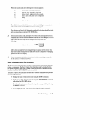
Boot Command Notations
The BOOT command supports the following three notations:
●
Mnemonic
●
PA- RISC 1/0
●
Path number
Type help scsi or help Ian for more information on the boot path parameters.
Here are examples of mnemonic notation:
●
BOOT
c1
FIETIJFINwith “no parameters” selects the primary boot path in
stable storage.
●
BOOT with the ALTERNATE or ALT parameter selects the alternate
boot path in stable storage.
Here is an example of path number notation:
●
BOOT PI
c1
R=URN attempts to boot from the second path indicated by
the SEARCH command.
Supported Boot Paths
SCSI devices are bootable when connected to the SCSI port on the System card.
Diskless workstations can only boot from the LAN port on the System card.
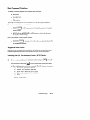
Invoking the ISL Environment from a SCSI Device
D
Power–on (or cycle the power) the System Unit and press ESC to stop the
boot process and then press Esc to Stop the selection process and invoke
o
the Boot Administration mode (environment). The following screen appears:
b)
s)
a)
x)
?)
Boot from specified
Search for bootable
device
devices
Enter Boot Administration
mode
Exit and continue boot sequence
Help
Select
from menu:
_
Troubleshooting
4–15
z.
c1
Types
RmURN to search for devices with the ISL program and hpux (load-
er) utility in their LIF directory. The following screen appears:
Searching
for bootable
devices.
To terminate
search, press and hold
Device
Device
Selection
Path
scsi.6.O
Po
b)
s)
a)
x)
?)
the ESCAPE
key.
Device
QUANTUM
Type
PD425S
Boot from specified
device
Search for bootable
devices
Enter Boot Administration
mode
Exit and continue boot sequence
Help
Select
from menu:
—
u
TypebpOipl
R~URN toinvoketheISL
environmentfrom the210MB
Quantum disk. The following messages, the ISL banner, and the ISL prompt
are displayed:
Trying scsi.6.O
Boot path initialized.
Attempting
to load IPL.
Hard
booted.
ISL Revision
ISL>
Q.
Typels
27,
1990
C)*CI
R~lJRN or hstf R~URN to review the state ofthe ISL boot flags,
andthefilesin
Typehpuxbootdisc(;O)/hp-ux
from thescsi device.
4-16
March
—
theISLcommands.
device.
s.
A.00.09
Troubleshooting
theLIFdirectory
c1
onthescsi
R~URf’J toloadtheHP–UXenvironment
ISL Environment
The ISL environment provides the means to load the operating system (HP–UX)
environment. The ISL environment also provides an offline platform to execute
diagnostic and utility programs from a boot device when HP–UX does not load.
The ISL program is the first program loaded into main memory from an external
media (L~~ disk. or tape) and launched by the initial program loader
(IPL) routine during the Boot Administration environment.
The ISL environment provides the following capabilities:
.
Execute user– entered commands to modify boot device paths and boot
options in stable storage.
.
Run off–line diagnostic programs (MULTIDIAG, IOMAP).
.
Provide automatic booting of the HP – UX 0/S after power—on or reset.
The ISL program provides a standalone environment for loading offline diagnostic
and utility programs from the LIF directory. The ISL program also provides user
commands to configure the boot parameters into Stable Storage.
ISL User Commands
There are several commands available in the ISL environment that allow a user to
obtain information about the boot characteristics of the system or to modify these
characteristics.
●
●
display – displays the boot and console paths in Stable Storage and to
determine the current setting of the ISL Boot Flags.
&
PrimPath _ modifies the primary boot path entry in Stable Storage. The
entry in Stable Storage for the primary boot device begins at byte address
Oand ends at byte address51.
●
altpath – modifies the alternate boot path entry in Stable Storage. The
entry for the alternate boot device begins at byte address 128 and ends at
159.
●
conspath – modifies the console path entry in Stable Storage. The entry
in Stable Storage for the console device begins at byte address 96 and
ends at byte address 127. The entry for the keyboard and mouse devices
begins at byte address 160 and ends at 191.
●
listautofl or lsautofl – lists the contents of the (HP–UX)
.
support – boots the Support Tape from the boot device.
●
readss – displays 4 bytes (one word) from Stable Storage. The readss
command requires a decimal number between Oand 255 to address four
bytes in Stable Storage.
autoboot file.
Troubleshooting
4-17
/’
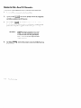
Running the Disk– Based ISL Diagnostics
To run the ISL–based diagnostics in the LIF directory on the System Disk:
1.
Invoke the ISL environment from the System Disk.
z.
Type 1s(or Iistf)
u
after the ISL prompt to list the ISL diagnostics
c1
after the ISL prompt to invoke the multidiag test
RETURN
and utilities available in the LIF directory.
s.
Type multidiag
RETURN
from the System Disk. (This test takes several minutes to complete and appears to be in a loop when a graphics monitor is the system console.)
NOTICE:
A.
c1
Type iomap R~URN after the ISL prompt to invoke the IOMAP test from
the System Disk.
4-18
multidiag contains a loopback test for audio
testing. To run the loopback test, you need
to attach the audio test cable (part number
46081 –61601) to the audio input and audio
output connectors.
Troubleshooting
Verifying the System Operation with SupportWave
HP–UX Version 9.0 uses a diagnostics product called SupportWave. To verify
your system operation, SupportWave contains the Support Tools Manager.
You can access the Support Tools Manager while in a terminal window: if you are
using HP– WE as your interface. you can also access the Support Tools Manager
through the sys_admin directory.
Three interfaces are available with the Support Tools Manager: a command line
interface (accessed through the cstm command), a menu interface (accessed
through the mstm command). and the graphical users interface (accessed through
the xstm command)
To invoke the command line interface, type the following in a terminal window:
# c1
cstm RmURN
The following screen appears:
***************
******
******
***************
System
in progress
***************
***************
****
******
******
SUPPORT TOOLS MANAGER
******
******
******
******
Command Line Interface
******
******
******
******
Version
A.OO .12
******
******
******
******
B2478-1OOO2
Part Number
******
******
******
******
(C ) Copyright
Hewlett Packard Co. 1991,1992
******
******
All Rights Reserved
******
******
***************
***************
*************** *************** ****
mapping
. . .
C STM>
Atthe CSTM>prompt, youcanenter several commands. Toseewhat commands
are available, type the help command.
To verify the system operation, type the following:
c1
CSTM > verify all R~URN
The following messages appear:
Verification
Verification
Verification
Verification
Verification
Verification
has
has
has
has
has
has
started
started
started
started
started
started
on
on
on
on
on
on
device
device
device
device
device
device
(CPU).
(FPU).
(0/0/0).
(2/0/1.5.0).
(2/0/1.6.0).
(2/0/2).
Troubleshooting
4-19
CSTM>Message
from (0/0/0):
This graphics test displays
a number of graphics
images on the
If an X server is
screen of the graphics device being tested.
not currently
running on that display,
X Windows will be started
The Starbase
shared liand run for the duration
of the test.
brary (/usr/lib/libsb.sl)
should be present to run this test.
CAUTION: This test will
is modified or overlaid
fail if any portion
in any way.
of the test window
NOTE : If a WE
login screen is currently
displayed
on the monitor, the test will wait until someone logs in the Hl? VUE on the
graphics monitor to release the lock.
The test stops if the
Screen Saver times out, it runs again once the Screen is activated.
WARNING:
(Type
Do not
run this
‘R’ for Ready,
exerciser
Type
When~ou seethepromptshown
A
with
‘S’ for Skip)
above,typer
“A
any other
operation.
[R] >>
R~URN
m.
\
●
Verification
of
(2/0/1.5.0)
complete.
Result
status
– (Success).
Verification
of
(2/0/1.6.0)
complete.
Result
status
– (Success).
Verification
Verification
Verification
Verification
of
of
of
of
(CPU) complete.
Result status – (Success).
(FPU) complete.
Result status – (Success).
(2/0/2) complete.
Result status – (Success).
(0/0/0) complete.
Result status – (Success).
c1
Typing RETURNat this point returnsthe CSTM> prompt. Nowtypethefollow-
ing:
Ifanytestsfail, further diagnosis isnecessary.
❑
❑
4-~()
Troubleshooting
0
0
,.
Field Replaceable Units
5
This chapter provides a list of the Field replaceable units (FRUS) and illustrations
for the FRU removal and replacement.
The tools required for FRU removal and replacement areas follows:
#1 Phillips screwdriver with 100–mm (4–in.) blade
Light–duty,
flat –tipped screwdriver with
150–mm (6–in.) blade
Needlenose pliers
WARNING:
For each of the removal procedures in this
chapter. you must shut down the operating
system, power off the system. and unplug the
power cord from the wall.
NOTICE:
To maintain FCC/EMI compliance, verify
that all covers are replaced and that all
screws are properly seated.
Field Replaceable Units
5-1
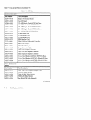
Table 5 – 1 lists all the FRUS for the Model 735.
Table 5-1.
FRU List
EXCHANGE PARTS
Part Number
A2095 –69510
Part Description
Model 735 Processor Board
A2095 –69033
Core 1/0 Board
A2084-69001
525 –MB Single–Ended SCSI Disk Drive
A2084-69002
A1094–69O12
1.O–GB Single–Ended
SCSI Disk Drive
&
420–MB Single–Ended SCSI Disk Drive
A1094–69OH
21O–MB Single–Ended SCSI Disk Drive
A2095 –69001
1.O–GB Fast/Wide SCSI Disk Drive
A1094–69521
8–MB SIMM Card
A2512-69001
16–MB SIMM Card
A2517-69001
32–MB SIMM Card
A1094–69531
EISA Interface Card
25525 –69001
EISA SCSI Fast, Differential Controller
25567 –69(J)1
EISA LAN Adapter
25560–69001”
EISA HP–IB Adapter
A1094–69OO7
Floppy Drive (1.44 MB)
A1659–69001
CRX Color Graphics Controller
A1436–69571
CRX– 24 Color Graphics Controller
A1924–69001
GRX Grayscale Graphics Controller
A2094-69001
19–in. Color Monitor (A2094A-SONY)
N. Hem.
A1097–69OO3
19–in. Color Monitor (A1097A.C–Hitachi)
N. Hem.
A1097–69OO4
19–in. Color Monitor (A1097B.D–Hitachi)
S. Hem.
A2088 –69001
19–in. Grayscale Monitor @2088A)
NON–EXCHANGE
PARTS
Part Number
Part Description
AM54-69571
CRX– 242 Color Graphics Daughter Card
A2095-66584
LAN AUI Slider Module
A2095-6~586
ThinLAN BNC Slider Module
A2095 –66580
FDDI LAN Slider Module
A2095-62016
Fast. Wide SCSI Cable (Internal)
(Continued)
5-Z
Field Replaceable Units
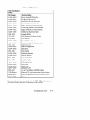
Table 5–1. FRUList (Cont.)
NON-EXCHANGE
PARTS
Part Number
Part Description
A1094–6OO1O
Single–Ended SCSI Disk Tray
A2095-00016
Fast/Wide SCSI Disk Tray
A1658–62018
Fast/Wide SCSI Cable (External)
A1658–62024
SCSI Terminator for Fast/Wide
A1094–616O4
Single–Ended SCSI Cable (Internal)
A1094–616O6
SCSI Floppy Extender Cable (Internal)
A1094–616O1
Single–Ended SCSI Cable (External)
A1094–616O5
SCSI Device Tray Power Cable
1420–0314
Calendar Battery
1252–3932
SCSI Terminator for Single–Ended
2110–0520
LAN AUI Fuse
A2095 –84002
Model 735 Front Label
A1094–6OOO1
Chassis Assembly (Less plastic covers)
5041–2452
Plastic Top Cover
A1094–6OOO3
Bezel for Floppy Drive
A1094–6OOO2
Blank Bezel
0950–2081
Power Supply
A1094–665OO
Backplane Assembly
A1094–62O22
Deskside Pedestal
5061–6572
Large Cooling Fan
5061–6573
Small Cooling Fan
A1094–6654O
LED Display Card
A1094–61O62
LED Cable
A1094–66541
Switch Card
A1094–616O3
Backplane Cable
2090–0315
19–in. Color Monitor (A2094B) S. Hem.
C1429B #Axx
Keyboard, PC–style (must supply localized option)
46021B #Axx
Keyboard, HP–UX
46060–60202
Mouse
(must supply localized option)
For service information and part numbers for the CRX– 482 graphics option, see
lIPA2091A Graphics Processor CE Handbook (A2091 –90039).
Field Replaceable Units
5-3
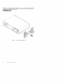
Figure 5– 1 through Figure 5– 15 illustrate how to remove the individual FRUS.
Observe the notices and prerequisites for removing each FRU. Replacement is
the reverse of removal, unless noted.
Pedestal Feet
Figure.5– 1. Removing Pedestal Feet
5-4
Field Replaceable Units
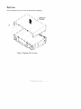
Top Cover
Before removing the top cover. remove the pedestal feet (if installed).
.
IF’e“
Figure 5–2. Removing Top Cover Screws
Field Replaceable Units
5-5
\
Ii’
e
,/
6?’
/
/
r’
I
I /
I/ /
Figure 5–3. Lifiing
Top Cover
.
5-6
Field Replaceable Units
-,,’
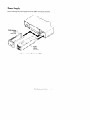
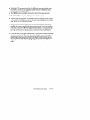
Power Supply
Before removing the power supply remove the EISA card adapter assembly.
Figure 5–4. Removing the Power Supply
Field Replaceable Units
5-7
>
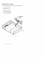
Backplane/Fan Assembly
Before removing the backplane/fan assembly, perform the following steps:
. Remove the pedestal feet.
. Remove the top cover.
●
Remove the power supply.
●
Remove the graphics card.
. Remove the core 1/0 card.
.
Remove the processor cad.
Figure 5–5. Backplane/FanRemoval
5-8
Field Replaceable Units
f
R?
Larqe
Figure 5– 6. Removing the Fans and Backplane AssenzbZy
Field Replaceable Units
5-9
. .
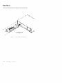
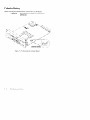
Disk Drives
Before removing the disk drives disconnect external SCSI cable.
C@”
Figure 5– 7. Removing the FirstDisk Drive
5-1o
Field Replaceable Units
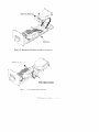
NT’
Figure 5–8. Mounting the Disk Drive Assembly on the Disk Tray
SCSI Cable Connector
ector
Figure 5–9. Connecting Cables to the Disk
Field Replaceable Units
5-11
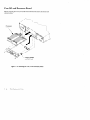
Core 1/0 and Processor Board
Before removing the Core 1/0 and Processor Boards, disconnect all internal and
external cables.
/’-1..
v
and Bulkhead
Figure 5– 10. Removing the Core 1/0 and Processor Boards
5-12
Field Replaceable Units
SCSI Speed
Jum~ers
Figure 5– 11.Component Locations
System EEPROM
When replacing a processor board, remove the EEPROM from the failed processor board and install it in the new/exchange processor board, as shown in
Figure 5 – 11. Remove the EEPROM from the new processor and place it into the
de~ectiveprocessor. (This is required for the board test/repair process.)
NOTICE:
The EEPROM on the processor board stores the 1/0
configuration information. To retain this information
when you replace a processor board. move the original EEPROM to the new processor board.
CAUTION:
Use an anti– static strap to prevent electrostatic damage to the EEPROM. Electrostatic damage can destroy the EEPROM or erase configuration information from the EEPROM.
Field Replaceable Units
5–13
Memory
Before removing the memory, perform the following steps:
. Remove the Core 1/0 Board.
.
Remove the Processor Board.
Figure 5– 12. Removing Mer.no~ Boards
5-14
Field Replaceable Units
. The Model 735 processor board has 16—MB main memory resident (unremovable). Therefore. the upgraded system will have 16 MB more main
memory than the original system.
.
The SIMMS must be installed as pairs (two cards of the same capacity).
.
The Model 735 has six pairs of slots (numbered 1 through 6).
. The slot pairs on the Model 735 processor board are arranged in two connector blocks, labeled H(igh) and L(ow). The pair numbering starts in the middle
of the board, one in each connector block.
●
You load the boards left to right when the board is positioned as shown in
Chapter 3. Startwith the highest number H slot that will be occupied when
installing the memory cards in the new processor board (if you are installing
four pan-sof cards, slot 4H is the highest number H slot). You must then fill
the lower number slots in the H block. You then fill the lower numbers in
the L block, working toward the highest number L slot that will be filled.
.
If you later need to add more SIMM cards, you will need to remove the cards
already installed in the H block, and start installing the cards at the highest
number slot to be used. The cards already installed in the L block may remain installed; just add the new cards to the higher numbered slots. Be sure
that the SIMMS remain paired properly (two cards of the same capacity occupying the salineslot number in the H and L blocks) when you add new
cards.
Field Replaceable Units
5–15
Calendar Battery
Before removing the calendar battery. remove the Core 1/0 Board.
CAUTION:
Discard battery according to manufacturer’s
instructions.
Fibg.we5– 13. Removing the Calendar Battery
5-16
Field Replaceable Units
. .
LAN Slider Module
Before removing the LAN slider module, remove the Core 1/0 Board.
Fi&qre5– 14. LAN SliderModule Removal
Field Replaceable Units
5-17
.-
.
Graphics Board
Before removing the Graphics Board, disconnect cables.
5-18
Field Replaceable Units
.>
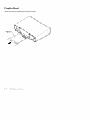
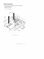
Front Control Panel
Before removing the front control panel, perform the following steps:
. Remove the pedestal feet.
.
Remove the top cover.
.
Remove the disk tray.
Figure 5– 15. Removing the Front Control Panel
❑
❑
0
0
Field Replaceable Units
5-19
‘,,
.
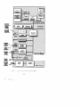
Diagrams
Figure 6 – 1 shows the system block diagram.
Diagrams
6-1
..........
...........
..........
...........
..........
...........
..........
...........
..........
m--~
....
...
-.+..
......
.......
....
.....
....
.....
.. a Video
.....
....
.......
......
.......
......
.......
......
......
.........
........
........ .
r........
Momor
....................
...................
Iiiiiir
il
Keyboaru
“::==:2:
. ....
z..-....L Graphics
-----
HP-HIL
...................
..................
......
.........
.................
..........
....
........
........
......
.........
..........
.........
..........
....._
..........
.........
..........
.........
k-l
..................
.................
.................
IE ..................
.................
..................
.................
d
71!!!%4
.
. . . . .
. .
. . .. . .. .
. . .
-
..
:::::::
. . .
2ieKmi
..................
.................
.................
..................
;@.-.:
....
....
....
....
.....
....
.... .-- .....
...
....
-:
-:-:.:
....
.....-.....
... ..........
....
!!)!)!4
~#gJ
.......
3Mliwti&
..................
.................
Audio
System
Cnnnaet
-us
as l-vu
... .. . . .. . . . .. . . . . . .. . . .. . . . . . . . . . . .
..... .... .... . ...... .. . . ... ..... ......... . . . . . . . . . . . . . . . . . . . . .. . . . . . . . . . .. . . . . . . . . . .
. .
. .
. . .
.
. . .
.
. .
. .
. . . .
. . . . . --------------------
. -. . . . . . . . . . . . . . . . . . --------------------
...........................
...........................
...........................
...........................
...........................
...........................
..........................
...........................
............
..............
..........................
-:-:-:-:.:-:-:.:-:.:-:-:.:-;.;-:.;.:.:.:.:.:.:.:.:.:.:
IE--------------”
..................
...................
..................
...................
..................
...................
..................
‘---”-””1
. . . . . . . . .. . .. . . . . . . . . . . . . . . . . .
II
I
.::::~:~:~~:::~~:~:~~:~::~~<~:~:<<<:-:~~;
.......
..................
......-----------....----.---------------------.................
.........
......
.....
......
.......
.......
.......
..........
.........
..........
‘“’”-’
............
............
...........................
.......................................
....................................
..
.......................................
.......................................
.......................................
:$~:$z:::$:z::zz:zz::
.........
..........-------------------.........................----------.-.........-.-...........
.........................
.............
...............
.........
..........
.........
..........
.........
..........
.........
..........
..........
:<::1:1<~............
........ .
z:g$$z:%as~z:;
..........
.......................... ............
.-..--.~--.
..........................................................................................................................
Figure 6– 1. System UnitFunctional Block Diagram
❑
❑
6–2
...........
.................
........
.....................
...........................
...........................
..........................
...........................
...........................
...........................
...........................
...........................
...........................
...........................
...........................
...........................
..........................I
lee””--------”-”--”---””---........
........
........
........
.........
........
.........
........
.......
........
.........
........
.........
li!r-
...... ...................................
..............................................
‘:::x:’::;’:~~:>-””””
. . . . . . . . . . . .. .. . . . . .
...................
. . . . . . . .. . .. . . . . . ..-.-.-.:::;;::s<:<;<:>-:2::w.::-;":+-;-:-:-:-;:-;-;-;-;";-:"::
. . .. . . . .---. . . . .. . .
;:::.,.:.->&#&l
.
.
.
. . .
. . . .
..
. . . .. . . .
.
. . . . .
........
.......
. - .-.. :
.....
.....
......
EiEz$eii@8FE~$
..f ....
........
.----------.....................
......---.
.-.-.--..--.-:
--------..........
...
......
...............
....-.
............
. ........-.-.
.-.
-.-.--.=
-------.........
.....
......
....................
.....
.......
......
:;:-.-j*
.......................
...........
..............
............
.................................................
>~~:~:~,<..
...............................................
...............
......................
...................................
. . ...........
...........
.........i
.........
.
.......
.......-----------..........-..............-----......
..... ................
.....
.....
.....
.....
.....
Diagrams
lcl
ID
. .
Reference
7
This chapter provides part numbers and titles to documents which can be used for
reference.
Installation
A2095-90000
Manual
HP Apollo 9000 Series 700 Model 735
Hardware Installation Guide
Service Manuals
A2095 –90002”
A2091 –90039
09704–90041
B2355 – 9003
5960–1511
HP Apollo 9000 Series 700 Model 735
Customer Eng. Service Handbook
HP A2091A Graphics Processor CE Handbook
Precision Architecture RISC: HP APO11O
9000 Series 700
1
Diagnostic Manual
System Administrator’s Task Manual HP Apollo 9000 Series 700
Servicing Hewlett –Packard Workstation Monitors
Reference Manuals
A2095 –90001
A2512-60000
A2563 –90000
A1984–90001
A2665 –90000
HP Apollo 9000 Series 700 Model 735 Owner’s Guide
Installing Additional Memory in the lIP Apollo 9000 Series 700
Model 735
SCSI Disk Drive Installation Guide
SCSI Floppy Disk Drive Installation Guide
FDDI Upgrade
Instructions
G
❑
❑
a
o
Reference
7– 1
Service Notes
Place service notes here.
❑
o
❑ 0
Service Notes
8-1
B
block diagram, 6–2
boot admin mode, 4– 13
boot command notations, 4– 15
boot failure, 4– 12
boot paths, 4– 15
CPU removal, 5 – 12
D
diagnostics, 4– 1
boot ROM, 4–1
diagrams, block diagram, 6–2
documentation,
reference, 7– 1
boot ROM diagnostics, 4– 1
c
calendar battery removal, 5 – 16
configuration
FRU, 3– 1
mass storage, 3 – 1
memory, 3 – 12
connectors
monitor, 1– 13
system unit, 1–7
ac, 1–7
audio, 1– 10
graphics, 1– 12
HP–HIL, 1–8
network, 1–8
parallel, 1–8
RS–232, 1–9
serial, 1–9
Controls
monitor, 1– 13
system unit, 1–3
CPU components locations,
5–13
E
EEPROM, data storage, 5 – 13
environmental
2–1
specifications,
F
fan removal, 5 –9
first disk removal, 5 – 10
front control panel removal,
5–19
FRU configuration, 3 – 1
FRU parts list, 5 –2
FRU removal
calendar battery, 5 – 16
CPU, 5 –12
fan, 5 –9
first disk, 5 – 10
front control panel, 5 – 19
memory, 5 – 14
pedestal feet, 5 –4
power supply, 5 –7
Index–
1
top cover, 5 –5
N
network, connector, 1–8
I
installing memory cards, 3 – 13
P
part numbers, 5 –2
ISL commands, 4– 17
pedestal feet removal, 5 –4
ISL diagnostics, 4– 18
power supply removal, 5 –7
ISL environment, 4– 15
preventive maintenance,
2–2
R
J
jumpers, SCSI ID
HP Winchester drive, 3 –8,
3–lo
Micropolis drive, 3 –9
Quantum drive, 3 –6
Seagate drive, 3 –7
reference documentation,
regulatory requirements,
7– 1
2–2
RS–232
connector, 1–9
pinout, 1–9
s
L
SCSI devices
default IDs, 3 –2
terminators, 3 – 1
LED error codes, 4–2
LEDs, 4–2
system unit, 1–5
M
mass storage configuration,
memory configuration,
3 – 12
memory removal, 5 – 14
monitor
connectors, 1– 13
controls, 1– 13
Index–2
3– 1
SCSI IDs, 3 –2
jumpers
floppy drive, 3 – 11
HP Winchester drive, 3 –4,
3–5,3–8,3–10
Micropolis drive, 3 –9
Quantum drive, 3–3, 3–6
Seagate drive, 3 –7
serial
connector, 1–9
pinout, 1–9
service notes, 8 – 1
specifications, environmental,
2–1
stable storage, 4– 14
toubleshooting, boot faliure,
4–12
-
SupportWave diagnostics, 4– 19
troubleshooting, 4– 1
ISL commands, 4– 17
ISL diagnostics, 4– 18
ISL environment, 4– 15
LED codes, 4–2’
SupportWave diagnostics,
4–19
T
terminators, 3 – 1
top cover removal, 5 –5
❑ 0
❑ 0
Index–3
Documents
for
The
following
to
print
the
Rule(s)
Character(s)
Character(s)
on
this
items
page
printer
should
are
outside
incorrectly:
page
on
page
O of
-job.
84
of
job.
on
page
86
job.
of
the
have
1/4”
printable
margins
region
on
all
sides.
and
may
cause
the
printer