1
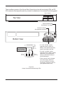
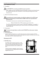
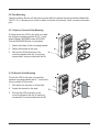
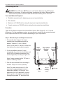
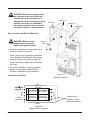
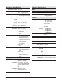
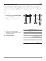
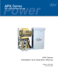
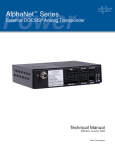
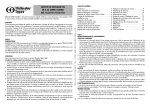
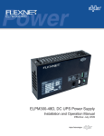
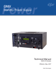
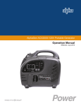
Novus Micro Secure 100 Uninterruptible Power Supply Operator’s Manual 017-220-B0 Rev. 01 / 07 Alpha Technologies Power Alpha Technologies ® Operator’s Manual Novus Micro Secure 100 Uninterruptible Power Supplies From Alpha Technologies (www.alpha.com) 017-220-B0 Rev. 01 / 07 Save This Manual: It contains important installation and operating instructions. Keep it in a safe place. Table of Contents The emergency shutdown procedure is on the inside rear cover 1 Safety Checklists......................................... 1 1.1 UPS Safety Checklist............................. 1 1.2 Battery Safety Checklist......................... 2 2 Unpacking and Inspection Checklist......... 3 3 The Novus Micro Secure............................ 4 4 Site Preparation Checklist.......................... 6 5 Mounting the UPS........................................ 6 5.1 Wall Mounting........................................ 6 5.2 Pole Mounting........................................ 7 6 Connecting the UPS.................................... 8 7 Powering On the UPS................................ 10 Specifications............................................... 11 Appendix....................................................... 12 A1 Connecting the RS-232 Port.................. 13 A2 Using the Main Menu.............................. 14 A3 Operating the UPS.................................. 18 A4 Programming the Dry Contacts and the Clock........................................................ 19 A5 Accessing the 100-Event Log................ 21 A6 Installing and Using the Novus User Software................................................... 22 Warranty........................................................ 27 Index.............................................................. 28 DANGER Risk of Electrical Shock To reduce the risk of electrical shock and to ensure the safe operation of the Novus Micro Secure 100, the symbols below are used throughout this manual. Where they appear, only qualified personnel should carry out these instructions. A dangerous voltage exists in this area. Use extreme caution at all times. Attention: Important operating instructions. Follow them exactly. 1 Safety Checklists 1.1 UPS Safety Checklist This Uninterruptible Power Supply (UPS) is to be installed by people trained in the safe use of high-energy power supplies and their batteries. Also assumed is knowledge of the local electrical code(s) and their safe application. DANGER: NEVER let water from rain, a hose, tap or a sprinkler’s output, road splash or other water sources enter the UPS to prevent accidental shorts, shocks or electrocutions. DANGER: This unit does NOT have an on/off switch. Whenever it is connected to line or battery power, power is present at the output. Use extreme caution at all times. Do not work alone under hazardous conditions. Read this manual. If you have any questions about safe installation, operation or maintenance, contact Alpha Technologies’s customer service department. Carefully unpack the components. Report any shipping or other damage at once. Always assume electrical connections or conductors are live. Turn off all circuit breakers and double-check with a voltmeter before performing installation or maintenance. Before installation, verify the input voltage and current requirements of the load are met by the UPS’s output (See specifications). Verify the line voltage and current meet the UPS’s input requirements. Place a warning label on the utility panel to tell emergency personnel a UPS is installed. Use proper lifting techniques when lifting or moving the UPS or its components. This UPS has more than one live circuit. AC power may be present at the outputs even if the UPS is disconnected from line or battery power. This UPS can be operated to a maximum operating temperature of 50°C. Also see the specifications section for temperature ratings. At high ambient temperature conditions, the UPS’s surface can be very hot to the touch. There is a Lithium battery inside the UPS. There is a danger of an explosion if it is incorrectly replaced. Replace it only with the same type or an equivalent battery as recommended by the manufacturer. Dispose of the old battery as instructed by the manufacturer. Doc# 017-220-B0 Rev. 01 / 07 Novus Micro Secure 100 Operator’s Manual 1.2 Battery Safety Checklist Battery Emergency Procedures If electrolyte splashes on your skin, immediately wash the affected area with water. If electrolyte gets into your eyes, wash them for at least 10 minutes with clean running water or a special neutralizing eye wash solution. Seek medical attention at once. Neutralize spilled electrolyte with special neutralizing solutions in a “spill kit” or a solution of 1 lb. (0.45 kg) of baking soda (bicarbonate of soda) in 1 gallon (3.9 L.) of water. Battery installation and servicing should be done or supervised by personnel knowledgeable about batteries and the required precautions. Always replace batteries with the same type, numbers, and ratings. Never install old or untested batteries. One sealed lead-acid battery is rated to a maximum voltage of 12VDC. CAUTION: Never dispose of batteries in a fire. The batteries may explode. Follow the manufacturer’s directions for safe battery disposal. CAUTION: Never open or damage the batteries. Released electrolyte is harmful to the skin and eyes. It may be toxic and hazardous to the environment. CAUTION: A battery can present a risk of electrical shock and high short-circuit current. The following precautions should be observed when working on batteries: • Remove watches, rings, or other metal objects. • Use tools with insulated handles. • Wear rubber gloves and boots. • Do not lay tools or metal parts on top of batteries. • Disconnect charging source prior to connecting or disconnecting battery terminals. • Determine if the battery is inadvertently grounded. If inadvertently grounded, remove source from ground. Contact with any part of a grounded battery can result in electrical shock. The likelihood of such shock can be reduced if such grounds are removed during installation and maintenance (applicable to equipment and remote battery supplies not having a grounded supply circuit). Never let live battery wires touch the UPS, the enclosure or any other metal objects. This can cause a fire or explosion. Lead-acid batteries can release Hydrogen gas. Never expose the UPS or enclosure to open flames or sparks to prevent a fire or explosion. Inspect the batteries once a year for signs of cracks, leaks or swells. Replace as needed. If you have batteries in storage, charge them at least once every three months for optimum performance and to extend their lifetime. Doc# 017-220-B0 Rev. 01 / 07 2 Unpacking and Inspection Checklist If items are missing or damaged, contact Alpha Technologies and the shipping company at once. Most shippers have a short claim period. Carefully remove the UPS from the shipping container. Inspect the contents and make sure the following items are included: 1 Micro Secure UPS. 1 Micro Secure Operator’s Manual. 4 Phillips-head wood screws. 2 or 4 batteries as ordered. 1 battery fuse (Standard 30A automotive fuse). Any ordered options. Save The Shipping Container To return the Micro Secure for servicing, pack it in the original shipping container. Alpha Technologies is not responsible for any damages caused by improper packaging of returned products. Read This Manual Before installation become familiar with the Novus Micro Secure by reviewing the procedures and drawings in this manual. If you have any questions about the safe installation, operation or maintenance of this UPS, contact Alpha’s customer service department at www.alpha.com. Doc# 017-220-B0 Rev. 01 / 07 Novus Micro Secure 100 Operator’s Manual 3 The Novus Micro Secure Batteries Front Cover has 2 LEDs; green and red (See Section 7 for details) Battery Fuse (30A standard automotive fuse) Input Circuit Breaker NEMA 5-15P Plug (120V) (Input power cable not provided for 230V application) Output Connector Figure 3.1 Novus Micro Secure - Cable Version Batteries Battery Fuse (30A standard automotive fuse) Optional, factory-installed Ethernet card Input Circuit Breaker Input Terminal Block Output Terminal Block RS-232 connector, LED’s and dry contacts (See Figure 3.3) Figure 3.2 Novus Micro Secure - Surveillance Version Doc# 017-220-B0 Rev. 01 / 07 The surveillance version of the Novus Micro Secure has a bar with monitoring LEDs, an RS232 connector (See Appendix) and dry contacts for attachment of an external monitoring panel. Dry Contacts Top View C1 1 NO 2 C C2 3 NC 4 NO 5 C 6 NC Green and Red LEDs See Section 7 for details RS-232 Connector See appendix for details Bottom View Microprocessor UPS Interior The dry contacts have a maximum rating of 1A at 250V. Normally Closed (NC) Normally Open (NO) Common (C) • C1 is the “On Batt” contact, triggered when the UPS is in Battery mode and backup battery power is provided to the load. • C2 is the “Low Batt” contact, triggered when the battery voltage falls below a pre-programmed setting to indicate the battery is almost discharged. • These contacts can be changed from these factory defaults to suit your conditions if you have connected a computer to the unit (See Appendix Section A4). Figure 3.3 Output Connectors And Monitoring LEDs Doc# 017-220-B0 Rev. 01 / 07 Novus Micro Secure 100 Operator’s Manual 4 Site Preparation Checklist Grounding The UPS MUST be correctly grounded for proper operation. Older facilities may have inadequate electrical grounding. Inspection must be performed by a qualified electrician before installation to ensure that grounding meets the local electrical code. Branch Circuit Breaker Protection To provide branch circuit protection, the utility line attached to the UPS’s input MUST be protected by a circuit breaker certified for this use as per the local electrical code. The breaker’s minimum size is calculated by the following formula: Minimum Breaker Size= UPS’s maximum input current / 0.8 The UPS’s maximum input current is read off of the UPS’s nameplate. For example, if the nameplate gives the maximum input current as 20A, the circuit breaker should be rated at least 25A.. Disconnects The input and output lines to and from the UPS MUST have disconnect devices attached. Site Requirements Install the UPS and batteries on a surface that supports a minimum weight of 45.0 lbs (20.4 kg). The input wiring must reach a suitably grounded power outlet and the load wiring must reach the UPS’s output terminal block. 5 Mounting the UPS 8.0 Inches (20.3 cm) 5.1 Wall Mounting The UPS can be mounted to a wall or to wall studs. The wall or studs should be able to hold a weight of at least 45.0lbs (20.4kg) and they must be plumb and the case mounted so it is level. Using the case as a template, secure the case to the wall with the 4 Phillips-head wood screws supplied with the unit. 12.0 Inches (30.5 cm) Doc# 017-220-B0 Rev. 01 / 07 5.2 Pole Mounting The Novus Micro Secure can be pole mounted with the optional mounting bracket (Alpha Kit# 740-751-21). It allows you to mount to either a vertical or horizontal, steel, concrete or wooden pole. 5.2.1 Steel or Concrete Pole Mounting To strap mount the UPS to the pole you need the optional mounting bracket and 2, ½ inch straps (Band-It #C20499 straps, #C00369 Tool and #C25499 Buckle or equivalent). 1. Attach the straps to the mounting bracket. 2. Attach the bracket to the pole. 3. Secure the UPS enclosure to the mounting bracket with the 2 mounting screws and 2 nuts provided with the kit. 5.2.2 Wooden Pole Mounting To bolt the UPS to the pole you need the optional mounting bracket and 2, ½ inch bolts (not provided) to fit the pole. 1. Drill holes into the pole to fit the bolts. 2. Attach the bracket to the pole. 3. Secure the UPS enclosure to the mounting bracket with the 2 mounting screws and 2 nuts provided with the kit. Doc# 017-220-B0 Rev. 01 / 07 Novus Micro Secure 100 Operator’s Manual 6 Connecting the UPS DANGER: This UPS does NOT have an on/off switch. Whenever the UPS senses battery or line power, it is active and power is present at the output. Before starting, make sure line power is turned off and that the UPS’s battery fuse is removed. Tools and Materials Required • Slotted-tip screwdrivers for tightening screws on terminal blocks. • DC voltmeter. • Maximum of 12 AWG wire for wiring the input and output terminal blocks. • If used, maximum of 16 AWG wire for wiring the dry contact terminal blocks. Procedure There are 2 different versions of the Novus Micro Secure. See Figures 3.1 to 3.3 for the differences. For the surveillance version, you may have to connect the dry contact terminal block outputs and the RS-232 connector depending on your requirements. Step 1: Wire the Input and Output Connectors 1. Connect the load wiring to the output terminal block (surveillance version) as labeled. Torque to 7.0 lb-in (0.8 Nm). Note: For the cable TV version, connect the load cable to the output cable connector. 2.On the surveillance version, if used, connect the dry contact terminal blocks and the RS-232 or Ethernet connectors (Also see the Appendix) according to Figure 3.3. Input terminal 3 block Dry contact terminal block Output terminal 1 block Note: If using a conduit, drill a 1/2” hole to attach a matching conduit. 3.Wire the input terminal block according to its label. Torque to 7.0 lb-in (0.8 Nm). Note: The cable version has a 6-ft (2m) permanently connected input power cable with a NEMA 5-15P plug for 120V application (for 230V application, connect the line power to the input terminal block through the provided 1/2” knockout hole). From Line Power Drill hole to attach incoming conduit To Load Doc# 017-220-B0 Rev. 01 / 07 DANGER: Before proceeding, verify the line wire is attached to the line terminal block, the ground wire is attached to the ground terminal block and the neutral wire is attached to the neutral terminal block to prevent accidental shocks or electrocutions. Battery #2 Battery #1 Battery #3 Battery #4 Step 2: Install and Wire the Batteries DANGER: Make sure the battery fuse is removed before wiring the batteries. Battery Fuse 1. Install the 4 batteries and wire them up as shown in Figures 6.1 and 6.2. Note: If using only 2 batteries, install them in the Battery #1 and Battery #2 positions and wire them up as shown in Figure 6.2, except the wires to Battery #3 and #4 are not used. 2.Use a DC voltmeter to verify the battery string’s polarity and voltage (24VDC). Perform troubleshooting if necessary. Figure 6.1 Battery Locations Connection Finished RED RED If using only 2 batteries, ignore these connections. BLACK BLACK Figure 6.2 Battery Wiring Diagram Doc# 017-220-B0 Rev. 01 / 07 Novus Micro Secure 100 Operator’s Manual 7 Powering ON the UPS This procedure assumes the line is qualified and the batteries are fully charged. 1. Install the battery fuse by snapping it quickly into its fuse holder. Make sure it is firmly secured in the mount. Note: You may hear a buzzing sound or see sparks when installing the fuse. This is normal and will not damage the UPS. Battery Fuse 2.Turn on the Line power. 3.Ensure the LEDs operate (see LED Descriptions table below). Note: When power is first applied, both LEDs light up and then only the green light remains on if the UPS is in Line mode. Installation and Powering On Finished LED Descriptions LED Description GREEN OFF The UPS’s inverter is turned off. Line power goes straight to the load. GREEN ON The UPS is turned on. Line power is provided to the load. GREEN FLASHING The UPS’s inverter is on. Backup battery power is provided to the load. RED ON OR FLASHING The UPS has a malfunction. See the troubleshooting table below. Troubleshooting SYMPTOM NO OUTPUT POWER NO BATTERY BACKUP POWER NO POWER TO LOAD Action 1. Is utility power connected? 2. Is the battery fuse installed? 3. Are the batteries discharged? 4. Is the input circuit breaker open? 1. Is the battery fuse connected or is it blown? 2. Are the batteries discharged? 1. Is the UPS’s output properly connected to the load? 2. Is the battery fuse connected or is it blown and is the utility power connected to UPS’s input connector? NOTE: If you have the RS-232 computer communication enabled (See Appendix Section A1), then you can do additional troubleshooting as outlined in Sections A2 and A6 of the appendix. 10 Doc# 017-220-B0 Rev. 01 / 07 Due to ongoing product improvements, specifications are subject to change without notice Mechanical Specifications Dimensions, in (mm) 15 x 12 x 6 H x W x D (381 x 305 x 153) Weight, lb (kg) 50 (22.7) with 4 batteries 25 (11.3) without batteries Electrical Specifications Input Voltage (nominal, VAC) 120 or 230 (optional 220) Frequency, Hz ±5% 60/50 Current, A • 2.0 @ 120VAC • 1.0 @ 220/230VAC Mounting • Wall • Pole (with optional bracket) Humidity (operating) Up to 95% (non-condensing) Temperature Range, °F (°C) Operating –40 to 122 (–40 to 50) Storage –40 to 167 (–40 to 75) Altitude, ft (m) Operating Up to 12,000 (3658) Storage Up to 15,000 (4572) AC Input and Output 3-position terminal block Connectors (maximum 10 AWG) RS-232 Connector Surveillance version: • DB-9, female Cable version: • None Dry Contacts Surveillance version: • Two programmable dry, single pole double-throw relays. Contacts are rated at 120VAC, 1A. The factory default settings are: C1: On battery C2: Low battery Cable version: • None Display Surveillance version: • Two LEDs (1 red and 1 green) via communication board. Cable version: • Two LEDs (1 red and 1 green) mounted on the enclosure visible from the outside. Regulatory Electrical Safety UL 1778, CSA 22.2 #107.1, EN50091-2, EN60950 Output Voltage (nominal, VAC) Surveillance version: • 120 or 230 ± 10% • 24, –5% to +20% Cable version: • 63 –10/+13% Frequency, Hz ±5% 60/50 (auto-frequency detection) Current, A • • • • 4.20 @ 24VAC 1.59 @ 63VAC 0.83 @ 120VAC 0.43 @ 230VAC Power, W/VA 100 total including auxiliary output. Waveform Sine wave Load Crest Factor 3:1 (load dependent) Output Voltage Distortion < 3% THD (resistive load) Efficiency (typical) >85% (backup) >75% Transfer Time, mS AVR to Backup 5 (typical) Backup to AVR 3 (typical) Line Qualification Time, 3 seconds Battery String Voltage, 24 VDC Battery Charger Current, 3.0 A Battery Charger –5mV/°C/Cell default Temperature (User selectable @ –2.5, –4, Compensation –5 and –6mV/°C/Cell via RS232 connection) Emission FCC subpart J, level A for conducted and radiated EMI; CISPR 22, EN55022 level A for conducted and radiated EMI. Packaging Designed to meet requirements for ISTA program. Doc# 017-220-B0 Rev. 01 / 07 11 Appendix This Section Tells You How To Operate the Novus Micro Secure With RS-232 Computer Commands • Connecting the RS-232 Port (Section A1) • • • Operating the Micro Secure UPS (Section A3) Programming the Dry Contacts and the Clock (Section A4) • • 12 Using the Main Menu (Section A2) Accessing the 100-Event Log (Section A5) Installing and Using the Novus User Software (Section A6) Appendix A1 Connecting the RS-232 Port The surveillance version of the Novus Micro Secure has a DB-9 female connector. When connected to a PC with Window’s HyperTerminal or other terminal emulation software, it can be remotely monitored and controlled with it’s command-line system (See Sections A2 to A5). The Novus User Software provides a Windows or Web browser type of control (See Section A6). Procedure 1. Connect a 9-pin, fully shielded, straightthrough DB-9 to DB-9 connector cable between the computer’s port and the UPS’s port. Terminal Set Up Table 2. Configure the communications parameters to the values shown in the terminal set up table. RS-232 Wiring Finished Doc# 017-220-B0 Rev. 01 / 07 Emulation VT 100 or Type Compatible Backspace N/A Duplex Mode Half Duplex Break Length N/A Xon/Xoff None Flow Control RTS/CTS Off Flow Control Emulation N/A Type Communication Parameters Line Wrap On Handshaking Software Handshaking Screen Scroll On Baud Rate CR CR Translation Data Format 2400 bps 8 Data, No Parity, 1 Stop Bit 13 Novus Micro Secure 100 Operator’s Manual A2 Using the Main Menu The UPS’s main menu screen runs on a command line system (Figure A2.1). This program does not recognize the backspace or delete keys even if appears that way on the monitor. If you make a mistake and press ENTER, the UPS echoes the command back exactly as you typed it. Press ENTER and retype the command again. If you choose not to use the command line system, you can use the Novus User Software to run and monitor the UPS (See Section A6). A2.1 Main Menu Screen The main menu screen (Figure A2.1) shows the UPS’s current input and output values, displays if any faults or alarms are present and gives access to the submenus. It is reached from anywhere in the menu tree (Figure A2.2) by typing 0 and pressing ENTER. The UPS is controlled by submenu 3. To access a particular submenu, type in the submenu number and press ENTER. To update the main menu screen, press ENTER. The complete menu tree is given in Figure A2.2. Tables describing the Line Status, Output Status, Faults and Alarms displays are given in Sections A2.3, A2.4 and A2.5. • The readings on the main menu screen do not automatically update to reflect changes in the UPS’s status. Press ENTER to update the screen. • For many functions you need to enter a password. The factory set password is 1111. Note: For cable version, this line will read “Secure CAB”. Submenu Numbers (Figure A2.2) Status, Faults and Alarms Displays (Sections A2.3 to A2.5) Figure A2.1 Main Menu Screen 14 Doc# 017-220-B0 Rev. 01 / 07 Appendix A2.2 RS-232 Menu Tree Submenus #1, 2 and 4 are read-only screens for monitoring the UPS. To control the UPS, use submenu #3, the Maintenance submenu. 0-Main Menu (See Figure A2.1) Submenus 1-Unit Specifications Unit Model Input Voltage Frequency Submenus 2-Input/Output Values Input 30-Battery Test Options Voltage 300-Set Battery Test Period Frequency 301-Battery Test On/Off 31-Inverter On/Off Output Voltage Current VA VA Battery Voltage Voltage Software (Version) 32-Change Password 34-Line Qualify Time 1) Set to 3 seconds (Default) Voltage Temperature These 2 read-only screens show the UPS’s factory specifications or the present input and output measurements. The Input/Output Values submenu does not automatically update. For an updated value, type 2 and press ENTER. To reach any submenu, type in its number and press ENTER. To reach the main menu, type 0 and press ENTER. This read-only screen shows the UPS’s input voltage parameters. These values are factory set and cannot be changed in the field. 311-Inverter On/Off Battery Press ENTER to go up 1 level in the menu tree. 4-Line Slow Detection Setup 310-Set Inverter-Off Delay Voltage Output 3-Maintenance (Section A3) 2) Set to 10 seconds 3) Set to 20 seconds 4) Set to 30 seconds 5) Set to 40 seconds 6) Set to 50 seconds 35-Low Battery Warning Voltage 36-Load Shed Timer On/Off 1) Timer 1 on 2) Timer 1 off 3) Timer 2 on 4) Timer 2 off 5) Timer 1 on 6) Timer 1 off Figure A2.2 RS-232 Menu Tree Doc# 017-220-B0 Rev. 01 / 07 15 Novus Micro Secure 100 Operator’s Manual A2.3 Line Status Line status tells you the line’s condition (See also Figure A2.1). For an updated value, press ENTER. Line Status: Normal Output Status: Line Mode Faults: No Faults Alarms: No Alarms Line Status Normal The line is within specifications. The UPS is operating in Line mode. Boost Line voltage is out of tolerance. The UPS is operating in Boost mode. Boost 2 Line voltage is out of tolerance. The UPS is operating in Boost 2 mode. Buck Line voltage is out of tolerance. The UPS is operating in Buck mode. Buck 2 Line voltage is out of tolerance. The UPS is operating in Buck 2 mode. Blackout The line is absent. Freq Low Line frequency is too low. Freq High Line frequency is too high. A2.4 Output Status Output status tells you how the UPS is producing power (See also Figure A2.1). For an updated value, press ENTER. Line Status: Normal Output Status: Line Mode Faults: No Faults Alarms: No Alarms Output Status Line Mode Battery Mode Battery mode, low bat. warning Battery mode (testing battery) Boost mode Boost 2 mode Buck mode Buck 2 mode Hot swap mode Inverter off due to fault Inverter off due to low battery Inverter off at start-up Shutdown due to user request 16 Doc# 017-220-B0 Rev. 01 / 07 Appendix A2.5 Fault and Alarm Displays Provide information about any malfunctions on the UPS. Line Status: Normal Output Status: Line Mode Faults: Short Circuit Alarms: No Alarms Faults Short_Circuit The load has a short. Vout_Hi The output voltage is above specifications. Batt_Hi The batteries cannot be charged. Batt_Lo The batteries are almost discharged. Vout_Lo The output voltage is below specifications. Overload Backfeed Bad_Battery The UPS is overloaded. Remove excess loads. A relay inside the UPS has failed and it cannot be replaced in the field. Contact Alpha Technologies. The battery has failed the self test. Temp_Hi Internal Temperature is too high Line Status: Normal Output Status: Line Mode Faults: No Alarms Alarms: Batt_Cut_hi Alarms Overload The UPS is overloaded. Turn off excess loads. Temp_Hi The ambient battery temperature is too high. Temp_Lo The ambient battery temperature is too low. Line_Freq The line frequency is outside of the UPS’s input specifications. No_Temp_ The battery temperature sensor has become Probe disconnected or has failed. Weak_Battery Batt_Low The battery has failed the self test. The battery voltage is low. Fan_Fail The UPS’s internal fan has failed. Batt_test Battery self-test is functiioning Batt_Brkr_ Battery breaker is open Open User_Input Doc# 017-220-B0 Rev. 01 / 07 User input is triggered 17 Novus Micro Secure 100 Operator’s Manual A3 Operating the UPS The Maintenance submenu (Figure A3.1) lets you control the UPS and change selected items to meet your operational needs. Procedure At the Main Menu (Figure A2.1) type 3 and press ENTER. Maintenance Submenu 30 Battery Test Options This starts the self test and sets for how long it will run. The default setting for the test duration is 2 minutes, but this can be adjusted in 1 minute intervals. 31 Inverter On/Off This switches the inverter on or off to allow you to prevent a deep damaging battery discharge or to provide backup battery power to the load. You can set a delay before the inverter is turned on to allow you time to turn critical loads off. The Set Inverter ON/OFF delay is only available when the UPS is in Battery or Standby modes. The delay can be adjusted in 1 second steps with a default of setting of 0 seconds to a maximum of 600 seconds (5 minutes). The delay is only available in Standby or Battery modes. Once the UPS returns to Line mode, the delay resets itself to 0 seconds. 32 Change Password This changes the UPS’s password. The factory set password is 1111. It can only be changed when the when the UPS is in Line mode. The password must be only 4 numbers (no letters or spaces) long. 34 Line Qualify Time This lets you set the delay when the UPS goes from Battery mode to Line mode after the line becomes requalified. The purpose of this delay is to make sure the line is stable before the UPS switches back to it. The default setting is 3 seconds, but you can set this to 3, 10, 20, 30, 40 or 50 seconds. 35 Low Battery Warning Voltage The lets you set the UPS’s low battery warning voltage, adjusting the setting to match the batteries you are using and the actual operating conditions. The default value is 40%. To change it type in the % battery voltage level where you want the warning to be triggered at. 36 Load Shed Timer On/Off This lets you turn the timer contacts on or off. Figure A3.1 Maintenance Submenu 18 Doc# 017-220-B0 Rev. 01 / 07 Appendix A4 Programming the Dry Contacts and the Clock On the surveillance version, the functions of the 2 front panel contacts can be programmed to meet your specifications with RS–232 communications. You can also adjust the unit’s date and time. A4.1 Programming the Dry Contacts The functions of dry contacts can be changed with RS-232 communications. For example, to change contact C1: 1. To see how it is currently programmed, type c1 (all lower case) and press ENTER. 2. The UPS responds with *c1=1 where the * shows the unit responded to your command. A value of 1 indicates that it is programmed to be the On Battery indicator as shown in the Dry Contact Configuration table below. Dry Contact Configuration 1= On Battery 3= Timer 1 5= Fault 7= Timer 2 2= Low Battery 4= Alarm 6= Disabled 8= Timer 3 3. To change the contact, type c1=X where X is 1 to 8 and press ENTER. The UPS responds with *c1=(1 to 8). The programming is done for that contact. Repeat as necessary for the other contacts. Each contact can only be programmed for one function at a time; it cannot show multiple conditions. 4. To reset the contacts to the factory default (C1=On Battery, C2=Low Battery), type default and press ENTER. The UPS responds with *default, showing it is reset. Finished Note: The timer contact closes after the UPS has been in battery mode for a pre-programmed amount of time. The default setting is 2 hours (14,400 0.5 second steps) but it can be set to a maximum value of 8 hours (57,600 0.5 second steps). To change the time, after the contact has been programmed to be a timer contact: 1. To see how it is currently programmed, type timer (all lower case) and press ENTER. The UPS responds with *timer=XXXXX where XXXXX is the setting in 0.5 second steps. For example a reading of 120 shows the timer is set to 60 seconds. 2. To set the timer, type timer=X and press ENTER where X can be from 1 (0.5 second) to a maximum of 57,600 steps (8 hours). The UPS responds with *timer=(value you have set). Doc# 017-220-B0 Rev. 01 / 07 19 Novus Micro Secure 100 Operator’s Manual A4.2 Setting the Date and Time 1. To learn what time and date the UPS is set to, type clock (all lower case) and press ENTER. The UPS responds with *clock=mm/dd/yy hh:mm:ss where the * shows the UPS responded to your command. It uses a 24-hour clock. 2. To program the date and time type clock=mmddyy(1 space)hhmmss (no slashes, colons or spaces between the numbers). Press ENTER. The UPS responds with *clock=mm/dd/yy hh:mm:ss. If the date or time change is invalid, it shows the time and date it was set to before you tried making the change. The date and time must be entered as one complete line; you cannot change only the time or the date alone, both must be set at the same time. If you make a mistake, press ENTER and try again. Finished 20 Doc# 017-220-B0 Rev. 01 / 07 Appendix A5 Accessing the 100-Event Log Up to 100 events are stored in the UPS’s log. If more than 100 events occur, the oldest is over written. Procedure 1. To see the log, type event (all lower case) and press ENTER. The events are listed starting with the most recent and appear as: eventX=12/25/99 01:45:59 0000000000000000, 0000000000000000, 000 Event # Date Time Alarm Fault Mode For details on these readouts, see below. Alarm: When the following bits show a 1, it is displaying the following alarms. Fault: When the following bits show a 1, it is displaying the following faults. Fan Fail Battery Test User Input Weak Battery Code Mode Code Mode Code Mode 000 Standby 003 Boost 1 006 Inverter 001 Line 004 Buck 1 009 Shut down 002 Boost 2 005 Buck 2 010 Bypass 2. If less than 100 events occurred, the last entry appears as: eventX=00/00/00 00:00:00 0000000000000000, 0000000000000000, 000 3. To clear the log, type eventclr and press ENTER. It takes the UPS 30 seconds to clear the log. Do not enter any other commands during this time. 4. To see a specific event, type eventX where X is from 1 to 100 and press ENTER. To see a range of events (for example, events 20 to 30), type eventX-X where X are events from 1 to 100 and press ENTER. Finished Doc# 017-220-B0 Rev. 01 / 07 21 Novus Micro Secure 100 Operator’s Manual A6 Installing and Using the Novus User Software A6.1 Introduction The Novus User Software Graphical User Interface (GUI) provides Web or Windows© like computer communications with the UPS. The screen and it’s features are shown below in Figure A6.1. With it you can monitor, control and set various parameters like the date and time, when the weekly self test is run, change the relay configurations, etc. The Fault or Alarm indicators show you if the UPS has a malfunction and what it is. Descriptions of all the screens and their functions are given in Section A6.4, “Operation.” Menus Online Indicator Current UPS operating mode This is updated automatically. Fault and Alarm Indicators When a light in this bar is on, move the mouse over the light to learn what the malfunction is. Double clicking on the light will send you to the Alarms & Faults screen. Screen Selection Menus Readout Screens Figure A6.1 Novus User Software (UPS Specification Screen Shown) A6.2 Checking Your Windows Computer for the .NET Framework 1. Click on the Start button. 2. Go to Settings (for Windows 98, ME and 2000 only). 3. Click on Control Panel. 4. Double-click on the Add or Remove Programs icon. When a window similar to the one shown in Figure A6.2 appears, scroll through the list of applications. If you see Microsoft .NET Framework listed, the Framework is already installed and you can install the Novus User Software. If you don’t see it listed, you MUST install it from the Microsoft Windows update web site before installing the software (the Framework is free). 22 Doc# 017-220-B0 Rev. 01 / 07 Appendix If you are downloading from Microsoft’s Windows Update web site, you must have Internet Explorer installed on your computer. In addition to installing the .NET framework, downloading from the web site updates your computer with all the latest security updates. If your computer is part of a company network, you should ask your network administrator if you can download software from the internet. Figure A6.2 Add or Remove Programs Window A6.3 Installation and Set Up Tools and Materials Required • Novus User Software (available for download from www.alpha.com). It is packaged as a Zip file, so you have to un-zip it and save it where you can access it. • Computer with at least Windows 98 with Microsoft’s .NET framework installed. • Standard DB–9 serial straight-through computer cable. Procedure 1. Install the Novus User Software onto your computer. Restart the computer. If you install the user software on a version of Windows without the .NET framework installed (See Section A6.2), you will get an error message saying the framework is not installed. Install the free framework onto your computer, restart your computer then try again to install the software. Doc# 017-220-B0 Rev. 01 / 07 23 Novus Micro Secure 100 Operator’s Manual 2. Connect the computer cable from any available communications port on your computer to the RS–232 port on the UPS’s front panel (See Section A1, “Wiring the RS-232 Port”). 3. Set the communications parameters on your computer to: • COM Port: The COM port on your computer you have selected to use. • Baud Rate: 2400. 4. To start communications between the computer and the FXM: Click on the screen’s on-line indicator. OR In the File menu, click on Connect to Novus. If the computer cannot to connect to the UPS, a pop up screen appears asking you to check the wiring and that you are connected to the proper com port. Installation Finished A6.4 Operation The various screens are described on the following pages and operate like Web or Windowstype screens. Point and click to change the various functions or fields. The on line indicator shows if you are connected to the UPS. This GUI automatically polls the UPS to obtain its status. The default setting is polling once every 3 seconds, but you can change this in the UPS Maintenance-Unit Configuration screen in the “Status Refresh Time” menu. If any light is active in the Fault or Alarm fields the UPS has a malfunction. Place your mouse over the light to learn the type of malfunction or click on it to go straight to the Alarms & Faults screen. To control the unit or change it’s settings or parameters, either click on the On/Off buttons, or choose an item from a drop down menu. Then click on the Update Setting button. If you do not click on this button, the change will not be communicated to the UPS.. 24 Doc# 017-220-B0 Rev. 01 / 07 Appendix UPS SPECIFICATION This read-only screen shows the UPS’s factory-set specifications. UPS MONITORING These read-only screens show the UPS’s current input and output values and other measurements. Input & Output: This shows you the current line input and UPS output values and the UPS’s present operating mode. Battery & Inverter: This shows you the battery string’s status as well as how many times and for how long the inverter has been active. Relay & Load Shed: This shows you how the front panel dry contacts are configured. If any relays are used for load shedding, it shows the time they are set to. Last Event: This shows you the last event the UPS went through. It shows what fault or alarm triggered the event. UPS MAINTENANCE These screens let you adjust the UPS to meet your operating needs. To change any parameter, either click on the On/Off buttons, or choose an item from a drop down menu. To make the change, click on the UPDATE SETTING button. If you do not click the button, the change will not happen. Unit Configuration: This lets you set the UPS’s name, input, output and how often the GUI polls the UPS. Battery: This lets you set the battery string voltage, charging parameters, when the low battery warning happens, starts the battery test and sets when the periodic battery test should occur. Inverter: This lets you turn the inverter on or off to start or stop backup battery power to the load. Relay & Load Shed : This lets you set the front panel’s dry contact configuration. Time & Date: This lets you set the UPS’s date and time. Password: This lets you set the UPS’s password. The factory set password is 1111. Doc# 017-220-B0 Rev. 01 / 07 25 Novus Micro Secure 100 Operator’s Manual ALARMS & FAULTS This read-only screen shows you what malfunctions the UPS has. When the fault or alarm indicators on the horizontal bar are lit, place your mouse over the light to learn what it is, or click on the light to go straight to this screen. EVENT HISTORY This screen shows you the last 100 events the UPS went through. Choosing a number in the Event Index list box and then clicking on the Show Event button will show you the event, when it happened and what fault or alarm caused it. Clicking on the Clear History button clears the log. This action cannot be undone. COMMUNICATIONS This screen changes the UPS’s communication parameters. You cannot change the RS-232 Baud Rate. 26 Doc# 017-220-B0 Rev. 01 / 07 Warranty LIMITED 24-MONTH WARRANTY AC PRODUCTS Alpha Technologies warrants its equipment to be free of manufacturing defects in material and workmanship for a period of 24 months from the date of manufacture. The liability of Alpha Technologies under this warranty is solely limited to repairing, replacing, or issuing credit for such equipment (at the discretion of Alpha Technologies), provided that: 1. Alpha Technologies’ Customer Service Department is promptly notified, by facsimile or telephone, that a failure or defect has occurred. 2. Alpha Technologies’ Customer Service Department issues a Return Materials Authorization (RMA) number, and designates the service location. The RMA must be clearly marked on the outside of the shipping container. 3. Purchaser is responsible for all in-bound shipping and handling charges (COD and freight collect will not be accepted without prior approval from Alpha Technologies); Alpha Technologies will pay outbound surface shipping charges for return of repaired equipment. 4. A satisfactory examination of the returned UPS by Alpha Technologies’ Service personnel shall disclose that defects have not been caused by misuse, neglect, improper installation, repair, alteration, or accident, or failure to follow instructions furnished by Alpha Technologies. If Alpha Technologies’ Service personnel determine that the UPS has been damaged due to one of these causes, or if the UPS is free of defects, a handling or repair fee may be assessed prior to returning the UPS. WITH RESPECT TO BATTERIES, PERIPHERAL DEVICES, ATTACHMENTS OR APPARATUS NOT MANUFACTURED BY ALPHA TECHNOLOGIES, ALPHA WILL ASSIGN TO THE PURCHASER ITS RIGHTS UNDER THE ORIGINAL MANUFACTURER’S WARRANTY OF SUCH BATTERIES, PERIPHERAL DEVICES, ATTACHMENTS OR APPARATUS, BUT OFFERS NO ADDITIONAL WARRANTIES IN CONNECTION THEREWITH. THIS LIMITED 24-MONTH WARRANTY IS IN LIEU OF ALL OTHER WARRANTIES, EXPRESS OR IMPLIED, INCLUDING, BUT NOT LIMITED TO, IMPLIED WARRANTIES OF MERCHANTABILITY AND FITNESS FOR A PARTICULAR PURPOSE. IN NO CASE SHALL ALPHA TECHNOLOGIES BE LIABLE FOR ANY INCIDENTAL, SPECIAL OR CONSEQUENTIAL DAMAGES WHATSOEVER, INCLUDING WITHOUT LIMITATION ANY CLAIM FOR LOST PROFITS OR REVENUES, EVEN IF ALPHA TECHNOLOGIES HAS BEEN ADVISED OF THE POSSIBILITY OF SUCH, FOR BREACH OF THIS OR ANY OTHER WARRANTY, EXPRESS OR IMPLIED. Any action for breach of this limited 24-month warranty must be brought within a period of 24 months from date of manufacture. This limited 24-month warranty does not extend to any UPS that has been repaired or altered by any party other than Alpha Technologies or its Authorized Service Center. Alpha Technologies reserves the right to discontinue particular models and to make modifications in design and/or function at any time, without notice and without incurring obligations to modify previously purchased UPSs. 8/96 Doc# 017-220-B0 Rev. 01 / 07 27 Novus Micro Secure 100 Operator’s Manual Index Symbols 100-event log. . . . . . . . . . . . . . . . . . . . . . . . . 21 L B LED. . . . . . . . . . . . . . . . . . . . . . . . . . . . . . . 4, 5 LED descriptions. . . . . . . . . . . . . . . . . . . . . . 10 Line Status . . . . . . . . . . . . . . . . . . . . . . . . . . 16 Lithium battery. . . . . . . . . . . . . . . . . . . . . . . . . 1 Low Batt . . . . . . . . . . . . . . . . . . . . . . . . . . . . . 5 battery charger current. . . . . . . . . . . . . . . . . . . . . 11 fuse. . . . . . . . . . . . . . . . . . . . . . . . . . . . . . 4 installation. . . . . . . . . . . . . . . . . . . . . . . . . 9 location. . . . . . . . . . . . . . . . . . . . . . . . . 4, 9 safety . . . . . . . . . . . . . . . . . . . . . . . . . . . . 2 wiring diagram. . . . . . . . . . . . . . . . . . . . . . 9 branch circuit breaker protection. . . . . . . . . . . 6 C checklist battery safety . . . . . . . . . . . . . . . . . . . . . . 2 site preparation. . . . . . . . . . . . . . . . . . . . . 6 UPS Safety. . . . . . . . . . . . . . . . . . . . . . . . 1 circuit breaker, input . . . . . . . . . . . . . . . . . . . . 4 CISPR 22 . . . . . . . . . . . . . . . . . . . . . . . . . . . . 11 conduit. . . . . . . . . . . . . . . . . . . . . . . . . . . . . . . 8 connector, output. . . . . . . . . . . . . . . . . . . . . 4, 5 crest factor. . . . . . . . . . . . . . . . . . . . . . . . . . . . 11 CSA 22.2 #107.3. . . . . . . . . . . . . . . . . . . . . . . 11 M Maintenance Submenu. . . . . . . . . . . . . . . . . 18 mounting screw. . . . . . . . . . . . . . . . . . . . . . . . 6 mounting the UPS maximum load. . . . . . . . . . . . . . . . . . . . . . 6 pole mounting. . . . . . . . . . . . . . . . . . . . . . 7 wall mounting . . . . . . . . . . . . . . . . . . . . . . 6 N NEMA 5-15P. . . . . . . . . . . . . . . . . . . . . . . . 4, 8 Novus User Software .NET framework. . . . . . . . . . . . . . . . . . . 22 downloading. . . . . . . . . . . . . . . . . . . . . . 23 installation. . . . . . . . . . . . . . . . . . . . . . . . 22 operation. . . . . . . . . . . . . . . . . . . . . . . . . 24 D O date and time settings. . . . . . . . . . . . . . . . . . 20 disconnect devices . . . . . . . . . . . . . . . . . . . . . 6 dry contacts. . . . . . . . . . . . . . . . . . . . . . . . . 4, 5 programming. . . . . . . . . . . . . . . . . . . . . . 19 On/Off switch, lack of . . . . . . . . . . . . . . . . . . . 8 On Batt . . . . . . . . . . . . . . . . . . . . . . . . . . . . . . 5 operating temperature. . . . . . . . . . . . . . . . . . . 1 Output Status . . . . . . . . . . . . . . . . . . . . . . . . 16 E P efficiency. . . . . . . . . . . . . . . . . . . . . . . . . . . . . 11 emission . . . . . . . . . . . . . . . . . . . . . . . . . . . . . 11 EN50091-2 . . . . . . . . . . . . . . . . . . . . . . . . . . . 11 EN55022. . . . . . . . . . . . . . . . . . . . . . . . . . . . . 11 EN60950. . . . . . . . . . . . . . . . . . . . . . . . . . . . . 11 Ethernet card (optional). . . . . . . . . . . . . . . . . . 4 external monitoring panel . . . . . . . . . . . . . . . . 5 physical dimensions . . . . . . . . . . . . . . . . . . . . 11 F Fault and Alarm Displays. . . . . . . . . . . . . . . . 17 G grounding. . . . . . . . . . . . . . . . . . . . . . . . . . . . . 6 H humidity, operating . . . . . . . . . . . . . . . . . . . . . 11 28 R regulatory information. . . . . . . . . . . . . . . . . . . 11 remote monitoring (surveillance version only) 13 RS-232 . . . . . . . . . . . . . . . . . . . . . . . . . . . . . . 5 connection procedure. . . . . . . . . . . . . . . 13 main menu screen . . . . . . . . . . . . . . . . . 14 Menu Tree. . . . . . . . . . . . . . . . . . . . . . . . 15 operating the UPS. . . . . . . . . . . . . . . . . . 18 RS-232 connector. . . . . . . . . . . . . . . . . . . . . . 4 S safety battery. . . . . . . . . . . . . . . . . . . . . . . . . . . . 2 checklist . . . . . . . . . . . . . . . . . . . . . . . . . . 1 regulatory . . . . . . . . . . . . . . . . . . . . . . . . . 11 Doc# 017-220-B0 Rev. 01 / 07 Index specifications electrical. . . . . . . . . . . . . . . . . . . . . . . . . . 11 mechanical. . . . . . . . . . . . . . . . . . . . . . . . 11 surveillance version. See versions: surveillance T temperature range. . . . . . . . . . . . . . . . . . . . . . 11 terminal block output . . . . . . . . . . . . . . . . . . . . . . . . . . . . 4 terminal setup table. . . . . . . . . . . . . . . . . . . . 13 tools, for connection . . . . . . . . . . . . . . . . . . . . 8 transfer time . . . . . . . . . . . . . . . . . . . . . . . . . . 11 troubleshooting. . . . . . . . . . . . . . . . . . . . . . . 10 U UL1778 . . . . . . . . . . . . . . . . . . . . . . . . . . . . . . 11 unpacking . . . . . . . . . . . . . . . . . . . . . . . . . . . . 3 UPS alarms & faults . . . . . . . . . . . . . . . . . . . . 26 communications. . . . . . . . . . . . . . . . . . . . . . event history. . . . . . . . . . . . . . . . . . . . . . 26 factory settings. . . . . . . . . . . . . . . . . . . . 25 maintenance. . . . . . . . . . . . . . . . . . . . . . 25 monitoring. . . . . . . . . . . . . . . . . . . . . . . . 25 powering ON. . . . . . . . . . . . . . . . . . . . . . 10 V versions cable. . . . . . . . . . . . . . . . . . . . . . . . . . . . . 4 surveillance. . . . . . . . . . . . . . . . . . . . . . 4, 5 W warranty. . . . . . . . . . . . . . . . . . . . . . . . . . . . . 27 weight . . . . . . . . . . . . . . . . . . . . . . . . . . . . . . . 11 Doc# 017-220-B0 Rev. 01 / 07 29 This page is intentionally left blank. Emergency Shutdown Procedure The Novus Micro Secure 100 does not have an on/off switch. Whenever it senses battery or line power, there is power present at the outputs and the unit is active. 1. Turn off the circuit breaker providing line power to the unit. 2. Remove the battery fuse For emergency technical support 7 days a week/24 hours a day, call: USA: 1 800 863 3364 Canada: 1 800 667 8743 www.alpha.com Complete the following for your records Serial # _________________________________________ Options_________________________________________ Purchase Date ___________________________________ This Novus Micro Secure 100 was purchased from Dealer__________________________________________ City_ ___________________________________________ State/Province____________________________________ Zip/Postal Code___________________________________ Country _________________________________________ Telephone # _____________________________________ Fax # _ _________________________________________ E Mail Address ___________________________________ Power Alpha Technologies ® Alpha Technologies 3767 Alpha Way Bellingham, WA 98226 USA Tel: +1 360 647 2360 Fax: +1 360 671 4936 Web: www.alpha.com Alpha Technologies Ltd. 4084 McConnell Court Burnaby, BC, V5A 3N7 CANADA Tel: +1 604 430 1476 Fax: +1 604 430 8908 Alpha Technologies Europe Ltd. Twyford House Thorley Bishop's Stortford Hertfordshire CM22 7PA UNITED KINGDOM Tel: +44 0 1279 501110 Fax: +44 0 1279 659870 Alpha Technologies GmbH Hansastrasse 8 D 91126 Schwabach GERMANY Tel: +49 9122 79889 0 Fax: +49 9122 79889 21 Alphatec, Ltd P.O. Box 56468 Limassol, Cyprus CYPRUS Tel: +357 25 375675 Fax: +357 25 359595 AlphaTEK ooo Khokhlovskiy Pereulok 16 Stroenie 1, office 403 109028 Moscow RUSSIA Tel: +7 495 916 1854 Fax: +7 495 916 1349 Alphatec Baltics S. Konarskio G. 49 Vilnius 2009 LITHUANIA Tel: +350 5 210 5291 Fax: +350 5 210 5292 Alpha Technologies 5 Avenue Victor Hugo F 92140 Calmart France FRANCE Tel: +33 3 41 90 07 07 Fax: +33 1 41 90 93 12 Due to continuing product improvements, Alpha reserves the right to change specifications without notice. Copyright © 2007 Alpha Technologies, Inc. All rights reserved. Alpha is a registered trademark of Alpha Technologies. 017-220-B0 Rev. 01/07.