1
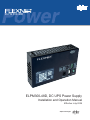
ELPM 300-48D
ELPM300-48D, DC UPS Power Supply
Installation and Operation Manual
Effective: July 2009
Alpha Technologies
®
Power
Alpha Technologies
®
FlexNet ELPM 300-48D
Installation and Operation Manual
010-322-C0-003, Rev C.
Effective Date: July 2009
Copyright© 2009
Alpha Technologies, Inc.
A Member of the Alpha Group
NOTE:
Photographs contained in this manual are for illustrative purposes only. These photographs may not match
your installation.
NOTE:
Operator is cautioned to review the drawings and illustrations contained in this manual before proceeding. If
there are questions regarding the safe operation of this powering system, please contact Alpha Technologies
or your nearest Alpha representative.
NOTE:
Alpha shall not be held liable for any damage or injury involving its enclosures, power supplies, generators,
batteries, or other hardware if used or operated in any manner or subject to any condition not consistent with
its intended purpose, or is installed or operated in an unapproved manner, or improperly maintained.
Contacting Alpha Technologies: www.alpha.com
OR
For general product information and customer service (7 AM to 5 PM, Pacific Time), call
1-800-863-3930
For complete technical support, call
1-800-863-3364
7 AM to 5 PM, Pacific Time or 24/7 emergency support
010-322-C0-003, Rev C
3
Table of Contents
Safety Information.................................................................................................................. 5
1.0
2.0
Installation................................................................................................................. 10
1.1
Introduction..................................................................................................... 10
1.2
FlexNet Installation .........................................................................................11
1.3
Battery and RTS Probe Installation .............................................................. 12
1.4
Output Connections ....................................................................................... 13
1.5
Status Monitoring Connections....................................................................... 13
1.6
Status LEDs ................................................................................................... 15
1.7
AC Input Power Connection........................................................................... 15
1.8
Battery Connection......................................................................................... 15
1.9
Output Distribution Board (optional)............................................................... 16
Specifications............................................................................................................ 17
2.1
ELPM300-48D DC Power Supply................................................................... 17
2.2
Output Distribution Board............................................................................... 19
2.3
FlexNet Installation Kit and Options................................................................ 20
List of Figures
Fig. 1-1 Top view, Mounting Bracket Extension Range..............................................11
Fig. 1-2 Front view, ELPM 300-48D...........................................................................11
Fig. 1-3 Battery Layout, RTS placement.................................................................... 12
4
010-322-C0-003, Rev C
Safety Information
Review the drawings and illustrations contained in this manual before proceeding. If there are any
questions regarding the safe installation or operation of the system, contact Alpha Technologies or the
nearest Alpha representative. Save this document for future reference.
To reduce the risk of injury or death and to ensure the continued safe operation of this product, the
following symbols have been placed throughout this manual. Where these symbols appear, use extra
care and attention.
ATTENTION:
ATTENTION! is used for specific regulatory/code requirements that may affect the placement of equipment
and /or installation procedures.
NOTE:
NOTE gives readers additional information to help them complete a specific task or procedure.
CAUTION!
CAUTION! presents safety information to PREVENT DAMAGE TO customers’
equipment.
WARNING!
A WARNING presents safety information to PREVENT INJURY OR DEATH to the
technician or user.
010-322-C0-003, Rev C
5
General Safety Precautions
To avoid injury:
• This enclosure and its associated hardware must be serviced only by authorized personnel.
• Enclosure must remain locked at all times, except when authorized service personnel are present.
• Remove all conductive jewelry or personal equipment prior to servicing equipment, parts, connectors, wiring, or batteries.
• Read and follow all installation, equipment grounding, usage, and service instructions included in this manual.
• Use proper lifting techniques whenever handling enclosure, equipment, parts, or batteries.
• Batteries contain dangerous voltages, currents and corrosive material. Battery installation, maintenance, service and replacement must be performed by authorized personnel only.
• Never use uninsulated tools or other conductive materials when installing, maintaining, servicing or replacing batteries.
• Use special caution when connecting or adjusting battery cabling. An improperly connected battery cable or an unconnected battery cable can result in arcing, a fire, or possible explosion.
• A battery that shows signs of cracking, leaking or swelling must be replaced immediately by authorized personnel using a battery of identical type and rating.
• Avoid any contact with gelled or liquid emissions from a valve-regulated lead-acid (VRLA) battery. Emissions contain dilute sulfuric acid which is harmful to the skin and eyes. Emissions are electrolytic, which are electrically conductive and are corrosive. Follow the Chemical Hazards notes if contact occurs.
• Do not smoke or introduce sparks in the vicinity of a battery.
• Under certain overcharging conditions, lead-acid batteries can vent a mixture of hydrogen gas that is explosive. Proper venting of the enclosure is required.
• Follow the battery manufacturer’s approved transportation and storage instructions.
CAUTION!
Enclosure, equipment or parts may be damaged or cause damage if used or installed improperly.
To avoid damage:
• Prior to installation, verify that the AC input voltage to the enclosure and its equipment match with respect to voltage and frequency.
• Prior to installation, verify that the output voltage from the enclosure or its equipment match the voltage requirements of the connected equipment (load).
• Prior to installation, verify that the enclosure’s utility service panel is equipped with a properly rated circuit breaker for use with the equipment inside. Refer to manufacturer’s recommendations.
• Review and upgrade utility service panel circuit breaker requirements whenever the equipment within the enclosure is changed.
• Prior to installation, contact local utilities, local building maintenance departments, and cable/ piping locator services to ensure that installation does not interfere with existing utility or building cables/piping.
• Do not exceed the output rating of equipment. Verify load requirements prior and during connection process.
• Prior to handling the batteries, touch a grounded metal object to dissipate any static charge that may have developed in your body.
6
010-322-C0-003, Rev C
Battery Safety
WARNING!
Lead-acid batteries contain dangerous voltages, currents and corrosive material. Battery
installation, maintenance, service and replacement must be performed only by authorized
personnel. Chemical Hazards
Any gelled or liquid emissions from a valve-regulated lead-acid (VRLA) battery contain dilute sulfuric
acid, which is harmful to the skin and eyes. Emissions are electrolytic, and are electrically conductive and
corrosive.
To avoid injury:
• Servicing and connection of batteries shall be performed by, or under the direct supervision of, personnel knowledgeable of batteries and the required safety precautions.
• Always wear eye protection, rubber gloves, and a protective vest when working near batteries. Remove all metallic objects from hands and neck.
• Batteries produce explosive gases. Keep all open flames and sparks away from batteries.
• Use tools with insulated handles, do not rest any tools on top of batteries.
• Batteries contain or emit chemicals known to the State of California to cause cancer and birth defects
or other reproductive harm. Battery post terminals and related accessories contain lead and lead
compounds. Wash hands after handling (California Proposition 65).
• Wear protective clothing (insulated gloves, eye protection, etc.) whenever installing, maintaining, servicing, or replacing batteries.
• If any battery emission contacts the skin, wash immediately and thoroughly with water. Follow your
company’s approved chemical exposure procedures.
• Neutralize any spilled battery emission with the special solution contained in an approved spill kit or with
a solution of one pound Bicarbonate of soda to one gallon of water. Report chemical spill using your
company’s spill reporting structure and seek medical attention if necessary.
• Always replace batteries with those of an identical type and rating. Never install old or untested batteries.
• Do not charge batteries in a sealed container. Each individual battery should have at least 0.5 inches of space between it and all surrounding surfaces to allow for convection cooling.
• All battery compartments must have adequate ventilation to prevent an accumulation of potentially dangerous gas.
• Prior to handling the batteries, touch a grounded metal object to dissipate any static charge that may have
developed on your body.
• Never use uninsulated tools or other conductive materials when installing, maintaining, servicing or replacing batteries.
• Use special caution when connecting or adjusting battery cabling. An improperly connected battery cable or an unconnected battery cable can make contact with an unintended surface that can result in arcing, fire, or possible explosion.
• A battery showing signs of cracking, leaking, or swelling should be replaced immediately by Authorized Personnel using a battery of identical type and rating.
010-322-C0-003, Rev C
7
Battery Maintenance Guidelines
The battery maintenance instructions listed below are for reference only. Battery manufacturer’s instructions
for transportation, installation, storage or maintenance take precedence over these instructions. •
•
•
•
•
•
•
•
To prevent damage, inspect batteries every 3 months for:
Signs of battery cracking, leaking or swelling. The battery should be replaced immediately by authorized personnel using a battery of the identical type and rating.
Signs of battery cable damage. Battery cable should be replaced immediately by Authorized Personnel using replacement parts specified by vendor.
Loose battery connection hardware. Refer to battery manufacturer’s documentation for the correct
torque and connection hardware for the application.
Apply battery manufacturer’s specified antioxidant compound on all exposed connections.
Verify battery terminals and/or exposed connection hardware is not within 2 inches of a conductive
surface. Reposition batteries as necessary to maintain adequate clearance.
Clean up any electrolyte (battery emission) in accordance with all federal, state, and local regulations or codes.
Proper venting of the enclosure is recommended. Follow the Battery Manufacturer’s approved transportation and storage instructions.
Always replace batteries with those of an identical type and rating. Never install old or untested batteries.
Do not charge batteries in a sealed container. Each individual battery should have at least 0.5 inches of space between it and all surrounding surfaces to allow for convection cooling.
All battery compartments must have adequate ventilation to prevent an accumulation of potentially dangerous gas.
Recycling and Disposal Instructions
Spent or damaged batteries are considered environmentally unsafe. Always recycle used batteries or dispose
of the batteries in accordance with all federal, state and local regulations.
Electrical Safety
•
•
•
•
•
•
Lethal voltages are present within the power supply and electrical boxes. Never assume that an electrical connection or conductor is not energized. Check the circuit with a volt meter with respect to the grounded portion of the enclosure (both AC and DC) prior to any installation or removal procedure.
Always use the buddy system when working under hazardous conditions.
A licensed electrician is required to install permanently wired equipment.
Input voltages can range up to 240 VAC. Ensure that utility power is disabled before beginning installation or removal.
Ensure no liquids or wet clothes contact internal components.
Hazardous electrically live parts inside this unit are energized from batteries even when the AC input
power is disconnected.
Mechanical Safety
8
•
•
Keep hands and tools clear of fans. Fans are thermostatically controlled and will turn on automatically.
Power supplies can reach extreme temperatures under load.
•
Use caution around sheet metal components and sharp edges.
010-322-C0-003, Rev C
Grounding Connection
In order to provide a ready, reliable source of backup power it is necessary to establish a grounding system
that not only provides for the safety of the service personnel responsible for its operation and maintenance,
but also facilitates the proper operation and protection of the equipment within the network. Such a grounding
system will provide protection with respect to operator safety, system communication, and equipment
protection.
Safety Ground
The safety ground is a two-part system. The first part is a return path for stray current back to the input
breaker, and the second is a return path from the Alpha enclosure to a second ground rod.
Typically, the safety, or utility ground, provides a return path to the input breaker or fuse panel by means of a
connection to an appropriate driven ground rod at the base of the power pole. This path must meet National
Electric Code (NEC) as well as local codes to ensure the breaker will open, preventing unwanted current flow
from posing a hazard to service personnel.
The second part of the safety ground arrangement is the ground path between the Alpha enclosure and a
second ground rod located at least 6 feet away from the driven ground rod at the power pole. The second
ground rod and enclosure are connected via an AWG #6 solid copper wire buried at a depth of 8-12 inches.
The wire is connected to the cabinet by means of a ground lug on the back of the cabinet (for pole-mounted
enclosures), or to a ground lug inside the cabinet (for ground-mounted enclosures), and connected to the
ground rod by means of a listed grounding clamp suitable for direct burial, or exothermic weld. Normally it is
specified that the impedance of this ground can be no greater than 25 ohms at 60 Hertz. If, however, dual
ground rods are installed approximately eight feet apart, it is not necessary to measure the impedance of the
ground rods to meet the maximum 25 ohms specification—it is assumed that the impedance specification is
met.
Strike (Lightning) Ground
Lightning strikes, grid switching, or other aberrations on the power line all have the potential to cause “fast
rise-time currents” which can cause damage to the powering system. Without a low-impedance path to
ground, the current, while traveling through wires of varying impedance, can produce high voltages which will
damage the powering equipment. The most viable method available to protect the system from damage is to
divert these unwanted “fast rise-time currents” along a low-impedance path to ground. A low-impedance path
to ground will prevent these currents from reaching high voltage levels and posing a threat to equipment. The
single-point grounding system provides a low-impedance path to ground, and the key to its success is the
proper bonding of the ground rods, so the components of the grounding system appear as a single point of
uniform impedance.
WARNING!
Low impedance grounding is mandatory for personnel safety and critical for the proper
operation of the cable system.
010-322-C0-003, Rev C
9
1.0 Installation
1.1 Introduction
The FlexNet Fiber UPS model ELPM300-48D is a small-form, outdoor-rated, uninterruptible
power supply for distributed communications networks. The unit can be installed in a variety
of Alpha enclosures and is powered by 120Vac or 240Vac line input or 48Vdc battery
string. The 48Vdc, 300 Watt output provides uninterruptible power for various distributed
communications networks.
Features and benefits:
Power Modules can be used in a variety of Alpha enclosures
Rugged 48Vdc UPS for outdoor or indoor applications
Temperature compensated battery charging for extended battery life
Visual and electrical indicators for on-site and remote reporting
Flexible cabinet mounting options
Included with the unit are:
Mounting Brackets; see
Section 1.2.
RTS (the Remote
Temperature Sensor gets
its backup power from a
48VDC battery string);
See Section 1.3.
Output Cable Kit; see
Section 1.4
Alarm Telemetry Connector;
Status Monitoring, see
Section 1.5.
Options include a Battery
Heater Mat, Output
Distribution Board and
Battery Cable Kit.
10
010-322-C0-003, Rev C
1.0
Installation, continued
1.2 FlexNet Installation
Use #6 screws and attach mounting brackets to side of unit. Use #10 screws (at least one per
side and attach unit on the mounting bar in the upper compartment of the enclosure.
3.40”
2.50” (86.36mm)
(63.5mm)
3.30”
(83.82mm)
4.00”
(101.6mm)
Fig. 1-1, Mounting Bracket Extension Range
(Top view)
11.06” (281mm)
2.18”
(55.3mm)
5.5”
(139.7mm)
4.375”
(111mm)
5.98”
(152mm)
10.10” (257mm)
12.00” (304.8mm)
Fig. 1-2, Reference dimensions, ELPM 300-48D
(Front view)
010-322-C0-003, Rev C
11
1.0
Installation, continued
1.3 Battery and Remote Temperature Sensor Probe Installation
The diagram below is for illustrative purposes only. Exact battery orientation may vary. Do
not connect the batteries to the Flexnet 300 unit at this time. The RTS must be taped to the
side of a center battery as shown below. Connect the other end to the RJ-11 temperature jack
on the front of the power supply.
Air Gap
Red
Black
4A
3A
To “Battery” connector
2A
Red
1A
To “Temperature” connector
Fig. 1-3, Battery Layout and RTS Placement
12
010-322-C0-003, Rev C
1.0
Installation, continued
1.4 Output Connector
The output connection is located on the front panel of the unit. Plug the 48VDC fiber node
into this connector.
1.5 Status Monitoring Connector
The Status Monitoring connector is located on the front panel of the unit. Associating with
this connector, an opto-coupler transistor array is connected between the output alarm pins
(Batt Low, Batt Miss, Repl Batt and AC Fail) and the ground pin (Tel Comm) as shown. In
the normal state, all the transistors are turned off and all the alarm pins are separated to
the ground. When an alarm is present, the micro controller will turn on the corresponding
transistor to short the alarm pin to the ground.
010-322-C0-003, Rev C
13
In order to correctly receive the alarm signals, it is recommended to put a pull-up resistor
between the receive circuit’s logic power (3.3V or 5V) and each alarm line at the alarm
signal monitor side, as shown below. The resistance may vary per current requirement of the
receive circuit.
All four alarm lines are LOW at the normal operation. When an alarm is present, the
corresponding line will be HIGH. For example: when AC is turned off, the monitor will see a
HIGH presence at AC fail line while the remaining three alarm lines—Repl Batt, Batt Low and
Miss Batt—remain LOW.
Time Delay in Reporting Alarm
Customers may see a time delay between failure and alarm reports. An alarm signal is
reported only after a failure persists for a certain period of time. This time delay is designed
to avoid customers being annoyed by trivial short period failures (for example: short time AC
failure).
Time Delay for Each Alarm
AC fail — The unit reports AC fail after the battery voltage is less than 52.8V and the battery
discharges for 17 Amp-mins.
Batt Low — The unit reports Batt Low after the battery voltage is less than 44V for 30
seconds.
Batt Miss — The unit reports Batt Miss after the battery is disconnected for 30 seconds. It
may report Batt Low at the same time.
Repl Batt — the unit reports Repl Batt after it diagnoses the battery as bad. However, the
unit runs a battery diagnosis once a month; it might take awhile for the system to diagnose
battery failure if the failed battery does not also have other problems (such as low battery
voltage).
14
010-322-C0-003, Rev C
1.0
Installation, continued
1.6 Status LEDs
The status LEDs are located on the front panel
of the unit. Normal operation is indicated by
the green LED ON, and the red LED OFF. LED
status indication also has a time delay when
reporting failures. The time delay is similar to
that illustrated in Section 1.5.
1.7 AC Input Power Connection
The Flexnet 300 offers switchable
AC input power capability. Slide
the input power switch (located
on the side of the housing) to the
correct voltage and plug the AC
power cord into the receptacle.
Verify that the green LED is
continuously illuminated and the
red LED begins to blink within
20 seconds, indicating that the
battery pack is not yet installed.
1.8 Battery Connection
Using a multimeter, verify that 48Vdc is present at the connection
leading from the battery pack, and the polarity is correct. Connect the
battery pack to the Battery connection on the front of the unit. Note the
shape of the Battery connectors which prevent incorrect hookup. Verify
that the red alarm LED goes out within 10 seconds.
010-322-C0-003, Rev C
_
+
15
1.0
Installation, continued
1.9 Output Distribution Board (optional)
The Output Distribution Board (Alpha P/N 745-577-20) splits the ELPM300-48D’s 300W
output into two 150W isolated outputs. Each output has its independent protection circuit.
One output overload or short circuit will only trigger its own protection and not affect the other
circuit’s normal operation.
The ODB measures 6.25” W x 3.875” H x 2” D (159mm W x 98.4mm H x 51mm D).
J3 — 150W Output
Output wire harness
(Alpha P/N 875-262-20)
J1 — Input connector
300 W output from unit
Input wire harness
(Alpha P/N 875-255-20)
J2 — 150W Output
Output wire harness
(Alpha P/N 875-262-20)
NOTE:
The Output Distribution board is supplied with one interconnection cable (Alpha P/N 875-255-20), and
one output wire harness (Alpha P/N 875-262-20). The existing output wire harness is replaced by the
interconnection cable, and is transferred to one of the output connectors.
The adapter bracket mounts to the cross bar in
the enclosure, which mounts next to the power
supply.Attach the Output Distribution Board to
the Adapter Bracket by aligning and sliding the
hanger brackets onto the bracket screws.
1. Loosen both screws enough to allow the
bracket prongs to slide over the screw
heads.
2. Firmly tighten only the bottom screw to
secure the module.
16
3.75”
95.25mm
010-322-C0-003, Rev C
2.0 Specifications
2.1 ELPM300-48D DC Power Supply
Mechanical
Housing
Sheet metal enclosure
Mounting
Wall mounting brackets included
Rack-mounting via optional 19-inch EIA brackets
Material
Finish
Cooling
Aluminum
Painted black
Natural convection
Acoustic Noise, Line Mode
50dBa at 1m (maximum)
Acoustic Noise, Batt Mode
50dBa at 1m (maximum)
Electrical — AC Input
Voltage, Minimum
85/170 factory setting
Voltage, Maximum
132/264 selectable via slide switch
Frequency
Frequency Tolerance
50/60Hz
± 10%
Source Impedance
<5% FL equivalent impedance
Input Current Limit
7A
Minimum Power Factor
60%
Harmonic Input Current
Class A per CE 1000-2-3 (230Vac 50Hz)
Maximum Surge Current
50A peak
Protection
Line Leakage
Surge/Transient protection
Power Cord
Fuse, MOV
2.5mA max at 264Vac 50Hz
IEEE Std C62.41-1991 level C
3’ NEMA 515 120VAC plug
Electrical Output — 48Vdc
Power Capability
Voltage
Number of Outputs
Startup Overshoot Range
Frequency
Transient Reasponse
Ripple Voltage, Maximum
Maximum Efficiency
Output Grounding
Short Circuit Protection
320W, continuous
40 to 62Vdc (For some models, max output voltage is 56Vdc*)
1
120% of nominal, 0.5 sec. max.
DC
Not to exceed 1s
500mV RMS
85% within normal operating range
Floating, SELV
Electronic
Overload Protection
Integral
Active Load Sharing
None
*Models 010-322-22-XXX and 010-322-23-XXX
010-322-C0-003, Rev C
17
2.0
Specifications, continued
2.1
ELPM300-48D DC Power Supply, continued
Electrical — Battery Bus
Voltage
Recharge Time
Temperature Compensation Range
Temp. Compensation dV/dC
End of Discharge Voltage
48Vdc nominal
10X Discharge Rate to 90% state of charge
-20°C to +40°C
-72mV/°C per string
42Vdc (1.75V/cell)
Discharge Current
6A
Charge Current
6A
Quiescent Current
<5mA after end of discharge (EOD)
Battery Grounding
Float, SELV
Electrical — Local Display
LED
STATUS
Green Steady
Output OK
Green Blinking
Standby Operation
Both Blinking
Fault
Red Blinking
Batt Low/Missing
Red Steady
Replace Battery
Electrical — Status Monitor Interface
Status Monitoring Alarms
Battery Low
Battery Missing
Replace Battery
AC Fail
Environment
Operation Temperature
-40°C to 55°C (-40°F to 131°F)
Storage Temperature
-40°C to 70°C (-40°F to 158°F)
Solar Loading
Inclusive maximum temperature operation
Humidity
0-95%, non-condensing
Altitude
Temp. spec applicable to 5,000ft (1524m). Above 5,000ft,
de-ratemax temp 2°C per additional 1,000ft (304.8m)
Physical
Dimensions
Weight
18
10.10” W x 5.98” H x 3.30” D (257mm W x 152mm H x 84mm D)
4.4lb/2.0kg
010-322-C0-003, Rev C
2.0
Specifications, continued
2.2 Output Distribution Board (optional)
Electrical — General
Efficiency
> 90%
Grounding
Positive or negative terminal (user preference)
Startup Time
< 20s
Electrical — Input
Voltage, minimum
42Vdc
Voltage, nominal
48Vdc
Voltage, maximum
62Vdc
Electrical — Output I/II
Voltage, minimum
41 Vdc
Voltage, maximum
61Vdc
Current, nominal
Output Ripple, max.
3A
500mV RMS
Overcurrent/Short Circuit Protecting
Mode
Hiccup
Protection Trigger
<10ms
Threshold
4A
Environment
Operating Temperature
-40°C to +65°C (-40°F to +149°F)
Storage Temperature
-50°C to +70°C (-58°F to +158°F)
Solar Loading
Inclusive maximum operating temperature
Humidity
0-95%, Non-condensing
Altitude
Temp. spec applicable to 5,000ft (1524m). Above 5,000ft,
de-ratemax temp 2°C per additional 1,000ft (304.8m)
010-322-C0-003, Rev C
19
2.3 FlexNet Installation Kit and Options
The following items are part of the FlexNet installation package and options for the
ELPM300-48D power supply.
NOTE:
The optional 10” x 17” Battery Heater Mat (Alpha P/N 189-057-10) is not shown .
Battery Cable Kit (Alpha P/N 875-218-21)
See Section 1.8
Output Cable Kit (Alpha P/N 875-262-20)
See Section 1.4
Mounting Brackets/Hardware
(Alpha P/N 604-564-C4)
See Section 1.2
(RTS) Remote Temperature Sensor
(Alpha P/N 740-162-27)
See Section 1.3
Alarm Telemetry Connector
(Alpha P/N 545-866-10)
19” EIA Rack Mounting Brackets
(Alpha P/N 604-907-A1)
20
010-322-C0-003, Rev C
Power
Alpha Technologies
®
Alpha Technologies
3767 Alpha Way
Bellingham, WA 98226
USA
Tel: +1(360) 647-2360
Fax: +1(360) 671-4936
Web: www.alpha.com
Alpha Technologies Ltd.
4084 McConnell Court
Burnaby, BC, V5A 3N7
CANADA
Tel: +1(604) 430-1476
Fax: +1(604) 430-8908
Alpha Technologies
Europe Ltd.
Twyford House
Thorley
Bishop's Stortford
Herfordshire
CM22 7PA
UNITED KINGDOM
Tel: +44 1279-501110
Fax: +44 1279-659870
Alpha Technologies GmbH
Hansastrasse 8
D-91126 Schwabach
GERMANY
Tel: +49-9122-79889-0
Fax: +49-9122-79889-21
Alphatec, Ltd
P.O. Box 56468
Limassol, Cyprus
CYPRUS
Tel: +357-25-375675
Fax: +357-25-359595
Alpha Technologies France
34, Grande Rue
Bétheny, F-51450
France
Phone: +33 32 64990 54
Fax: +33 95 60205 01
Due to continuing product improvements, Alpha reserves the right to change specifications without notice.
Copyright © 2009 Alpha Technologies, Inc. All rights reserved. Alpha is a registered trademark of Alpha Technologies. 010-322-C0-003 Rev. C