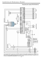
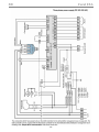
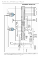
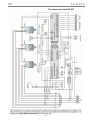
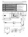
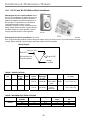
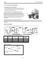
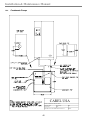
1
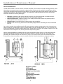
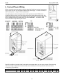
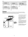
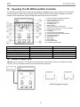
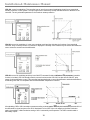
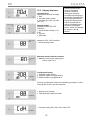
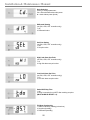
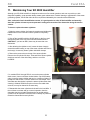
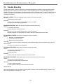
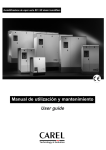
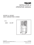
SD Electronic Steam Humidifiers Installation & Maintenance Manual Read and Save these Instructions Installation & Maintenance Manual How The SD 2000 Works The SD 2000 humidifier is what is called an “electrode” humidifier. This means that instead of heating elements, metal electrodes are immersed in water contained in a plastic cylinder. When steam is required for humidification, electric current flows through the water between the electrodes. The minerals in the water provide both the conductance and resistance for electric flow, thus producing steam. This technology is VERY advanced over electric element type humidifiers and has the following advantages: • • • • Efficiency: Operates at 94% energy efficiency over 95% of the life of the cylinder as compared to 90% reducing linearly to less than 60% over the life of an element type humidifier. Reduced maintenance: Instead of scraping out a metal pan and electric element, the plastic cylinder is simply replaced with a completely fresh one. Response time: is sometimes twice as fast as element type humidifiers. Failsafe: If the unit runs dry, power flow is automatically stopped where in element type units, the elements burn out. On a call for humidity, the humidifier controller (R) closes the power contactor, putting power to the electrodes in the steam cylinder (B), and opens the fill valve (C) to allow water to flow into the water fill tank (V). In, or in line with, this tank is a conductimeter (D) which reads the water quality. As the water level rises in the cylinder, it begins to cover the electrodes and current begins to flow, warming the water and producing steam. When the desired amperage is reached (which is directly proportional to steam output), or if the water reaches the high level electrodes (E), the water fill will stop. As water is boiled off, minerals will build up in the cylinder and periodically the controller will open the drain valve or pump (S or P) and remove some of the mineral laden water. Eventually the cylinder electrodes are used up and the electronic controller signals time to change the cylinder. B. Steam cylinder C. Fill valve D. Conductimeter E. High level electrodes P. Drain pump R. Electronic controller S. Drain valve T. Overflow pipe V. Water fill tank 2 SD Carel USA Table of Contents 1. 2. General Installation Rules......................................................................................................................... 5 Mount Steam Humidifier .......................................................................................................................... 6 2.1. Position of Steam Outlets.................................................................................................................. 7 2.2. Mounting The Humidifier................................................................................................................. 7 3. Connect Plumbing..................................................................................................................................... 8 3.1. Connect Water Feed.......................................................................................................................... 8 3.2. Connect Water Drain ........................................................................................................................ 8 4. Connect Power Wiring.............................................................................................................................. 9 5. Connect Control Wiring.......................................................................................................................... 10 5.1. Controls Placement ......................................................................................................................... 10 5.2. Controls Wiring .............................................................................................................................. 10 6. Install Steam Distributor Pipes ............................................................................................................... 12 7. Install Steam Hoses................................................................................................................................. 13 8. Install Room Distribution Unit ............................................................................................................... 14 9. Start up and Check out of the SD 2000 Humidifier................................................................................ 16 10. Operating The SD 2000 Humidifier Controller .................................................................................. 17 10.1. Available Controller Types......................................................................................................... 17 10.2. Display Sequence........................................................................................................................ 19 11. Maintaining Your SD 2000 Humidifier.............................................................................................. 21 11.1. Optimizing Cylinder Life on the SD 2000 Electrode Steam Humidifier.................................... 23 12. Trouble Shooting ................................................................................................................................ 24 13. Replacement Parts............................................................................................................................... 30 14. Technical Specifications ..................................................................................................................... 38 14.1. ASWH / ASDH – ASDH / ASDC Wall – Duct Temperature/Humidity Sensors ...................... 39 14.2. HC-101 and HC-201 Wall and Duct Humidistats ...................................................................... 40 14.3. PC-301 Air Proving Switch ........................................................................................................ 41 WARNING: Your humidifier requires water to operate. Do NOT mount it above materials or machinery that could be damaged if a leak occurs. Carel assumes no responsibility for consequential or inconsequential damage as a result of any leaks. 3 Installation & Maintenance Manual Your SD 2000 steam humidifier will consist of: Steam humidifier unit Steam distributor pipe(s) or Room Distribution Unit (blower) Steam hose & condensate hose, hose clamps Mounting bracket, mounting hardware and water fill quick connect fitting Humidity sensors or controllers IMPORTANT: BEFORE beginning installation: Check for shipping damage to cartons. Mark the shipping waybill accordingly. Open cartons and check for any hidden damage. Mark the shipping waybill accordingly. Check packing slip to insure all items have been received. Notify Carel immediately of any shortages or damaged parts. You must notify Carel within 5 working days of any shortages. 4 SD Carel USA 1. General Installation Rules Mount the humidifier unit as close to the steam distributor pipe or Remote Distribution Unit as possible to minimize condensate. Mount the humidifier unit below the steam distributor pipe or RDU whenever possible. Insure that a slope can be maintained in the steam hoses. Avoid kinks and gullys in steam hoses which can trap condensate and cause problems. Certain mounting clearances must be maintained to allow access for maintenance, and for steam discharge from an RDU: DIMENSION A B C D E F 101-103, 303-305 72” 12” 12” 12” 24” 12” 106, 308-313 72” 24” 24” 24” 24” 12” 323-3B3 120” 36” 36” 36” 48” 12” NOTE: Dimension A is clearance required in front for maintenance and RDU steam discharge. NOTE: Maximum length of rubber steam hose is 20 feet. Insulated copper tubing to 40 feet. 5 Installation & Maintenance Manual 2. Mount Steam Humidifier Sizes and Weights FACTOR C – HEIGHT A – WIDTH B – DEPTH DRY WEIGHTS – LBS. WET WEIGHTS – LBS. 101 UNIT MODEL NUMBER: DIMENSIONS AND WEIGHTS 102 103 106 303 305 308 313 323 333 342 360 384 22.5” 25.2” 22.5” 25.2” 34” 34” 13” 14.2” 13” 14.2” 24.5” 40.25” 7.5” 8.25” 7.5” 8.25” 14” 14” 45 50 45 50 132 209 53 66 53 66 172 289 6 3B3 34” 56” 14” 280 400 SD Carel USA 2.1. Position of Steam Outlets UNIT MODEL NUMBER: DIMENSIONS DIMENSION 101 102 103 106 303 305 308 313 323 333 342 360 384 3B3 A 3.2” 3.2” 3.2” B 3.2” 4.1” 3.2” 4.1” 6.7” 6.7” 6.7” C 12.2” 12.2” D 3.7” 4.3” 3.7” 4.3” 5.7” 5.7” 5.7” NOTE: Allow clearance on the top of the humidifier for the steam hoses to exit and travel to their duct distributor pipes (if used). 2.2. Mounting The Humidifier Mount the supplied humidifier mounting bracket to the wall using screws or lag shields capable of supporting the weight. The top of the bracket will create a gap to the wall. Hang the unit on the bracket and secure the bottom using screws or lag shields (1, 2, or 3). Generally, the steam cylinder must be removed to complete this step. DIMENSION A B C 101 102 2.0” 4.3” 8.3” 103 106 2.0” 4.3” 8.3” UNIT MODEL NUMBER: DIMENSIONS 303 305 308 313 323 333 342 2.0” 2.0” 2.6” 4.3” 4.3” 5.9” 8.3” 8.3” 15.9” 7 360 384 4.1” 5.9” 31.9” 3B3 2.8” 5.9” 46.9” Installation & Maintenance Manual 3. Connect Plumbing 3.1. Connect Water Feed The water feed connection is a 3/4” MPS male connection on the bottom of the humidifier (2 on SD360 & 384 models, 3 on SD3B3). Carel supplies a plastic adapter that screws onto the fill fitting and gives a 1/4” OD compression fitting for plastic or copper tubing. Since there is a strainer built into the bottom of the fill valve fitting, you should use only the plastic adapter supplied as it is easily removable for maintenance. To insure proper filling of the unit during operation, run a 1/2” water line to within 3 feet before reducing to 1/4” OD for the final connection. A 1 1/2” air gap is built into the unit to pass all UL and local codes regarding backflow prevention. WARNING: The plastic fill fitting should be hand tightened only. A wrench may be used on the 1/4” OD compression fitting. NOTE: Use only potable water. Water conductivity should be between 125 and 1250 micromhos. If water conductivity is over 250 micromhos, do not use softened water. Demineralized water cannot be used as there are no minerals to conduct the electricity. 3.2. Connect Water Drain The drain connection on the SD101 through 313 units is a 3/4” FPS female threaded fitting. Connect a standard 3/4” MPT CPVC fitting to this connection. Use a generous amount of thread sealant. DO NOT overtighten and DO NOT use metal fittings as they can crack the plastic drain pan. Drain lines from steam humidifiers MUST be trapped immediately below the unit (Shown in figure to the right) in order to prevent flash steam from rising out of the drain pipe and condensing inside the humidifier unit. On units SD323 and up, the drain connection is a 1 1/2” O.D. plastic pipe. Insert the plastic drain elbow into a 1 1/2” CPVC drain line with a 2” bell adapter. Do not glue to humidifier drain. WARNING: Drain water can be up to 200°F. 8 SD Carel USA 4. Connect Power Wiring Before connecting any power supply, check the data label inside the electrical compartment door to make sure the unit configuration matches the power supply. If it does not match, do NOT connect power – call your Carel representative. Insert the high power wires through the strain reliefs provided on the BOTTOM of the humidifier and wire directly to the field wiring terminals as shown below without loops. DO NOT bring high power wires into the humidifier from any other point. High power wires near the low voltage controls can damage them and VOID WARRANTY. An external, fused disconnect should be provided by the installer. Each SD humidifier is internally wired for the maximum amperage that it can see on any voltage. Electrical wiring sizes must match all national and local electrical codes. Generally, the following maximum wire sizes can be connected to SD humidifiers: SD MODELS Max. Wire Size – Ga. 101 14 102 14 103 12 106 10 303 14 305 12 9 308 10 313 8 323 4 333 6 342 2 360 1 384 1/0 3B3 4/0 Installation & Maintenance Manual 5. Connect Control Wiring 5.1. Controls Placement A typical humidifier control system includes a wall or return duct sensor or controller, a high limit duct humidistat, and an air proving switch. Placement of these devices is critical to proper operation of the overall system. The return air RH sensor must always be located BEFORE any outside air intake, in order to insure accurate sensing of the air from the space. Alternatively, a room RH sensor or humidistat can be used. Room sensors should be located on an inside wall or post and should not be hit by any discharge air streams from ducts. In a 100% outside air system, the RH sensor may be placed in the supply duct, at least 10 feet down stream of the distributor pipe to act as both hi-limit and control. The airflow switch must be positioned to accurately open on a loss of air flow, to prevent the humidifier from running when there is no air to absorb the moisture. The hi-limit humidistat must be positioned far enough down stream of the steam distributor pipe(s) to prevent it from getting wet, but still allow it to accurately prevent overhumidification of the duct that could result in condensation. 5.2. Controls Wiring The SD humidifier controllers are preprogrammed from the factory to operate either as On/Off (CDC), Proportional from a control signal (CDP), or Proportional from a sensor input (CDH, CDD). Wiring the CDC On/Off Controller: The CDC controller is for On/Off control in response to an external closed contact as from a humidistat or DDC relay. DO NOT apply voltage to any input on a CDC controller. 10 SD Carel USA Wiring the CDP Proportional Controller The CDP controller is designed to accept various modulating input signals: 0-10 Vdc, 0-20 Vdc, 2-10 Vdc, 0-20 mAdc and 4-20 mAdc. The DIP switches located on the back of the controller must be set for the appropriate input signal. NOTE: the modulating signal must come from a controller or DDC system, not a sensor. The CDP controller follows the input signal being off at low signal and full on at full signal. Wiring the CDH Humidity Readout Proportional Controller The CDH controller is designed to accept an input signal from a humidity sensor (not controller). This input signal is then displayed on the controller as the relative humidity. Set point and differential are entered into the CDH controller making it stand-alone. Wiring the CDD Humidity Readout Proportional Controller/Dehumidify The CDD controller is designed to accept an input signal from a humidity sensor (not controller). This input signal is then displayed on the controller as the relative humidity. Set point and differential are entered into the CDD controller making it stand-alone. The connections 66-67 are only for connection to the Macrobase controller for humidification/dehumidification management of air handling units. Max: 5ma, 30vdc. There is also a dehumidify contact that can be connected to a dehumidifier. The dehumidify contact is limited to 24 Vac/dc at 1 Amp. There is also a CDT controller that reads a temperature sensor input and controls the SD humidifier for use in a Turkish bath. It is wired the same was as the CDH controller, but with a temperature sensor instead. 11 Installation & Maintenance Manual 6. Install Steam Distributor Pipes If your SD 2000 humidifier was supplied with duct steam distributor pipes, they must be mounted completely level in the duct with the steam outlet holes facing up as shown to the right. Support the end of longer distributor pipes if needed. Distributor pipes should be mounted per the diagrams shown below, with a minimum of 6” from the center of the distributor pipe to the top of the duct and 3” minimum to the bottom. Generally the distributor pipes should be mounted in the center of the air stream. Multiple pipes need to be staggered on a diagonal to prevent the steam discharge from the lower pipes from impinging on the upper ones. In vertical ducts, the distributor pipes are mounted in the center with the holes facing up as shown at right. The airflow may be up or down, but when the airflow is down, maximum velocity is 1,500 fpm. To install the distributor pipes: 1. Cut a key shaped hole in the side of the duct to match the steam pipe and condensate return. 2. Apply silicone sealant to the mounting plate and insert the pipe through the hole and secure it with 4 sheet metal screws. 3. Connect the steam and condensate hoses using the hose clamps supplied. IMPORTANT: Allow 3 feet of straight duct downstream of the distributor pipes when the air temperature will be >55oF. Allow 6 feet of straight duct if the air temperature will be <50oF. Always allow 3 feet upstream. 12 SD Carel USA 7. Install Steam Hoses NINETY PERCENT (90%) OF ALL OPERATION PROBLEMS ARE CREATED BY IMPROPER STEAM PIPING FROM THE HUMIDIFIER UNIT TO THE DUCT DISTRIBUTOR PIPES. To avoid these problems, remember one simple fact when running the steam hose: steam naturally flows up hill, and condensate naturally flows down hill. Nothing must impede the free flow of either steam to the distributor pipes or condensate back to the SD unit or the drain. If Copper tubing is used, use two 45° angles or sweeping elbows rather than sharp 90° elbows. Follow one simple rule: Run the steam hose or piping to avoid any kinks, sharp elbows, or low spots that could collect or restrict the flow of steam to the distributor pipe, or the flow of condensate back to the humidifier. Support the hose adequately to avoid sags. The following diagrams are to provide you with some guidelines. If you have a situation you are unsure of, please contact the factory for instructions. IMPORTANT: Maximum length of rubber steam hose is 20 feet. Insulated copper tubing may be up to 40 feet. Hose sizes= 7/8" I.D. for units SD101-103, 303-305, 1 1/4" I.D. for units SD106, 308-3B3. 13 Installation & Maintenance Manual 8. Install Room Distribution Unit Models SD101-313: If your SD 2000 humidifier was supplied with a direct mount RDU (Room Distribution Unit), it will have been shipped in place, ready to go. Simply mount the humidifier unit on the wall per the instructions in Section 2 and proceed to the unit wiring instructions. If the RDU was supplied separately or is a retrofit, mount the RDU to the top of the humidifier as follows: 1. Connect the steam and condensate hoses to the outlets on the bottom of the RDU and secure using the hose clamps supplied. 2. Slip the hoses and connector wires through the holes in the top of the humidifier and line up the 2 corner pins into the 2 keyed slots on the top of the humidifier. Push the RDU toward the back of the humidifier to force the 2 corner pins into the slots. 3. Open the humidifier doors and use the supplied self-tapping screws to secure the RDU to the top of the humidifier. 4. Connect the steam hose to the top of the cylinder outlet and secure it with the supplied hose clamp. Run the condensate hose behind the cylinder on the left side and lay it in the drain pan. Push the 2 wire spade connectors from the RDU, into the socket located at the back of the electrical compartment in the humidifier, labeled X1 and X2 (there is no polarity). NOTE: If RDU wires are extended, use non-insulated spade connectors to plug into X1 and X2. 5. OPTIONAL: If the RDU supplied is for remote mounting, then mount the RDU to the wall on brackets (not supplied) and connect the steam and condensate hoses in the same way. Extend the control wires and plug them into the humidifier unit also in the same way. CAUTION: These wires carry line voltage. Field wiring must conform to NEC and local codes. 14 SD Carel USA Models SD323-3B3: The VRDXL used on the SD323-3B3 units is only available as a remote unit (wall mounting bracket supplied), although it can be mounted on the wall directly over the humidifier unit if desired. (2 VRDXL units are required for models SD360-384 and 3 are required for the SD3B3). Dimensions shown above. 1. Secure the VRDXL to the wall using the wall mounting bracket supplied. 2. Connect steam and condensate hoses to the bottom inlets and run to the top of the humidifier unit. Run wires from X1 and X2 in the VRDXL into the humidifier’s electrical compartment. 3. Connect the steam hoses to the top of the cylinder outlet and secure them with the supplied hose clamp. Run the condensate hose to the unit drain pan and lay it in the bottom so that it will drain into the drain pan. 4. Connect the wires from X1 and X2 in the VRDXL to terminals X1 and X2 in the back of the humidifier unit. 15 Installation & Maintenance Manual 9. Start up and Check out of the SD 2000 Humidifier Startup Checklist: 1. Water and drain lines are connected properly. Drain lines are trapped per Section 3. Fittings are tight. NOTE: Inlet water pressure must be between 15 and 150 psi. If higher than 150 psi, install regulator. 2. All power connections, including internal ones, have been checked to insure they are tight. Power supply matches the unit power data label. 3. Wires to the electrodes on top of the cylinder are tight. 4. Steam and condensate hoses are properly installed, and supported to prevent sags. Hose clamps are tight. 5. Sensors and limits are connected per the instructions. 6. Airflow switch (if used) is wired to close on air flow and open on air loss. 7. Hi-limit duct humidistat is wired to open on humidity rise and is set for 85 to 90%RH. Startup Procedures: 1. Turn on water to the humidifier and check for leaks in the piping. 2. With the humidifier On/Off switch in the OFF position, turn on external power to the humidifier. 3. Set the humidifier On/Off switch to the ON position. 4. CDC controllers: Set the humidistat setpoint above the room humidity. CDP controllers: Set the controller or DDC system to a full call for humidity. CDH/CDD controllers: Press SEL until the cursor points to SET and then enter a setpoint higher than the room humidity. 5. After the HUMIDIFY ON lights up, the FILL will light up 15 seconds later, and the unit will open the fill valve and begin to fill with water. Startup with Water Conductivity Higher than 1000 Micromhos: As the humidifier fills with water, it will reach its required amperage draw (and steam output) before water reaches the top of the cylinder. As the water warms and begins to boil, its conductivity will increase and the humidifier will periodically open the drain valve to reduce the amperage and prevent overamping. Once at a boil, the unit will go into normal drain/fill operation. Startup with Water Conductivity Lower than 1000 Micromhos: In this case, the humidifier will fill completely with water before reaching the required amperage draw. Initially an E05 prealarm will appear possibly followed by an E02 low output prealarm. The humidifier will allow the water to boil off of the cylinder full probes to eliminate the prealarms and will then seek to concentrate the minerals in the cylinder until the unit is able to reach full output. This process may take one or more hours. Startup with Water Conductivity Lower than 100 Micromhos: When the water conductivity is less than 100 micromhos, there is not enough conductance in the water for the humidifier to reach even low capacity. In this case, the E05 and E02 prealarms will appear and may be followed quickly by an E07 or E08 alarm. To “jump start” the humidifier, turn off the power, remove the hose from the top of the cylinder and drop in a teaspoon full of salt (shake cylinder gently to mix) or two Alka-Seltzer® to raise the water conductivity, and restart the unit. Once the water is brought to a boil, the unit will be able to automatically take care of maintaining the proper mineral concentration. If the conductivity is less than 50 micromhos contact the factory for instructions. Anti-Foaming System: If water in the cylinder starts to foam, the unit may deactivate the power contactor and activate the fill valve for a short period. If the foam collapses, the unit will then activate a drain cycle and refill. This can occur repeatedly until the foaming has been eliminated and is a normal routine. 16 SD Carel USA 10. Operating The SD 2000 Humidifier Controller The SD 2000 controllers all have the same general display and keypad as shown below. Initially, the CDC and CDP controllers default to display of the amperage, while the CDH and CDD controllers default to display of the relative humidity. Some indicators are simply for display while others blink and can be modified. 1. 2. 3. 4. 5. 6. 7. 8. 9. 10. 11. 12. 13. 14. 15. 16. 17. Relative humidity or temperature displayed Fill water conductivity displayed Alarm condition active Selected set point value Humidification ON Alarm condition Reset button (press to reset alarms) Selection button (press to move cursor in display) Parameter increase button LCD Display Actual current (Amps) displayed Selected maximum steam output displayed Configuration displayed Selected differential Water filling Water draining Manual drain button 18. Parameter decrease button Parameter Max Production Set Point (%RH) Differential (%RH) High Limit Alarm (%RH) Low Limit Alarm (%RH) Type of Drain Valve 30%-100% of kg steam output 0-100 1-19 0-100 0-100 Cd or Td Default Setting 70% of kg steam output 50 4 80 20 Cd 10.1. Available Controller Types CDC 303: control is ON-OFF. The controller has an external dry contact input coming from any ON-OFF external controller. The only selectable parameter is the maximum steam production. 17 Installation & Maintenance Manual CDP 303: control is modulating. The controller has an input for an external modulating signal from a proportional humidity controller or DDC system. The input signal can be selected by the dip-switches located on the back of the controller. The only selectable parameter is the maximum steam production. CDH 303: control is modulating. It is the most complete model and also includes the functions of a proportional controller. Only a humidity sensor is connected. It displays the humidity value measured by the sensor and allows the user to select the set-point and the differential. CDD 303: control is modulating and there is an ON-OFF command for dehumidification. The proportional controller function is included. CDD 303 actually offers the same functions as the CDH 303, but also has an ON-OFF relay output for dehumidification control. This controller has been designed to control humidification and dehumidification in air handling units and it is compatible with the MACROBASE temperature controller. All modulating CDP or CDH controllers operate according to these graphs. Basically the humidifier turns on at 30% of the differential or signal and turns off at 20%. Modulation is from 30% of the unit capacity to the Max Production setting. Accordingly, a Max Production setting of 30% is essentially on/off operation. The CDD controller adds a dehumidify output. 18 SD Carel USA 10.2. Display Sequence Starting Display Appears for 2 seconds on startup. 1. Mod 2. Humidifier model number 3. Controller type (cdC, cdP, cdH, cdD, cdT) Working Display Appears on CDH, CDD, CDT controllers 1. Actual relative humidity (°C on CDT) 2. Set point 3. Differential Pressing the SEL button brings up the display screens in sequence allowing the viewing of information and changing of parameters. Parameters that are changed take effect on leaving that display screen. After 30 seconds with no activity, the display screen will return to the default screen. Values are changed by using the and buttons. Appears on CDC, CDP controllers 1. Actual amperage draw Maximum Steam Production Selection 1. Maximum steam output setting (kg/hr) (lbs/hr = kg/hr x 2.2) Configuration Display 1. Humidifier model number 2. Voltage humidifier is programmed for 3. Phase humidifier is programmed for The next 3 configuration screens are reached by pressing the button. Pressing SEL moves to the next parameter. 1. Nominal current (Amps) 2. TAM amperage transformer model 1. Controller model (CDC, CDP, CDH, CDD, CDT) 19 Installation & Maintenance Manual Drain Selection Press to change parameter: Cd = drain with electrodes under power td = drain without power (timed) Differential Setting (on CDH, CDD, CDT controllers only) 1. diF 2. Differential value Set Point Setting (on CDH, CDD, CDT controllers only) 1. SEt 2. Set point value High Limit Alarm Set Point (on CDH, CDD, CDT controllers only) 1. HI 2. High limit alarm set point value Low Limit Alarm Set Point (on CDH, CDD, CDT controllers only)) 1. LO 2. Low limit alarm set point value Switch Off Delay Time 1. tdo 2. Delay in seconds for unit OFF after reaching set point. (MUST ALWAYS BE SET = 0). Fill Water Conductivity 1. Water conductivity reading (micromhos) 2. Set point (humidity) 3. Differential (humidity) 20 SD Carel USA 11. Maintaining Your SD 2000 Humidifier Although your SD 2000 humidifier is designed to take care of its normal operation, and even to provide you with diagnostic capability, good operation always means good maintenance. Periodic cleaning or replacement of the steam generating cylinder, and fill and drain valves is required as indicated by the controller with an E08 alarm. Also, at the end of each humidification season, it is good practice to shut off the humidifier and manually drain the cylinder of water to prevent premature rusting and corrosion of the electrodes during the nonuse season. To clean or replace the steam cylinders: 1. Drain the steam cylinder of all water by pressing and holding the DRAIN button on the controller until the cylinder is completely empty. 2. Shut off the humidifier with the On/Off switch on the front, and disconnect power to the unit at the external fused disconnect. CAUTION: If you have an RDU, there may be more than one disconnect. 3. After allowing the cylinder to cool, loosen the hose clamp(s) around the steam hose(s) on top of the steam cylinder and remove the hose(s). Loosen any steam cylinder hold-down clamps. 4. Remove the power wires to the top of the steam cylinder. Remove the red cylinder full wires. Twist and lift the steam cylinder straight up and out of the drain fitting, and then out of the humidifier. 5. In models SD101 through SD313, remove the steam cylinder drain screen, rinse out all loose mineral debris. Cap off the steam outlet. Invert the steam cylinder and pour in a solution of either 5% phosphoric acid solution, or a 50% solution of Lime-Away®. If the electrodes are deteriorated, replace the steam cylinder rather than cleaning it. Models SD323 and up do not have removable drain screens, but may be cleaned in the same way. 6. Reassemble the steam cylinder and reinstall in the humidifier. If the unit does not restart and go to normal operation, then the electrodes may be too badly deteriorated to be reused and the cylinder must be replaced. Carel assumes no liability for problems related to cleaned and reused cylinders. 21 Installation & Maintenance Manual To clean the fill and drain valves: After shutdown and removal of the steam cylinder, shut off the water supply to the humidifier, disconnect the water supply and remove the fill valve from the humidifier. Remove the inlet strainer by reaching up into the fill valve inlet with a pair of needle nose pliers and pulling out the strainer by its tab. Clean the fill valve and inlet strainer using the same solution as used to clean the steam humidifier, but DO NOT soak the solenoid coil in fluid. Reinstall the fill valve. WARNING: When cleaning fill valve, do NOT poke or probe flow regulator with any object which may enlarge the orifice. The flow regulator must meter water flow precisely or shortened cylinder life may result. Remove the drain valve group and disassemble it. Clean all parts in the same way as the fill valve, reassemble and reinstall. After cleaning and reassembly, restart your humidifier according to the Startup Instructions contained in this manual. NOTES: 22 SD 11.1. Carel USA Optimizing Cylinder Life on the SD 2000 Electrode Steam Humidifier The normal life of a steam cylinder ranges anywhere from 500 to 4,000 hours depending on the water quality and use profile. Generally we seek to see around 2,000 hours of life. If the steam cylinder is experiencing less than normal life, the following items should be checked: • Spent cylinder color is a very good indicator of correct or incorrect operating conditions. A cylinder that has seen its normal life usually contains some mineral that is mostly white to light tan in color. If the mineral in the cylinder appears more as a black sludge (and particularly if putting a magnet in the sludge pulls up iron filings), then more than likely there is an operational problem either with the water or the proper filling and draining of the humidifier. • Improper filling and draining of the SD humidifier can be caused by: o (75% cause) Steam hoses sagging or kinked collect condensate which creates a back pressure on the steam cylinder and forces fresh fill water to flow to the drain instead of into the cylinder. Refer to the guidelines on steam hose piping on page 13 in this manual. o (10% cause) Short cycling of the humidifier due to oversizing. The SD must hit 5 fill cycles before it will decide to activate drain cycles. Correction to this is to limit the maximum production of the unit to match the load. o (5% cause) Plugged fill valve screen or defective fill valve, filling too slowly (more than 5 minutes to full). o (5% cause) Plugged or defective drain valve, draining too slowly (more than 5 minutes) or not at all. o (5% cause) Plugged drain screen in the bottom of the cylinder, draining too slowly (more than 5 minutes) or not at all. • The optimum water conductivity for the SD humidifier is from 150 to 350 micromhos. Water with conductivity higher than this progressively shortens the cylinder life, so at 1700 micromhos the cylinder will last no longer than 500 hours. If the water conductivity is too high, the only solution is to mix demineralized water with the raw water to get closer to the optimum conductivity range. • Softened water can be used, but only when the water conductivity is below 250 micromhos, and even then, its benefits are questionable. Softened water contains Sodium which tends to stay in solution longer and will not plate out on the electrodes as quickly. However, when the resulting conductivity is in excess of 250 micromhos the water pH will generally go very basic and the water then becomes very corrosive to the electrodes. Water foaming also occurs, which can create conductive mineral traces between the electrodes promoting arcing. Long term arcing will damage not only the electrodes, but also the power contactors. Highly softened water usually results in a short cylinder life where the electrodes have disintegrated. • Drain the unit during long periods of nonuse The water can lay in the cylinder on the electrodes and slowly deteriorate them. It is good practice to manually drain the unit over the Summer or over long periods of inactivity. • Water analysis should be done and check for Silica, Nitrates, Phosphates, Iron and pH. Water containing large amounts of Nitrates or Iron can be handled by installing a water filter containing activated charcoal (referred to as a taste and odor filter). Water containing large amounts of Silica is best handled with a 1 micron particulate filter. Phosphates are often used by municipalities and some buildings to coat and protect old piping (or lead pipes) to prevent corrosion. However, this protective coating action works against the SD 2000 by coating the electrodes rapidly and insulating them from the water and thus they can no longer pass current and produce steam. Buildings with Phosphate feeders should bypass these and give the raw, untreated water to the humidifier. If the Phosphates are coming from the local water source, then again a water filter with activated charcoal will be of some help. • Drain timer can be used in cases where the water is high in mineral content or where the water contains some unidentifiable component causing problems. The timer connects to the back of the SD controller and forces a complete drain down every few hours. This eliminates the possibility of building up any concentration of the unknown agent. This is usually a last resort when all the above fails. 23 Installation & Maintenance Manual 12. Trouble Shooting The SD 2000 electronic controller contains the most advanced diagnostics available on any electrode humidifier. Whenever there is an alarm or pre-alarm condition, a cursor appears on the left of the LCD display pointing to ALARM. If the alarm is a critical alarm, it will appear flashing in the LCD display as an E-- code. Pre-alarms must be viewed by holding the UP and DOWN keys simultaneously for at least 5 seconds. The pre-alarms, causes and remedies are as follows: E01 HIGH CURRENT: When the amperage draw exceeds the first safety threshold. Causes: 1. Extremely conductive water. Remedies: 1. Wait to see if the situation corrects itself or evolves to an E06. 2. Contact your local factory representative. E02 REDUCED OUTPUT: When the unit cannot reach the required output level. Causes: 1. Low water conductivity. 2. Steam generator near end of its life. Remedies: 1. Wait to see if the situation corrects itself or evolves to an E08. 2. Replace cylinder. If on startup with new cylinder, add salt or Alka-Seltzer® to the water. E03 FOAMING OF WATER: When foam reaches the cylinder full probes. Causes: 1. Softened or contaminated water. 2. Construction dirt in the lines. 3. Back pressure in steam hoses. Remedies: 1-2. Wait to see if the situation corrects itself. Use unsoftened water. Correct the steam hoses. Flush out water feed line. 3. Contact your local factory representative. E05 HIGH WATER LEVEL: When water reaches the cylinder full probes. Causes: 1. Conductivity of the water is too low. 2. Generator near end of life. 3. Foaming of water. Remedies: 1. Wait to see if the situation corrects itself or evolves to E08. E08 GENERATOR SPENT: When steam output remains below required level for too long. Causes: 1. Electrodes covered with mineral. 2. Startup conductivity below 100 micromhos. Remedies: 1. Clean or replace generator. 2. If new generator, add salt or Alka-Seltzer® to the water. Critical Alarms Critical alarms typically cause a shut down of the humidifier, activation of the red RESET button, activation of the alarm relay, and display of the alarm’s E-- code. 24 SD Carel USA E06 CURRENT TOO HIGH: When amperage exceeds the second safety threshold. Causes: 1. Mineral bridge between electrodes. 2. Leakage of fill valve. 3. Blocked drain valve. 4. Back pressure from improper steam hose installation or duct. 5. TDO setting between 0 & 120. Remedies: 1. Clean or replace generator. 2. Check fill valve. 3. Check drain valve. 4. Check steam hose installation and duct pressure. E07 CURRENT TOO LOW: When amperage remains below required level for too long. Causes: 1. Feed water pressure too low. 2. Fill valve blocked. 3. Leaking drain valve. 4. Back pressure from improper steam hose installation or duct. 5. Cylinder near end of life. Remedies: 1. Check water pressure. 2. Check fill valve. 3. Check drain valve. 4. Check steam hose installation and duct pressure. 5. Replace cylinder. E09 LACK OF WATER: When fill valve remains open for more than 20 minutes without a significant change in amperage draw. Causes: 1. Feed water pressure too low. 2. Feed water shut off. 3. Fill valve blocked. 4. Leaking drain valve. 5. Back pressure from improper steam hose installation or duct. Remedies: 1. Check water pressure. 2. Check feed valve. 3. Check fill valve. 4. Check drain valve. 5. Check steam hose installation and duct pressure. E10 LACK OF CURRENT: When no amperage is measured and the generator is full of water. Causes: 1. One or more electrodes lack power. 2. Faulty amperage transformer. 3. Faulty contactor. 4. Deionized water. 5. Generator spent. 6. Cylinder full electrodes shorted. Remedies: 1. Check external fuses and disconnects. Check internal wiring. 2. Replace amperage transformer. 3. Replace contactor. 4. Use raw water. 5. Change cylinder. 6. Check wiring of the cylinder full electrodes. Check inside cylinder for mineral short and clean. 25 Installation & Maintenance Manual E11 HIGH HUMIDITY: (In CDD models only) Causes: 1. Humidity has exceeded the high limit alarm setpoint. Remedies: 1. Check control circuit. 2. Check calibration of humidity sensor. 3. Raise hi-limit setpoint. E12 LOW HUMIDITY: (In CDD & CDH models only) Causes: 1. Humidity has fallen below the low limit alarm setpoint. Remedies: 1. Check control circuit. 2. Check calibration of humidity sensor. 3. Reduce lo-limit setpoint. E13 FAULTY DRAINAGE: When the drain valve remains open for 20 minutes without lowering water level. Causes: 1. Drain valve blocked. 2. Drain screen blocked. Remedies: 1. Check drain valve. 2. Clean drain screen. E14 CONVERSION ERROR: When the input from probes, amperage transformer or conductivity probes is out of range. Causes: 1. Amperage transformer disconnected or faulty or jumper not set right. 2. Incorrect DIP switch settings. 3. Humidity sensor or DDC signal values out of range. Remedies: 1. Check wire connections. Check jumper on TAM transformer. 2. Check DIP switch settings. 3. Check sensor or DDC signal. E31 SENSOR FAILURE: (Only on CDP/CDH/CDD models) When the input signal from the sensor or control signal is out of range. Causes: 1. Improper wiring connection of sensor. 2. Improper DIP switch settings. 3. Faulty sensor. Remedies: 1. Check wiring of sensor. 2. Check DIP switch settings. 3. Check sensor input signal, replace. 4. Check polarity of sensor/stat signal. E32 SELF-TEST FAILURE: Causes: 1. Faulty hardware. 2. Faulty EPROM. Remedies: 1-2. Turn off unit and call our local factory representative. 26 SD Carel USA WATER IN THE CYLINDER TURNS BLACK: Causes: 1. This is usually an indication that the minerals in the cylinder have overconcentrated and the pH of the water has dropped causing a deterioration of the electrodes. Left unchecked, this will lead to a very short cylinder life. Remedies: 1. Check for sags & kinks that could trap condensate in the steam hoses that could cause a back pressure on the cylinder. 2. Check the duct static pressure. 3. Check the fill valve and inlet strainer. 4. Check the drain valve operation. 5. Correct installation problems and replace cylinder. HEAVY ARCING OCCURS WITHIN HOURS OF STARTUP: Causes: 1. The feed water contains large amounts of Iron, Copper or other conductive contaminants. Remedies: 1. Contact the factory for an optional drain timer to force additional drains to control the minerals. 2. If you are using a softener, check the salt being used. If it contains any additives, discontinue use, flush all lines and convert to pure salt or unsoftened water. 3. Check the electrodes in the cylinder to be sure they were not damaged in shipping. NO POWER TO CONTROLLER: as tested between wires 68 & 69 on back of controller Causes: 1. Connectors on back of controller are loose. 2. Remote On/Off contact (terminals 20-21) is open. 3. Transformer is defective. 4. Unit On/Off switch is OFF. 5. Fuses are blown. Remedies: 1. Push connectors back in tight and check that all wires are properly inserted and making contact. 2. Place a jumper across field wiring terminals 20-21. If unit starts, check any devices (hi-limit, air flow switch) wired to these terminals to make sure their contacts are closed. 3. Check for proper primary voltage and taps on primary side of transformer. Check output from transformer secondary. If lower than 24 Vac, retap transformer. Check fuses on transformer. 4. Turn On/Off switch to ON position. 5. Check the F1, F2, F3 fuses and any external disconnects. ALL THE LEDS ON THE CONTROLLER ARE LIT, BUT THERE IS NO LCD DISPLAY: Causes: 1. Low secondary power (under 20 Vac). 2. Fuse is blown. 3. Transformer is defective. 4. Short in wiring to humidistat or sensor. 5. Improper voltage supplied to the unit. Remedies: 1. Check for proper primary voltage and taps on primary side of transformer. Check output from transformer secondary. If lower than 24 Vac, retap transformer. Check fuses on transformer. 2. Replace blown fuses. 3. Replace defective transformer. 4. Check for proper wiring to humidistat or sensor. Check for skinned or grounded wires or shorts. HUMIDIFIER HAS POWER AND DISPLAY BUT WILL NOT START: Causes: 1. The external signal (CDP) or humidistat is not correct. 2. External devices are incorrectly wired. 3. DIP switch settings on back of controller are wrong. 4. Set point (CDH-CDD) is below the actual reading. Remedies: 1-4. Check against the installation instructions. Check external devices. 27 Installation & Maintenance Manual HUMIDIFIER CONTINUOUSLY FILLS AND DRAINS WITHOUT PRODUCING STEAM: Causes: 1. Mineral has bridged between the electrodes. 2. There is back pressure from the steam hoses or duct. 3. The flow regulator in the fill valve is broken or out of place. 4. Water conductivity is very high. 5. Water is foaming excessively. Remedies: 1. Clean or replace the cylinder. 2. Check the steam hoses for kinks or gullys that might be trapping condensate. 3. Replace the fill valve. 4. Consider using a mix of demineralized water with raw water. 5. Check cylinder - replace if exhausted. If feed water contains silica or nitrates, install a 1 micron water filter. THE SELECTED QUANTITY OF STEAM IS NOT PRODUCED: Causes: 1. Water conductivity is very low. Remedies: 1. Wait to see if unit corrects by concentrating minerals. Add some Alka-Seltzer or salt to assist. Replace cylinder with special low conductivity model (call factory). EXTERNAL FUSES/BREAKERS BLOW: Causes: 1. Fuses/breakers are undersized or faulty. 2. Short in wiring to the unit. Remedies: 1. Replace fuses/breakers. 2. Check all wiring and test for continuity to ground. 3. Check fuse sizing. WETTING OF DUCTS: Causes: 1. Duct steam distributor pipes are improperly installed or are not level. 2. Steam hoses and/or condensate hoses are kinked or have gullies. 3. Humidifier is oversized. 4. Humidifier is operating when there is no air flow in the ducts. 5. Air stream cannot hold required level of water vapor. Remedies: 1. Check installation of pipes and correct. 2. Check the steam and condensate hoses for kinks or gullys that might be trapping condensate. 3. Reduce the maximum steam production on the humidifier. Install a hi-limit humidistat downstream of the distributor pipes. 4. Install an air flow switch in the duct to prove air flow and wire across terminals 20-21 in unit. 5. Increase airflow. WATER LEAKS OUT OF BOTTOM OF HUMIDIFIER: Causes: 1. The drain of the humidifier is obstructed. 2. The fill valve is leaking. 3. The overflow hoses from the fill cup and/or RDU are outside of the drain pan. 4. The steam hose is not properly connected to the top of the steam cylinder. Remedies: 1. Clean the drain valve and piping. Make sure it connects to an open drain. 2. Clean or replace the fill valve. 3. Check that the overflow hoses are in the drain pan and reposition if necessary. 4. Check that the hose clamp is tight on the top of the cylinder. If it has been overtightened, the plastic outlet of the cylinder may be damaged and need to be replaced. 5. Check if drain pan has been cracked at drain fitting. If a metal drain fitting was used, replace the pan. Then replace the metal fitting with a CPVC fitting and Teflon thread sealant ONLY (do not use thread tape). 28 SD Carel USA POWER CONTACTOR CHATTERS: Causes: 1. Installation dirt has gotten into the contactor and is interfering with its free movement. 2. Secondary voltage is too low. 3. Controller triacs are weak or damaged. Remedies: 1. Clean out the contactor or replace it. 2. Check for proper primary voltage and taps on primary side of transformer. Check output from transformer secondary. If lower than 24 Vac, retap transformer. Check fuses on transformer. 3. Check voltage output from triacs on controller and replace controller if necessary. UNIT RAPIDLY DEACTIVATES THE POWER CONTACTOR AND DRAINS AND FILLS: Causes: 1. Water is foaming. 2. Softened water has been used. 3. Fill and/or drain valves are jammed. 4. High water conductivity. Remedies: 1. Let the unit alone, it will take care of itself. See Section 9. 2. Change to raw water. Softened water has a high tendency toward foaming. 3. Clean or replace fill and/or drain valves. TROUBLE SHOOTING NOTES: 29 Installation & Maintenance Manual 13. Replacement Parts 30 SD Carel USA Part Number Description Drawing Reference Replacement Steam Cylinders: F201MA0000 1 phase, (SD/OEM-101,102,103) 6 E201MA0000 1 phase, (SD/OEM-106) 6 F401TA0000 3 phase, (SD/OEM-303,305) 6 E401TA0000 3 phase, (SD/OEM-308,313) 6 K400TA0000 3 phase, (SD-323,333,342,360(2),384(2),3B3(3)) 14 H400TA0000 3 phase, (SD-323,333,342,360(2),384(2),3B3(3)) 14 KITH400TA0 Replacemnt electrodes for H400TA 14 ADAH400TA0 Adaptor from K400TA to H400TA ADAK400TA0 Adaptor from H400TA to K400TA Cleanable Steam Cylinders: F200MA000C Cleanable cylinder for SD/OEM-101,102,103 6 F400TA000C Cleanable cylinder for SD/OEM-303,305 6 E401TA000C Cleanable cylinder for SD/OEM-308,313 6 KITF200MAC Replacement electrodes for F201MA000C 6 KITF400TAC Replacement electrodes for F401TA000C 6 KITE400TAC Replacement electrodes for E401TA000C 6 Humidifier Controllers: CDC3030000 On/Off humidifier controller CDP3030000 Proportional humidifier controller CDH3030000 Humidity/Prop. hmidifier controller CDD3030000 CDH controller with dehumidify out. CDT3030000 CDH with temp input for turkish baths KITCONNCD0 Connector kit for CD controllers Replacement Parts: 0203000AXX Power contactor, SD101,102,103,303,305 0203001AXX Power contactor, SD106,308,313 0203007AXX Power contactor, SD323,333,342,360(2),384(2),3B3(3) 0100700AFN Relay for SD 323,333,342 09C412A017 Universal torroid transformer (all models) AD80000000 Interface board for multicylinder units, AFS 98C277C003 Interface board for multicylinder units, very old version 9995643ACA Drain Valve Kit (SD101,102,103,303,305,308,313) 9 KITPS00000 Drain Pump (SD323,333,342,360(2),384(2),3B3(3)) 17 9995642ACA Fill Valve Kit (SD101,102,103,303,305), Ser. #<20000 8 KITVC00012 Fill Valve Kit (SD106,308,313), Ser. #<20000 8 KITVC00012 Fill Valve Kit (SD101,102,103,303,305), Ser. #>20000 8 KITVC00025 Fill Valve Kit (SD106,308,313), Ser. #>20000 8 KITVC00025 Fill Valve Kit (SD323,333,342,360(2),384(2),3B3(3)), Ser. #<18000 15 KITVC00100 Fill Valve Kit (SD323,333,342,360(2),384(2),3B3(3)), Ser. #>18000 15 9995639ACA Boiler filter w/nut, washer & adapter 7 31 Installation & Maintenance Manual Part Number Description Drawing Reference 1413107AXX Bottom Drain Pan (SD101,102,103,303,305,308,313) 10 KITVF00000 Bottom Drain Pan (SD323,333,342,360(2),384(2),3B3(3)) 18 1312347AXX Preformed Pipe (Small) 3 1312348AXX Preformed Pipe (Large) 3 1312345AXX Preformed Pipe (MS) 2 1312346AXX Preformed Pipe (MS) 2 KITTC00000 Preformed Pipe (SD323,333,342,360(2),384(2),3B3(3)) 13 13C119A003 Fill Cup (SD 101,102,103,106,303,305,308,313), Ser. #<20000 1,4 13C119A003 Fill Cup (SD 101,102,103,303,305), Ser. #>20000 1,4 KITVCCN000 Fill Cup (SD 106,308,313), Ser. #>20000 1,4 KITCN00000 Conductimeter (SD323,333,342,360,384,3B3) 11 KITTS50001 Kit drain hose (SD323,333,342) 12 KITTS60001 Kit drain hose (SD360,384) 12 KITTS70001 Kit drain hose (SD390,3B3) 12 KITCL00000 Bottom manifold for SD323,333,342,360(2),384(2),3B3(3) 16 1312536AXX Fan for small RDU (VSDC, VRDC) 1312537AXX Fan for small RDU (VSDS, VRDS) 1312535AXX Fan for large RDU (VSDL, VRDL) 1312555AXX Fan for VRDXL RDU (VRDXL) 09C431A019 Main transformer (SD 101,102,103,303,305,308,313) 09C431A020 Main transformer, SD 323,333,342 09C431A021 Main transformer, SD 360,384 09C431A022 Main transformer, SD 3B3 SDFILLCON Quick fill connector (supplied w/each unit) 1209587AGM Cylinder thumb screws (SD101,102,103,106 require 2) (303,305,308,313 require 3) 1209588AXX Cylinder thumb screws(323 & up) 3 reqd. per cylinder 32 20 SD Carel USA 33 Installation & Maintenance Manual 34 SD Carel USA 35 Installation & Maintenance Manual 36 SD Carel USA 37 Installation & Maintenance Manual 14. Technical Specifications V Ph. FACTOR UNIT MODEL NUMBER: CAPACITY, AMPERAGE, WATTAGE 102 103 106 208 1 LBS/HR AMPS WATTS 3 4.8 999 5 8.0 1666 7 11.2 2333 15 24.0 5000 220 1 LBS/HR AMPS WATTS 3 4.5 999 5 7.6 1666 7 10.6 2333 15 22.7 5000 240 1 LBS/HR AMPS WATTS 3 4.2 999 5 6.9 1666 7 9.7 2333 15 20.8 5000 208 3 LBS/HR AMPS WATTS 7 6.5 2333 12 10.2 3666 20 18.5 6667 30 27.7 10000 50 46.9 16898 220 3 LBS/HR AMPS WATTS 7 6.1 2333 12 9.6 3666 20 17.5 6667 30 26.2 10000 240 3 LBS/HR AMPS WATTS 7 5.6 2333 12 8.8 3666 20 16.0 6667 440 3 LBS/HR AMPS WATTS 7 3.1 2333 12 4.8 3666 480 3 LBS/HR AMPS WATTS 7 2.8 2333 12 4.4 3666 575 3 LBS/HR AMPS WATTS HEIGHT WIDTH DEPTH 101 303 305 308 313 323 333 342 360 384 3B3 75 69.1 24898 100 92.5 33333 150 139.0 50000 200 184.0 66293 50 44.3 16898 75 65.3 24898 100 87.5 33333 150 131.0 50000 200 174.0 66293 30 24.0 10000 50 40.7 16898 75 59.9 24898 100 80.2 33333 150 120.0 50000 200 159.5 66293 20 8.7 6667 30 13.1 10000 50 22.2 16898 75 32.7 24898 100 43.7 33333 150 65.6 50000 200 87.0 66293 300 131.0 99999 20 8.0 6667 30 12.0 10000 50 20.3 16898 75 29.9 24898 100 40.1 33333 150 60.1 50000 200 79.7 66293 300 120.0 99999 20 6.7 6667 30 10.0 10000 50 17.0 16898 75 25.0 24898 100 33.5 33333 150 50.2 50000 200 66.6 66293 300 100.0 99999 N/A N/A 22.5" 13" 7.5" 25.2" 14.2" 8.25" 22.5" 13" 7.5" 25.2" 14.2" 8.25" 34" 24.5" 14" 34" 40.25" 14" 34" 56" 14" DRY WEIGHT-LBS. 45 50 45 50 132 209 280 WET WEIGHT-LBS. 53 66 53 66 172 289 400 0.70 0.30 0.70 5.3 7.9 MAX. FEED, GPM 0.30 FEED CONNECTION MAX. DRAIN, GPM 1/4" O.D. Comp. 0.4 0.4 3/4" 3/4" DRAIN CONNECT. MIN. DRAIN PIPING 0.4 2.6 5.3 7.9 1 1/4" 1 1/4" 1 1/4" 3/4" 3/4" 1 1/2" 1 1/2" 1 1/2" 2 3 2 4 6 1 STEAM OUTLETS 1 CONTROL VOLTS AMBIENT 24 VAC 50/60 Hz. 34 - 140 °F, 0-80 %RH, up to 6 inches W.C. duct static pressure (8" on SD323 and up) FEED WATER ROOM DISTRIBUTION UNITS 3/8" O.D. Comp. (2 for 360,384), (3 for 3B3 0.4 3/4" FPT NO. CYLINDERS 2.6 3/8" O.D. Comp. 15 - 150 psi, 125-1250 MicroMhos conductivity VSDS HT = 4.25" MS UNIT = VSDC VRDS HT = 6" 90 CFM 38.5 dBA 20 Watts VSDL VRDL VSDS MS = VSDC VRDS VSDL HT = 4.385" VRDL HT = 6" 130 CFM 38.5 dBA 27 Watts 38 VRDXL (SD360 requires 2) (SD3B3 requires 3) HT = 10.5" 380 CFM 40 dBA 35 Watts SD Carel USA 14.1. ASWH / ASDH – ASDH / ASDC Wall – Duct Temperature/Humidity Sensors Model Description Temperature: NTC thermistor, 10 Kohm at 25°C (77°F) (ASWC/ASDC only) Accuracy: +- 0.25°C from 0 to 50°C (32 to 122°F) Humidity (0-1 VDC or 4-20 mADC) ASWH100000 Wall Humidity sensor (replaces SHWOOP) Humidity: Thin film capacitor Linear 0-1 Vdc or 4-20 mAdc from 10 to 90%RH Accuracy: +- 3%RH from 20 to 90%RH Temperature & Humidity (NTC temp, 0-1 VDC or 4-20 mADC humidity) calibrated at 55%RH and 25°C (77°F) ASWC111000 Wall Temp/hum sensor (replaces SWNTCTH0/1 & STHONTC0/1) +- 5%RH above 90%RH and below 20%RH ASDH100000 Duct Humidity sensor (replaces SSDOMH00/1) ASWC110000 Wall Temp/hum sensor (replaces STHOAP) Response time: 60 seconds Power: 12 to 24 Vac/dc or +12 to –12 Vdc Housing: Wall: ABS with glassfiber fill Certifications: Calibrated to NIST traceable humidity/temperature standard, CE Approved Temperature & Humidity (0-1 VDC or 4-20 Madc temp & humidity) ASDC111000 Duct temp/hum sensor (replaces SDNTCTH0/1) ASDC110000 Duct temp/hum sensor (replaces SSDOMHT0/1) 39 Installation & Maintenance Manual 14.2. HC-101 and HC-201 Wall and Duct Humidistats Mounting the HC-101 room humidistat: Mount the HC-101 humidistat to an inside wall or post in the area to be humidified. Position it so that no drafts from registers or outlets are blowing on it. Be sure that it is not placed over a device that could generate heat or vapor ie: stove, machinery, cleaning vat. The unit has three wire leads, Orange, Brown and Red. Use the Orange and Brown leads for control operation. Use the Orange and Red leads for hi-limit operation. Mounting the HC-201 duct humidistat: Cut a hole in the side of the duct and mount the HC-201 humidistat to the duct, using the screws provided, at least 6 feet down stream of any live steam or mist. The unit has three wire leads, Orange, Brown and Red. Use the Orange and Brown leads for hi-limit operation. Wiring Diagram Brown (N.O.) Red (N.C.) Brown makes on drop in humidity Drop in R.H. Orange Common TABLE 1. SPECIFICATIONS Part Type Scale Diff. No. Range %RH %RH Wall 10 to 90 5 HC-101 HC-201 Duct 15 to 95 5 Operating Limits °F (°C) 40 to 125 (4 to 2) Shipping & Storage °F (°C) -40 to 140 (-40 to 60) 40 to 125 (4 to 2) -40 to 140 (-40 to 60) TABLE 2. MAXIMUM ELECTRICAL RATINGS Part No. AC Volt FLA 50/60 Hz 24 HC-101 HC-201 120 7.2 240 3.6 LRA 43.2 21.6 40 Connection Cover Dimensions In. (mm) 6" (150 mm) color coded leads Coded screw terminals Beige plastic 4-3/8 x 2-7/8 x 1-5/8 (111 x 73 x 41) Metal 4-3/4 x 6-1/2 x 2-1/4 (121 x 165 x 57) Resistive Amps 8 8 8 Pilot Duty VA 60 345 345 SD Carel USA 14.3. PC-301 Air Proving Switch Mounting the PC-301 air flow switch: Mount the airflow switch in the supply or return duct using the screws supplied. Mount the device so that the diaphragm is in a vertical position as shown at right. If the airflow switch is to be mounted on the return duct (vacuum), then mount it in a vertical position by the small plate. Drill a 7/16" hole in the side of the duct and connect the supplied tubing to the low pressure tap on the airflow switch and then run it through the drilled hole in the duct. Put no more than 2" of tubing into the duct. Caulk around the tubing where it enters the duct. The high pressure tap is left open to atmosphere. If the airflow switch is to be mounted to the supply duct (pressure), then simply drill a 7/16 hole in the side of the duct, apply caulking to the large plate, and mount the device with the large plate to the duct and the high pressure tap/tubing mated the hole. The low pressure tap is left open to atmosphere. MOUNTING DIAGRAMS TABLE 1. MAXIMUM ELECTRICAL SWITCH RATINGS Vac Full Load Locked Rotor Pilot Duty Amps Amps (VA) 24V 120V 240V 277V 6.25 3.1 2.7 37.5 18.6 16.2 NonInductive Amps 10 10 10 10 60 300 300 300 WIRING DIAGRAM N.C. Common Increase Pressure N.O. makes on increase in pressure. N.O. 41 Installation & Maintenance Manual 14.4. Condensate Pumps HUMIDIFY ON ALARM RESET DRAIN SEL CAREL CAREL USA Title: SD CONDENSATE INSTALLATION Created By: BGK Date: 08/30/01 Approved By: Date: FILENAME: CP-SA-SD CONDENSATE INSTALL-00 42 Scale: Material: SD Carel USA NOTES: 43 Installation & Maintenance Manual Form: +03U400125 Rev. 0.0 44