1
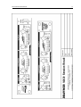
DRAWMER
MX30
DUAL GATED COMPRESSOR
OPERATORS MANUAL
CONTENTS
SAFETY CONSIDERATIONS
page 1
INTRODUCTION
page 2
INSTALLATION
•
Audio Connections
•
Power Connection
page 3
page 3
page 5
CONTROL DESCRIPTIONS
•
Gate / Expander
•
Compressor
•
Limiter
•
Linking
page
page
page
page
page
OPERATION
page 9
IF A FAULT DEVELOPS
CONTACTING DRAWMER
page 10
page 10
TECHNICAL SPECIFICATION
BLOCK DIAGRAM
SESSION RECALL SHEET
page 11
page 12
page 13
i
6
6
7
8
8
COPYRIGHT
This manual is copyrighted © 2011 by Drawmer Electronics, Ltd. With all rights
reserved. Under copyright laws, this manual may not be duplicated in whole or in
part without the written consent of Drawmer.
ONE YEAR LIMITED WARRANTY
Drawmer Electronics Ltd., warrants the Drawmer MX30 audio processor to
conform substantially to the specifications of this manual for a period of one year
from the original date of purchase when used in accordance with the specifications
detailed in this manual. In the case of a valid warranty claim, your sole and
exclusive remedy and Drawmer’s entire liability under any theory of liability will be
to, at Drawmer’s discretion, repair or replace the product without charge, or, if not
possible, to refund the purchase price to you. This warranty is not transferable. It
applies only to the original purchaser of the product.
For warranty service please call your local Drawmer dealer. Alternatively call
Drawmer Electronics Ltd. at +44 (0)1709 527574. Then ship the defective product,
with transportation and insurance charges pre-paid, to Drawmer Electronics Ltd.,
Coleman Street, Parkgate, Rotherham, S62 6EL UK. Write the RA number in large
letters in a prominent position on the shipping box. Enclose your name, address,
telephone number, copy of the original sales invoice and a detailed description of
the problem. Drawmer will not accept responsibility for loss or damage during
transit.
This warranty is void if the product has been damaged by misuse, modification or
unauthorised repair.
THIS WARRANTY IS IN LIEU OF ALL WARRANTIES, WHETHER ORAL OR
WRITTEN, EXPRESSED, IMPLIED OR STATUTORY. DRAWMER MAKES NO
OTHER WARRANTY EITHER EXPRESS OR IMPLIED, INCLUDING, WITHOUT
LIMITATION, ANY IMPLIED WARRANTIES OF MERCHANTABILITY, FITNESS
FOR A PARTICULAR PURPOSE, OR NON-INFRINGEMENT. PURCHASER’S
SOLE AND EXCLUSIVE REMEDY UNDER THIS WARRANTY SHALL BE REPAIR
OR REPLACEMENT AS SPECIFIED HEREIN.
IN NO EVENT WILL DRAWMER ELECTRONICS LTD. BE LIABLE FOR ANY
DIRECT, INDIRECT, SPECIAL, INCIDENTAL OR CONSEQUENTIAL DAMAGES
RESULTING FROM ANY DEFECT IN THE PRODUCT, INCLUDING LOST
PROFITS, DAMAGE TO PROPERTY, AND, TO THE EXTENT PERMITTED BY
LAW, DAMAGE FOR PERSONAL INJURY, EVEN IF DRAWMER HAS BEEN
ADVISED OF THE POSSIBILITY OF SUCH DAMAGES.
Some states and specific countries do not allow the exclusion of implied warranties
or limitations on how long an implied warranty may last, so the above limitations
may not apply to you. This warranty gives you specific legal rights. You may have
additional rights that vary from state to state, and country to country.
In the interests of product development, Drawmer reserve the right to modify or
improve specifications of this product at any time, without prior notice.
ii
MX30 OPERATORS’ MANUAL
1
DRAWMER MX30
Dual Gated Compressor
SAFETY CONSIDERATIONS
CAUTION - MAINS FUSE
TO REDUCE THE RISK OF FIRE REPLACE THE MAINS FUSE ONLY WITH
THE SAME TYPE, WHICH MUST BE A CLASS 3, 250 VOLT, TIME DELAY
TYPE, RATED AT 32mA WHERE THE MAINS INPUT IS SET TO 230 VOLTS
AC. AND 63mA WHERE THE MAINS INPUT VOLTAGE IS 115 VOLTS AC.
ALL FUSES MUST COMPLY WITH IEC 127-2.
THE FUSE BODY SIZE IS 20mm x 5mm.
CAUTION - MAINS CABLE
DO NOT ATTEMPT TO CHANGE OR TAMPER WITH THE SUPPLIED MAINS
CABLE.
CAUTION - SERVICING
DO NOT PERFORM ANY SERVICING. REFER ALL SERVICING TO
QUALIFIED SERVICE PERSONNEL.
WARNING
TO REDUCE THE RISK OF FIRE OR ELECTRIC SHOCK DO NOT EXPOSE
THIS EQUIPMENT TO RAIN OR MOISTURE.
2
MX30 OPERATORS’ MANUAL
INTRODUCTION
The MX30 is a dual channel gate and compressor-limiter designed to fulfil the needs of
professional studio and live sound applications. It may be used in balanced systems at
+4dBu operating levels, or unbalanced at -10dBu.
In order to maximise flexibility while simplifying set up and operation, several new
design concepts have been incorporated. The compressor section combines aspects
of both the traditional ratio style compressor and the soft-knee approach, making it
equally adept at creative work and unobtrusive level control. The control layout
resembles that of a straight ratio style unit but the transition from unity gain to gain
reduction at the selected ratio is progressive and occurs over a nominal 10dB input level
range.
Traditionally, soft-knee compressors have been preferable for unobtrusive level control
where the original sound is to be changed as little as possible, whereas ratio type
compressors are generally considered more successful in creative applications or where
large amounts of gain reduction are required. By combining these two elements, the
MX30 is capable of outstanding results in a very wide range of studio and live sound
situations.
One of the perennial problems in using compression is that maximum system gain
occurs during extremely quiet passages or pauses which results in an increase in
background noise, the degree depending on how much compression is being used. The
accepted way of dealing with this problem is to include in the compressor, a separate
gate section with its own threshold control so that a low level gating action may be
applied to keep pauses clean. However, the problem with simple gates is that, even
when properly set up, they may unwittingly process low level sounds as they have no
means of identifying them from noise. On a vocal track, for example, this can lead to the
starts or endings of words being accidentally removed, especially if the singer has a
wide dynamic range.
The MX30 uses a proprietary Programme Adaptive gate circuit that varies its ratio
depending on the dynamics of the signal being processed. Because the onset of gating
is progressive, those low level signals most at risk will be treated to a lower ratio of
gating (like an expander) while the residual noise during pauses will be subjected to a
higher expansion ratio and will, in consequence, be attenuated more. The outcome is
a gate that requires less stringent setting up and is more tolerant of wanted sounds that
are only slightly above the residual noise floor.
A further feature of the MX30 is a peak limiter that allows the user to set an absolute
output signal level that will not be exceeded. If the peak limiter threshold is exceeded
for more than a few milliseconds, additional gain reduction will be applied to reduce the
overall signal level to within accepted limits without distortion. Once the peak has
passed, the system gain will return to normal over the period of about one second. This
facility is extremely valuable both in live sound applications, for driver protection, and
in digital recording where an absolute maximum recording level exists. Furthermore,
when overdriven, it can be used creatively to produce deliberate level pumping effects.
MX30 OPERATORS’ MANUAL
3
INSTALLATION
The MX30 is designed for standard 19" rack mounting and occupies 1U of rack space.
Avoid mounting the unit directly above power amplifiers or power supplies that radiate
significant amounts of heat. Fibre or plastic washers may be used to prevent the front
panel becoming marked by the mounting bolts.
AUDIO CONNECTIONS
Input and Output connections are provided for use at +4dBu via balanced XLRs or at
-10dBu via unbalanced jacks. It is permissible to use both +4dBu and -10dBu outputs
simultaneously. If unbalanced operation at +4dBu is required, simply connect the
unused terminal to Ground inside the XLR cable plugs. This applies to both inputs and
outputs. The wiring convention for XLR being: pin 1 Ground, pin 2 Hot and pin 3 Cold.
For use with unbalanced systems, the Cold pin 3 must be grounded at both input and
output XLRs.
Interference:
If the unit is to be used where it maybe exposed to high levels of
disturbance such as found close to a TV or radio transmitter, we
suggest that the unit be operated using the XLR connectors. The
screens of the signal cables should be connected to the chassis
connection on the XLR connector as opposed to connecting to
pin1. The MX30 fully conforms to the EMC standards.
Ground Loops:
If ground loop problems are encountered, never disconnect the
mains earth, but instead, try disconnecting the signal screen on
one end of each of the cables connecting the outputs of the MX30
to the patchbay. If such measures are necessary, balanced (XLR)
operation is recommended.
Level Conversion:
It is possible to apply an input to the MX30 at only one of the two
possible levels, say !10dB via the jack socket, and utilise both of
the output levels and cable options of !10dB and +4dB
simultaneously.
One useful example of this connection option would be if the unit
was used to process a keyboard - commonly these have an output
level of !10dB, and are terminated with jack sockets. It is feasible
using the MX30s dual output capability to use the !10dB jack input
to feed from the keyboard and the !10dB output onwards to the
amplifier, and the +4dB balanced XLR connector for a direct feed
to the mixing console. This removes the need for any DI box or
cable splitter. In this example, ground loop considerations may be
required.
4
MX30 OPERATORS’ MANUAL
AUDIO CONNECTION DIAGRAM
MX30 OPERATORS’ MANUAL
5
POWER CONNECTION
If, for some reason, the unit is to be operated at a mains input voltage which is different
to that as supplied, the following procedure must be carried out by a qualified technical
engineer.
1:
Disconnect the unit from the mains.
2:
Using a number 1 size pozidrive screwdriver, remove the seven
self-tapping screws that retain the top cover.
Accessing the internal power switch and fuse
3. Set the voltage rating and
replace the fuse.
4. Replace the cover.
6
MX30 OPERATORS’ MANUAL
CONTROL DESCRIPTION
Both channels of the MX30 are identical and may be used completely independently or
linked for stereo operation. In the linked mode, only the left-hand channel controls are
functional and serve as master controls, though the channel bypass switches remain
independent. In linked mode, the compressor / limiters, peak limiters and gates /
expanders of the two channels track together to avoid the inevitable image shifting that
would occur if the two channels of a stereo signal were treated independently.
GATE
Threshold:
This control sets the level below which gating starts to take place
and may be set in the range -70dB to +20dB. The red LED which
signifies signal below threshold, and green LED (signifying signals
above threshold) will indicate the gate activity. Note: because the
gate / expansion ratio varies with signal level, it is possible to
arrive at a situation where the two LEDs may show some action
when little or no perceived gain reduction is taking place.
This means that the gate Threshold may need to be set a little
higher than it would with a conventional gate and final setting is
best done by ear. The adaptive gating system used in the MX30
means, however, that setting up is not over-critical and the gating
action is far more progressive.
Release:
Either a fast or slow release time may be selected depending on
the material being processed. Fast release is achieved with the
switch out and Slow release with the switch depressed. Percussive
material with little or no reverb is best treated using the fast
release setting, whereas material with slow decays or a significant
amount of added reverberation will usually respond better to the
longer release setting.
MX30 OPERATORS’ MANUAL
7
COM PRESSOR
Threshold:
This control determines the input level above which gain reduction
will be applied and may be set in the range -40 to +20dB. Soft knee
compression takes place for signals exceeding the threshold level
by up to 10dB above which level, conventional 'ratio' compression
is applied.
Ratio:
Sets the final compression ratio that will be applied once the 10dB
'soft-knee' region is exceeded. The ratio may be continuously
adjusted from 1.2:1 to 4 (infinity):1 allowing the possibility of true
hard limiting.
Gain Reduction
Meter:
A nine segment LED bargraph meter continuously monitors the
gain reduction applied by the compressor/limiter over the range 0
to 30dB.
OUTPUT
Gain:
Input / Output
Level Meter:
The output level may be attenuated or amplified by up to 20dB to
compensate for level changes caused by compression and limiting.
This control comes before the Peak limiter detector and this fact
should be taken into account when setting the Peak limiter
threshold.
This is an eight-segment LED bargraph level meter that monitors
the level of the output signal over the range -20dB to +15dB with
reference to the selected (-10dBu or +4dBu) operating level. When
Bypass is enabled, this meter will show the level of the
unprocessed signal passing through the unit.
8
MX30 OPERATORS’ MANUAL
PEAK LIM ITER
Level:
Sets an absolute limit to the level that the output signal will not be
permitted to exceed. This limiter is very fast acting enabling it to
control any peaks without audible distortion. If the output signal is
so high as to cause the limiter to operate for more than 20mS, the
system gain is automatically reduced to bring the signal back
within range. The system gain is then returned to normal over a
period of approximately one second. The compressor Gain control
should be used to ensure that the peak limiter operates only rarely
if at all, if it is to be used purely for peak protection. Alternatively,
it may be deliberately driven into limiting to produce creative
effects.
Bypass:
This switch causes all signal processing for this channel to be
disabled. Normally the switch is used to compare the raw
unprocessed signal verses with any gating, compression and
limiting of the audio input.
LINKING
Master:
Depressing this switch configures the unit in stereo mode where
the left-hand channel controls act as master for both audio
channels, (except the Bypass buttons which always function for
their respective channels).
The same degree of gain reduction is applied to both audio
channels to prevent image shifting which would otherwise occur
whenever the left and right signal dynamics varied from each other
by any significant degree.
MX30 OPERATORS’ MANUAL
9
OPERATION
The unit should be connected in line with the signal to be processed via suitable insert
points. Ensure that the insert send and return level on your console matches the MX30
input/output sockets that are being used.
For single channel use, each channel may be considered as completely independent
and set up accordingly. For use with stereo signals, such as complete mixes or
submixes, the unit should be switched to Stereo Link mode and all setting up done using
the left-hand channel controls, except the Bypass buttons, which are always
independent.
Setting up is simpler if the Gate is initially turned off and the Peak Limiter threshold set
to maximum. This allows the compressor/limiter to be set up in isolation. The ratio
setting depends on how firmly the signal dynamics need controlling; as a rule, higher
ratios provide a higher degree of control but also tend to be more audible in operation
when high levels of gain reduction are required. The integral soft-knee feature of the
MX30 renders these effects far less pronounced, but this factor should still be taken into
consideration when setting up. In general, a higher compression ratio may be used than
on a conventional compressor without compromising the sound quality.
Setting up is now simply a matter of adjusting the Threshold control until the desired
amount of gain reduction occurs. This is judged partly by ear and partly by observing the
gain reduction meter. Usually, a maximum gain reduction of between 6dB and 10dB will
be adequate. If more gain reduction appears necessary, it is worth considering applying
a conservative degree of compression during recording and then further compression
while mixing.
Compressing during a mix does increase the subjective level of tape and other
background noises during pauses and quiet passages but, unless the noise
contamination is serious, the Gate section will be able to attenuate it to a very high
degree without compromising the wanted signal.
Compressors are often accused of dulling the sound being processed, and a little
explanation is needed to understand exactly why that is. What happens is that bass
sounds, which contain most of the energy in a typical piece of music, cause the
compressor to operate, and so any quieter, high frequency sounds occurring at the
same time as the bass sound will also be turned down in level. That is why the cymbals
and hi-hats in a heavily compressed drum track seem to dip in level whenever a loud
bass drum or snare drum beat occurs.
At this point, the Gate Threshold may be set up and you should try both release time
settings to see which is least obtrusive in operation. For all but sharp percussive
sounds, the longer setting is likely to give the best results. Set the threshold using a
piece of program material that contains pauses, and adjust the threshold to be as low
a dB level as possible while still attenuating the noise during pauses. Listen carefully
to how the sounds come in after the pauses and how cleanly they fade away again: if
you can hear the gate changing the sound in an unacceptable way, then the threshold
is probably set too high.
10
MX30 OPERATORS’ MANUAL
Because the Gate is self-adapting to the programme dynamics, it should be possible to
obtain far more satisfactory results than are possible with conventional gates. Similarly,
do not assume that because the gate threshold LEDs flicker during a piece of quiet but
wanted material that it is having a detrimental effect. When it first comes into play, the
ratio of expansion is very low, so trust your ears!
Finally, set the Gain control to give the required output level using the level meter to
guide you. Avoid running at very high output levels as this reduces the available amount
of signal headroom and could lead to distortion in extreme cases. Once the gain is
correct, set the Peak Limiter Level control so that the limiter LED only lights briefly on
extreme signal peaks. Alternatively, set the Peak limiter Level to the desired value and
then adjust the compressor Gain control to ensure minimum limiter activity.
If required, the Gate may be used on its own with the compressor and limiter functions
disabled. The Peak limiter has no separate on / off control, but turning the Level control
fully clockwise will prevent any unwanted limiter action. To effectively bypass the
compressor section turn the compressor Threshold up to its maximum of +20dB (fully
counter-clockwise), set the Ratio to its lowest setting of 1.2:1 and adjust the Gain to
approximately 0dB.
IF A FAULT DEVELOPS
For warranty service please call Drawmer Electronics Ltd. Or their nearest authorised
service facility, giving full details of the difficulty. On receipt of this information, service
or shipping instructions will be forwarded to you. No equipment should be returned
under the warranty without prior consent from Drawmer or their authorised
representative.
For service claims under the warranty agreement a service Returns Authorisation (RA)
number will be given. Write this RA number in large letters in a prominent position on
the shipping box. Enclose your name, address, telephone number, copy of the original
sales invoice and a detailed description of the problem.
Authorised returns should be prepaid and must be insured. All Drawmer products are
packaged in specially designed containers for protection. If the unit is to be returned,
the original container must be used. If this container is not available, then the equipment
should be packaged in substantial shock-proof material, capable of withstanding the
handling for the transit.
CONTACTING DRAWMER
Drawmer Electronics Ltd., will be pleased to answer all application questions to enhance
your usage of this equipment. Please address correspondence to:
Drawmer (Technical Help line) : Coleman St.: Parkgate : Rotherham : S62 6EL : UK
or, E-mail us on :
[email protected]
Drawmer dealers, Authorised service departments and other contact information can be
obtained from our web pages on
http://www.drawmer.com
MX30 OPERATORS’ MANUAL
11
TECHNICAL SPECIFICATIONS
(Measurements taken using +4dBu balanced XLR input where applicable)
INPUT IMPEDANCE
20KOhm (bal), 4KOhm (unbal)
MAXIMUM INPUT LEVEL
+21dBu
OUTPUT IMPEDANCE
50 Ohm (bal), 100 Ohm (unbal)
MAXIMUM OUTPUT LEVEL
+20dBu
BANDWIDTH
<10Hz to 36KHz -1dB
CROSSTALK
!94dB
<100dB
@ 10KHz
@ 1KHz
NOISE AT UNITY GAIN with Gate OFF
Wideband
22Hz - 22KHz
CCIR ARM
IEC A
Q-Pk CCIR
AV
!95dB
!101dB
!100dB
!102dB
!89dB
RMS
!95dB
!101dB
!98dB
!100dB
!87dB
DISTORTION
Typical Input
Unity Gain, +4dBu input
+14dBu input, 10dB Gain Red.
100Hz
1KHz
10KHz
< 0.03%
< 0.02%
<0.03%
< 0.2%
< 0.2%
< 0.2%
POWER REQUIREMENTS
115Volt or 230Volt at 50-60Hz, 9 W atts
FUSE RATING
T32mA
f or
230Volt,
T63mA
CONFORMING TO IEC 127-2
FUSE TYPE
20mm x 5mm, Class 3 Slo-Blo, 250Volt working
CASE SIZE
482mm (w) x 44mm (h) x 200mm (d)
WEIGHT (incl packaging)
3.2 Kgs
f or 115Volt
12
MX30 OPERATORS’ MANUAL
BLOCK DIAGRAM
MX30 OPERATORS’ MANUAL
13