1
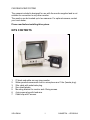
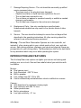
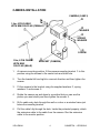
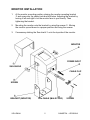
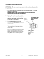
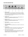
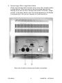
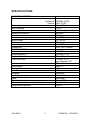
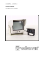
CAMSET5A --- VERSION II
OWNER'S MANUAL
CAR REAR VIEW SYSTEM
CAR REAR VIEW SYSTEM
The camera included is designed for use with the monitor supplied and is not
suitable for connection to any other monitor.
The monitor can be hooked up to two cameras. For optional camera, contact
your local dealer.
Please read before installing this system.
KITS CONTENTS
1.
2.
3.
4.
5.
6.
7.
5" black and white car rear view monitor
Water proofed camera with built-in microphone and 1.8m (female plug)
20m cable with male/male plug.
Sun shield plastic.
Mounting bracket for monitor and 4 fixing screws.
4-pin power plug with lead wire.
Cable clip and 2 screws.
VELLEMAN
1
CAMSET5A -- VERSION II
CAUTION
RISK OF ELECTRIC SHOCK DO NOT OPEN
CAUTION
TO REDUCE THE RISK OF ELECTRIC SHOCK, DO NOT REMOVE
COVER (OR BACK) NO USER-SERVICEABLE PARTS INSIDE.
REFER SERVICING TO QUALIFIED SERVICE PERSONNEL
The lighting flash with arrowhead symbol, within and
equilateral triangle, is intended to alert the user to the
presence of uninsulated "dangerous voltage" within the
product's enclosure that may be of sufficient magnitude to
constitute a risk of electric shock to persons.
The exclamation point within an equilateral triangle is
intended to alert the user to the presence of important
operating and maintenance (servicing) instructions in the
literature accompanying the appliance.
SAFETY INSTRUCTION
Before using this unit please read these operating instructions carefully.
Take special care to follow the warnings indicated on the unit itself as well as
the safety suggestions listed below. Keep them handy for future reference.
1.
Power source - The unit should be connected to power supply only of the
type described in the operating instructions or as marked on the unit.
2.
Water and Moisture - Do not use this unit near water.
3.
Heat - Do not install the unit near heat sources such as radiators, stoves,
heat registers, or other appliances that produce heat.
4.
Ventilation - The unit should be situated so that its location or position
does not interfere with its proper ventilation.
5.
Foreign Material - Care should be taken so that objects do not fall into
and liquids or not spilled into the unit.
6.
Surface - Place the unit on a flat, level surface.
VELLEMAN
2
CAMSET5A -- VERSION II
7.
Damage Requiring Service - The unit should be serviced by qualified
service personnel when :
- The power cord or the plug has been damaged.
- Objects have fallen or liquid has been spilled into the unit.
- The unit has been exposed to rain.
- The unit does not appear to operated normally or exhibits a marked
change in performance.
- The unit has been dropped or the enclosure is damaged.
8.
Replacement Parts - Use only manufacturer specified parts.
Unauthorised substitutions may result in fire, electric shock of other
hazards.
9.
Service - The user should not attempt to service the unit beyond that
described in the operating instructions. All other servicing should be
referred to an authorised service personnel.
Warning : The said Rear Observation Systems are to be used with, not
instead of, other viewing aids in your vehicle such as front, rear, and side
mirrors. Safe driving practices, alertness, and visual and physical fitness are
prerequisites for your driving safety. The Manufacturer shall not be held liable
for any accidents which may occur while operating this system.
INTRODUCTION AND FEATURES
This Hi-sharp Rear view system can lighter your worries on backing and
parking your car or truck. See and hear what's behind you and drive with
confidence.
Monitor :
► Dual camera input
► High Resolution - 500 TV lines
► Built-in speaker
► Free voltage from DC 12V to 24V
► Can be automatically activated when vehicle is shifted into reverse
Camera :
► With board lens for maximum viewing angle
► High resolution with 380 TV lines
► Water proofed case
► Built-in microphone
► Low light sensitivity - 0.1 lux
VELLEMAN
3
CAMSET5A -- VERSION II
CAMERA INSTALLATION
CAMERA (CAM13)
1.8m, 6 PIN CABLE
WITH MINI DIN PLUG (FEMALE)
WASHER
SPRING
WASHER
SCREW
20m, 6 PIN CABLE
WITH MINI
DIN PLUG (MALE)
BRACKET (CAMERA)
1.
At camera mounting position, fit the camera mounting bracket ! to this
position using the screws to the centre hole and slide hole.
2.
Turn the bracket left and right to a correct direction and then tighten the
screws.
3.
Fit the camera to the bracket using the supplied washers ", spring
washers # and screws $.
4.
Rotate the camera up and down to a position that you can see the
picture you want clearly and then tighten the screws $.
5.
Drill a cable entry hole through the wall or a door or a window frame just
below the mounting bracket.
6.
Pull the cable fully through the hole. Inside the protected property, attach
the extension cable to the cable from the camera. Run the extension
cable to the monitor position.
VELLEMAN
4
CAMSET5A -- VERSION II
MONITOR INSTALLATION
1.
At the monitor mounting position, placing the monitor mounting bracket
# and screw into the centre hole and slid holes. Adjusting the bracket by
turning it left and right to let the monitor face to you directly. Then
tightening the bracket.
2.
Mounting the monitor onto the bracket by using the screws ". Moving
the monitor up and down to a proper position and fixing the screws.
3.
If necessary sticking the Sun shield % onto the top side of the monitor.
MONITOR
POWER INPUT
SUN SHIELD
CABLE CLIP
SCREW
BRACKET (MONITOR)
VELLEMAN
20m CABLE (MALE PLUG)
5
SCREW
CAMSET5A -- VERSION II
CONNECTION TO MONITOR
IMPORTANT : Do not connect any camera to the monitor while monitor
is switched on.
1.
Plug the camera into the camera input DIN sockets marked A and B at
the back of the monitor.
Ensure that the arrow on the camera plug is at the top before
inserting the plug into the input sockets.
2.
Clipping the cables using the applied
cable clip and screw the cable clip into
the holes just beside the DIN sockets
GND
on the back of the monitor.
(Black)
3.
To Reverse Gear
Relay or Switch
(Blue)
Plug the power plug into into the
socked marked DC 12-24V at the back
of the monitor.
The connection of the power plug is
shown right.
Note that the Red wire with fuse holder
should be connected to car or truck
battery, and Blue wire to reverse gear
relay, Black wire to chassis ground.
VELLEMAN
6
To DC 12-24V
Fuse & Fuse
Holder
(Red)
CAMSET5A -- VERSION II
FUNCTION DESCRIPTION
%
Power-on switch
Push this button you can view the picture. Normally leave it unpushed
when the monitor is used in backing a truck or a car. When you shift the
gear in reverse, the unit will automatically display the picture of camera A
no matter the power is on or off.
"
Contrast control
Normally, it is not necessary to touch this control. When needed, turn it
clockwise to increase the contrast and vice versa.
#
Brightness control
Normally, it is not necessary to touch this control. When needed, turn it
clockwise to increase the contrast and vice versa.
$
Volume control
When needed, turn it clockwise to increase the volume.
!
A/B Camera switcher
This switch permits switching between picture viewed from camera A en
camera B.
&
Day/night switch
This switch permits brightness compensation during daylight. Unpush it
when the monitor is used in the day and leave it pushed at night.
'
A/B Camera picture signal input
One or both of the camera input connectors can be chosen to connect
cables from cameras. Please note that through these connectors the
needed DC power can be sent to the cameras.
VELLEMAN
7
CAMSET5A -- VERSION II
(
Normal image / Mirror image Select Switch
Please note that this switch has been set to mirror (Rev. Image) position
by manufacturer. When you want to view from behind while you are
backing a truck car, be sure to set this select switch to the (Rev. Image)
position. In this case, check to see if the image appearing on the display
is reversed right to left, just as it appears on a rear-view mirror.
Rear view of monitor showing input/output connections.
VELLEMAN
8
CAMSET5A -- VERSION II
SPECIFICATIONS
MONITOR CAMSET5A
Scanning frequency
Video input
Size of display
Scanning size
Resolution at centre
Shock
Vibration
Input voltage
Case
Operating temperature
Dimensions
CAMERA CAM13
Pick-up device
Scanning system
Number of pixels
Fixed focus lens
Horizontal 15625Hz -CCIRVertical 50Hz -CCIR1Vpp / 75Ω
5" CRT
86% min. (horizontal)
500 lines
6.8G
0 to 2000Hz
DC 12-24V
ABS plastic
0 to +40°C
143 x 190 x 136mm
1/3" CCD
625 lines -CCIR512 x 582 pixels
F3.6mm , F2.0,
open diagonal 130°
380 lines
1Vpp 75Ω
0.3lux
6.8G
0-2000Hz
DC 9.5-14V
zinc based
-10 to +50°C
80 x 65 x 55mm
CAM13
Horiz. resolution
Video output
Min. light illumination
Shock
Vibration
Input voltage range
Case
Operating temperature
Dimensions (with mounting bracket)
Optional extra camera
VELLEMAN
9
CAMSET5A -- VERSION II