1
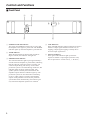
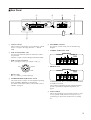
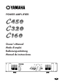
POWER AMPLIFIER
Owner’s Manual
Mode d’emploi
Bedienungsanleitung
Manual de instrucciónes
A
CLIP
B
SIGNAL
TEMP
PROTECTION
POWER
ON
OFF
M
Introduction
Thank you for purchasing a Yamaha C450/320/160 series power amplifier.
This series of audio amps was developed from Yamaha's wealth of experience in building PA
equipment and its tradition of careful attention to every detail of circuit design. These amps
feature high power and superb quality together with superior reliability and stability, guaranteeing the highest possible audio performance.
Main features of the C450/320/160 series
• Two types of input (balanced XLR type connectors and barrier strip), and barrier strip
for outputs are provided.
• Three operating modes are provided: STEREO mode in which CHANNEL A and B
operate independently, PARALLEL mode in which a mono source is output by two amp
systems, and BRIDGE mode in which the unit operates as a single high-power amplifier.
• A SIGNAL indicator and CLIP indicator is provided for each channel.
• The PROTECTION indicator shows the status of protective circuitry such as power-on/
off protection, output muting, and the DC detection circuit. The TEMP indicator warns
of heat sink overheating.
• Variable-speed low-noise fan(s) ensures high reliability even under demanding conditions.
• The C450/320/160 has implemented “EEEngine”, Yamaha’s epochal amp drive
technology to create an unrivaled high-efficiency drive.
The EEEngine’s energy-saver/low-heat-generation design has reduced power consumption to 50% or less, and reduced heat generation to 35% or less (in field applications,
compared to Yamaha’s previous models), and has lead to a reduction in energy cost and
to less-restrictive installation requirements related to heat generation.
This owner's manual covers the three models C450, C320 and C160. In order to take full
advantage of your power amp and enjoy long and trouble-free operation, please read this
owner's manual carefully before use.
IMPORTANT NOTICE FOR
THE UNITED KINGDOM
Connecting the Plug and Cord
WARNING: THIS APPARATUS MUST BE EARTHED
IMPORTANT: The wires in this mains lead are coloured in accordance with
the following code:
GREEN-AND-YELLOW
: EARTH
BLUE
: NEUTRAL
BROWN
: LIVE
As the colours of the wires in the mains lead of this apparatus may not
correspond with the coloured markings identifying the terminals in your
plug, proceed as follows:
The wire which is coloured GREEN and YELLOW must be connected to
the terminal in the plug which is marked by the letter E or by the safety earth
symbol or coloured GREEN and YELLOW.
The wire which is coloured BLUE must be connected to the terminal which
is marked with the letter N or coloured BLACK.
The wire which is coloured BROWN must be connected to the terminal
which is marked with the letter L or coloured RED.
* This applies only to products distributed by YAMAHA KEMBLE
MUSIC (U.K.) LTD.
Precautions
1. Avoid excessive heat, humidity, dust and vibration.
Keep the unit away from locations where it is likely to be
exposed to high temperatures or humidity — such as
near radiators, stoves, etc. Also avoid locations which
are subject to excessive dust accumulation or vibration
which could cause mechanical damage.
5. Make sure power is off before making or removing
connections.
Always turn the power OFF prior to connecting or
disconnecting cables. This is important to prevent damage to the unit itself as well as other connected equipment.
2. Ventilation
Allow a distance of 10 cm between the unit and the wall
so that heat generated from the unit will be released
effectively. Also, allow enough space between the unit
and other devices. If you mount the unit in an audio rack,
keep a space of 10 cm on the top panel, and a space of
1 cm to the side panel. Remove the rear panel of the rack
or open a vent hole. If heat release is inadequate, the unit
will retain heat inside the unit, which may cause a fire.
6. Handle cables carefully.
Always plug and unplug cables — including the AC cord
— by gripping the connector, not the cord.
3. Avoid physical shocks.
Strong physical shocks to the unit can cause damage.
Handle it with care.
7. Clean with a soft dry cloth.
Never use solvents such as benzine or thinner to clean
the unit. Wipe clean with a soft, dry cloth.
8. Always use the correct power supply.
Make sure that the power supply voltage specified on the
rear panel matches your local AC mains supply. Also
make sure that the AC mains supply can deliver more
than enough current to handle all equipment used in your
system.
4. Do not open the case or attempt repairs or modifications yourself.
This product contains no user-serviceable parts. Refer
all maintenance to qualified Yamaha service personnel.
Opening the case and/or tampering with the internal
circuitry will void the warranty.
Contents
Controls and Functions ............................................................. 2
Front Panel ........................................................................... 2
Rear Panel ........................................................................... 3
Modes: STEREO/PARALLEL/BRIDGE ................................ 4
SPEAKER IMPEDANCE...................................................... 4
Caution for Speaker Connection ............................................... 5
Rack Mounting .......................................................................... 6
Mounting in an EIA standard rack ....................................... 6
Mounting four or fewer amps in an open-backed rack ......... 6
Mounting five or more amps, or when (even with four or
fewer units) the back of the rack cannot be left open .......... 6
Portable Rack Mounting ...................................................... 7
Positioning the Housed Amplifier ......................................... 7
Specifications ............................................................................ 8
General Specifications ......................................................... 8
Block Diagram ...................................................................... 9
Dimensions .......................................................................... 9
Performance Graphs .......................................................... 10
Troubleshooting ...................................................................... 10
Controls and Functions
■ Front Panel
2
4
3
A
CLIP
B
SIGNAL
TEMP
PROTECTION
POWER
ON
OFF
1
1 POWER switch and indicator
This is the main POWER switch. Press to power ON
the amplifier. Press again to power OFF. The POWER
indicator lights up when the amplifier is powered ON.
2 TEMP indicator
When the temperature of the heat sink exceeds 85
degrees Celsius, this indicator will light red.
3 PROTECTION indicator
This red LED indicator lights up for approximately 3
seconds when the amplifier is powered ON, indicating
that the soft-start protection system is working. No
sound is output during soft-start up. If one of the
protection systems is activated during normal use, this
indicator lights up and no sound is output. The
speaker system is actually disconnected from the
amplifier outputs when this indicator lights up. The
protection systems are activated when overheating
occurs or a DC voltage is present at the amplifier
outputs. If the problem is corrected, the protection
systems deactivate automatically, this indicator goes
out, and normal amplifier operation is resumed.
2
5
4 CLIP indicators
These red LED indicators light up when the respective
channel’s output signal distortion exceeds 1% (i.e.
clipping). Output signal clipping is usually due to
excessive input signal levels.
5 SIGNAL indicators
These green LED indicators light up when the
respective channel’s output signal exceeds 2 Vrms.
This is equivalent to 1/2 watt into 8Ω, 1 W into 4Ω.
■ Rear Panel
2
3
INPUT
CHANNEL B
CHANNEL A
G
G
4
5
SPEAKERS
(BRIDGE)
(PARALLEL)
CHANNEL B
CHANNEL A
BRIDGE
STEREO
BRIDGE
20
15
20
10
25
30
40
15
10
25
30
6
3
6
3
40
∞ –dB 0
∞ –dB 0
CHANNEL B
CHANNEL A
STEREO
PARALLEL
1
1 Volume controls
These volume controls allow you to adjust the volume
level in 31 steps in the range between –∞ dB and
0 dB.
2 INPUTS (CHANNEL A, B)
Two types of balanced inputs for channels A and B
are provided.
Channel A input is used in Bridge and Parallel mode.
4 SPEAKERS terminals
For polarity in each mode, refer to the following
diagram.
• STEREO, PARALLEL mode
SPEAKERS
CHANNEL B
CHANNEL A
BRIDGE
STEREO
• XLR-3-31 type connectors
Pin 1–ground, pin 2–hot (+), and pin 3 cold (-).
Hot
1
2
Ground
• BRIDGE mode
3
Cold
• Barrier strip
Hot (+), Cold (-) and Ground (G).
3 STEREO/BRIDGE/PARALLEL switch
This slide switch is used to set the amplifier operating
mode: STEREO, BRIDGE or PARALLEL.
For details on the functionality of each mode, refer to
“Modes” on page 4.
SPEAKERS
CHANNEL B
CHANNEL A
BRIDGE
STEREO
In BRIDGE mode, the (-) terminals of CHANNELS
A and B are not used.
The minimum impedance for the connected speaker
system is specified in “Speaker Impedance” on
page 4.
5 GND terminals
This is the grounding screw terminal. If hum or noise
occurs, ground (earth) the unit via this jack, or try
connecting it to the chassis of the mixer or preamp,
etc.
3
■ Modes: STEREO/PARALLEL/BRIDGE
STEREO mode
In this mode, channels A and B operate independently
(as a conventional stereo amp).
The CHANNEL A input signal will be output from
the CHANNEL A output terminals, and the CHANNEL B input signal will be output from the CHANNEL B output terminals.
BRIDGE mode
In this mode, the CHANNEL A input signal will be
output from the BRIDGE output terminals. In this
case, use the front panel (channel) A volume control
to adjust the volume.
PARALLEL mode
In this mode, the CHANNEL A input signal will be
output from the output terminals of both channels A
and B. The CHANNEL B input terminals is not used.
The (channel) A and B volumes can be adjusted
independently.
■ SPEAKER IMPEDANCE
In STEREO and PARALLEL modes, the minimum
load (=speaker) impedance is 4Ω. In BRIDGE mode it
is 8Ω.
Make sure that the impedance does not fall below this
specified impedance.
STEREO mode connections
BRIDGE mode connections
SPEAKERS
CHANNEL B
SPEAKERS
CHANNEL A
CHANNEL B
CHANNEL A
BRIDGE
STEREO
BRIDGE
STEREO
BRIDGE
BRIDGE
Set to STEREO
Set to BRIDGE
STEREO
PARALLEL
MAX. OUTPUT 450W/4Ω (STEREO)
MAX. OUTPUT 900W/8Ω (BRIDGE)
–
+
4Ω min.
+
–
4Ω min.
PARALLEL mode connections
SPEAKERS
CHANNEL A
BRIDGE
STEREO
BRIDGE
Set to PARALLEL
STEREO
PARALLEL
MAX. OUTPUT 450W/4Ω (STEREO)
MAX. OUTPUT 900W/8Ω (BRIDGE)
–
+
4Ω min.
+
–
4Ω min.
Speaker System
4
PARALLEL
MAX. OUTPUT 450W/4Ω (STEREO)
MAX. OUTPUT 900W/8Ω (BRIDGE)
–
+
8Ω min.
Speaker System
Speaker System
CHANNEL B
STEREO
Caution for Speaker Connection
1. Turn off the POWER switch.
2. Remove the cover attachment screw(s) and remove
the protective cover from the speaker terminals.
Screw
3. After removing approx. 15 mm of insulation from the
ends of the speaker cables, bind the bare ends of the
speaker wires in the corresponding speaker terminals
and tighten the terminals to securely clamp the wires.
Refer to page 3 for speaker porality.
• Speaker fuse
The output capacity of your amplifier is very high:
460 W+460 W (8Ω) in stereo and 1240 W (8Ω) in
monaural on the C450; 340 W+340 W (8Ω) in stereo
and 880 W (8Ω) in monaural on the C320; 160
W+160 W (8Ω) in stereo and 400 W (8Ω) in monaural on the C160. Be sure to use a speaker system that
has sufficient input capacity.
If the input capacity of your speaker system is lower
than the rated output of the power amplifier, you can
protect your speakers by connecting a fuse serially
between the speaker and amplifier as shown below.
Speaker system
Power amplifier
_ +
+
_
15mm*
Fuse
Use the following formula to determine the fuse
capacity according to the speaker’s input capacity.
Po = I R → I = Po/R
2
* Shown actual size.
At this time make sure that the bare ends of the
speaker cables do not extend from the terminals in
such a way that they touch the chassis.
P0 [W] : Speaker’s continuous input capacity (noise
or RMS)
R [Ω] : Speaker’s nominal impedance
I [A] : Required fuse capacity
ex.)
Speaker’s continuous input capacity : 100 W
Speaker’s impedance : 8Ω
I = 100/8
In this example, the required fuse capacity is calculated as 3.5 [A].
Wire should not
touch the chassis.
• Speaker cable
If you use a long speaker cable, use as thick a cable as
possible to prevent deterioration of the damping factor
or power loss inside the cable.
4. Reattach the protective cover over the speaker
terminals.
5
Rack Mounting
■ Mounting in an EIA standard rack
If multiple high-power amp units are mounted in a rack with poor ventilation, the heat from the amps will cause the
interior of the amp to become very hot, causing the performance of the amps to be impaired. When mounting amps in
a rack, you must make provision for ventilation so that the heat can escape.
When mounting amps in a rack, please attach ventilation panels above and below the amp to allow air circulation.
When doing so, it is necessary for 35% or more of the entire surface area of a 1U size panel to be open.
Air circulation will be even better if the top surface of the rack has ventilation openings.
Ventilation panel
Yamaha provides an optional 1U-size ventilation panel VP1.
44
480
Unit: mm
■ Mounting four or fewer amps in
an open-backed rack
Install the ventilation panel above the amps, as shown
in the following figure.
Ventilation panel
(attach to the front
or rear of the rack)
6
■ Mounting five or more amps, or
when (even with four or fewer
units) the back of the rack cannot
be left open
Install ventilation panels above and below each amp,
as shown in the following figure.
■ Portable Rack Mounting
The amplifier intakes cool air through the front panel and exhausts warm air out the rear panel. When mounting
amplifiers in a portable rack, make sure the rear panel is completely open for ventilation.
(Side View)
(Rear View)
Completely open
Front
Air intake
INPUT
Air exhaust
CHANNEL B
CHANNEL A
G
G
SPEAKERS
(BRIDGE)
(PARALLEL)
CHANNEL B
CHANNEL A
STEREO
BRIDGE
BRIDGE
20
15
20
10
25
30
6
3
40
15
10
25
STEREO
PARALLEL
30
6
3
40
∞ –dB 0
∞ –dB 0
CHANNEL B
CHANNEL A
■ Positioning the Housed Amplifier
Place the case so that the ventilation airflow paths are not blocked.
Front
Less than 10 cm
Front
NO
NO
7
Specifications
■ General Specifications
C450
C320
C160
8Ω/STEREO
4Ω/STEREO
8Ω/BRIDGE
460 W + 460 W
620 W + 620 W
1240 W
340 W + 340 W
440 W + 440 W
880 W
160 W + 160 W
200 W + 200 W
400 W
1 kHz
0.05%
8Ω/STEREO
4Ω/STEREO
8Ω/BRIDGE
520 W + 520 W
720 W + 720 W
1440 W
370 W + 370 W
520 W + 520 W
1040 W
175 W + 175 W
230 W + 230 W
460 W
1 kHz, 20 ms, no clip
2Ω/STEREO
1300 W + 1300 W
950 W + 950 W
350 W + 350 W
Power Output Level (Rated Power)
20 Hz~20 kHz
0.05%
Power Bandwidth
Half Power, 0.1%
Total Harmonic Distortion (THD + N)
20 Hz~20 kHz, Half Power
4~8Ω/STEREO
8Ω/BRIDGE
Frequency Response
4~8Ω/STEREO
8Ω/BRIDGE
Damping factor
1 kHz, 8Ω
Input Impedance
SN Ratio
0.05%
10 Hz~50 kHz, +0, –1 dB
Intermodulation distortion (IMD)
7 kHz: 60 Hz, 1: 4, Half Power
Residual Noise
10 Hz~40 kHz
0.05%
200
30 kΩ/Balance, 15 kΩ/Unbalanced
Vol. min.
Input 600Ω shunt
Channel Separation
Slew Rate
8Ω full swing
12.7 kHz LPF
IHF-A network
–75 dB
12.7 kHz LPF
IHF-A network
105 dB
Half Power, 8Ω, Vol. max.
input 600Ω shunt
STEREO
BRIDGE
101 dB
65 dB, 20 Hz~20 kHz
75 dB, 1 kHz
>30 V/µ sec
>50 V/µ sec
Sensitivity (Vol. max.) Rated Power into 8Ω
+5.7 dB
Voltage Gain (Vol. max.)
32.1 dB
+4.2 dB
+1.2 dB
Controls
Front Panel
Rear Panel
POWER switch (Push on/Push off)
Volume (31 position dB calibrated)
Mode switch (STEREO/BRIDGE/PARALLEL)
Connectors
Input
Barrier strip terminal
XLR-3-31 type
Barrier strip terminal
Output
Indicators
POWER
TEMP
PROTECTION (mute)
CLIP
OUTPUT SIGNAL
Protection Circuits
(heatsink temp ≥ 85°C)
×2
×2
POWER switch ON/OFF, Muting, DC detection
TEMP (heatsink temp ≥ 95°C)
PC limiter
RL ≤ 1Ω
Fan Circuits
Low speed (50°C), Variable, High speed (70°C)
Power Requirements
United States & Canada
Europe
Other
120 V, 60 Hz
230 V, 50 Hz
240 V, 50 Hz
Power Consumption
500 W/650 VA
Dimensions (W × H × D)
480 × 103.5 × 455 mm
Weight
16 kg
Options
Ventilation panel: VP1
0 dB=0.775 Vrms, Half Power=1/2 Power Output Level (Rated Power)
Specifications subject to change without notice.
8
104 dB
400 W/500 VA
15 kg
200 W/250 VA
12 kg
■ Block Diagram
SIGNAL
Ach Power Amp
CHANNEL A
CHANNEL A
(BRIDGE)
(PARALLEL)
CHANNEL A
PC Limiter
G
CLIP
Temperature
Sensor
(Heat Sink)
INPUT
Protection
Circuit
PROTECTION
TEMP
SPEAKERS
CLIP
G
SIGNAL
CHANNEL B
PARALLEL
BRIDGE
STEREO
CHANNEL B
Bch Power Amp
CHANNEL B
PC Limiter
292
45
4.4
55.2
D:455
379.6
61.2
26
■ Dimensions
424
308
15.5
H:103.5
88
W:480
Unit: mm
9
■ Performance Graphs
Mode:STEREO
Both ch Driven
RL=4Ω, f=1kHz
C450
1k
100
20
5k
Power Consumption [W]
Power Consumption [W]
5k
1
10
100
1k
1k
100
20
1
Output Power [W]
10
100
1k
Output Power [W]
Mode:STEREO
Both ch Driven
RL=4Ω, f=1kHz
C160
5k
Power Consumption [W]
Mode:STEREO
Both ch Driven
RL=4Ω, f=1kHz
C320
1k
100
20
1
10
100
1k
Output Power [W]
Troubleshooting
The following table lists the main causes of abnormal operation and the corrective measures required, as well as the
protective circuit operation in each case.
Indicator
CLIP indicator lights.
TEMP indicator lights.
PROTECTION indicator
lights.
10
Probable Cause
Remedy
Protection Circuit
There is a short at a speaker
terminal, amplifier terminal,
or wire.
Locate and correct the cause
of the short.
The amplifier load is excessive.
Use a speaker system with
an impedance of at least 4Ω
(stereo) or 8Ω (bridge).
The heat sink temperature
has exceed 85˚C.
Check the ventilation slots,
and improve the airflow
around the amplifier.
Warning by the TEMP
indicator.
The heat sink temperature
has exceeded 95˚C.
Check the amplifier ventilation conditions and take
appropriate measures to
improve airflow around the
amplifier.
The thermal protection circuit
operates to protect the power
transistors.
A DC voltage of ±2 V or
greater was generated in the
power amplifier’s output
circuit.
Consult your dealer or
nearest Yamaha service
center.
The relay operates to protect
the speaker system.
The PC limiter circuit
operates to protect the power
transistors.