1
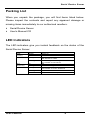
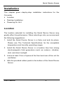
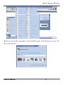
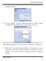
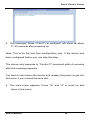
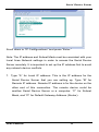
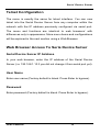
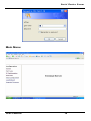
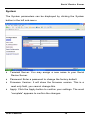
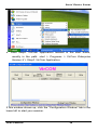
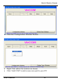
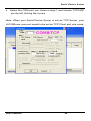
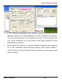
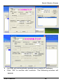
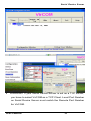
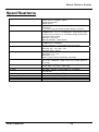
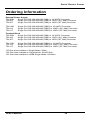
RS-232/422/485 to Copper or Fiber
Ethernet Converter
User’s Manual
Serial Device Server
Table Of Contents
TABLE OF CONTENTS ....................................... 1
INTRODUCTION .................................................. 3
PRODUCT OVERVIEW ........................................... 3
PRODUCT FEATURES ........................................... 3
PACKING LIST ..................................................... 4
LED INDICATORS ................................................ 4
INSTALLATION.................................................... 5
LOCATION ........................................................... 5
DESKTOP INSTALLATION....................................... 6
POWER ON UNIT ................................................. 6
CONFIGURATION................................................ 7
INITIAL SERIAL PORT CONFIGURATION .................. 7
SERIAL PORT CONFIGURATION ............................. 7
TELNET CONFIGURATION.................................... 13
WEB BROWSER ACCESS TO SERIA DEVICE SERVER
........................................................................ 13
Serial Device Server IP Address............... 13
User Name.................................................. 13
Password ................................................... 13
Main Menu .................................................. 14
System........................................................ 15
Port Type .................................................... 16
IP Configuration......................................... 17
Operation.................................................... 18
Save Configuration.................................... 19
Load Default............................................... 20
Upgrade Firmware ..................................... 21
User’s Manual
1
Serial Device Server
VIRCOM INSTALLATION ...................................... 22
SPECIFICATIONS.............................................. 33
ORDERING INFORMATION .............................. 35
User’s Manual
2
Serial Device Server
Introduction
Product Overview
This Serial Device Server features complete Ethernet and TCP/IP
network support that allows equipment with RS-232/422/485
connectors to connect to LAN-based TCP/IP networks.
Product Features
y
Complies with EIA/TIA and IEEE Standards.
y
Supports 4 wires full duplex asynchronous serial data
y
Supports
transmission (RS-422/485).
2
wires
half-duplex
asynchronous
serial
data
transmission (RS-485).
y
Supports serial port asynchronous data rates up to 230.4 kbps.
y
Extended distance up to 1.2 km (24AWG) via RS-422/485.
y
Extended distance up to 100 meters via Ethernet Cat. 3/4/5
cables.
y
Extended distance up to 2 km via Ethernet multi-mode fiber optic
y
Extended distance up to 75 km via Ethernet single-mode fiber
cable.
optic cable.
y
Supports auto-negotiation of speed and duplex mode on
Ethernet copper port.
y
3-in-1 RS-232/422/485 serial interfaces.
y
Terminator feature improves signal quality and distance.
y
Automatically rebuilds connection after power restart.
y
Setup and management via serial interface.
User’s Manual
3
Serial Device Server
Packing List
When you unpack the package, you will find items listed below.
Please inspect the contents and report any apparent damage or
missing items immediately to our authorized resellers.
y
Serial Device Server
y
User’s Manual CD
LED Indicators
The LED indicators give you instant feedback on the status of the
Serial Device Server:
LEDs
PWR
(Power)
LNK/ACT
State
Steady
Off
Steady
Flashing
STA
(STATUS)
FDX
On
Blinking
Steady
Flashing
Off
User’s Manual
Indication
Power on
Power off
Valid network connection established
LNK stands for LINK
Transmitting or receiving data
ACT stands for ACTIVITY
Idle
Active / Running
Connection in full duplex mode
FDX stands for FULL-DUPLEX
Collision occurred
Connection in half-duplex mode
4
Serial Device Server
Installation
This chapter gives step-by-step installation instructions for the
Converter.
y
Location
y
Desktop Installation
y
Powering On Unit
Location
The location selected for installing the Serial Device Server may
greatly affect its performance. When selecting a site, we recommend
the following suggestions:
1. Install the Serial Device Server in a fairly cool and dry place.
Please see The Technical Specifications for the acceptable
temperature and humidity operating ranges.
2. Install the Serial Device Server in a location free from strong
electromagnetic field generators (such as motors), vibration,
dust, and direct sunlight.
3. Leave at least 10cm of space at the front and rear of the unit for
ventilation.
4. Affix the provided rubber pads to the bottom of the Serial Device
Server.
User’s Manual
5
Serial Device Server
Desktop Installation
Follow the instructions listed below to install the Serial Device Server
in a desktop environment.
1. Place the Serial Device Server in a clean, flat, and safe position
that has easy access to AC power.
2. Affix the four self-adhesive rubber pads to the bottom of the
Serial Device Server.
3. Apply AC power to the Serial Device Server (The green PWR
LED should light up).
4. Connect cables from the network partner devices to the ports on
the front panel (The green LNK LED should light up).
Power On Unit
Serial Device Server uses an external power supply.
1.
DC jack: Connect the supplied AC to DC power adapter to the
receptacle on the Serial Device Server. Connect the power cord
to the AC to DC power adapter and attach the plug into a
standard AC outlet with the appropriate AC voltage.
2.
Terminal Block: Connect the DC power wires directly into the
terminal block located at the Ethernet port side of the device.
Please pay attention to the porality of the power connection.
Connect the ground terminal (G) to chasis ground if it is
available.
3.
Turn on power supply. As the device is powered on, verify that
the Power LED lights up. If not, check whether the power wires
are connected correctly.
User’s Manual
6
Serial Device Server
Configuration
The Serial Device Server can be set up directly through its serial port.
After the initial serial port setup, you may also configure it remotely
through a telnet program or web browser.
Initial Serial Port Configuration
The initial set-up of Serial Device Server is done through the unit’s
serial port. Prior to following the instructions listed below for
HyperTerminal Configuration, make sure that the Serial Device
Server is connected to a computer through a serial cable.
(Note: the Serial Device Server is preset with a factory default IP
address 192.168.1.10; that must be changed to a valid and unique
local address. It is important to do this so that your Serial Device
Server doesn’t conflict with other devices with the same default IP
address. This will be done in the following steps)
Serial Port Configuration
To configure Serial Device Server through serial port, you will need
to run HyperTerminal.
1. Open HyperTerminal in Windows from the Start menu. It’s
usually under Accessories/Communications
User’s Manual
7
Serial Device Server
Enter a name (for example, Terminal Server) and choose an icon for
the connection.
User’s Manual
8
Serial Device Server
2. In “Connect To” pick a local com port for “Connect using” (for
example, COM 1)
3. In “Port settings”, set your “bits per second” to “9600.” Leave
everything else at default value. Click “apply”, then “ok”.
Note: You must set emulation to VT100 instead of auto-detect. You
can do this by going to “File -> Properties -> Settings -> Emulation.”
4. Make sure the Serial Device Server is connected to your
computer’s serial port before turning on the power. If it’s ok,
power on the device and the following screen will appear
shortly.
User’s Manual
9
Serial Device Server
5. The message “Press <Ctrl+C> to configure” will show up about
17-20 seconds after powering up.
Note: This is for the first time configuration only. If the device has
been configured before you can skip this step.
The device only responds to “Control C” command within 4 seconds
after this message appears.
You have to shut down the device and reapply the power to get into
this menu if you missed this time slot.
6. The main menu appears. Press “W” and “S” to scroll up and
down in the menu.
User’s Manual
10
Serial Device Server
Scroll down to “IP Configurations” and press “Enter.”
Note: The IP address and Subnet Mask must be consistent with your
Local Area Network settings in order to access the Serial Device
Server remotely. It is important to set up the IP address first to avoid
any network device conflicts.
7. Type “A” for Local IP address. This is the IP address for the
Serial Device Server that you are setting up. Type “B” for
Remote IP address. Remote IP address is for the device on the
other end of this connection. The remote device could be
another Serial Device Server or a computer. “C” for Subnet
Mask, and “D” for Default Gateway Address (Router).
User’s Manual
11
Serial Device Server
8. Go back to the main menu by pressing “Esc” and scroll to “Apply
Settings.” Press “Enter” to apply your new settings. “Done”
appears to confirm that the changes have been applied.
Proceed to “Save Settings”. Press “Enter” and you’re done setting
up the unique IP address for Serial Device Server.
We suggest that you use web access menu to change the serial
baud rate after the initial serial port set up.
User’s Manual
12
Serial Device Server
Telnet Configuration
The menu is exactly the same for telnet interface. You can now
telnet into the Serial Device Server from any computer within the
network with the IP address previously configured via serial port.
The menu and functions are identical to web browsers’ with
differences only in appearance. More menu items and configurations
will be explored in the next section using a Web Browser.
Web Browser Access To Seria Device Server
Serial Device Server IP Address
In your web browser, enter the IP address of the Serial Device
Server (i.e. 192.168.1.10 if you did not change it from serial port yet).
User Name
Enter user name (Factory default is blank. Press Enter to bypass).
Password
Enter password (Factory default is blank. Press Enter to bypass).
User’s Manual
13
Serial Device Server
Main Menu
User’s Manual
14
Serial Device Server
System
The System parameters can be displayed by clicking the System
button in the left sub-menu.
y
Terminal Server: You may assign a new name to your Serial
Device Server.
y
Password: Enter a password to change the factory default.
y
Firmware Version: It will show the firmware version. This is a
read only field, you cannot change this.
y
Apply: Click the Apply button to confirm your settings. The word
“complete” appears to confirm the changes.
User’s Manual
15
Serial Device Server
Port Type
y
Port Type: Choose a port type. You can choose one of three
modes: RS232, RS485-2wire, and RS485/RS422-4wire.
y
Data Rate: Choose the transmission rate.
y
Data Bits: Choose between 5, 6, 7, or 8 bits.
y
Stop Bits: Choose between 1 or 2 bits.
y
Parity: Choose between None/Odd/Even Parity bits.
y
Flow Control: Select the Flow control.
y
Refresh: Click the Refresh button to update the screen to the last
saved Port Type.
y
Apply: Click the Apply button and apply the new Port Type.
User’s Manual
16
Serial Device Server
IP Configuration
y
Local IP Address: The IP Address for the Serial Device Server.
This is usually done in the initial cofiguration via serial port. If
you change it here, you will lose your current connection. You
will need to use the new IP address to come back.
y
Remote IP Address: The IP address for the device on the other
side for the Serial Device Server to connect to.
y
Netmask: The Network Mask for your local area network.
y
Default Gateway: Enter the IP address of the default gateway or
y
Refresh: Click the Refresh button to update the screen with the
router of your local area network.
last saved IP Configuration.
y
Apply: Click the Apply button to apply the new IP Configuration.
User’s Manual
17
Serial Device Server
Operation
y
Operation mode: Choose the Server/Client mode. This is only
applicable in TCP protocol.
y
Protocol: Choose the Internet protocol. You may choose TCP or
UDP.
y
Local port Number: Pick an unassigned port number (for
example 2001). This number will be used by the device on the
other side for TCP/UDP communication.
y
Remote Port Number: Enter the port number of the device on the
other side for your Serial Device Server to connect to.
y
Auto-Disconnect Time: The amount of idle time in seconds
before Serial Device Server disconnects.
y
Apply: Click the Apply button to apply the new settings of
Operation.
y
Refresh: Click the Refresh button to update the screen with the
last saved Operation.
User’s Manual
18
Serial Device Server
Save Configuration
y
Click Save Configuration.
User’s Manual
19
Serial Device Server
Load Default
y
Click Load Default to reset the configuration to factory default.
y
Click “Ok” to confirm or “Cancel” to exit.
Note: The default IP address is 192.168.1.10
User’s Manual
20
Serial Device Server
Upgrade Firmware
y
Set up the TFTP server. Run the TFTP server program from the
host computer and store the new firmware file to the default
directory of the TFTP server program.
y
Click Upgrade firmware; enter TFTP Server IP Address and path
name (including the file name of the upgrading firmware) to
upgrade software.
User’s Manual
21
Serial Device Server
VirCom Installation
The Following Chapter explains how to install the “VirCom” Virtual
Device Driver software to connect your computer’s Ethernet port to a
Serial Device Server over an Ethernet-based local area network.
y
Make sure the Serial Device Server is connected to the same
network as the PC where you are installing VirCOM.
y
Install VirCOM from the software CD. Select the complete install
option.
User’s Manual
22
Serial Device Server
y
Go to setup from the Start Menu > Program > VirCom
Enterprise Version X > Step1. Install VirCom driver.
y
Select the com port to connect the driver. This cannot be a
physically existing com port or pre-occupied virtual com port.
User’s Manual
23
Serial Device Server
y
Click “OK” to confirm.
y
Click “Yes” to approve scanning every single serial port on your
computer.
User’s Manual
24
Serial Device Server
y
The “waiting for building channel” window shows up. Please
allow it to complete as it installs virtual serial ports for the Serial
Device Server.
y
If the above error appears, click “Continue Anyway”.
y
Reboot your PC as requested to complete step1.
User’s Manual
25
Serial Device Server
y
Start Step2. VirCom Application located in the start menu,
usually in the path: start > Programs > VirCom Enterprise
Version X > Step2. VirCom Application.
If this window shows up, click the “Configuration Window” tab in the
lower left to start your session.
User’s Manual
26
Serial Device Server
y
Click the “Configuration Window” Button.
y
Right Click within the window as shown
y
Click “Add COM” to add a new com port to your PC
User’s Manual
27
Serial Device Server
y
Select the COM port you chose in step 1 and choose TCP/UDP
port by left clicking the mouse.
Note: When your Serial Device Server is set as TCP Server, your
VriCOM new com port needs to be set as TCP Client and vice versa.
User’s Manual
28
Serial Device Server
y
If TCP client is selected, the VirCom needs a remote site IP
address which is the local address of your Serial Device Server.
You may directly key in the address or have VirCom search for
you if the computer is in the same local area network as the
Serial Device Server.
y
If you opted for VirCom to search, please highlight the targeted
IP of the intended Serial Device Server and press “Select”.
VirCom will list all the Serial Device Server in the same local
area network.
User’s Manual
29
Serial Device Server
y
VirCOM will automatically update your remote IP address.
y
Click “OK” to confirm and continue. The following window will
appear.
User’s Manual
30
Serial Device Server
y
WARNING: If your Serial Device Server is set as a TCP server,
you have to select VirCOM as a TCP Client. Local Port Number
on Serial Device Server must match the Remote Port Number
for VirCOM.
User’s Manual
31
Serial Device Server
If your Computer sets VirCOM-RJ45 as TCP Server, your Serial
Device Server must be set as TCP Client.
User’s Manual
32
Serial Device Server
Specifications
Applicable Standards
Fixed Ports
Max. Distance
Data Rate
Signals
Configuration
LED Indicators
Dimensions
Weight
Power
Operating Temperature
Storage Temperature
Humidity
Emissions
User’s Manual
IEEE 802.3 10Base-T
IEEE 802.3u 100Base-TX/FX
EIA/TIA RS-232E
EIA/TIA-574
1 x 10/100Base-TX RJ-45 type or 100Base-FX SC/ST
connector
1 x 9-Pin or 25-Pin D-sub female Serial connector
10/100Base-TX: 100meters (Cat. 3/4/5)
100Base-FX: 50 or 62.5/125µm multi-mode fiber
(1300nm) up to 2km, 9 or 10/125µm single-mode fiber
(1300nm) up to 75km
RS-232: 15 meters
RS422, RS485: 1,200 meters
10/100Base-TX: 10 or 100Mbps
100Base-FX: 100Mbps
Serial: 600 bps ~ 230.4 kbps (asynchronous)
RS-232: DCD, TxD, RxD, DTR, SG, DSR, RTS, CTS
RS-422: TX-, TX+, RX+, RXRS-485: Data-, Data+
Parity: None, even, odd
Data bits: 5, 6, 7, 8
Stop bits: 1, 2
Flow Control: None, RTS/CTS, Xon/Xoff
Per Unit: PWR
Per Port: LNK/ACT, FDX, STA (On is idle; Blink is
running)
80.3mm (W) × 109.2mm (D) × 23.8mm (H)
(3.16” (W) × 4.3” (D) × 0.94” (H))
0.8Kg (1.76lbs.)
DC Jack: 12VDC, Terminal Block: 12-24VDC
2.64W Max.
0°C ~ 45°C (32℉ ~ 113℉)
-10°C ~ 70°C (14℉ ~ 158℉)
5 ~ 95%, non-condensing
FCC part 15 Class A, CE Mark Class A, VCCI Class A
33
Serial Device Server
DB9 DCE female connector Pin assignments
Pin no.
RS-232
1
2
3
4
5
6
7
8
9
DCD
RxD
TxD
DTR
SG
DSR
RTS
CTS
–
User’s Manual
RS-422
(4 wires)
RS-485/RS422
(2 wires)
TXTX+
DataData+
RX+
RX-
RS-232
Signal names
Data Carrier Detect
Received Data
Transmitted Data
Data Terminal Ready
Signal Ground
Data Set Ready
Request to Send
Clear to Send
No Used
34
Serial Device Server
Ordering Information
External Power Supply
TS100RJ
Single Port RS-232/422/485 (DB9) to 10/100TX Converter
TS100C
Single Port RS-232/422/485 (DB9) to 100FX (SC, MM) Converter
TS100T
Single Port RS-232/422/485 (DB9) to 100FX (ST, MM) Converter
TS101RJ
TS101C
TS101T
Single Port RS-232/422/485 (DB25) to 10/100TX Converter
Single Port RS-232/422/485 (DB25) to 100FX (SC, MM) Converter
Single Port RS-232/422/485 (DB25) to 100FX (ST, MM) Converter
Terminal Block
TS130RJ
Single Port RS-232/422/485 (DB9) to 10/100TX Converter
TS130C
Single Port RS-232/422/485 (DB9) to 100FX (SC, MM) Converter
TS130T
Single Port RS-232/422/485 (DB9) to 100FX (ST, MM) Converter
TS131RJ
TS131C
TS131T
Single Port RS-232/422/485 (DB25) to 10/100TX Converter
Single Port RS-232/422/485 (DB25) to 100FX (SC, MM) Converter
Single Port RS-232/422/485 (DB25) to 100FX (ST, MM) Converter
*ST fiber also available in Single-Mode, 20Km.
*SC fiber also available in Single-Mode, 20/40/75Km.
*SC fiber also available in WDM Single-Mode, 20/40Km.
User’s Manual
35