1
OC276-A-1.qxp
03.11.25 9:04 AM
Page 1
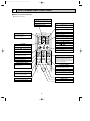
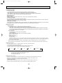
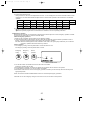
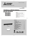
SPLIT-TYPE, HEAT PUMP AIR CONDITIONERS
No. OC276
REVISED EDITION-A
TECHNICAL & SERVICE MANUAL
Series PKH Wall Mounted
PKH18FL
PKH24FL
PKH30FL
PKH36FL
Revision:
●The wrong descriptions in REFRIGERANT
SYSTEM DIAGRAM have been modified.
(Page 18.)
●The wrong descriptions in WIRING DIAGRAM
have been modified.
(Page 19.)
●Restrictor valve and capillary tube have been
added to "Specifications" of heat exchanger.
(Page 48.)
●Please void OC276.
CONTENTS
1. FEATURES ·······························································2
2. PART NAMES AND FUNCTIONS ····························3
3. SPECIFICATIONS·····················································4
4. DATA ·········································································5
5. OUTLINES AND DIMENSIONS······························16
6. REFRIGERANT SYSTEM DIAGRAM ····················18
7. WIRING DIAGRAM ·················································19
8. OPERATION FLOW-CHART ··································20
9. MICROPROCESSOR CONTROL···························24
10. TROUBLESHOOTING ············································41
11. DISASSEMBLY PROCEDURE ·······························45
12. PARTS LIST ····························································48
˚F
˚C
STOP AMPM
SWING
START
MANUFAC
TU
RE
R
IFIED TO ARI A
RT
SC
CE
O
AIR
-CO
Y
G WITH
YIN
PL
M
NING
ITIO
ND
Remote controller
•
CE
EQ
UIP MENT
IFI
NS
C
IO
AIR ATIO N SE CT 40
S TA N DARD 2
RT
C
F
FAN
O
CHECK TEST
MODEL RUN
SELECT
NOT AVAILABLE
UNIT
AR
Indoor unit
•
[Models]
L IST ED
TM
US
OC276-A-1.qxp
1
03.11.25 9:04 AM
Page 2
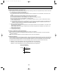
FEATURES
CHECK TEST
MODEL RUN
SELECT
FAN
˚F
˚C
STOP AMPM
SWING
START
NOT AVAILABLE
Indoor unit
Remote controller
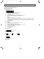
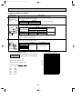
Models
Cooling capacity / Heating capacity
PKH18FL
PKH24FL
PKH30FL
PKH36FL
18,000
24,000
30,000
34,200
/
/
/
/
18,600
25,000
33,000
38,000
[25,100]
[31,500]
[40,500]
[45,500]
Btu/h
Btu/h
Btu/h
Btu/h
SEER
11.1
10.2
10.6
10.5
1. COMPACT DESIGN
The PKH series models have been downsized and now require such minimal wall space that they can even be installed
above windows.
2. LCD WIRELESS REMOTE CONTROLLER
The new wireless remote controller has a larger easy-to-read temperature display, and executes ON/OFF commands
and temperature settings with a press of the button.
3. AUTO FLAP SHUTTER
With a simple flick of the OFF switch the air outlet can be closed off with a shutter. The shutter also functions as a flap
during operation to adjust the air flow angle, with “Auto Angle 1” securing a comfortable air flow.
4. INSTALLATION : FAST AND EASILY ADAPTABLE
(1) Multi-directional piping
Multi directional drain and refrigerant piping radically improves flexibility in selecting installation layouts.
PKH18/24/30/36FL models boast refrigerant piping in 4 directions and drain piping in 2 directions.
(2) Back plate installation guide
The back plate installation guide gives clear instructions on installation positions. The enlarged back plate secures the
unit firmly to the wall, while the support piece which lifts the unit makes left side piping work much easier.
(3) Easily removable filter and convenient wireless remote controller
The presence of thumb screws on the filters means that the filters can be quickly and smoothly removed.
5. HIGH RELIABILITY AND EASY SERVICING
In addition to the self-diagnostic function, units are also equipped with a 3-minute time delay mechanism (cooling), an auto
restart function, an emergency operation function, a test run switch, etc., to assure high reliability and easy servicing.
6. NITROGEN GAS IS CHARGED TO INDOOR UNIT
Indoor unit and refrigerant pipes are charged with nitrogen gas (N2) instead of R22 before shipment from the factory.
2
OC276-A-1.qxp
03.11.25 9:04 AM
2
Page 3
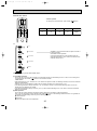
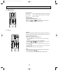
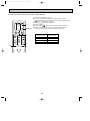
PART NAMES AND FUNCTIONS
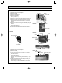
●Wireless remote controller
● When cover is open.
CHECK TEST RUN display
CHECK&TEST RUN display indicates that
the unit is being checked or test-run.
MODEL SELECT display
display
Blinks when model is selected.
Lights up while transmission to the indoor
unit is mode using switches.
88°F display
SET TEMP. display indicates desired temperature set.
CLOCK display
OPERATION MODE display
OPERATION MODE display
Operation mode display indicates which operation mode is in effect.
display
The vertical direction of air flow is indicated.
Displays the current time.
COOL
DRY
AUTO
FAN
HEAT
TIMER display
CHECK TEST
MODEL RUN
SELECT
FAN
˚F
˚C
STOP AMPM
Displays when in timer operation or when
setting timer.
“
SWING
START AMPM
NOT AVAILABLE
ON/OFF
“
TEMP
”“
” display
Displays the order of timer operation.
”“
” display
Displays whether timer is on or off.
display
button
FAN SPEED display indicates which fan
speed has been selected.
FAN
AUTO STOP
VANE
AUTO START
SET TEMPERATURE button sets any desired
room temperature.
ON/OFF button
The unit is turned ON and OFF alternately
each time the button is pressed.
MODE
CHECK LOUVER
h
FAN SPEED SELECT button
Used to change the fan speed.
MODE SELECT button
TEST RUN
SET
min
RESET
Used to switch the operation mode between
cooling, drying, fan.
TIMER CONTROL buttons
AUTO STOP (OFF timer): when this switch
is set, the air conditioner will be automatically stopped at the preset time.
AUTO START (ON timer): when this switch
is set, the air conditioner will be automatically started at the preset time.
CLOCK
h and min buttons
Buttons used to set the “hour and minute” of
the current time and timer settings.
LOUVER button
CHECK-TEST RUN button
This switch the horizontal fan motion ON
and OFF.
Only press this button to perform an inspection check or test operation.
Do not use it for normal operation.
(Not available for this model.)
CLOCK button
VANE CONTROL button
RESET button
Used to change the air flow direction.
SET button
3
OC276-A-1.qxp
3
03.11.25 9:04 AM
Page 4
SPECIFICATIONS
MODELS : PKH18FL, PKH24FL, PKH30FL, PKH36FL
Model
Item
Capacity
Cooling *1
Heating *1
Heating *2
Moisture removal
Power
Consumption
EER
SEER
HSPF
COP
Cooling *1
Heating *1
Heating *2
*1
Btu/h
Btu/h
Btu/h
Pints/h
kW
kW
kW
*1
*2
INDOOR UNIT MODELS
External finish
V,phase,Hz
Power supply
A
Max.fuse size (time delay)
A
Min.ampacity
F.L.A.
Fan motor
A(kW)
Booster heater
CFM
Dry
Airflow Hi-Lo
CFM
Wet
dB
Sound level Hi-Lo
in.
Unit drain pipe O.D.
in.
W
in.
D
Dimensions
in.
H
lb
Weight
OUTDOOR UNIT MODELS
External finish
V,phase,Hz
Power supply
A
Max.fuse size (time delay)
A
Min.ampacity
F.L.A.
Fan motor
Model (type)
R.L.A.
Compressor
L.R.A.
A(W)
Crankcase heater
Refrigerant control
Defrost method
dB
Sound level
in.
W
in.
D
Dimensions
in.
H
lb
Weight
REMOTE CONTROLLER
Control voltage (by built-in transformer)
Name
Charge
REFRIGERANT
L
Oil <Model>
REFRIGERANT PIPING
in.
Liquid
Pipe size
in.
Gas
Indoors
Connection
Outdoors
method
Height difference ft
Between the indoor
ft
Piping length
& outdoor units
PKH24FL
PKH18FL
PKH30FL
PKH36FL
24,000
30,000
25,000[30,500/31,500]
33,000[39,100/40,500]
14,700[20,200/21,200]
19,000[25,100/26,500]
7.0
9.1
2.36
3.12
2.37[3.97/4.27]
3.02[4.82/5.22]
1.92[3.52/3.82]
2.48[4.28/4.68]
10.2
9.6
10.2
10.6
6.8
7.1
3.1
3.2
2.2
2.2
PKH24FL
PKH30FL
Munsell 3.4Y 7.7/0.8
208/230,1,60
15
18,000
18,600[24,100/25,100]
10,700[16,200/17,200]
5.3
1.79
1.56[3.16/3.46]
1.34[2.94/3.24]
10.1
11.1
7.2
3.5
2.3
PKH18FL
12
0.5
7.6/8.4[1.6/1.9]
710-530
640-480
FK1:48 -41
34,200
38,000[44,100/45,500]
19,600[25,700/27,100]
10.5
3.44
3.54[5.34/5.74]
2.65[4.45/4.85]
9.9
10.5
6.9
3.1
2.2
PKH36FL
13
0.6
8.7/9.6[1.8/2.2]
990-780
890-700
FK1:49-44
FK1:50-46
1-1/16 (or 7/8)
55-1/8
66-5/32
9-1/4
13-3/8
57
PUH18EK
20
16
0.75
RH247NAB
12
37
0.11/0.12[23/28]
53
33-1/2
131
5 lbs 8 oz
0.52 <MS-56>
130
130
57
PUH24EK1
66
66
PUH30EK1
PUH36EK1
Munsell 5Y 7/1
208/230,1,60
20
30
30
16
20
22
0.65+0.65
0.75+0.75
0.75+0.75
NH33NBD
NH41NAD
NH47NAD
11.5
14.0
17.5
54
73
87
0.16/0.17[33/39]
0.16/0.17[33/39]
0.16/0.17[33/39]
Capillary tube
Reverse cycle
55
55
55
38-3/16
38-3/16
34-1/4
13-9/16
13-9/16
11-5/8
49-9/16
49-9/16
49-9/16
202
245
246
With indoor unit
Indoor unit-remote controller:DC12V. Indoor unit-outdoor unit:DC12V
R22
9 lbs 15 oz
10 lbs 2 oz
10 lbs 9 oz
1.2 <MS32N-1>
1.3 <MS32N-1>
Not supplied(optional parts)
1/2
1/2
3/8
3/4
3/4
5/8
Flared
Flared
164
164
164
164
NOTES : *1.Rating conditions (cooling)-indoor : 80˚FDB,67˚FWB outdoor : 95˚FDB,75˚FWB.
(heating)-indoor : 70˚FDB,60˚FWB outdoor : 47˚FDB,43˚FWB.
*2.Rating conditions (heating)-indoor : 70˚FDB,60˚FWB outdoor : 17˚FDB,15˚FWB.
*3.Heating capacity and power consumption in [ ] includes heater operation at 208/230V.
Operating range
Indoor intake air temperature
Outdoor intake air temperature
Maximum
95˚FDB,71˚FWB
115˚FDB
Cooling
Minimum
67˚FDB,57˚FWB
0˚FDB *
Maximum
80˚FDB,67˚FWB
75˚FDB,65˚FWB
Heating
Minimum
70˚FDB,60˚FWB
17˚FDB,15˚FWB
In case of the wind baffle is installed.
*
(In case of the wind baffle is not installed, the minimum temperature will be 23˚FDB.)
4
OC276-A-1.qxp
03.11.25 9:04 AM
4
Page 5
DATA
MODELS : PKH18FL, PKH24FL, PKH30FL, PKH36FL
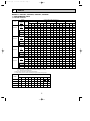
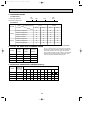
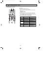
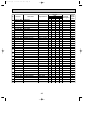
1. PERFORMANCE DATA
1) COOLING CAPACITY
Models
Models
Airflow
(CFM)
B.F
Outdoor intake air DB temperature(˚F)
IWB
(˚F)
75
85
95
105
115
TC
SHC
TPC
TC
SHC
TPC
TC
SHC
TPC
TC
SHC
TPC
TC
SHC
TPC
71
21.0
14.4
1.56
20.2
13.9
1.69
19.4
13.3
1.84
18.5
12.7
1.99
17.6
12.1
2.15
67
19.5
16.0
1.52
18.8
15.4
1.65
18.0
14.8
1.79
17.1
14.0
1.93
16.3
13.4
2.07
63
18.2
17.4
1.49
17.5
16.7
1.61
16.8
16.0
1.74
15.9
15.2
1.88
15.1
14.4
2.01
DB 75°F (50%RH) 62.5
18.1
15.5
1.49
17.4
14.9
1.61
16.6
14.3
1.74
15.8
13.6
1.87
15.0
12.9
2.00
DB 72°F (50%RH)
60
17.2
15.1
1.47
16.6
14.5
1.58
15.8
13.8
1.70
15.0
13.1
1.84
14.2
12.4
1.96
DB 70°F (50%RH)
59
16.8
14.5
1.46
16.2
14.0
1.57
15.5
13.4
1.69
14.6
12.6
1.83
13.9
12.0
1.94
71
27.9
16.1
2.05
26.9
15.5
2.23
25.8
14.9
2.43
24.6
14.2
2.63
23.4
13.5
2.84
67
26.1
18.5
2.01
25.1
17.8
2.18
24.0
17.0
2.36
22.9
16.3
2.55
21.7
15.4
2.73
63
710
0.16
PKH18FL
710
0.16
PKH24FL
24.3
20.5
1.97
23.4
19.7
2.12
22.4
18.9
2.30
21.3
18.0
2.47
20.1
17.0
2.65
DB 75°F (50%RH) 62.5
24.1
18.0
1.96
23.2
17.4
2.12
22.2
16.6
2.29
21.1
15.8
2.47
19.9
14.9
2.64
DB 72°F (50%RH)
60
23.0
17.6
1.94
22.1
16.9
2.09
21.1
16.2
2.25
20.1
15.4
2.41
18.9
14.5
2.58
DB 70°F (50%RH)
59
22.5
17.0
1.93
21.7
16.4
2.07
20.7
15.6
2.24
19.7
14.9
2.39
18.5
14.0
2.56
71
34.9
21.5
2.72
33.7
20.8
2.95
32.3
19.9
3.21
30.8
19.0
3.48
29.3
18.1
3.75
67
32.6
24.5
2.66
31.4
23.6
2.88
30.0
22.5
3.12
28.6
21.5
3.37
27.1
20.3
3.61
63
30.4
26.9
2.60
29.2
25.8
2.81
27.9
24.6
3.04
26.6
23.5
3.27
25.1
22.2
3.50
DB 75°F (50%RH) 62.5
30.2
23.8
2.59
29.0
22.9
2.80
27.7
21.9
3.03
26.3
20.7
3.26
24.9
19.6
3.49
DB 72°F (50%RH)
60
28.8
23.2
2.57
27.6
22.2
2.77
26.3
21.2
2.99
24.9
20.1
3.21
23.5
18.9
3.43
DB 70°F (50%RH)
59
28.2
22.4
2.56
27.0
21.5
2.76
25.7
20.4
2.98
24.4
19.4
3.19
22.9
18.2
3.41
71
39.8
23.0
3.00
38.4
22.1
3.25
36.8
21.2
3.54
35.1
20.2
3.83
33.4
19.3
4.13
67
37.1
26.3
2.93
35.7
25.3
3.17
34.2
24.3
3.44
32.6
23.1
3.71
30.9
21.9
3.98
63
34.7
29.3
2.87
33.3
28.1
3.10
31.9
26.9
3.35
30.3
25.6
3.61
28.7
24.2
3.86
DB 75°F (50%RH) 62.5
34.4
25.8
2.86
33.1
24.8
3.09
31.6
23.7
3.34
30.0
22.5
3.59
28.4
21.3
3.85
DB 72°F (50%RH)
60
32.8
25.1
2.82
31.5
24.1
3.04
30.1
23.0
3.28
28.5
21.8
3.52
26.9
20.6
3.76
DB 70°F (50%RH)
59
32.2
24.3
2.81
30.8
23.2
3.03
29.5
22.3
3.26
27.9
21.0
3.50
26.4
19.9
3.73
990
0.15
PKH30FL
990
0.14
PKH36FL
Notes 1. B.F. : Bypass Factor, IWB : Intake air wet-bulb temperature
TC : Total Capacity (x103 Btu/h), SHC : Sensible Heat Capacity (x103 Btu/h)
TPC : Total Power Consumption (kW)
2. SHC is based on 80˚FDB of indoor intake air temperature.
3. Cooling capacity correction factors and Refrigerant piping length (one way) range.
Refrigerant piping length (one way)
MODEL
25ft
40ft
55ft
70ft
85ft
100ft
115ft
130ft
PKH18FL
1.0
0.992
0.983
0.978
0.966
0.959
0.950
0.945
PKH24FL
1.0
0.981
0.968
0.952
0.940
0.925
0.913
PKH30FL
1.0
0.981
0.968
0.952
0.940
0.925
PKH36FL
1.0
0.981
0.968
0.952
0.940
0.925
150ft
164ft
0.900
0.886
0.874
0.913
0.900
0.886
0.874
0.913
0.900
0.886
0.874
5
OC276-A-1.qxp
03.11.25 9:04 AM
Page 6
2) HEATING CAPACITY
Models
PKH18FL
PKH24FL
PKH30FL
PKH36FL
Airflow IWB
(CFM) (˚F)
710
710
990
990
Auxiliary heater
208V
230V
Outdoor intake air WB temperature(˚F)
Models
15
25
35
45
55
65
CA
PC
CA
PC
CA
PC
CA
PC
CA
PC
CA
PC
CA
PC
75
12.1
1.20
14.1
1.34
16.3
1.49
18.7
1.65
21.4
1.83
23.7
1.99
5.5
1.6
70
12.4
1.16
14.4
1.29
16.7
1.44
19.1
1.59
21.8
1.76
24.1
1.91
65
12.7
1.11
14.7
1.24
17.0
1.38
19.5
1.53
22.2
1.69
24.5
1.83
6.5
1.9
75
16.3
1.82
18.9
2.03
21.9
2.27
25.2
2.51
28.8
2.77
32.8
3.01
5.5
1.6
70
16.6
1.76
19.4
1.96
22.4
2.19
25.7
2.42
29.3
2.67
33.3
2.90
65
17.0
1.69
19.8
1.89
22.9
2.10
26.2
2.32
29.9
2.56
33.9
2.78
6.5
1.9
75
21.5
2.32
25.0
2.59
28.9
2.89
33.2
3.20
38.0
3.53
43.2
3.86
6.1
1.8
70
21.9
2.24
25.5
2.50
29.6
2.78
33.9
3.08
38.6
3.40
43.7
3.72
7.5
2.2
65
22.5
2.15
26.1
2.40
30.2
2.68
34.6
2.96
39.4
3.26
44.6
3.56
75
24.7
2.71
28.7
3.04
33.3
3.39
38.2
3.75
43.7
4.14
49.6
4.49
6.1
1.8
70
25.3
2.62
29.4
2.93
34.1
3.26
39.0
3.61
44.5
3.98
50.4
4.28
7.5
2.2
65
25.9
2.53
30.1
2.82
34.8
3.14
39.9
3.47
45.4
3.83
51.3
4.14
Notes 1. IDB : Intake air dry-bulb temperature
CA : Capacity (x103 Btu/h), PC : Power Consumption (kW)
2. When booster heater is "on", total capacity and total power consumption should be added the figures described in
booster heater column.
•Booster heater ON : When the set temperature is higher than the room temperature by more than 5.4 deg.
•Booster heater OFF : When the set temperature is higher than the room temperature by less than 3.6 deg.
3. Heating capacity correction factors.
Refrigerant piping length (one way)
Models
Less than 100ft
100~130ft
130~164ft
PKH18FL
1.00
0.995
0.990
PKH24FL
1.00
0.995
0.990
PKH30FL
1.00
0.995
0.990
PKH36FL
1.00
0.995
0.990
6
OC276-A-1.qxp
03.11.25 9:04 AM
Page 7
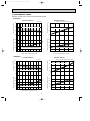
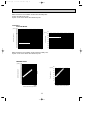
2. PERFORMANCE CURVE
NOTES : A point on the curve shows the reference point.
<PKH18FL>
COOLING CAPACITY
HEATING CAPACITY
Indoor intake air WB temperature ( F)
18
71
67
63
12
Does not include booster heater (1.9kW)
30
65
70
75
24
Indoor intake air DB temperature ( F)
18
12
2.5
71
67
63
2.0
1.5
Indoor intake air WB temperature ( F)
1.0
023
32 35
45
55
65(67) 75
85
95
105
Total power consumption (kW)
Total capacity (x10 3 Btu/h)
Total power consumption (kW)
24
Total capacity (x10 3 Btu/h)
SHF=0.82
30
2.5
75
70
65
2.0
1.5
Indoor intake air DB temperature ( F)
1.0
15
115
Outdoor intake air DB temperature ( F)
25
35
45
55
65
Outdoor intake air WB temperature ( F)
<PKH24FL>
COOLING CAPACITY
30
24
Indoor intake air WB temperature ( F)
71
67
63
18
Total capacity (x10 3 Btu/h)
36
Total capacity (x10 3 Btu/h)
HEATING CAPACITY
SHF=0.71
Indoor intake air DB temperature ( F)
30
65
70
75
24
18
12
3.0
71
67
63
2.5
2.0
Indoor intake air WB temperature ( F)
1.5
023
32 35
45
55
65(67) 75
85
95 105
Outdoor intake air DB temperature ( F)
115
7
Total power consumption (kW)
Total power consumption (kW)
12
Does not include booster heater (1.9kW)
35
3.0
75
70
65
2.5
2.0
Indoor intake air DB temperature ( F)
1.5
15
25
35
45
55
Outdoor intake air WB temperature ( F)
65
OC276-A-1.qxp
03.11.25 9:04 AM
Page 8
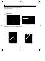
NOTES : A point on the curve shows the reference point.
<PKH30FL>
COOLING CAPACITY
SHF=0.75
Total capacity(x10 3 Btu/h)
48
36
30
71
67
63
24
indoor intake air WB temperature(°F)
4.0
Total power consumption(kW)
Total capacity(x10 3 Btu/h)
42
Total power consumption(kW)
HEATING CAPACITY
71
67
63
3.5
3.0
2.5
2.0
indoor intake air WB temperature(°F)
0 23 32 35 45
55 65 (67) 75
85
95 105
Outdoor intake air DB temperature(°F)
115
Does not include booster heater(2.2kW)
65
70
75
indoor intake air DB temperature(°F)
42
36
30
24
18
4.0
75
70
65
3.5
3.0
2.5
2.0
indoor intake air DB temperature(°F)
1.5
15
25
35
45
55
65
Outdoor intake air WB temperature(°F)
<PKH36FL>
COOLING CAPACITY
SHF=0.71
Total capacity(x10 3 Btu/h)
54
36
71
67
63
30
24
indoor intake air WB temperature(°F)
4.5
Total power consumption(kW)
Total power consumption(kW)
Total capacity(x10 3 Btu/h)
42
71
67
63
4.0
3.5
3.0
2.5
indoor intake air WB temperature(°F)
0 23 32 35 45
55 65 (67) 75
85
95 105
Outdoor intake air DB temperature(°F)
115
HEATING CAPACITY
Does not include booster heater(2.2kW)
indoor intake air DB temperature(°F)
48
32
36
30
24
75
70
65
4.5
4.0
3.5
3.0
2.5
indoor intake air DB temperature(°F)
2.0
15
25
35
45
55
Outdoor intake air WB temperature(°F)
8
65
70
75
65
OC276-A-1.qxp
03.11.25 9:04 AM
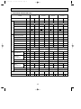
Page 9
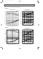
3. CONDENSING PRESSURE AND SUCTION PRESSURE
Data is based on the condition under indoor humidity 50%.
Air flow should be set at HI.
A point on the curve shows the reference point.
<PKH18FL>
COOLING MODE
86
80
75
70 (psi.G) 100
86
80
75
70
90
Suction pressure
Condensing pressure
(psi.G) 350
340
330
320
310
300
290
280
270
260
250
240
230
220
210
200
190
180
170
160
150
80
Indoor DB temperature( F)
70
60
50
40
Indoor DB
temperature( F)
30
30
40
50
60
70
80
90
Outdoor ambient temperature
100
110
DB( F)
20
30
40
50
60
70
80
90
Outdoor ambient temperature
100
Data is based on the condition under outdoor humidity 75%.
A point on the curve shows the reference point.
HEATING MODE
(psi.G) 350
340
330
320
310
300
290
280
270
260
250
F)
240
e(
230
ur
t
75
ra
220
70
pe
m
210
65
te
B
200
D
r
190
oo
180 Ind
170
160
150
20 25 30 35 40 45 50 55 60 65 70
DB( F)
Outdoor ambient temperature
80
F)
Condensing pressure
(psi.G)
75
70
65
50
40
pe
r
DB
te
m
60
In
do
or
Suction pressure
at
ur
e(
70
30
20
10
20 25 30 35 40 45 50 55 60 65 70
DB( F)
Outdoor ambient temperature
9
110
DB( F)
OC276-A-1.qxp
03.11.25 9:04 AM
Page 10
Data is based on the condition under indoor humidity 50%.
Air flow should be set at HI.
A point on the curve shows the reference point.
<PKH24FL>
COOLING MODE
360
(psi.G) 350
340
330
320
310
300
290
280
270
260
250
240
230
220
210
200
190
180
170
160
Suction pressure
Condensing pressure
86
80 (psi.G) 100
75
70
90
Indoor DB
temperature( F)
80
86
80
75
70
Indoor DB temperature( F)
70
60
50
40
30
30
40
50
60
70
80
90
Outdoor ambient temperature
100
20
110
DB( F)
30
40
50
60
70
80
90
Outdoor ambient temperature
100
Data is based on the condition under outdoor humidity 75%.
A point on the curve shows the reference point.
HEATING MODE
(psi.G) 350
340
330
320
310
300
)
290
(F
280
re
u
t
270
ra
75
pe
260
m
70
te
250
B
65
D
240
r
oo
230
d
n
220 I
210
200
190
180
170
160
150
20 25 30 35 40 45 50 55 60 65 70
DB( F)
Outdoor ambient temperature
e(
F)
(psi.G) 80
tu
r
te
m
60
40
do
or
DB
50
In
Suction pressure
75
70
65
pe
ra
Condensing pressure
70
30
20
10
20 25 30 35 40 45 50 55 60 65 70
DB( F)
Outdoor ambient temperature
10
110
DB( F)
OC276-A-1.qxp
03.11.25 9:04 AM
Page 11
Data is based on the condition under indoor humidity 50%.
Air flow should be set at HI.
A point on the curve shows the reference point.
<PKH30FL>
COOLING MODE
(psi.G) 350
340
330
320
310
300
290
280
270
260
250
240
230
220
210
200
190
180
170
160
150
Suction pressure
Condensing pressure
86
80 (psi.G) 110
75
100
70
Indoor DB temperature( F)
86
80
75
70
90
Indoor DB temperature( F)
80
70
60
50
40
30
40
50
60
70
80
90
Outdoor ambient temperature
100
110
DB( F)
30
30
40
50
60
70
80
90
Outdoor ambient temperature
100
Data is based on the condition under outdoor humidity 75%.
A point on the curve shows the reference point.
HEATING MODE
(psi.G) 340
330
320
310
300
290
280
F)
e(
270
r
tu
260
ra
75
pe
250
70
m
te
240
65
B
D
230
r
o
o
220
d
210 In
200
190
180
170
160
150
140
20 25 30 35 40 45 50 55 60 65 70
DB( F)
Outdoor ambient temperature
e(
F
)
(psi.G) 80
at
ur
Condensing pressure
70
m
pe
r
te
do
or
40
DB
50
In
Suction pressure
60
75
70
65
30
20
10
20 25 30 35 40 45 50 55 60 65 70
DB( F)
Outdoor ambient temperature
11
110
DB( F)
OC276-A-1.qxp
03.11.25 9:04 AM
Page 12
Data is based on the condition under indoor humidity 50%.
Air flow should be set at HI.
A point on the curve shows the reference point.
<PKH36FL>
COOLING MODE
86
80
75
70
Condensing pressure
(psi.G)
90
86
80
75
70
80
Suction pressure
(psi.G) 350
340
330
320
310
300
290
280
270
260
250
240
230
220
210
200
190
180
170
160
150
Indoor DB temperature( F)
70
Indoor DB temperature( F)
60
50
40
30
20
30
40
50
60
70
80
90
Outdoor ambient temperature
100
30
110
DB( F)
40
50
60
70
80
90
Outdoor ambient temperature
100
Data is based on the condition under outdoor humidity 75%.
A point on the curve shows the reference point.
HEATING MODE
(psi.G) 390
380
370
360
350
340
330
320
310
)
300
(F
e
r
290
tu
75
ra
280
70
pe
m
270
65
te
B
260
D
r
250
oo
240 Ind
230
220
210
200
190
20 25 30 35 40 45 50 55 60 65 70
DB( F)
Outdoor ambient temperature
(F
)
(psi.G) 80
pe
ra
tu
re
Condensing pressure
70
te
m
or
D
40
B
50
In
do
Suction pressure
60
75
70
65
30
20
10
20 25 30 35 40 45 50 55 60 65 70
DB( F)
Outdoor ambient temperature
12
110
DB( F)
OC276-A-1.qxp
03.11.25 9:04 AM
Page 13
4. STANDARD OPERATION DATA
Models
Heating
Cooling
Heating
Cooling
Heating
Cooling
Heating
Voltage
V
208/230
208/230
208/230
208/230
208/230
208/230
208/230
208/230
Frequency
Hz
Total input
kW
1.79
1.56
2.36
2.37
3.12
3.02
3.44
3.54
Indoor fan current
A
0.5
0.5
0.5
0.5
0.6
0.6
0.6
0.6
Booster heater current
A
Outdoor fan current
A
0.75
0.75
Comp. current
A
7.4/6.9
6.1/5.9
9.3/8.7
9.5/8.7
Condensing pressure
psi.G
255
202
240
243
245
236
243
263
Suction pressure
psi.G
81
61
75
63
80
60
74
60
Discharge temperature
˚F
182
126
158
149
158
159
160
170
Condensing temperature
˚F
118
102
115
115
115
113
115
120
Suction temperature
˚F
66
34
46
35
49
32
45
33
Comp.shell bottom temperature
˚F
171
111
141
126
138
130
142
148
Ref. pipe length
ft
Electrical circuit
Refrigerant circuit
Intake
air temperature
Indoor side
PKH36FL
Cooling
Refrigerant charge
Outdoor side
PKH30FL
Unit
Item
Discharge
air temperature
60
60
60
7.6/8.4
7.6/8.4
60
8.7/9.6
8.7/9.6
0.65+0.65 0.65+0.65 0.75+0.75 0.75+0.75 0.75+0.75 0.75+0.75
12.6/11.8 12.2/11.4 14.3/13.2 14.7/13.7
25
25
25
25
5 lbs 8 oz
9 lbs 15 oz
10 lbs 2 oz
10 lbs 9 oz
DB
˚F
80
70
80
70
80
70
80
70
WB
˚F
67
60
67
60
67
60
67
60
DB
˚F
61
96
58
105
59
103
58
109
WB
˚F
59
68
56
70
58
70
56
71
Fan speed
r.p.m.
1,310
1,310
1,400
1,400
Airflow (High)
CFM
710
710
990
990
Intake
air temperature
DB
˚F
95
47
95
47
95
47
95
47
WB
˚F
75
43
75
43
75
43
75
43
Fan speed upper/lower
r.p.m.
790
750/750
760/760
760/760
Airflow
CFM
1,590
3,170
3,350
3,350
Capacity
SHF
PKH24FL
PKH18FL
Btu/h
18,000
18,600
24,000
0.71
0.82
13
25,000
30,000
0.75
33,000
34,200
0.71
38,000
OC276-A-1.qxp
03.11.25 9:04 AM
Page 14
5. OPERATING RANGE
1) POWER SUPPLY
Min.
198V
1 Phase 60Hz 208/230V
Guaranteed voltage range
208V
Max.
253V
230V
2) OPERATION
Air intake temperature
Indoor
Outdoor
Function
Condition
DB(˚F)
WB(˚F)
DB(˚F)
WB(˚F)
Standard temperature
80
67
95
75
Maximum temperature
95
71
115
—
Minimum temperature
67
57
*0
—
Maximum humidity
80
75
80
75
Standard temperature
70
60
47
43
Maximum temperature
80
67
75
65
Minimum temperature
70
60
17
15
Cooling
Heating
* With wind baffle D.B. 23°F if no wind baffle.
6. OUTLET AIR SPEED AND COVERAGE RANGE
Model
Airflow
(CFM)
Air speed
(ft/sec)
Coverage
range(ft)
PKH18FL
710
16.1
41
PKH24FL
710
16.1
41
PKH30FL
990
17.7
50
PKH36FL
990
17.7
50
The air coverage range is the value up to the position
where the air speed is 0.8ft/sec. when air is blown out
horizontally from the unit at the High notch position.
The coverage range should be used only as a general
guideline since it varies according to the size of the
room and furniture installed inside the room.
7. ADDITIONAL REFRIGERANT CHARGE (R22(oz))
Refrigerant piping length (one way)
Outdoor unit
precharged
(up to 100ft)
25ft
40ft
55ft
70ft
85ft
PKH18FL
5 lbs 8 oz
0
0
0
0
0
0
2
4
PKH24FL
9 lbs 15 oz
0
0
0
0
0
0
2
4
7
9
PKH30FL
10 lbs 2 oz
0
0
0
0
0
0
5
10
16
20
PKH36FL
10 lbs 9 oz
0
0
0
0
0
0
5
10
16
20
Model
100ft 115ft 130ft 150ft 164ft
14
OC276-A-1.qxp
03.11.25 9:04 AM
Page 15
6. NOISE CRITERION CURVES
OCTAVE BAND SOUND PRESSURE LEVEL, dB re 0.0002 MICRO BAR
PKH18FL
PKH24FL
NOTCH SPL(dB)
Hi
48
Lo
41
LINE
3.3ft
90
80
70
NC-70
60
NC-60
50
NC-50
40
NC-40
30
NC-30
20
10
APPROXIMATE
THRESHOLD OF
HEARING FOR
CONTINUOUS
NOISE
63
NC-20
125 250 500 1000 2000 4000 8000
BAND CENTER FREQUENCIES, Hz
NOTCH SPL(dB)
Hi
49
Lo
44
PKH30FL
PKH36FL
OCTAVE BAND SOUND PRESSURE LEVEL, dB re 0.0002 MICRO BAR
Ambient temperature 80˚F
Test conditions are based on JIS Z8731
LINE
90
80
70
NC-70
60
NC-60
50
NC-50
40
NC-40
30
NC-30
20
10
APPROXIMATE
THRESHOLD OF
HEARING FOR
CONTINUOUS
NOISE
63
NC-20
125 250 500 1000 2000 4000 8000
BAND CENTER FREQUENCIES, Hz
15
Unit
Wall
3.3ft
16
32-{15/32
hole for bolt
66-{1/4 hole for
tapping screw
Wall fixture
1-17/32
B
8-27/32
23/32
3-27/32
1-15/32
2-29/32
A
1-3/16
Knock out hole for piping
1-15/32
2-9/16
7-3/32
12-{1/4 Hole for
tapping screw
9-7/16
on left-hand side
12-3/8
42-15/16
9-1/4
Air outlet
Refrigerant pipe. Drain pipe
9-1/4
Right side
Terminal block for control
7-3/4
9-7/16
B
Terminal block for power supply
Gas pipe
4-7/32
4-3/8
Drain hose O.D.1-1/16(or 7/8)
Bolt
19/32
C
Knock out hole for right piping
Refrigerant pipe. Drain pipe
Liquid pipe 3/8F
Gas pipe 5/8F
2-5/32
4-23/32 (Gas pipe)
7-7/32 (Liquid pipe)
Change vane (manual)
Under panel
Removable at left-hand
side piping
Knock out hole for under-piping
44-3/32
21-23/32
Auto vane
Lower side
Drain hose
Liquid pipe
1-25/32
Air intake
55-1/8
Front
1-25/32
9-1/4
Top
43-11/16
9-1/4
1-25/32
21-23/32 Air outlet
9-1/4
3-17/32 Rear piping opening
3-19/32
Range for left rear piping opening
11-1/32
24
on right-hand side
11-7/32
3/4
17-29/32
10x3-19/32=(35-13/16)
35-7/16
Drainage range
23/32 Drainage range
Drain hose for 31/32
left-hand side piping
Knock out hole for
left piping
9-21/32
Unit center
1-15/32
1-17/32
5/32 3-15/16
38-31/32
2-9/16
2-29/32
C
1-3/16
A
13-3/8
13/32
1-3/16
1-5/32
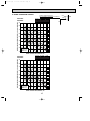
Indoor Unit
PKH18FL
PKH24FL
3-15/16
5/32 1-17/32
Left side
2-3/8
2-15/32
1/2
5
1-3/18 7-1/4
1-3/16
3-5/32
11-1/32
03.11.25 9:04 AM
1-21/32
2-9/32
OC276-A-1.qxp
Page 16
OUTLINES AND DIMENSIONS
Unit : inch
1-15/32
41- 15/32 hole
for bolt
11-5/8
1-15/32
9-7/16
50
7-3/32
Range for left rear piping hole
A
5-/15/16 or less
1-3/16
or more
Rear piping hole
11-1/32
12-3/8
29-17/32
11-7/32
3/4
9-21/32
Drainage range on
right-hand side
Drain hose for
left-hand side piping
31/32
Knock out hole
for left piping
Left side
23-7/16
13x3-19/32=(7-3/16)
35-7/16
3-19/32
Unit center
2-9/16
2-9/16
Range for left
rear piping hole
8-27/32
23/32 23/32
Wall fixture
Unit out line
Drainage range on
Left hand side
3-27/32
B
C
1-3/16
2-29/32
10 or more
Knock out hole for wiring
1-17/32
2-29/32
A
1-3/16
84-{1/4 hole
for tapping
screw
3-15/16
5/32 1-17/32
2 or more
1-15/32
Air
outlet
5/32 3-15/16
for tapping screw
12- 1/4 hole
7-17/32
9-1/4
1-25/32
9-1/4
1-25/32
1
7-7/32
Knock out hole for under-piping
Refrigerant pipe .Drain pipe
Auto vanes
Under panel (Removable at
left-hand piping)
louvers(manual)
Lower side
55-1/8
27-5/16 Air outlet
43-11/16 (Drain hose)
Drain hose
Terminal block for power supply
Terminal block for control
66-5/32
53-15/16 Air Intake
Front
9-1/4
1-25/32
9-1/4
1-25/32
27-5/16 Air outlet
9-1/4
Top
2-15/32
2
Knock out hole
for right piping
1/2
Air
intake
10 or more
1-17/32
Front
13-3/8
13/32
1-3/16
1-3/16
17
7-1/4
1-3/16
3-5/32
1-5/32
11-1/32
9-7/16
B
2-5/32(Gas pipe)
4-23/32(Liquid pipe)
19/32
or less
C
4-3/8
Liquid pipe
Gas pipe
1/2F
3/4F
3-1/2~
4
>
< 1 Sleeves are available
on the market.
3-1/2
Sleeve >< 1 Through hole
1
2
Drain hose O.D.1-1/16(or 7/8)
Bolt
4-1/32
9-1/4
Right side
PKH30FL
PKH36FL
2-3/8
2-9/32
03.11.25 9:04 AM
1-21/32
7-3/4
OC276-A-1.qxp
Page 17
Unit : inch
OC276-A-1.qxp
03.11.25 9:04 AM
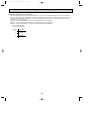
Page 18
Remote controller
Unit : inch
WIRELESS REMOTE CONTROLLER
2-9/32
COOL
DRY
AUTO
FAN
HEAT
CHECK TEST
MODEL RUN
SELECT
FAN
3/4
˚F
˚C
STOP AMPM
SWING
START AMPM
NOT AVAILABLE
TEMP
6-3/8
ON/OFF
6
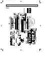
REFRIGERANT SYSTEM DIAGRAM
PKH18FL
PKH24FL
Refrigerant pipe
(option)
{5/8"
(with heat insulator)
Flared connection
Strainer
Pipe temperature
thermistor / Liquid
(RT2)
Distributor
Restrictor
valve
Refrigerant flow
Refrigerant pipe
(option)
{3/8"
(with heat insulator)
Flared connection
Capillary tube
PKH18FL : ({0.126x{0.071x19.7)
PKH24FL : ({0.157x{0.079x19.7) w
PKH30FL
PKH36FL
Strainer
Pipe temperature
thermistor / Liquid
(RT2)
Distributor
Restrictor
valve
Refrigerant pipe
(option)
{3/4"
(with heat insulator)
Flared connection
Refrigerant pipe
(option)
{1/2"
(with heat insulator)
Flared connection
Capillary tube
PKH30FL : ({0.157x{0.079x23.6)
PKH36FL : ({0.157x{0.079x15.7)
18
HEATING
COOLING
w An error in this diagram has been
modified. The size of capillary tube
{0.157x{0.07x19.7, was wrong.
OC276-A-1.qxp
03.11.25 9:04 AM
7
Page 19
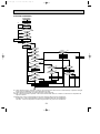
WIRING DIAGRAM
MODELS PKH18FL, PKH24FL, PKH30FL, PKH36FL WIRING DIAGRAM
H
FS2 FS1
1
2
RED 5
BLU 6
MV
TB2
RED
BLU
GRN/YLW
3
2
1
123
P.B
L1
L2
GR
W.B
BZ
6
9
BLK
WHT
RED
BLU
BLK
WHT
RED
WHT
BLK
POWER
1 3 CNDK 1 3
135
(WHT)
F2
CNB
POWER
CND 1 2 VANE
(RED) CN2D CN6V
F1
(WHT) (WHT)
SW3
ON
OFF
12
SW8
SW1
SW5
ON
OFF
12 345
SW6
ON
OFF
MODELS
SW7
18FL
24FL
ON
OFF
ON
OFF
12 3
30FL
ON
OFF
12 3
1 234
36FL
P.B
I.B
C
MF
CN2L
CN51
FC
SW1
SW2
SW3
SW5
SW6
SW7
SW8
SW9
X4
F1,F2
ZNR
LED1
LED2
3
2
1
12 123 12 12
PIPE
CN21
(WHT)
BRN 3
ORN 2
YLW 1
LED1
SW1
SW2
RU
TB4
TRANSMISSION WIRES DC12V
3
2
1
TB3
OUTDOOR UNIT
RT2 RT1
26H
5 GRY
8 88H 7 6 GRY
12 3
[LEGEND]
SYMBOL
OUT
INTAKE
CN20 LOSSNAY DOOR
CN2L CN30
(RED)
(BLU)
123
ON
OFF
12 3
2
1
HEATER
CN24
(YLW)
DRAIN
CN31
(WHT)
4
3
2
1
REMOCON
CN22
(BLU)
SW7
ON
OFF
1 2345 6 1 234 5678 910
123 456 12 34
CENTRALLY REMOCON
POWER
CONTROL
CN40
CN51
(WHT)
SW9
YLW
BWN
SW2
ON
OFF
9
LED1 LED2 WIRELESS
CN90
ZNR
(WHT)
X4
LED2
W.R
REMOTE
CONTROLLER
X4
FC
POWER SUPPLY
~(1PHASE)
AC208/230V 60Hz
GROUND
2
1
C
FAN
(WHT)
3 RED
4 BLU
(DC13.1V)
(AC208/230V)
CN2S (WHT)
CNSK(RED)
TRANS
MF
I.B
88H
NAME
SYMBOL
INDOOR POWER BOARD
INDOOR CONTROLLER BOARD
CONNECTOR(LOSSNAY)
CONNECTOR(CENTRALLY CONTROL)
FAN PHASE CONTROL
SWITCH(FUNCTION SELECTOR)
SWITCH(ADDRESS SELECTOR)
SWITCH(EMERGENCY OPERATION)
SWITCH(MODEL SELECTOR)
SWITCH(TWIN/TRIPLE SELECTOR)
SWITCH(MODEL SELECTOR)
SWITCH(OPTION)
SWITCH(MODEL SELECTOR)
RELAY(FAN MOTOR)
FUSE(6A/250V)
VARISTOR
LED(DC12V POWER)
LED(DC5V POWER)
CAPACITOR(FAN MOTOR)
FAN MOTOR
NAME
VANE MOTOR
MV
TB2~TB6 TERMINAL BLOCK
RT1
ROOM TEMPERATURE THERMISTOR
(32˚F /15kΩ, 77˚F /5.4kΩ DETECT)
RT2
PIPE TEMPERATURE THERMISTOR/LIQUID
(32˚F /15kΩ, 77˚F /5.4kΩ DETECT)
WIRELESS REMOTE CONTROLLER
W.R
W.B
WIRELESS REMOTE CONTROLLER BOARD
RECEIVING UNIT
RU
BZ
BUZZER
LED1 LED(RUN INDICATOR)
LED2 LED(HOT ADJUST)
SW1 SWITCH(HEATER ON/OFF)
SW2 SWITCH(COOLING ON/OFF)
HEATER
FS1,2 THERMAL FUSE
243˚F ,10A(18,24FL)/16A(30,36FL)
H
HEATER
26H HEATER THERMAL SWITCH
88H HEATER CONTACTOR
NOTES:
1.Since the indoor fan motor(MF)is connected with 230V power,if 208V power is used,change the dip switch(SW8)on
the indoor controller board as shown in fig:*1.
SW8
SW8
fig:*1
ON
ON
Indoor fan motor(MF)for 208V.
OFF
OFF
123456
123456
2.Since the outdoor side electric wiring may change be sure to check the outdoor unit electric wiring for servicing.
3.Indoor and outdoor connecting wires are made with polarities, make wiring matching terminal numbers.
4.Symbols used in wiring diagram above are,
:Connector, :Terminal block.
5.Emergency operation
If remote controller or microcomputer fails but there is no other trouble emergency operation is possible by setting
dip switch(SW3<I.B>) on the indoor controller board.
[Check items]
(1) Make sure that no other trouble exist in the outdoor unit.Trouble with the outdoor unit prevents emergency operation.
(2) Make sure that there is no trouble with the indoor fan.
Emergency operation will be continuous run with the power ON/OFF(ON/OFF with the remote controller is not possible).
[Emergency operation procedure]
(1) Set the dip switch(SW3<I.B>)on the indoor controller board to 1 on and 2 off for cooling and 1 • 2 on for heating.
(2) Turn on outdoor unit side circuit breaker,then indoor unit side circuit breaker.
(3) During emergency operation indoor fan runs at high speed but auto-vane does not work.
(4) Thermostat will not function.Cold air blows out for defrosting during heating thus do not operate defrosting for a long time.
(5) Emergency cooling should be limited to 10 hours maximum
(the indoor unit heat exchanger may freeze).
(6) After every emergency operation,set all dip switches(SW3<I.B>) to OFF.
(7) Movement of the vanes does not work in emergency operation,therefore you have to slowly set them manually to the
appropriate position.
RG79J693H02
19
The drawing has been revised as some errors in
WIRING DIAGRAM have been modified.
The former drawing number is RG79J693H01.
OC276-A-1.qxp
8
03.11.25 9:04 AM
Page 20
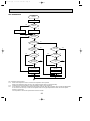
OPERATION FLOW-CHART
MAIN OPERATION
START
Power circuit
breaker
1
NO
YES
YES
Check SW
ON twice
NO
Operation SW
ON
w 1
YES
NO
“OFF” timer
YES
NO
NO
Set time
complete
“ON” timer
YES
YES
Set time
complete
NO
YES
w 2
NO
Trouble
NO
YES
STOP
Trouble STOP
PROTECTION DEVICE
SELF HOLD RELEASE
PROTECTION DEVICE
SELF HOLD
Remote controller
operation display
Operating mode
(COOL)
NO
Operating mode
(DRY)
w 3
Remote controller
trouble display
Remote controller
indicator lamp OFF
NO
Operating mode
(HEAT)
Indoor side
NO
w 4
w 6
Fan STOP
Operating mode
(FAN)
NO
Auxiliary heater OFF
YES
COOL operation
YES
DRY operation
YES
HEAT operation
YES
w 7
FAN operation
Auto COOL/HEAT
operation
Outdoor side
w 5
Compressor OFF
Fan STOP
Four-way valve OFF
w1 In addition, the centralised control and remote control can be operated.
w2 The modes which indicate the sources of trouble are listed below.
● E0-Signal transmitting/receiving error
● P1-Room temperature thermistor malfunction
● P2-Indoor coil thermistor malfunction
● P4-Drain sensor malfunction
● P5-Drain overflow
● P6-Coil frost/overheat protection
● P7-System error
● P8-Outdoor unit trouble
w3 The CHECK switch will show if an error has occurred in the past.
w4 Fan runs on low speed for 1 minute in order to remove overheat air.
w5 The 3-minute (6 minutes … heating mode) time-delay functions after compressor stops.
w6 FAN or AUTO mode is selected by the indoor dip switch setting.
w7 In FAN mode, fan speed and vane operation depend on the remote controller setting. (Compressor is OFF.)
20
OC276-A-1.qxp
03.11.25 9:04 AM
Page 21
COOLING OPERATION
COOL operation
Four-way valve/OFF
NO
w8
Initial
COOLING
YES
Vane initial
setting
Vane
55 deg downward angle
70 deg downward angle
NO
YES
Fan speed
LOW
NO
YES
NO
Vane setting notch
Downward discharge
1 hour
YES
Vane horizontal
airflow
w9
YES
Compressor
thermostat ON
NO
Allowance
cancel
NO YES
3-minute
time delay
YES
NO
6-minute
time delay
NO
3-minute
compressor operation
Allowance
period
NO
6 minute
time delay
NO
w 10
YES
NO
Cooling area
YES
10-minute
compressor operation
NO
Indoor coil
temperature is 50˚F
or higher
YES
YES
Allowance cancel
Coil frost
prevention
NO
NO
Defrosting
protection detection
temperature 30˚F
or lower
YES
YES
16-minute
compressor operation
YES
Indoor pipe
temperature is 34˚F
or lower
NO
Compressor ON
Coil frost protection
Allowance set
YES
Coil frost
protection
NO
w 11
NO
YES
NO
NO
1 min continue
YES
FAN speed
LOW
FAN speed
LOW 5 min elapse
YES
NO
6-minute
time delay
3-minute
time delay
Outdoor unit
trouble
YES
Coil frost
prevention
Coil frost
prevention release
Compressor OFF
1
w8 When operation stops or changes to cooling or dry mode, the auto vane turns to a horizontal angle. If operation changes
during auto vane SWING, the auto vane will continue to swing.
w9 When operating TEST RUN, the thermostat will be continuously ON.
w10 After 3 minute compressor operation, if the indoor coil thermistor reads 5°F or below for 3 minutes, the compressor will
stop for 6 minutes.
w11Heating area : Indoor coil temperature is more than 9 degrees above the room temperature.
Cooling area : Indoor coil temperature is more than 9 degrees below the room temperature.
FAN area : Indoor coil temperature is within 9 degrees either way of the room temperature.
21
OC276-A-1.qxp
03.11.25 9:04 AM
Page 22
DRY OPERATION
DRY
operation
Four-way valve / OFF
NO
Initial dry
operation
w8
YES
Vane
setting notch
Vane initial setting
YES
w12
Room temperature is
64°F or lower
NO
NO
During
compressor ON
YES
3-minute
compressor
operation
NO
NO
YES
NO
YES
3-minute
time delay
w9
Compressor &
thermostat ON
YES
Compressor &
thermostat
ON
w9
NO
YES
NO
Compressor ON
time completes
10-minute
compressor
OFF
NO
YES
YES
w13
10-minute compressor
OFF timer start
Compressor ON
time set
Compressor OFF
Compressor ON
w14
w14
Fan STOP
Fan speed LOW
1
w8—9 Refer to page OC276-21.
w12
When room temperature is 64°F or below, the compressor cannot operate.
When room temperature rises over 64°F the compressor starts after a 3-minute time delay.
w13
Compressor ON time is decided by room temperature. Refer to page OC276-30.
w14
In dry operation, compressor ON makes the fan speed LOW. Also, when the compressor OFF and the pipe temperature
is 79°F or less, the fan stops, or when the compressor OFF and the pipe temperature is below 43°F the fan speed
changes to LOW mode.
It is not possible to set the fan speed with the remote controller
22
OC276-A-1.qxp
03.11.25 9:04 AM
Page 23
HEATING OPERATION
Heat operation
NO
Vane setting
notch
initial
HEATING
YES
Vane initial
setting
NO
A
w 11
YES
Heating area
w 15
NO
Defrost
NO
30 min. elapse
NO
Four-way
valve ON
Defrost release
2
YES
Outdoor unit
trouble
YES
defrosting
3-minute
NO
Auxiliary heater
OFF
YES
Indoor coil
NO
thermistor is 140°F
or higher
YES
FAN speed NO
Low notch
YES
FAN setting
Airflow 10% up
notch
1
Hot adjust YES
in process
NO
YES
Compressor ON
w9
B
NO
Compressor YES
thermostat ON
NO
Allowance cancel
YES
3 min.restart
prevention
NO
NO
YES
6 min. restart
prevention
NO Indoor piping
5°F or lower
YES
2
Outdoor unit
trouble
FAN SPEED
Very low airflow
Compressor OFF
NO
10-minute
compressor
operation
YES
Allowance cancel
B
HOT adjust NO
5 min. elapse
YES
Indoor piping YES
131°F or lower
NO
w 11
Heating YES
area
NO
FAN STOP
YES Indoor piping
95°F or higher
NO
NO
Auxiliary
heater ON
YES
NO Indoor piping
140°F or higher
A
NO Auxiliary heater
thermostat ON
YES
Auxiliary heater
ON
w 11
YES
Fan area YES
20 min.elaspe
Auxiliary heater
OFF
NO
YES
w 10
Overheat remote
Hot adjust start
Fan area
Outdoor unit
START
Heating area
trouble
NO
FAN SPEED
w
11
very low
NO
Fan area
NO Indoor Coil. temp.
Cooling area
150°F or higher
Compressor ON
YES
YES
Defrost operation
START
Allowance NO
period
Four-way valve
6-minute restart
YES
OFF
prevention
Overload protect
Allowance set
1
AUTOMATIC COOLING/HEATING OPERATION
Compressor OFF
Auto COOL/HEAT
operation
w 16
NO
Initial mode
w 17
1
YES
T1 >
= To
NO
YES
COOL mode
COOL mode
HEAT mode
NO
YES
NO
NO T1 [ (To - 4)
YES
After 15min. YES
T1 ] (To + 4)
YES
After 15min. YES
T1 [ (To-4)
NO
NO
COOL operation
T1 ] (To + 4)
HEAT operation
HEAT operation
Cool mode
set
1
1
w15 ( i ) Until Low airflow is set while in hot adjustment
( ii )While defrosting (FAN STOP)
(iii)When thermostat is OFF
In the case of( i ), (ii) and (iii) above, airflow is horizontal regardless the VANE setting.
w16 When AUTO operation is started, COOL or HEAT mode is selected automatically.
w17 T1 : Room temperature.
To : Set temperature
23
FAN SPEED
Low
FAN SPEED NO
Low 2 min.
elapse
YES
FAN SPEED
setting notch
Hot adjust
release
OC276-A-1.qxp
9
03.11.25 9:04 AM
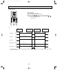
Page 24
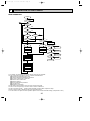
MICROPROCESSOR CONTROL
1.OUTLINE OF MICROPROCESSOR CONTROL
INPUT to remote controller
● OFF-ON switching.
● COOL/DRY-AUTO-HEAT selector switching.
● Thermostat setting.
● TIMER mode selector-switching and Timer
setting.
● HIGH-LOW fan speed switching.
● AUTO Vane selector (AIR DISCHARGE)
switching.
● TEST RUN switching.
● CHECK mode switching.
(Self diagnostic trouble shooting)
Remote controller board
● Processes and transmits
orders.
OUTPUT to remote controller
● Indication LCD lights.
COOL
DRY
AUTO
FAN
HEAT
CHECK TEST
MODEL RUN
SELECT
FAN
˚F
˚C
STOP AMPM
SWING
START AMPM
NOT AVAILABLE
ON/OFF
TEMP
Indoor
unit
Indoor controller board
INPUT from indoor unit
● Room temperature thermistor (RT1)
● Pipe temperature thermistor (RT2)
OUTPUT to indoor unit
● Receives orders from remote controller and temperature data from indoor unit.
● Processes orders and data.
● Controls indoor and outdoor operation.
● Self diagnostic function.
w System control operation.
w Emergency operation.
w Set by dip switch on indoor controller board.
Polar three-wire cable
● Compressor protection
device working
● Defrosting
START-STOP
● Fan speed control.
● Crankcase heater control
ON-OFF.
● Self diagnostic function
Outdoor unit
12VDC
Independent Control of
Outdoor Unit
1
2
3
24
OUTPUT to outdoor unit
1 2 3
● Auto vane’s angle setting.
● Booster heater ON-OFF Control.
● Emergency stop.
● Compressor and
outdoor fan : ONOFF
● Operation mode
change :COOLHEAT.
OC276-A-1.qxp
03.11.25 9:05 AM
Page 25
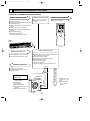
2. INDOOR UNIT CONTROL
2-1 COOL operation
COOL
<How to operate>
1 Press POWER ON/OFF button.
2 Press the MODE button to display COOL.
3 Press the TEMP(
or
) button to set the desired temperature.
NOTE: Set temperature changes 2°F when the TEMP(
or
)
button is pressed one time.
Cooling 65 to 87°F.
˚F
FAN
AM
ON/OFF
MODE
TEMP
FAN
AUTO STOP
VANE
AUTO START
CHECK LOUVER
h
TEST RUN
SET
min
RESET
CLOCK
<COOL operation time chart>
Operation starts by
POWER button
ON.
Room temperature
becomes equal to
set temperature.
Room temperature
rises above set
temperature.
Operation stops by
POWER button
OFF.
ON
Thermostat
OFF
ON
Indoor fan
LOW or HIGH
LOW or HIGH
OFF
ON
Auto vane
OFF
Booster heater
OFF
ON
OFF
ON
Compressor
OFF
Minimum 3 minutes
w1
w1 Even if the room temperature rise above the set temperature during this period, the compressor will not start until this period has ended.
25
OC276-A-1.qxp
03.11.25 9:05 AM
Page 26
(1) Compressor control
1 3-minute time delay
To prevent overload, the compressor will not start within 3 minutes after stop.
2 The compressor runs when room temperature is higher than set temperature.
The compressor stops when room temperature is equal to or lower than the set temperature.
The compressor maintains the previous state when the room temperature minus the set temperature is 0 degrees or more,
or lower than 2 degrees.
3 The compressor stops in check mode or during protective functions.
4 Coil frost prevention
To prevent indoor coil frost, the compressor will stop when the indoor coil thermistor (RT2) reads 34°F or below after the
compressor has been continuously operated for at least 16 minutes or more. When the indoor coil temperature rises to
50°F or above, the compressor will start in a 3-minute(w2) time delay.
w2 When the indoor coil temperature is 30°F or less, the compressor starts in 6 minutes.
NOTE : By turning OFF the dip switch SW1-3 on indoor controller board, the start temperature of coil frost prevention changes
from 34°F to 36°F.
5 Coil frost protection
When indoor coil temperature becomes 5°F or below,coil frost protection will proceed as follows.
<Start condition>
After the compressor has been continuously operated for 3 minutes or more,and the indoor coil temperature has been 5°F
or below for 3 minutes,the coil frost protection will start.
<Coil frost protection>
Compressor stops for 6 minutes,and then restarts.
lf the start condition is satisfied again during the first 10 minutes of compressor operation,both the indoor and outdoor units
stop,displaying a check code of“P6”on the remote controller.
<Termination conditions>
Coil frost protection is released when the start condition is not satisfied again during the allowance, or when the COOL
mode stops or changes to another mode.
(2) Indoor fan control
Indoor fan speed depends on the remote controller setting.
However, if an outdoor unit abnormality is detected, the indoor fan speed will be low, regardless of the remote controller
setting.
When the outdoor unit abnormality detection is released and the fan speed returns to the set speed, the quiet cycle control
will work.
(a) Normal control
( i ) Fan speed depends on the remote controller setting regardless of the thermostat on/off.
(ii) Fan speed will remain on low if an abnormality in outdoor unit is detected. (5 minutes)
5 minutes
SET
5 minutes
1 Start-up of outdoor unit abnormality detection.
2 Release of outdoor unit abnormality detection.
3 Unit stop due to outdoor unit abnormality
with P8 indication.
SET
low
low
OFF
NOTE 1 : Fan stops immediately if the unit stops or the check mode is started.
26
OC276-A-1.qxp
03.11.25 9:05 AM
Page 27
(3) Auto vane control
Auto vane position is set to 10 degrees airflow at the start-up of COOL operation. It can then be changed by the remote
controller.
(a) Vane position set mode & swing mode.
( i ) Every time AIR DISCHARGE button is pressed, setting will be changed .
( ii ) Airflow direction can be changed with AIR DISCHARGE button.
1 Fan speed : LOW
10°
60°
70°
SWING
60°
70°
SWING
2 Fan speed : HIGH
10°
30°
<AUTO RETURN>
When discharge 60° or 70° continues for 1 hour with the fan speed at LOW, the discharge direction turns to the horizontal
discharge automatically.
After that, 60° or 70° is available by setting with the remote controller, and it continues for 1 hour.
If the discharge direction changes from 60° or 70°, the direction returns to the horizontal discharge when 1 hour has
passed since the discharge 60° started.
If the discharge direction changes from 60° (or 70°) to the horizontal discharge, the 1-hour timer to return the horizontal
discharge is cancelled.
<Remote controller display>
1 10°
2 30° downward
3 60° downward
4 70° downward
5 SWING
Changes by pressing the AIR DISCHARGE button.
27
OC276-A-1.qxp
03.11.25 9:05 AM
Page 28
(4) Detecting abnormalities in the outdoor unit
After the compressor has been continuously operated for 3 minutes, if the difference between the indoor coil temperature
and room temperature is out of RANGE C for 1 minute, the indoor fan speed will turn to LOW. Five minutes later, if the difference is still out of RANGE C,the outdoor unit is functioning abnormally. Thus, the compressor stops and check code
“P8” appears on remote controller.
RANGE A : Indoor coil temperature is more than 9 degrees above room temperature.
RANGE B : Indoor coil temperature is within 9 degrees either way of room temperature.
RANGE C : Indoor coil temperature is more than 9 degrees below room temperature.
Indoor coil temperature
minus room temperature
(degree)
+9
0
-9
RANGE A
RANGE B
RANGE C
28
OC276-A-1.qxp
03.11.25 9:05 AM
Page 29
2-2 DRY operation
<How to operate>
1 Press POWER ON/OFF button.
2 Press the MODE button to display “DRY”
3 Press the TEMP(
or
) button to set the desired temperature.
NOTE: The set temperature changes 2°F when the TEMP(
or
)
button is pressed one time.
Dry 65 to 87°F
˚F
DRY
FAN
AM
ON/OFF
MODE
TEMP
FAN
AUTO STOP
VANE
AUTO START
CHECK LOUVER
TEST RUN
SET
h
min
RESET
CLOCK
<DRY operation time chart>
Operation starts by
POWER button
ON.
Room temperature
becomes equal to
set temperature.
Room temperature
rises above set
temperature.
Operation stops by
POWER button
OFF.
ON
Thermostat
OFF
DRY MODE
DRY MODE
ON
Indoor fan
OFF
Auto vane
OFF
ON
ON
Booster heater OFF
OFF
ON
Compressor
OFF
Minimum 3 minutes w1
w1 Even if the room temperature rises above the set temperature during this period, the compressor will not start until this
period has ended.
29
OC276-A-1.qxp
03.11.25 9:05 AM
Page 30
1) Compressor control
1 3-minute time delay
To prevent overload, the compressor will not start within 3 minutes after stop.
2 The compressor runs when room temperature is higher than set temperature.
The compressor stops when room temperature is equal to or lower than the set temperature.
The compressor maintains the previous state when the room temperature minus the set temperature is 0°F or more, or
lower than 2°F.
3 The compressor stops in check mode or during protective functions.
4 The compressor will not start when the room temperature is 64°F or below.
The compressor starts intermittent operation when the power is turned ON with room temperature above 64°F. The compressor ON/OFF time depends on the thermostat ON/OFF and the following room temperatures.After 3-minute compressor
operation,
● If the room temperature thermistor reads above 82°F with thermostat ON, the compressor will operate for 6 more minutes
and then stop for 3 minutes.
● If the room temperature thermistor reads 79°F to 82°F with thermostat ON, the compressor will operate for 4 more minutes and then stop for 3 minutes.
● If the room temperature thermistor reads 75°F to 79°F with thermostat ON, the compressor will operate for 2 more minutes and then stop for 3 minutes.
● If the room temperature thermistor reads below 75°F with thermostat ON, the compressor will stop for 3 minutes.
● If the thermostat is OFF regardless of room temperature, the compressor will stop for 10 minutes.
5Coil frost protection
Coil frost protection in DRY operation is the same as in COOL operation.
6Coil frost prevention
Coil frost prevention does not operate in DRY operation.
(2) Indoor fan control
The indoor fan runs on LOW speed during compressor operation. The fan speed cannot be changed with the remote controller. Also, the fan runs on LOW speed when the pipe temperature is 43°F or more, or the compressor is OFF and the
pipe temperature is below 43°F.
(a)During compressor OFF
● When the indoor coil temperature is 43°F or above, the indoor fan will stop.
● When the indoor coil temperature is below 43°F, the indoor fan will run on LOW speed.
(b)During compressor ON
● The indoor fan runs on LOW speed.
<Dry mode>
The fan notch is controlled by the indoor coil temperature every 30 seconds.
Fan control in DRY operation.
Pipe temp.
Fan
43°F or more
STOP
Below 43°F
LOW
All
LOW
Compressor OFF
Compressor ON
(3) Auto vane control
Same as in COOL operation
(4) Detecting abnormalities in the outdoor unit
An abnormality in the outdoor unit can not be detected in DRY operation.
30
OC276-A-2.qxp
03.11.25 9:06 AM
Page 31
2-3 HEAT operation
FAN
AUTO STOP
<How to operate>
1 Press POWER ON/OFF button.
2 Press the MODE button to display “HEAT”
3 Press the TEMP(
or
) button to set the desired temperature.
NOTE: The set temperature changes 2°F when the TEMP(
or
).
button is pressed one time.
Heating 63 to 83°F.
<Display in HEAT operation>
VANE
AUTO START
[DEFROST]
˚F
FAN
AM
HEAT
ON/OFF
MODE
TEMP
CHECK LOUVER
TEST RUN
SET
The [DEFROST] symbol is only displayed during the defrost operation.
h
[STANDBY]
min
RESET
The [STANDBY] symbol is only displayed from the time the heating
operation starts until the heated air begins to blow.
CLOCK
<HEAT operation time chart>
Operation starts by
POWER button
ON.
Thermostat
Room temperature
becomes equal to
set temperature.
OFF
LOW w1
LOW w1
Booster heater
Compressor
LOW or HIGH
LOW or HIGH
w1 Changeable LOW or HIGH
by indoor dip switch SW1- 6 .
OFF
ON
Auto vane
Operation stops by
POWER button
OFF.
ON
ON
Indoor fan
Room temperature
falls below set temperature.
Horizontal
Depends on remote
controller setting
Horizontal
Depends on remote
controller setting
OFF
ON
OFF
Hot adjustment
Hot adjustment
OFF during thermostat OFF
hot adjustment
defrosting
ON
OFF
Minimum 3 minutes w2
Power ON lamp
STAND BY lamp
ON
OFF
ON
From POWER ON until
warm begins to blow
OFF
w2 Even if the room temperature falls below the set temperature during this period, the compressor will not start until this period has ended.
31
OC276-A-2.qxp
03.11.25 9:06 AM
Page 32
(1) Compressor control
13-minute time delay
To prevent overload, the compressor will not start within 3 minutes after stop.
2The compressor runs when the room temperature is lower than the set temperature.
The compressor stops when the room temperature is equal to or higher than the set temperature.
3The compressor stops in check mode or during protective functions.
4Overheat protection
<Start condition>
When the indoor coil thermistor reads 158°F or above, the overheat protection will start.
<Overheat protection>
The compressor stops for 6 minutes, and then restarts.
If the start condition is satisfied again within 10 minutes of compressor operation, both the indoor and outdoor units stop,
displaying a check code of “P6” on the remote controller.
<Termination conditions>
Overheat protection is terminated when the start condition is not satisfied again during the allowance (10-minute compressor operation), when operation mode changes to other mode, or when thermostat turns OFF.
(2) Indoor fan control
(a) Normal control
( i )The indoor fan runs on LOW speed during the thermostat OFF.
LOW speed can be changed to HIGH speed by setting the dip switch SW1-6.
If the indoor coil temperature becomes more than 5 degrees below the room temperature during the thermostat
OFF, the indoor fan will stop. After, when the indoor coil temperature becomes within 5 degrees of room temperature, the indoor fan will run on LOW speed.
( ii )Hot adjustment
Hot adjustment is a warm-up for HEAT operation
<Start conditions>
The hot adjustment works under any of the following conditions.
● HEAT operation starts.
● Defrosting ends.
● Thermostat turns ON.
[Hot adjustment]
Initially, the indoor fan runs on LOW speed. When 5 minutes have passed or the indoor coil temperature exceeds
95°F, the fan speed will not be changed. 2 minutes later, the hot adjustment ends. Then, the fan speed depends on
the remote controller setting.
(iii)The indoor fan stops when the indoor coil temperature is within 9 degrees either way of room temperature.
(iv)To eliminate the remaining heat, the indoor fan runs for the first 1 minute after the booster heater is turned OFF.
(3) Auto vane control
Auto vane position is set to 70 degrees airflow at the start-up of HEAT operation.
(a) Vane position set mode & swing mode.
( i ) Every time AIR DISCHARGE button is pressed, setting will be changed .
( ii ) Airflow direction can be changed with AIR DISCHARGE button.
10°
30°
60°
70°
SWING
NOTE : In the following cases, the discharge direction is 30° regardless of the remote controller setting.
1 During the hot adjustment with fan speed at LOW
2 During defrosting with indoor fan OFF
3 During thermostat OFF
(4) Booster heater control
When the room temperature is 6 degrees below the set temperature, the booster heater will turn ON.
When the room temperature is equal to the set temperature, booster heater will turn OFF.
During the hot adjustment, the booster heater will not work.
<Overheat prevention>
When the indoor coil thermistor rises to 140°F or above, the booster heater cannot work.
When the indoor coil thermistor falls to 131°F or below, the booster heater can work.
32
OC276-A-2.qxp
03.11.25 9:06 AM
Page 33
(5) Detecting abnormalities in the outdoor unit
When the outdoor unit is determined to be abnormal by the following causes, the compressor will stop and the check code
“ P8 ” will appear on the remote controller display.
( i ) During compressor ON while hot adjustment is set.
1 If the difference between the indoor coil temperature and room temperature is in the RANGE B, the indoor fan will
stop.
2 Within 20 minutes after entering RANGE B (except for the first 10 seconds),
a) If the temperature difference enters RANGE A, the hot adjustment starts,
b) If the temperature difference is still in RANGE B, the outdoor unit is deemed abnormal.
c) If the temperature difference enters RANGE C, defrosting starts.
3 Within 20 minutes after entering RANGE C, if the temperature difference does not return to RANGE B,the outdoor
unit is deemed abnormal.
4 If the temperature difference returns to RANGE B, the next 20 minutes is an allowance period. If the difference enter
RANGE A during the allowance, defrosting ends and the hot adjustment starts. If the difference does not enter
RANGE A during the allowance, the outdoor unit is deemed abnormal.
( ii ) During compressor ON in defrosting
After 30 minutes of defrosting in hot adjustment, if the temperature difference is still in RANGE C, the outdoor unit is
determined to be abnormal.
When RANGE B does not change to RANGE A after 20 minutes have passed since RANGE C had outdoor unit is
determined to be abnormal.
( iii ) During compressor OFF
Not detecting abnormalities.
(6) Indoor coil temperature abnormality detection
An abnormality can be detected during compressor ON, except for the following.
●For the first 30 minutes after the temperature difference between the indoor coil temperature and room temperature
enters the RANGE C.
●When the temperature difference enters the RANGE C until it moves to the RANGE B.
(7) Defrosting operation
After the outdoor unit starts the defrosting operation, when the temperature difference between the indoor coil temperature
and room temperature gets out of RANGE A and into RANGE B, the indoor unit starts the defrosting mode. After the outdoor unit stops the defrosting operation, when the temperature difference returns to the RANGE A, the indoor unit stops
the defrosting mode. While the indoor unit is in the defrosting mode, the indoor fan and the booster heater stop.
w1 RANGE A : Indoor coil temperature is more than 9 degrees above room temperature.
RANGE B : Indoor coil temperature is within 9 degrees either way of room temperature.
RANGE C : Indoor coil temperature is more than 9 degrees below room temperature
Indoor coil temperature
minus room temperature
(degree)
+9
RANGE A
0
RANGE B
-9
RANGE C
33
OC276-A-2.qxp
03.11.25 9:06 AM
Page 34
2-4 AUTO operation (Automatic COOL/HEAT change over operation)
<How to operate>
1 Press POWER ON/OFF button.
2 Press the MODE button to display “AUTO”
3 Press the TEMP(
or
) button to set the desired temperature.
NOTE: The set temperature changes 2°F when the TEMP(
or
)
button is pressed one time.
Automatic 65 to 83°F.
●“AUTOMATIC” works to change by itself the operation
mode either to cooling or heating according to the room
temperature.
˚F
AUTO
FAN
AM
ON/OFF
TEMP
MODE
FAN
AUTO STOP
VANE
AUTO START
CHECK LOUVER
h
TEST RUN
SET
min
RESET
CLOCK
(1) Initial mode
1 When AUTO operation starts after unit OFF.
● If the room temperature is higher than the set temperature, operation starts in COOL mode.
● If the room temperature is equal to or lower than the set temperature, operation starts HEAT mode.
2 When AUTO operation starts after COOL or HEAT operation, the previous mode continues.
(2 ) Mode change
1 HEAT mode changes to COOL mode when 15 minutes have passed since the room temperature became 4 degrees
above the set temperature.
2 COOL mode changes to HEAT mode when 15 minutes have passed since the room temperature became 4 degrees
below the set temperature.
To:Set temperature (65~83°F)
(degree)
When room temperature becomes 4 degrees above the set temperature,the operation mode can not be changed
for 15 minutes.
Mode change (HEAT
COOL)
To + 4
To + 2
To
To - 2
To - 4
15 minutes
COOL mode
HEAT mode
Compressor
Mode change
(COOL HEAT)
15 minutes
Start
HEAT mode
ON
OFF
Minimum 3 minutes
(3) Temperature range
AUTO operation is available under the outside air temperatures as follows.
10
0
0°F
20
30
40
50
70
80
COOLING
*
17°F
*
60
HEATING
34
100
110
120 (°F)
115°F
75°F
In case of the wind baffle installed.
90
OC276-A-2.qxp
03.11.25 9:06 AM
Page 35
2-5 Auto vane control
<How to operate>
To change the air flow direction, press VANE (
˚F
AUTO
FAN
) button.
SWING
AM
ON/OFF
MODE
TEMP
FAN
AUTO STOP
VANE
AUTO START
CHECK LOUVER
TEST RUN
SET
h
1
2
3
4
5
10˚
30˚
60˚
70˚
SWING
min
RESET
CLOCK
<Remote controller display>
1 10°
2 30° downward
Available in COOL operation with fan speed on HIGH or
in HEAT operation.
Unavailable in DRY operation.
If fan speed changes from LOW to HIGH during 30°
downward discharge in COOL mode, the direction automatically changes to 10°.
3 60° downward
4 70° downward
5 SWING
Changes by pressing the AIR DISCHARGE button.
(1) COOL/DRY operation
At the start-up of COOL or DRY operation, the discharge direction in automatically set to 10°. After, it can be changed to
another direction with VANE (
) button on the remote controller.
<Auto return>
When discharge 60° or 70° continues for 1 hour with the fan speed at LOW, the discharge direction turns to the horizontal
discharge automatically.
After that, 60° or 70° is available by setting with the remote controller, and it continues for 1 hour.
If the discharge direction changes from 60° or 70°, the direction returns to the horizontal discharge when 1 hour has
passed since the discharge 60° started.
If the discharge direction changes from 60° (or 70°) to the horizontal discharge, the 1-hour timer to return the horizontal
discharge is cancelled.
(2) HEAT operation
At the start-up of HEAT operation, discharge direction depends on the setting of the last operation.
After, it can be changed to another direction with VANE (
) button. The discharge direction shifts to 10° regardless of
the remote controller settings under any of the following conditions.
● Thermostat OFF
● Defrosting
● Indoor fan speed LOW in hot adjustment
35
OC276-A-2.qxp
03.11.25 9:06 AM
Page 36
2-6 TIMER operation
<Timer function>
COOL
AUTO STOP ·········The air conditioner stops after the set time lapses.
˚F
STOP
FAN
PM
AUTO START ········The air conditioner starts after the set time lapses.
SWING
START AM
ON/OFF
MODE
FAN
AUTO STOP
VANE
AUTO START
CHECK LOUVER
TEST RUN
SET
AUTO OFF ············Timer is not active.
TEMP
<How to operate>
1 Push POWER ON/OFF button.
2 Check if or not the current time is correct.
3 Push the
or
button and select the desired time.
4 Set the timer time using HR and MIN buttons.
h
min
RESET
CLOCK
2-7 Test run
Test run
Measure an impedance between the power supply terminal block on
the outdoor unit and ground with a 500V Megger and check that it is
A
TEST
RUN
COOL
FAN
ON/OFF
TEMP
6
MODE
3
FAN
AUTO STOP
VANE
AUTO START
CHECK LOUVER
TEST RUN
min
2
SET
h
RESET
CLOCK
4
5
equal to or greater than 1.0M".
1 Turn on the main power to the unit.
TEST RUN
2 Press the
button twice continuously.
(Start this operation from the status of remote controller display
turned off.)
TEST RUN
A
and current operation mode are displayed.
MODE
3 Press the
(
) button to activate COOL mode, then
check whether cool air is blown out from the unit.
FAN
4 Press the
button and check whether strong air is blown out
from the unit.
VANE
5 Press the
button and check whether the auto vane operates
properly.
6 Press the ON/OFF button to stop the test run.
Note:
• Point the remote controller towards the indoor unit receiver
while following steps 2 to 6.
• It is not possible to run the in FAN, DRY or AUTO mode.
36
OC276-A-2.qxp
03.11.25 9:06 AM
Page 37
(1) Indoor coil temperature code
During the test run, the indoor coil temperature code from 1 to 15 is displayed on the remote controller instead of room
temperature. The code should fall with the lapse of time in normal COOL operation, and should rise in normal HEAT
operation.
Code
1
Indoor coil temperature ~34(36)°F
2
3
4
5
6
7
8
36(37)°F~50°F
~59°F
~68°F
~77°F
~86°F
~95°F
~104°F
Code
9
10
11
12
13
14
15
Indoor coil temperature
~113°F
~122°F
~131°F
~140°F
~158°F
~191°F
Thermistor abnormality
(2) Trouble during test run
● If the unit malfunctions during the test run, refer to section 10 in this manual entitled “TROUBLESHOOTING.”
● When the optional program timer is connected to the conditioner, refer to its operating instructions.
2-8 Emergency operation
When the remote controller or microprocessor malfunctions but all other parts are normal, emergency operation is started
by setting the dip switch SW3 on the indoor controller board.
<Before emergency operation>
1. Make sure the compressor and the indoor fan are operating normally.
2. Locate the defect with the self-diagnostic function. When the self-diagnostic function indicates “protective function is
working”, release the protective function before starting the emergency operation.
CAUTION: When the self-diagnostic function indicates a check code of “P5” (drain pump malfunction), do not start the
emergency operation because the drain may overflow.
<How to operate>
1. For emergency cooling, set the dip switch SW3-1 to ON and SW3-2 to OFF.
For emergency heating, set the dip switch SW3-1,2 to ON.
Emergency
cooling
1
1 ON
2
Emergency
heating
1
2
1.2 ON
Normal
operation
1
SW3
2
1.2 OFF
Indoor controller board
2. Turn ON the outdoor unit breaker and then ON the indoor unit breaker.
Emergency operation will now start.
3. During emergency operation, the indoor fan operates on high speed, the auto vanes do not operate.
4. To stop emergency operation, turn OFF the indoor unit breaker.
5. Movements of the vanes do not work in emergency operation, therefore you have to slowly set them manually to the
appropriate position.
NOTE: The remote controller POWER ON/OFF button can not start/stop emergency operations.
CAUTION: Do not use emergency cooling for more than 10 hours, as the indoor coil may freeze.
37
OC276-A-2.qxp
03.11.25 9:06 AM
Page 38
2-9 Dip switch and jumper connector functions.
Each figure shows the initial factory setting.
2-9-1 On remote controller board
(1). On indoor controller board
1. SW1 (Mode selector)
1 2 3 4 5 6 7 8 9 10
ON
OFF
SW1-1) Switch that changes between FAN mode and AUTO mode
OFF:AUTO mode for models with heat pump
ON:Fan mode for models without heat pump
SW1-2) Switch for drain pump
OFF:The drain pump works in COOL and DRY operation.
ON:The drain pump works in both COOL and DRY and HEAT operation.
SW1-3) Switch to change the temperature to start coil frost prevention
OFF:34°F
ON:36°F
SW1-4) Switch for set temperature adjustment in HEAT mode
During HEAT operation,warm air collects near the ceiling.When the indoor unit is installed near the ceiling,the
temperature read by room temperature thermistor differs from the actual living-space temperature by about 7
degrees. Therefore,the room temperature read by room temperature thermistor must be lowered by 7 degrees.
OFF:7-degree adjustment
ON:NO adjustment
SW1-5) Not for use.
SW1-6) Switch for fan speed during thermostat OFF in HEAT operation
OFF:LOW
ON:LOW or HIGH(set with remote controller)
SW1-7) Switch for detecting abnormalities in the outdoor unit abnormality detection
OFF:When an abnormality occurs,it is detected.
ON:Even if an abnormality occurs,it can not be detected.
SW1-8) Switch for auto restart function
OFF:This function does not work
ON:This function works.
SW1-9, 10) Not for use.
2. SW2 (Address selector)
1 2 3 4 5 6
ON
OFF
SW2-1~6) Not for use.
3. SW3 (Emergency operation switch)
Normal operation
For emergency cooling
1 2
ON
OFF
For emergency heating
1 2
ON
OFF
1 2
ON
OFF
4. SW5 (Model selector)
1 2 3 4
ON
OFF
SW5-1) Not for use.
SW5-2) Leave this switch as it is.
SW5-3) Not for use.
SW5-4) Not for use.
38
OC276-A-2.qxp
03.11.25 9:06 AM
Page 39
5. SW6 (Address selector)
1 2 3 4
ON
OFF
This switch is not available for series PKH.
6. SW7 (Model selector)
Switch to set the output of phase-controlled indoor fan motor.
Address setting is available at any time.
The initial factory setting by is based on each capacity.
Service Ref.
SW7
PKH18FL
ON
OFF
PKH24FL
ON
OFF
1 2 3
PKH30FL
ON
OFF
ON
OFF
1 2 3
PKH36FL
1 2 3
7. SW8 (Option)
1 2 3 4 5 6
ON
OFF
SW8-1~2) Not for use.
SW8-3~4) Not for use.
SW8-5) Not for use.
SW8-6) OFF:For 230V power supply
ON: For 208V power supply
8. SW9 (Model selector)
1 2 3 4 5
ON
OFF
SW9-1~5) Keep this switch.
2-10 INDOOR FAN CONTROL
Indoor fan relay output.
(a) During fan ON
The indoor fan relay turns ON. One second later, the phase control will start.
(b) During fan OFF
The phase control turns OFF. One second later, the indoor fan relay will turn OFF.
39
1 2 3
OC276-A-2.qxp
03.11.25 9:06 AM
Page 40
2-11 Wireless remote controller pair number setting operation
A
MODEL SELECT
Model No.
TEMP
ON/OFF
4
MODE
1 Turn on the main power to the unit.
2 Press the SET button with the point of a ball-point pen or the like.
Start this operation from the status of remote controller display turned off.
MODEL SELECT blinks and Model No. is lighted.
min
3 Press the
button twice continuously.
A Pair No. “0” blinks.
4 Press the temp
button to set the pair number you want to set.
5 Press the SET button with the point of a ball-point pen or the like.
Set pair number is lighted for three seconds then turned off.
FAN
AUTO STOP
VANE
AUTO START
CHECK LOUVER
TEST RUN
A Pair No. of wireless
remote controller
Indoor PC board
0
Factory setting
1
Cut J41
h
2
Cut J42
min
3~9
3
2,5
SET
RESET
CLOCK
40
Cut J41, J42
OC276-A-2.qxp
03.11.25 9:06 AM
10
Page 41
TROUBLESHOOTING
1. Self-diagnostic function
A
Self-check
B
1 Turn on the main power to the unit.
CHECK
2 Press the
button twice continuously.
(Start this operation from the status of remote controller display
turned off.)
A CHECK begins to light.
B “00” begins to blink.
3 While pointing the remote controller toward the unit’s receiver,
h
press the
button. The check code will be indicated by the
number of times that the buzzer sounds from the receiver section
and the number of blinks of the operation lamp.
4 Press the ON/OFF button to stop the self-check.
TEMP
ON/OFF
4
MODE
FAN
AUTO STOP
VANE
AUTO START
CHECK LOUVER
Check Code
h
3
2
min
TEST RUN
SET
RESET
CLOCK
41
Alarm
Buzzer sound
1
Suction sensor alarm
Single beep O 1
2
Pipe sensor alarm
Single beep O 2
3
Transmission alarm
Single beep O 3
4
Drain sensor alarm
Single beep O 4
5
Drain pump alarm
Single beep O 5
6
Anti-freezing on
Single beep O 6
Anti-overheat on
Single beep O 6
7
System error
Single beep O 7
8
Outdoor unit alarm
Single beep O 8
9
No alarm (no error)
Receiving signal only
(no error alarm)
OC276-A-2.qxp
03.11.25 9:06 AM
Page 42
2. OTHER TROUBLES AND CAUSES
Auto vanes do not work.
Unit stops after 5 to
20 seconds operation
Power ON/OFF button
is not available.
Auto vane motor is damaged.
Auto vane motor does not work.
Auto vane motor relay is damaged.
Connector is poorly connected.
Auto vane motor is poorly assembled.
Indoor controller board is damaged.
Protection function is working.
Refer to check code on remote controller display.
Indoor/outdoor connecting wire is connected
incorrectly.
Indoor/outdoor connecting wire shorts.
Compressor protector is damaged.
Defroster is broken.
Remote controller is damaged.
Transmission wire is poorly connected
Check
Diagnosis of malfunction
Cause
code
Abnormality of room temper- 1) Bad contact of thermistor
1
ature thermistor (RT1)
2) Damaged thermistor
Transmission wire is damaged.
Connector is poorly connected.
Check points
1) Check the thermistor.
2) Measure the resistance of the thermistor.
Normal resistance should be as follows.
32°F····15kΩ
86°F·····4.3kΩ
50°F······9.6kΩ 104°F·····3.0kΩ
68°F······6.3kΩ
If the resistance is normal, replace the indoor
controller board.
2
Abnormality of indoor coil
thermistor (RT2)
4
Abnormality of drain sensor
1) Bad contact of transmission
wire
2) Damaged thermistor
1) Check the connector.
2) Measure the resistance of the thermistor
(between ➃ - ➄of CN50).
As for the normal resistance, refer to the case
of 1.
If the resistance is normal, replace the indoor controller board.
5
Malfunction of drain pump
1) Malfunction of drain pump
2) Damaged drain sensor
1) Check the drain pump.
2) ● Check the drain sensor.
● Check the drain sensor heater. Normal resistance should be 82Ω. (between 1 - 3of
CN50).
If the resistance is normal, replace the indoor controller board.
6
Coil frost protection is working.
1) Short cycle of air cycle
2) Dirty air filter
3) Damaged fan
4) Abnormal refrigerant
1)
2)
3)
4)
Clear obstructions from the air cycle.
Clean the air filter
Check the fan.
Check the refrigerant temperature.
8
Abnormality in outdoor unit
1) Wrong wiring of indoor/outdoor
connecting wire
2) Reversed phase
3) Protection device is working
4) Damaged outdoor coil thermistor
1)
2)
3)
4)
Check the indoor/outdoor connecting wire.
Change the connection of electric wiring.
Check the protection device.
Measure the resistance of the outdoor coil thermistor. If the resistance is normal, replace the
outdoor controller board.
❈ The number of check code shows times of Buzzer sound.
42
OC276-A-2.qxp
03.11.25 9:06 AM
Page 43
3. WRONG WIRING ON SITE
3-1 Between remote controller and indoor unit
If the wire is disconnected between the remote controller and the indoor unit, nothing is displayed on the remote controller
when the POWER button is pressed. The beep sound will also not be heard.
3-2 Phenomenon due to wrong wiring between indoor and outdoor units
Wrong wiring
Mode
Thermostat
OFF
Indoor
Outdoor
1
1
2
2
3
3
Indoor
ON
OFF
HEAT
Outdoor
1
1
2
2
3
3
Indoor
1
2
2
3
3
Indoor
1
1
2
2
3
3
Indoor
1
2
2
3
3
OFF
Outdoor unit stops.
ON
Operation stops. 9 minutes later, check code “P8” appears on
remote controller display.
OFF
Operation stops.
ON
Operation stops. 27 minutes later, check code “P8” appears on
remote controller display.
OFF
Outdoor unit stops.
ON
Operation stops. 9 minutes later, check code “P8” appears on
remote controller display.
OFF
Operation stops.
ON
Operation stops. 27 minutes later, check code “P8” appears on
remote controller display.
OFF
Outdoor unit stops.
ON
Operation stops. 9 minutes later, check code “P8” appears on
remote controller display.
OFF
Operation stops.
ON
Operation stops, 27 minutes later, check code “P8” appears on
remote controller display.
OFF
Outdoor unit stops.
ON
Operation stops. 9 minutes later, check code “P8” appears on
remote controller display.
OFF
Operation stops.
ON
Operation stops. 27 minutes later, check code “P8” appears on
remote controller display.
OFF
Operation stops.
ON
Operation stops. 9 minutes later, check code “P8” appears on
remote controller display.
OFF
Operation stops. 4-way valve turns OFF.
ON
27 minutes later, check code “P8” appears on remote controller
display.
COOL
COOL
COOL
HEAT
Outdoor
1
Disconnection between 1 and 1 or 2
and 2.
COOL
HEAT
COOL
HEAT
Disconnection between 3 and 3.
COOL
4-Way valve turns ON. 9 minutes later, check code “P8” appears
on remote controller display.
Cooling operation. Several minutes later, check code “P8” appears
on remote controller display.
Normal operation until first thermostat OFF.
HEAT
Outdoor
Operation stops.
ON
HEAT
Outdoor
1
COOL
Phenomenon
–
Normal operation.
OFF
Operation stops. 4-way valve turns OFF.
ON
Operation stops. 27 minutes later, check code “P8” appears on
remote controller display.
HEAT
43
OC276-A-2.qxp
03.11.25 9:06 AM
Page 44
4. HOW TO CHECK THE PARTS
Parts name
Check points
Room temperature
thermistor
(RT1)
Pipe temperature
thermistor
(RT2)
Disconnect the connector, then measure the resistance using a tester.
(Surrounding temperature 50°F to 86°F)
Normal
4.3k' to 9.6k'
Fan motor (MF)
Abnormal
Open or short
Measure the resistance between the terminals using a tester.
Relay connector
1
Red
5
Motor terminal
or
Relay connector
1
3 White
Black
3
Red-White
White-Black
5
Orange
Red
M
Brown-Yellow
Brown-Blue
Red-Orange
Red-Pink
Blue
Brown
Pink
Yellow
18,24FL
99.5'i10%
103.5'i10%
Abnormal
30,36FL
62.6'i10%
74.0'i10%
Open or short
Measure the resistance between the terminals using a tester.
(Surrounding temperature 68°F to 86°F)
Vane motor (MV)
Connector
Normal
PKH
Opening and closing temperature of protector.
Open: 266i41°F (Fan motor OFF)
Close: 176i68°F (Fan motor ON)
Protector
4
5
2
(Refer to the thermistor)
3 6 1
Normal
Abnormal
186 to 214'
Open or short
<Thermistor Characteristic graph>
< Thermistor for lower temperature >
50
Thermistor for
lower temperature
Room temperature thermistor(RT1)
Pipe temperature thermistor(RT2)
Resistance (K")
40
Thermistor R0=15k' ± 3%
Fixed number of B=3480k' ± 2%
Rt=15exp { 3480(
32°F
50°F
68°F
77°F
86°F
104°F
1
273+t
1 )}
273
15k'
9.6k'
6.3k'
5.4k'
4.3k'
3.0k'
30
20
10
0
44
-4
14
32 50 68 86 104 122
Temperature (°F)
OC276-A-2.qxp
03.11.25 9:06 AM
11
Page 45
DISASSEMBLY PROCEDURE
Indoor unit PKH24FL
OPERATING PROCEDURE
PHOTOS&ILLUSTRATION
1. Removing the lower side of the indoor unit from the installation plate
(1) Remove the 2 screws.
Hang the indoor unit hangers to the catches on the installation plate.
Figure 1
Hanger of indoor unit
Catch of installation plate
Metal fixture
Screws
2. Removing the right side panel
(1) Remove the 2 screws of the right side panel:one on the
bottom and the other on the upper right-hand side.
(2) Disconnect the connector from the adapter case.
(3) Sliding the right side panel to the right, pull it out toward
you.
Figure 2
Connector
Indoor controller
board
Right side panel
Terminal cover
Connector
Electrical box cover
3. Removing the indoor controller board
(1) Remove the right side panel.
(2) Remove the screw of the electrical box cover, and remove
the cover.
(3) Disconnect the connectors on the indoor controller board.
(4) To unhook the catches on the right-hand side of the indoor
controller board, pull the left-hand side toward you and lift
up the cover to the right. Then the indoor controller board
can be removed.
4. Removing the electrical box
(1) Remove the right side panel.
(2) Remove the screw of the electrical box cover, and remove
the cover.
(3) Remove the room temperature thermistor and the pipe
temperature thermistor.
(4) Disconnect the vane motor connector on the indoor controller board.
(5) Remove the 2 screws of the electrical box.
(6) Disconnect the connector of the heater lead wire connector.
(7) Disconnect the connector of the fan motor lead wire.
(8) Remove the electrical box.
45
Photo 1
Indoor controller
board
Electrical box
cover
Catches
Room temperature thermistor
Photo 2
Pipe temperature thermistor
Screws
Electrical box
OC276-A-2.qxp
03.11.25 9:06 AM
Page 46
OPERATING PROCEDURE
PHOTOS&ILLUSTRATION
(8) Remove the screws of the indoor controller board case,
and pull out the indoor controller board case.
Then the transformer and the capacitor and relay can be
serviced.
Relay
Photo 3
Capacitor
Power board
Indoor controller
board case
5. Removing the vane motor
(1) Remove the right side panel.
(2) Remove the screw of the electrical box cover, and remove
the cover.
(3) Remove the 2 screws of the vane motor, and remove the
motor from the shaft.
(4) Disconnect the vane motor connector on the indoor controller board.
Photo 4
Electrical box
Screws
Vane motor
Indoor controller board
6 Removing the intake grilles
(1) Remove the right side panel.
(2) To remove the left side panel, remove the screw on the
bottom and the screw on the upper left-hand side. (See
Figure 3.)
1. Press up this side of the left side panel to unhook the
catch on the panel from the catch on the unit.
2. Slide the left side panel to the left to remove the panel.
Note: Fix the unit to the metal fixture securely
(3) Remove the air filters.
(4) Hold and press the center cover to remove.
(5) Remove the screws of the grilles.
(6) Pull the lower side of the grille toward you and slide the
upper to the right to remove the grilles.
Figure 3
Catch on the left side panel
Catch on
the unit
Photo 5
Left side panel
Slide to the
right
Grilles
Screws for grilles
7. Removing the drain pan
(1) Remove the left and right side panels.
(2) Remove the grilles.
(3) Remove the electrical box cover.
(4) Loosen the drain hose band to remove.
(5) Remove the 3 screws of the drain pan, and slide the drain
pan toward you to remove.
Photo 6
Drain pan
Drain hose
band
Screws
Drain hose
46
OC276-A-2.qxp
03.11.25 9:06 AM
Page 47
OPERATING PROCEDURE
PHOTOS
8. Removing the line flow fan and the fan motor
(1) Remove the left and right side panels.
(2) Remove the grilles.
(3) Remove the electrical box.
(4) Remove the drain pan.
(5) Loosen the screw that fixes the line flow fan to the fan
motor. (See Photo 7. )
(6) Remove the 4 screws of the motor fixture, and remove the
fan motor and the motor fixture at a time (See Photo 8.)
(7) Remove the screws of the left and right motor supports,
and remove the motor supports and the fan motor. (See
Photo 9.)
(8) Remove the 2 screws on the left and right sides of the heat
exchanger, and pull the bearing support toward you. (See
Photo 11.)
(9) Remove the screw of the center support, and remove the
support. (See Photo 10. )
(10) Pull the left-hand side of the heat exchanger toward you,
and remove the line flow fan.
Photo 7
Screw
Line flow fan
Fan motor
Photo 8
Screws
Fan motor
Motor fixture
Photo 11
Photo 9
Fan motor
Screw
Screw
Heat exchanger
Bearing support
Motor support
Motor
support
Photo 10
Line flow fan
9. Removing the electrical heater.
(1) Remove the left and right side panels.
(2) Remove the grilles.
(3) Remove the drain pan.
(4) Loosen the screw that fixes the line flow fan to the fan
motor.(See Photo 7.)
(5) Remove the screw of the center support, and remove the
support. (See Photo 10.)
(6) Remove the 2 screws on the left and right sides of the heat
exchanger, and pull the bearing support toward you. (See
Photo 11.)
(7) Pull the left-hard side of the heat exchanger toward you,
and remove the line flow fan.
(8) Remove the heater fixing screws (1 screw each on right
and left sides), and slide the heater element to the left to
remove the heater.
47
Line flow fan
Center support
Screw
Photo 12
Heat exchanger
Heater element Heater fixing screw
OC276-A-2.qxp
12
03.11.25 9:07 AM
Page 48
PARTS LIST
ELECTRICAL PARTS
PKH18FL
PKH24FL
PKH30FL
1
PKH36FL
31
30
32·33
29
2
25
28
3
24
27
5
26
23
4
6
22
21
20
8
7
19
15
14
12 13
9
10
11
16 17
18
Q'ty / set
Parts No.
1
R01 005 103
SLEEVE BEARING
1
2
R01 Z61 102
BEARING MOUNT
1
1
1
1
3
4
w
5
Parts Name
R01 12G 114
LEFT LINE FLOW FAN
R01 16G 114
LEFT LINE FLOW FAN
R01 12G 115
RIGHT LINE FLOW FAN
R01 16G 115
RIGHT LINE FLOW FAN
T7W B08 480
HEAT EXCHANGER
T7W B02 480
HEAT EXCHANGER
T7W B09 480
HEAT EXCHANGER
T7W B03 480
HEAT EXCHANGER
Specifications
PKH
24
30
FL
FL
1
1
No.
18
FL
1
Including
Restrictor valve • Capillary tube
Including
Restrictor valve • Capillary tube
Including
Restrictor valve • Capillary tube
Including
Restrictor valve • Capillary tube
36
FL
1
1
1
1
1
1
1
Wiring
Remarks
Diagram
(Drawing No.)
Symbol
1
1
1
1
1
w Restrictor valve and capillary tube have been
added to "Specifications" of heat exchanger.
48
OC276-A-2.qxp
No.
03.11.25 9:07 AM
Page 49
Parts No.
Parts Name
Specifications
18
FL
1
T7W E13 529
DRAIN PAN
T7W E14 529
DRAIN PAN
7
R01 12G 621
CENTER COVER
1
8
R01 12G 063
JOINT SHAFT
R01 12G 002
AUTO VANE
R01 16G 002
AUTO VANE
10
R01 KV5 527
DRAIN HOSE
1
11
6
9
Q'ty / set
PKH
24
30
FL
FL
1
36
FL
Wiring
Remarks
Diagram
(Drawing No.)
Symbol
1
1
1
1
1
1
1
1
1
2
2
2
2
1
1
1
1
1
1
1
MV
1
1
1
1
RT1
RT2
R01 12G 223
VANE MOTOR
12
T7W E12 202
ROOM TEMPERATURE THERMISTOR ROOM TEMPERATURE
13
R01 E02 202
PIPE TEMPERATURE THERMISTOR
PIPE TEMPERATURE (INDOOR COIL)
1
1
1
1
14
R01 377 246
TERMINAL BLOCK
3P(L1, L2, GR)
1
1
1
1
TB2
15
R01 998 246
TERMINAL BLOCK
3P(1, 2, 3)
1
1
1
1
TB4
16
T7W E03 255
FAN MOTOR CAPACITOR
2.5µF 440V
1
1
1
1
C
17
T7W E24 310
CONTROLLER BOARD
1
1
1
1
I.B
18
T7W 410 239
FUSE
2
2
2
2
F1.2<I.B>
19
R01 E02 313
POWER BOARD
1
1
1
1
P.B
R01 479 215
RELAY
LY1F DC12V
2
2
88H
R01 673 215
RELAY
LY2F DC12V
R01 12G 105
RUBBER MOUNT
R01 16G 105
RUBBER MOUNT
T7W B00 762
FAN MOTOR
PN4N45-K
T7W B01 762
FAN MOTOR
PN4N70-K
23
R01 E00 075
WIRELESS REMOTE CONTROLLER HOLDER
1
24
T7W E07 714
WIRELESS REMOTE CONTROLLER
25
R01 E01 049
26
27
20
21
22
250V 6A
1
1
2
2
88H
2
1
2
MF
1
1
1
1
1
1
1
1
1
1
REMOTE CONTROLLER DOOR
1
1
1
1
R01 12G 103
SLEEVE BEARING
1
1
1
1
R01 KV5 102
BEARING MOUNT
1
1
1
1
R01 12G 706
THERMAL FUSE
243°F 10A 250V
1
1
T7W 589 706
THERMAL FUSE
243°F 16A 250V
29
R01 20J 303
INSULATOR
1
30
T7W B00 700
THERMAL SWITCH
T7W 587 300
HEATER ELEMENT
240V 700W
T7W 589 300
HEATER ELEMENT
240V 800W
32
T7W B02 675
FAN GUARD
33
T7W B03 675
FAN GUARD
28
31
49
W.R
FS1.2
1
1
1
1
1
1
1
1
1
3
3
2
MF
FS1.2
26H
H
3
3
2
2
2
H
OC276-A-2.qxp
03.11.25 9:07 AM
Page 50
STRUCTURAL PARTS
PKH18FL
PKH24FL
PKH30FL 1
PKH36FL
10
9
2
3
8
8
7
6
4
5
Part number that is circled is not shown in the figure.
No.
Parts No.
Parts Name
Specifications
R01 12G 662
LEFT SIDE PANEL
18
FL
1
R01 E01 812
UNDER PLATE
1
R01 E00 812
UNDER PLATE
R01 E00 811
NOSE
R01 E01 811
NOSE
4
R01 A17 500
5
1
2
Q'ty / set
PKH
24
30
FL
FL
1
1
36
FL
1
1
1
1
1
1
1
1
FILTER
4
4
5
5
R01 50J 317
W.A. CONT (A)
1
1
1
1
6
R01 24K 658
RECEIVER
1
1
1
1
7
T7W E00 661
RIGHT SIDE PANEL
1
1
1
1
8
R01 12G 691
INTAKE GRILLE
2
2
2
2
R01 12G 808
BACK PLATE
1
1
R01 16G 808
BACK PLATE
1
1
R01 E01 641
TOP PLATE
R01 E00 641
TOP PLATE
1
1
1
1
1
1
3
9
10
11 R01 16G 692
INTAKE GRILLE
12 R01 12G 523
DRAIN SOCKET
1
1
50
1
1
Wiring
Remarks
Diagram
(Drawing No.)
Symbol
OC276-A-2.qxp
03.11.25 9:07 AM
Page 51
OC276-A-2.qxp
03.11.25 9:07 AM
Page 52
TM
cCopyright 2001 MITSUBISHI ELECTRIC ENGINEERING CO., LTD.
Distributed in Nov. 2003 No.OC276 REVISED EDITON-A PDF 9
Distributed in Dec. 2001 No.OC276
.
New publication, effective Nov. 2003
Specifications subject to change without notice.
3400 Lawrenceville Suwanee Road ● Suwanee, Georgia 30024
Toll Free: 800-433-4822 ● Toll Free Fax: 800-889-9904
www.mrslim.com
Specifications are subject to change without notice.