1
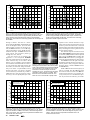
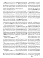
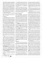
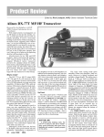
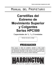
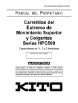
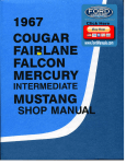
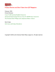
Product Review Column from QST Magazine
October 1997
Yaesu FT-920 MF/HF/6 Meter Transceiver
Tune in the World for Less Than $300: Drake SW1 and Radio Shack DX-394
Copyright © 1997 by the American Radio Relay League Inc. All rights reserved.
Product Review
Edited by Rick Lindquist, N1RL• Senior Assistant Technical Editor
Yaesu FT-920 MF/HF/6 Meter Transceiver
Reviewed by Bill Kennamer, K5FUV
DXCC Manager
The Amateur Radio transceiver has
changed substantially since its advent in the
1950s. Each generation has provided new
features that have gone from option to standard. Some of these, though revolutionary
for their time, have become commonplace.
The latest generation of transceivers feature expanded band coverage. Where once
80 through 10 meter coverage was standard
(with only a few offering 160 meters), most
manufacturers now offer at least one transceiver that at least covers 160 through 6, and
nearly all with general-coverage receivers.
The expanded coverage coincides nicely
with the beginnings of a new sunspot cycle,
and more countries of the world allow 6 meter
operation than ever before. Extended coverage plus more availability will increase activity on 6 meters throughout the world. The
new generation of transceivers will be ready
for this upsurge and may even drive it.
This leads us to the FT-920, Yaesu’s latest entry in the current generation and its first
“HF” transceiver to include 6 meters. The
’920, which replaces the FT-990 in the Yaesu
lineup, packs in a lot of features per dollar
and couples them with great performance to
boot. Some standard features, such as its digital voice recorder, are ones not found on other
units in this price class. Shuttle jog tuning,
which allows for rapid band excursions, is
another (it debuted on Yaesu’s more upscale
FT-1000MP, which the FT-920 somewhat
resembles). One standard feature we had not
seen before is the linear tuning pulse system.
This menu option provides a pulsed signal
(pulse and space times are menu-settable) for
low-duty cycle (ie, 15% or 20%) linear amplifier tuneup with full-power pulses! It’s
also possible to adjust power output and duration of the tuning signal.
The FT-920 provides 100 W output on all
bands, including 6 meters. It has MOSFET
power amplifiers in the transmitter’s final
stage.
Other standard features, such as the automatic antenna tuner and the CW keyer, have
come to be considered almost necessities.
With the exceptions of FM and transmit on
AM (both require optional boards), the
FT-920 offers a pretty complete package.
Little remained on my “wish list” once I’d
had a chance to get familiar with it.
This brings up one point that should be
made about this transceiver: you need to read
the instruction manual first, not only to get
72
October 1997
optimum performance, but to get it on the air.
It’s entirely possible for a new owner to
manipulate this radio to the point where you
won’t hear anything at all if enough knobs
are turned the wrong way!
Up Front
This is a pretty busy panel, with 79 buttons or controls to contend with (all the more
reason to study the manual). Once you get
the gist of it, however, it’s not as intimidating as it might first appear. Pushing the power
switch brings forth the orange light of the
Omni-Glow LCD display, which indicates
most of the radio’s functions. In some cases,
the only way you can be sure a particular
function is engaged is to check the display.
The FT-920’s display features nice, big numbers—approximately 3/8 -inch high—for the
VFO A and VFO B readouts. I found the display could be seen from any angle in any
room lighting condition, including bright
sunlight.
The main VFO A tuning knob dominates
the center of the radio. The outer part of the
concentric main tuning knob includes the
shuttle jog control, a feature we first saw on
the FT-1000MP. You simply twist the ring to
one side or the other for rapid frequency excursions, and the tuning speed depends upon
BOTTOM LINE
The FT-920 offers lots of standard
features per dollar for a radio in this
price class, including a digital voice
recorder and terrific DSP—plus excellent receiver performance. Many of its
best features can be found in its extensive menu system.
how far you turn it. This is great for getting
from one end of a band to the other for contest search-and-pounce operation, but it does
take a little practice. Additionally, the main
tuning knob may be set to a fast, normal or
fine tuning rate, depending upon operator
preference, by pressing the STEP button to
the left of the tuning knob. The display shows
the rate. The STEP button can control the
tuning rate of either of the radio’s two VFOs.
Front-panel buttons set VOX or (MOX)
manual transmission mode. You must use the
menu to set VOX delay and gain or CW semi
or full-break-in. Both the headphone and key
jacks are stereo types. I got adequate headphone output with either the Heil ProSet or
the Yaesu YH-55 headsets.
The MIC GAIN, AF GAIN, RF GAIN and RF
PWR controls are clustered on the panel’s
lefthand side. A set of four stem controls are
along the bottom of the front panel: SQL
(squelch), COMP (speech processor compression level) GAIN (for the speech monitor) and
LEVEL (for the noise blanker). Pushbutton
switches interspersed in the same row let you
turn the processor, speech monitor and noise
blanker on or off. While the controls are
small, these are functions that don’t have to
be set very often, so their size is not necessarily a disadvantage.
Meter selection is via a pushbutton
switch. You can step through ALC, SWR,
COMP (compression level), VOLT and AMP
(and back to ALC). Being able to monitor the
supply voltage is great if you’re operating
from a storage battery in the field. The IPO
switch controls the Intercept Point Optimization, which essentially allows the operator
to switch out the receiver RF preamplifier.
Actually, the FT-920 has two preamps. One
is a JFET, which defaults for use on 160
Table 1
Yaesu FT-920, serial number 7F020059
Manufacturer’s Claimed Specifications
Frequency coverage: Receive, 100 kHz-30 MHz; 48-56 MHz.
transmit, 1.8-2; 3.5-4; 7-7.3; 10.1-10.15; 14-14.35;
18.068-18.168; 21-21.45; 24.89 -24.99; 28-29.7; 50-54 MHz.
Modes of operation: USB, LSB, CW, AM, FM, FSK, AFSK
Power requirement: Receive, 2.0 A (no audio); transmit,
22 A (max), 13.5 V (±10%).
Size (height, width, depth): 5.4×16.4×12.6 inches; weight, 25.3 pounds.
Measured in the ARRL Lab
Receive and transmit, as specified.
As specified.
Receive, as specified; transmit, 18.5 A, tested at 13.8 V.
Receiver
Receiver Dynamic Testing
SSB/CW sensitivity, 2.4 kHz bandwidth, default preamp on, 10 dB
Minimum discernible signal (MDS), 500 Hz IF filter at 8.2 MHz:
(S+N)/N: 150-250 kHz, –84 dBm; 250-500 kHz, –95 dBm; 0.5-1.8 MHz, Freq
Preamp off
Preamp on
–101 dBm; 1.8-24.5 MHz, –121 dBm; 24.5-54 MHz,–125 dBm.
1.0 MHz
–114 dBm
–121 dBm
3.5 MHz
–132 dBm
–139 dBm
14 MHz
–131 dBm
–138 dBm
50 MHz
–131 dBm
–137 dBm
AM sensitivity, default preamp on, 6-kHz bandwidth, 10 dB (S+N)/N:
10 dB (S+N)/N, signal 30% modulated with a 1-kHz tone,
150-250 kHz, 40 µV; 250-500 kHz, 32 µV; 0.5-1.8 MHz,
6-kHz filter: 1.0 MHz, preamp off, 2.7 µV, preamp on,
16 µV; 1.8 24.5 MHz, 2.0 µV; 24.5-54 MHz, 1.3 µV.
1.1 µV; 3.5 MHz, preamp off, 0.36 µV, preamp on, 0.18 µV;
52 MHz, preamp off, 1.51 µV, preamp on, 0.52 µV.
FM sensitivity, 12 dB SINAD, default preamp on: 28-29.7 MHz and
For 12 dB SINAD, preamp on, 12-kHz bandwidth:
50-54 MHz, 0.25 µV.
29 MHz, 0.30 µV, 52 MHz, 0.16 µV.
Blocking dynamic range: Not specified.
Blocking dynamic range, 500 Hz filter at 8.2 MHz default preamp
selection.
Freq
Preamp off
Preamp on
1.0 MHz
133 dB
129 dB
3.5 MHz
134 dB
129 dB
14 MHz
131 dB
129 dB
50 MHz
137 dB
120 dB
Two-tone, third-order IMD dynamic range:
Two-tone, third-order IMD dynamic range, 500 Hz IF
Not specified.
filter at 8.2 MHz, default preamp selection:
Freq
Preamp off
Preamp on
1.0 MHz
95 dB
83 dB
3.5 MHz
99 dB
96 dB
14 MHz
98 dB
97 dB
50 MHz
101 dB*
99 dB
Third-order input intercept: Not specified
Default preamp selection:
Freq
Preamp off
Preamp on†
1.0 MHz
+25.3 dBm
+9.6 dBm
3.5 MHz
+17.7 dBm
+5.3 dBm
14 MHz
+17.2 dBm
+8.9 dBm
50 MHz
+21.2 dBm
–2.5 dBm
Second-order intercept point: Not specified
14 MHz, tuner off, preamp off, +69 dBm, preamp on, +68 dBm;
14 MHz, tuner on, preamp off, +70 dBm, preamp on, +72 dBm.
First IF rejection: > 70 dB on HF; >50 dB on VHF.
14 MHz, preamp off, 73 dB, preamp on, 106 dB.
First IF image rejection: >70 dB on HF.
14 MHz, preamp off, 67 dB; preamp on, 80.2 dB.
FM adjacent channel rejection: Not specified
At 20-kHz spacing, 29 MHz, preamp off, 77 dB,
preamp on, 71 dB; 52 MHz, preamp off, 75 dB, preamp on, 69 dB.
FM two-tone, third-order IMD dynamic range:
At 20-kHz spacing, 29 MHz, preamp off, 80 dB, preamp on, 70 dB;
Not specified
52 MHz, preamp off, 78 dB, preamp on, 70 dB.
S-meter sensitivity: Not specified
S9 signal at 14 MHz: preamp on, 50 µV.
Squelch sensitivity: SSB, CW, RTTY, AM, preamp on, less than 2.0 µV; At threshold, FM, 29 MHz, preamp on, 0.12 µV; 50.2 MHz,
FM, preamp on, less than 0.32 µV.
preamp on, 0.07µV; SSB, 14.2 MHz, preamp on, 1.36 V.
Receiver audio output: 1.5 W at <10% THD into 4 Ω.
2.7 W at <10% THD into 4 Ω.
Expanded Product
IF/audio response: Not specified.
Range at –6 dB points, (bandwidth):
Review Report
CW-N (500 Hz IF filter): 309-933 Hz (624 Hz);
Available
CW-W (2.4 kHz IF filter): 219-1888 Hz (1669 Hz);
USB (2.4 kHz IF filter): 270-1930 Hz, (1660 Hz); The ARRL Laboratory
offers a detailed test
LSB (2.4 kHz IF filter): 279-2007 Hz (1728 Hz).
result report on the
Notch filter depth: >35 dB.
As specified.
FT-920 that gives inTransmitter
Transmitter Dynamic Testing
Power output: SSB, CW, RTTY, and FM, 100 W maximum,
SSB, CW, RTTY, and FM, as specified
AM, 25 W, continuously adjustable in all modes.
(1.2-107 W); AM, as specified.
Spurious-emission suppression: 50 dB (HF bands); 60 dB (50 MHz band). 53 dB or greater on HF; greater than 60 dB
on 50 MHz. Meets FCC requirements for
equipment in its power output class and
frequency range.
SSB carrier suppression: 40 dB.
50 dB or greater.
Undesired sideband suppression: 50 dB
As specified.
Third-order intermodulation distortion (IMD)
See Figures 1 and 2.
products: –31 dB or better at 100 W output.
CW keyer speed range: Not specified.
Approximately 6-62 WPM.
CW keying characteristics: Not specified.
See Figure 3.
Transmit-receive turnaround time (PTT release to 50%
PTT release to 50% audio output,
audio output): Not specified
S9 signal, 18 ms.
Receive-transmit turnaround time (“tx delay”):
SSB: 50% delay on, 15 ms;
Not specified.
FM: 50% delay on, 47 ms.
Composite transmitted noise: Not specified.
See Figures 4 and 5.
Note: Unless noted otherwise, all dynamic range measurements were taken at the ARRL Lab standard of 20 kHz.
†Third-order intercept point was determined using S5 reference.
*Measurement was noise-limited at the value indicated.
depth, technical data
on the transceiver’s
performance, outlines
our test methods and
helps you interpret the
numbers and charts.
The report even
includes a summary
of how this radio
stacks up with similar
previously tested
units.
Request the FT-920
Test Result Report
from the ARRL
Technical Department, 860-594-0278.
It’s $7.50 for ARRL
members and $12.50
for nonmembers,
postpaid.
October 1997
73
0
0
Reference Level: 0 dB PEP
Reference Level: 0 dB PEP
–10
–10
–20
–20
–30
–30
–40
–40
–50
–50
–60
–60
–70
–70
–80
–10
Y
–8
FT 920 HF T
–6
–4
–2
0
2
4
Frequency Offset (kHz)
6
8
–80
–10
10
i
Y
Figure 1—Worst-case spectral display of the FT-920 transmitter
during two-tone intermodulation distortion (IMD) testing on HF. The
worst-case third-order product is approximately 25 dB below PEP
output, and the worst-case fifth-order product is approximately
31 dB down. The transceiver was being operated at 100 W output at
24.950 MHz.
through 15 meters. The other is a lowernoise, dual-gate MOSFET which defaults for
use on 12 through 6 meters. (You can select
which preamp you want via the menu system.) An ATTenuator has 6, 12 or 18 dB steps,
a big improvement on the 20-dB fixed attenuators of the past. The AGC switch is also
a step switch, and successive pushes go
through fast, slow, and off.
One nice touch a lot of operators will
appreciate is the front-panel ANTENNA
switch to switch between two antennas. Antenna selection stays in the radio’s band
memory, too. For example, connect antenna
A for 20 meters and antenna B for 6 meters.
As you switch back and forth between the
two bands, the antennas change automatically. Even better: a separate RX (receive)
antenna switch lets you choose a separate
receive antenna (or, alternatively, a VHF or
UHF transverter, receiving converter or other
accessory) via a rear-panel phono jack. This
–4
–2
0
2
4
Frequency Offset (kHz)
6
8
10
i
separate receive antenna function is especially well-executed. A menu option lets you
choose to protect the transceiver’s front end
against pickup of stray RF from the transmitter by switching the receiving antenna out of
the line during transmit.
The radio has separate switches for each
mode: SSB , CW , AM (optional board required
for transmit), FM (available with the optional
FM-1 board), and DATA (FSK or AFSK). The
SSB and CW buttons also let you toggle between the desired sideband for those modes.
The LOCK switch to the right of the VFO
knob allows locking the VFO A frequency—
a handy feature when youngsters walk into
Figure 3—CW keying waveform for the FT-920
showing the first two dits in full-break-in (QSK) the shack (there’s another LOCK button for
mode. The equivalent keying speed is 60 WPM. the VFO B knob).
The A—>B button moves the frequency of
The upper trace is the actual key closure; the
lower trace is the RF envelope. Horizontal
VFO A to VFO B. The A<—>B knob swaps
divisions are 10 ms. The transceiver was being the contents of the two VFOs. The RPT butoperated at 100 W output at 14.2 MHz. Note
ton allows the operator to set a repeater offthat both dits are somewhat shortened. This
set (by menu) for 29 or 52 MHz FM operadoes not occur in semi-break-in (VOX) mode.
tion. If you need a CTCSS tone, you set this
–60
Reference Level: - 60 dBc/Hz
Vertical Scale: dBc/Hz
–70
–80
–90
–90
–100
–100
–110
–110
–120
–120
–130
–130
Y
4
FT 920 HF T
6
8
10
12
14
16
18
20
Frequency Sweep: 2 to 22 kHz from Carrier
22
i
Figure 4—Worst-case tested spectral display of the FT-920
transmitter output during composite-noise testing on HF. Power
output is 100 W at 3.5 MHz. The carrier, off the left edge of the
plot, is not shown. This plot shows composite transmitted noise
2 to 22 kHz from the carrier.
74
FT 920 HF T
–80
–140
2
–6
Figure 2—Spectral display of the FT-920 transmitter during two-tone
intermodulation distortion (IMD) testing on 6 meters. Third-order
product is approximately 27 dB below PEP output, and fifth-order
product is approximately 33 dB down. The transceiver was being
operated at 100 W output at 50.2 MHz.
–60
–70
–8
October 1997
–140
2
Y
Reference Level: - 60 dBc/Hz
Vertical Scale: dBc/Hz
4
FT 920 HF T
6
8
10
12
14
16
18
20
Frequency Sweep: 2 to 22 kHz from Carrier
22
i
Figure 5—Spectral display of the FT-920 transmitter output
during composite-noise testing on 6 meters. Power output is 100
W at 50.2 MHz. The carrier, off the left edge of the plot, is not
shown. This plot shows composite transmitted noise 2 to
22 kHz from the carrier.
via the menu.
The DW button activates the Dual Watch
function. Dual watch sets the radio up to periodically check the VFO B frequency for
activity while you’re tuned to VFO A. In
theory, this sounds great. In practice, using
dual watch requires enabling the squelch.
This means that you hear nothing on either
frequency unless there’s a signal. When the
radio hears a signal on the VFO B frequency,
it breaks the squelch and goes to that frequency. Some users were disappointed to find
out that this was not a true dual-receive function, but more like a priority scanning system. Since it works only while the receiver is
squelched, it might be useful for times when
the operator is otherwise occupied.
A keypad dominates the area to the immediate right of the VFO A (main tuning) knob.
It’s used primarily for one-touch band selection. The FT-920 stacks the last two sets of
parameters for each band into memory registers. You also can use it for direct frequency
entry on either VFO, and it controls memory
selection for the digital voice recorder and
the CW memory keyer. For FM, the keypad
serves as a DTMF keyboard.
The REC and PLAY buttons work for both
the digital voice recorder and the CW memory
keyer. The radio has UP and DOWN keys for
rapid frequency excursions or to step through
the memories—whichever is selected.
Green RX and red TX light/button combinations flank both VFO knobs. Pressing one
or the other sets the VFO in use for either
transmitting or receiving. These replace the
“split” buttons on many other transceivers
and are very intuitive. Just touch the one you
want for transmit or receive. This should
minimize use of the wrong VFO in pileups
and contests!
Beneath the VFO B tuning knob are the
clarifier (RIT) and keyer controls. RX and TX
clarifier may be selected independently, and
the CLEAR button lets you return to the original frequency. Clarifier tuning is via the VFO
B tuning knob; users were split on whether
they liked this doubling up.
Momentarily pressing the TUNER switch
activates the automatic antenna tuner, which
can be enabled via the menu to work on receive, if desired. Holding the button in for a
half second activates the automatic matching mode. The tuner works on all bands, including 6 meters. It operates very quickly and
quietly.
Yaesu says the tuner can match from approximately 17 to 150 Ω. Power is automatically reduced to 50 W while tuning. The LCD
display indicates the tuner’s operation, and
mode (TX, RX or both). The tuner automatically stores settings of less than 1.5:1 SWR,
but does not store those above that level. This
prevents storing an undesirable setting, such
as inadvertently trying to tune your 20 meter
antenna on 10 meters.
The FT-920 also has IF SHIFT . The control has a range of ±1.2 kHz.
Controls involved with CW operation are
clustered along the lower right apron. A
SPOT switch activates a spotting tone to zero
beat CW signals (set the level using the
SIDETONE knob). Having the sidetone level
on the front panel was a nice touch; too often,
this is hidden away inside or on a menu somewhere. A PITCH control adjusts CW offset in
50-Hz steps between approximately 300 and
1050 Hz. Switches control the CW keyer and
selection of full CW break-in operation, and
there’s a small pot for keyer speed control.
Most users felt the VFO B and DSP knobs
obscured the clarifier and keyer controls,
making them harder to use.
Thanks for the Memories
The FT-920 has 99 standard memories,
five quick memory bank (QMB) memories, 10
split-frequency channels, 11 call channels and
a set of band-edge memories for programmable memory scanning. In addition to operating frequency and mode, standard and split
memory channels can store filter bandwidth,
clarifier (RIT) information, antenna selection,
antenna tuner status, repeater shift, CTCSS
tone, alphanumeric labels and lock switch status (some restrictions apply on what can be
stored in QMB and band-edge memories).
Press the QMB STO button to store up to
five “quick memories,” which are stacked as
they are entered and recalled by pressing the
QMB RCL button until the desired memory
appears. This is great for contesting or for the
DXer who wants to check multiple pileups.
A few reviewers cited the QMB memories
among those features they liked most. It’s a
feature I also found handy.
The MEM CH switch changes the VFO B
knob from VFO operation to memory channel selection. You can divide the standard
memory area into as many as four groups, if
you like. The MEM GROUP switch accesses
memory channels within a designated group,
to reduce selection time if you only need to
keep an eye on a few particular channels.
You can apply seven character alphanumeric names to all memory channels except
the quick memory bank channels. The DISPLAY button lets you swap the VFO B frequency display for alphanumeric memory
names the operator may have plugged into
memory.
DSP Delights
The DSP works at audio frequencies
rather than at a low-frequency IF, as it does
in some other transceivers (including big
brother FT-1000MP). Execution of the DSP
functions was excellent.
The heart of the radio’s DSP features is a
prominent set of concentric LOW CUT/HIGH
CUT controls on the righthand side of the
panel. You activate this part of the DSP by
pushing the DSP button, then use the LOW
CUT/HIGH CUT to set your passband cutoff
frequencies. Many users found this implementation very convenient, and the DSP
worked so well you had to remind yourself
that it was only working at audio and after the
AGC. As Yaesu points out in the FT-920
manual, strong signals outside the DSP passband still can pump the AGC. The LOW CUT/
HIGH CUT controls are designed to move
through half rotation for best results, and I
preferred the HIGH CUT control at 12 o’clock
and the LOW CUT control at 8 o’clock. These
settings conformed the passband to my tastes,
both on CW and SSB.
Through a menu setting, you can have the
display provide a graphical representation of
the relative audio passband. The NOTCH button activates the automatic DSP notch, handy
for nulling out those pesky carriers on SSB.
You don’t have to push the DSP button to use
it. The notch captures the offending heterodynes and lowers them to a tolerable level—
in most cases totally eliminating them.
Touching up the LOW CUT/HIGH CUT controls can eliminate any residual heterodynes
in most cases. The lack of an IF notch may be
a problem on CW for some operators.
The NR knob adjusts the level of the DSPbased noise reduction—super for cutting
down on “background” noise. Again, you
don’t have to press the DSP button to enable
noise reduction. Simply rotating the front
panel control brings it into play, and the receiver is most comfortable to listen to with at
least a little bit cranked in. The DSP NR can
help reduce operator fatigue during long operating periods.
Digital Voices
It was a pleasant surprise to find a digital
voice recorder as a standard feature of this
midrange radio. It’s something you’d certainly expect to find only in a top-of-the-line
set. The DVR records both incoming audio
(16 seconds worth) plus four outgoing messages. To record incoming audio, you touch
the REC button, then the 50 MHz key on the
keypad. The received audio plays through the
monitor—so you can bask in the glow of
hearing that rare DX station you just worked
come back to you again and again.
Recording outgoing messages is easy, but
the instructions in our FT-920 manual were
incorrect, and when we’d attempt to air the
message, it would hang up for several seconds in transmit. After Yaesu told us that the
correct way to stop recording was to press
the REC button again, the message would
play back properly. The manual indicates
that outgoing message buffers are 16 seconds
apiece. We timed two buffers at approximately 8 seconds each and two at approximately 4 seconds each, however.
Some users did not like the fact that you
had to first momentarily press the PLAY button, then quickly select the proper memory
buffer to air your message. If you don’t press
the memory key (1-4) fast enough, the
memory key will revert to its original function, and you’ll probably find yourself on
another band altogether.
It is not possible to control the digital
voice recorder via computer.
For audio processing, the FT-920 uses a
digital speech compressor at audio level. This
is a break with Yaesu tradition, as most past
offerings have used RF clipping. Activating
the PROC switch and adjusting the compression level is all that is necessary for adjustment. We found that turning the COMP control to around 3 o’clock yielded optimum
results.
In addition to the audio processor, you
can use the menu to select four different DSP
voice pattern contours. On the air reviews
were mixed on how well the four digital conOctober 1997
75
tours did their job in tailoring transmit audio.
Consensus was that audio level appeared to
drop off on all four settings; you had to compensate with higher gain level or by using a
bit more compression. The high-emphasis
selection successfully produced “contest”
type audio to cut through QRM; the changes
wrought by the other settings were more
subtle. But several stations said they thought
the audio sounded “best” in the default position, with the digital equalization turned off.
The manual seems to say that you have to
enable the DSP system via the front panel in
order to take advantage of this feature, but
we found this to be incorrect.
The speech monitor comes in handy while
using the digital voice recorder during contests. The clarity of audio through the FT-920
monitor was excellent.
To the Rear
The back panel is where the FT-920 shows
its practical side. Most connections use standard phono (RCA) connectors, so many setups can avoid having to solder those dreaded
DIN connectors (one DIN jack provides TX/
RX switching and band data for use with a
Yaesu FL-7000 linear). SO-239 connectors
are provided for both ANT A and ANT B .
For computer control, you make the connection to the CAT port via a standard DB-9
female connector (cables with the proper
connectors are available at most Radio Shack
stores). The rear panel also provides an additional (stereo) KEY jack, used in conjunction with the rear-panel PDL-KEY switch,
which lets you use an external keying device
(a hand key or computer, for example) and
the built-in keyer at the same time—a great
idea and something that contest operators
certainly will appreciate. This allows use of
the popular contest programs for keying contest exchanges, while the internal electronic
keyer itself may be left on, and paddles connected through the front jack, for sending
fills by key—a boon for the non-typists
among us.
The rear panel also provides a PTT jack
for use with a foot switch or other type of
remote switching plus a TX GND jack for
amplifier switching. There are two possibilities for its use: With the TR-RY switch set in
the “RY” (relay) position, a relay capable of
switching 125 V at 500 mA is used, so you
can safely switch your old SB-220. For
break-in use with some amplifiers, the “TR”
position employs a quiet transistor switch,
rated at 50 V dc at 500 mA.
Another jack provides 13.5 V at up to
200 mA for accessories. You’ll also find an
EXT SPEAKER jack (3.5 mm, two-conductor) and an AF OUT jack for low-level audio
recording, TNC, or WEFAX. It provides 100
mV into a 600-Ω and the level is not controlled by the front panel AF GAIN control. A
similar jack for PATCH input is independent
of the MIC GAIN control.
There’s an FSK-AFSK switch for digital
operation. A five-pin DIN connector (the
only other one, thankfully) is available for
data input.
The ALC connection is provided via an
RCA jack.
76
October 1997
We already mentioned the separate receive antenna jack. While the FT-920 does
not offer a transverter port as such, the Operating Manual includes information on how
to use the RX jack and/or one of the SO-239
antenna connectors to accommodate a
transverter.
Overall, the back panel offers ample flexibility. The only drawback is that, except for
the antenna and power connections, nothing
on the rear panel is marked. A legend affixed
to the top panel of the radio provides a map
to all connections, but it’s difficult to refer to
this chart when the radio is beneath a shelf
and the operator is behind it!
May I see the Menu?
Overall, operation is straightforward.
Some users got the hang of the FT-920 without spending a whole lot of time with the
manual, which, as we’ve already noted, contained a few errors (Yaesu says it’s working
on these). But some features are not terribly
obvious, and many of the radio’s best features only are accessible through the menu
(shades of the FT-1000MP). For best results,
it’s wise to pay special attention to the section of the manual that describes the 73 menu
functions.
The MENU switch activates the menu
mode and allows customization of many parameters. Normal menu operation is simple.
Just press the MENU button, dial up the desired function with the VFO B knob, press
the ENT key on the keypad, use the VFO B
knob to set the desired parameter, press ENT
again, and MENU to exit.
A handy panel menu feature retains five
frequently used menu items for quick recall,
including the display dimmer, VOX hang
time in CW, multi-panel display choice, enhanced tuning scale display, and CTCSS tone
frequency. In addition, the FT-920 has a
quick menu option that lets the user pick out
certain menu items for quick and easy access. This quick menu bank operates almost
identically to the normal menu mode except
it only gives you the menu items you’ve
asked to make available. To get to the quick
menu, you press the MENU button momentarily; to access the normal menu, you hold in
the MENU button for one-half second. Pretty
nifty.
On the Air
While the profusion of knobs and buttons
on the front panel might suggest a steep learning curve, the FT-920 is really pretty simple
to use.
For instance, for SSB operation, just
touch the SSB button. The LCD display
shows which sideband has been selected.
While the default is according to convention
(LSB below 10 MHz, USB above), you can
swap sidebands by pressing the ENT button
again. Adjust the MIC GAIN control for proper
ALC metering, and you’re all ready to go.
VOX operation is smooth. There are two
different menu settings available, one for
voice, the other for semi-break-in CW.
The FT-920 provides effortless CW operation, both semi-break-in and full-breakin (QSK). Full-break-in CW was free of the
pops found in some radios, and it was possible to hear between dits at 35 WPM or so.
When using a non-QSK linear amplifier,
you’ll want to use semi-break-in with the
proper VOX adjustment. It’s easy to adjust
the delay for just the right balance between
fast transition to receive and absence of relay
chatter.
We did notice we could still hear a very
strong CW signal on the opposite side of zero
beat, even with the 500-Hz filter enabled. The
opposite side signal was down by more than
50 dB, however.
Receiving with the radio was a pleasure.
It handled strong signals well, but the combination of a good basic receiver with DSP
resulted in excellent overall performance for
a radio in this price class (see Table 1). Two
filters are available as options: a 500-Hz CW
filter and a 6-kHz AM filter. The radio can
only accommodate these filters, and Yaesu
does not offer an optional narrow SSB filter.
We found out that you must install the
AM filter in order to transmit on AM (Yaesu
now offers a free “pass-through” board that
enables AM transmit). Our unit had both filters installed, and filtering was very good,
although the AM filter is too narrow for suitable AM broadcast reception. On CW, you
can further reduce the bandwidth by using
the DSP, and the combination of the two provided excellent single-signal CW reception.
By the way, the FT-920 receiver is
double conversion on HF (68.985 MHz and
8.215 MHz). The accessory filters are in
the 8.2 MHz IF. The radio is triple conversion only on FM, where the lowest IF is at
455 kHz.
The CW memory keyer works well, but
some users felt its two-button operation was
less than convenient. The keyer allows for
automatic character spacing to be enabled or
disabled, or use as an electronic “bug” type
key. Especially noteworthy was the fact that
you can adjust dot and dash lengths (ie,
weighting) separately, not just the dot-todash ratio. The keyer has six memories, and
it permits sequential contest serial numbering. The primary drawback is that, as with
the digital voice keyer, you have to press the
PLAY button, then (quickly) the memory
number to air a message. On the other hand,
the CW memories may be controlled by a
computer program.
The noise blanker worked well against
electric motor noise. At my place, there is
usually no noise, so I generated some S9
noise by turning on a vacuum cleaner. The
blanker reduced the noise to a negligible
level. Other users also found the noise
blanker to be very effective, especially in
combination with the DSP noise reduction.
When our unit first arrived, it exhibited a
strange hissing or buzzing sound (sort of like
a small nest of tiny hornets) whenever the
noise blanker was engaged and the MONI
LEVEL control was turned up (it made no
difference if the monitor was engaged or not).
We returned our unit to Yaesu, which determined that some earlier production units like
ours suffered a crosstalk problem. Yaesu
fixed our FT-920 and says it has corrected
this problem in subsequent production units.
Somewhat disconcerting were the results
of the transmit intermodulation distortion
(IMD) tests (see Figures 1 and 2). Almost as
disturbing as the prominence of third and fifthorder products was the prominence of higherorder (ie, seventh, ninth, eleventh) products.
Yaesu specified a third-order IMD figure of
–31 dBc (see Table 1), a specification it met
on 15, 17, 20, 40, 80 and 160 meters, where
IMD performance was much better but not
spectacular. For comparison, the best case
was 40 meters, where third-order products
were 32 dB down, and fifth-order were 45 dB
down, and higher-order products were almost
non-existent.
On HF, the ARRL Lab measured worstcase performance on 12 meters, where thirdorder products were just 25 dB down and fifthorder 31 dB down. That’s marginal in
comparison to other transceivers in this price
class that we’ve looked at recently. Exacerbating this performance was the fact that
higher-order products do not drop below
50 dB until the 13th order!
The worst-case performance on 50 MHz
was only a shade better. Third-order products
were down by 27 dB and fifth-order products
by 33 dB, but, once again, higher-order products remain prominent through the 13th order.
As we’ve said in past reviews, this is the
kind of IMD performance that may lead to
problems with splatter and “wide” signals, especially when the transceiver is used with an
amplifier.
The ARRL Lab measured comparable IMD
performance on a second FT-920. This marginal IMD performance was the only serious
problem we encountered with this transceiver.
Yaesu advised that its production units as
of mid-August were “displaying less variation
in performance, due to tightening of production part tolerances.” Yaesu supplied one of
these units for us to test. The unit barely met
its third-order IMD specification on the HF
bands but not on 6 meters; higher-order products overall were less prominent, however.
Additional Observations
The reactions of several users appear to
prove out the proverbial notion that “you can’t
please all of the people all the time.” Take the
radio’s ergonomics, for example. One user
called the ergonomics “some of the best of
the radios I have recently used,” while another
called the front panel “awkwardly laid out”
and the radio “not as comfortable to operate”
as others he’d used. For my part, I tend to
feel that the rig is generally comfortable, ex-
Tune in the World for Less Than $300!
Drake SW1 and Radio Shack DX-394
Reviewed by Rick Lindquist, N1RL
Senior Assistant Technical Editor
and Bill Moore, NC1L
Century Club Manager
One of the surest routes to ham radio over
the years has been shortwave listening
(SWLing) and broadcast listening (BCLing).
Very often, the fascination of listening to
broadcasts and other transmissions from faroff places has led to a desire on the part of
listeners to put a signal of their own on the
air. We looked at a couple of economical
receivers for the beginning SWL or BCL to
consider that won’t put you in hock but can
offer hours of listening fun, the Drake SW-1
Shortwave Receiver and the Radio Shack
DX-394 Communications Receiver.
Drake and Radio Shack have been making receivers for novice and veteran SWLs
and BCLs for years (decades in the case of
Drake, which recently re-entered the Ama-
teur Radio market). In the past, we’ve looked
at the Radio Shack DX-302 receiver (see
“Product Review” QST Aug 1981) and the
Drake R7, R8 and SW8 receivers (see “Product Review”, QST, Jan 1980, Mar 1992, and
Oct 1994, respectively).
Both of these receivers are tabletop sets
designed primarily for installing in a home
listening post. Both are equipped to operate
from 120 V ac, have built-in speakers and
digital displays. Both cover the standard
broadcast (530-1710 kHz) and shortwave
bands—and then some. But perhaps the best
part is that each receiver sells for less than
$300.
Drake SW1
The SW1 designation says it all. This is
Drake’s entry-level receiver, and these days,
you won’t find a set much more basic and
down-to-earth than the Drake SW1. This is a
cept for the location of the clarifier and keyer
controls.
Users were ambivalent about the doubleduty VFO B knob for the VFO and for RIT. One
tester found that this scheme “worked out
much better than I would have thought,” while
another said it was “awkwardly shared with
the VFO.”
Overall, I enjoyed using this radio. In comparison to what was available 10 or 15 years
ago in price and performance, the
FT-920 shows that it’s possible to increase
value in greater proportion to price. The ’920
offers lots of standard features and performance, and it’s a worthy contender among the
other offerings in this price category.
Many thanks to Randy Thompson, K5ZD;
Emil Pocock, W3EP; Larry Wolfgang, WR1B;
Rick Lindquist, N1RL; and Mike Tracy,
KC1SX, and Ed Hare, W1RFI, of
the ARRL Lab for their contributions to this
review.
Manufacturer: Yaesu USA, 17210
Edwards Rd, Cerritos, CA 90703; tel 310404-2700. Manufacturer’s suggested retail
price, $2300; 500-Hz YF-116C CW filter,
$127; 6-kHz YF-116A AM filter, $127; FM-1
FM board, $62; TCXO-7 temperature-compensated oscillator, $99.
fairly compact, utilitarian, lightweight box
(except for the plastic front panel, the cabinet is steel) with a front-firing speaker on the
left and a big green LED display on the right
above the TUNING knob. The radio continuously covers from 100 kHz to 30 MHz. It’s
double conversion, with IFs at 45 MHz and
455 kHz. There are controls for RF GAIN and
VOLUME, plus a 16-button keypad (that includes the power and display dimmer buttons) and big up and down buttons labeled
with arrows. AGC is fixed. You’ll find the
mini-phone jack on the lefthand panel for
headphones. Drake did not provide a signalstrength indicator of on the SW1. That’s unfortunate, since an S meter is a staple for
hobby listeners.
The US-made SW1 receives one mode—
AM. It has 32 programmable memories to
save frequency settings (it comes from the
factory pre-programmed with SW stations),
and you can enter frequencies directly from
the keypad. Hook your antenna to the rear
panel (the SW1 has an SO-239 for a coaxialfed connector or a set of screw terminals for
a wire antenna and a ground connection), and
apply power and you’re all set. To help get
you started, Drake supplies a little wire antenna with the SW1 that’s suitable for a temporary indoor setup. The SW1 can operate
from 12 V dc into the coaxial power connector on the rear panel. An ac “wall cube”
adapter is supplied for typical home use, but
the dc capability makes it handy for use away
from home (or even in an emergency).
As an AM-only receiver, the fact that the
smallest tuning increment is 1 kHz is not necessarily a hardship (the radio tunes in 5-kHz
steps using the up/down keys). The syntheOctober 1997
77
Table 2
Drake SW1, serial number 6H12910064
Manufacturer’s Specifications
Measured in ARRL Lab
Frequency coverage: 100 kHz-30 MHz.
As specified
Modes of operation: AM.
As specified.
Power requirements: 120 V ac; 12 V dc at 400 mA. As specified.
Size (HWD): 4.4×10.9×7.6 in; weight, 4.7 lb.
Sensitivity (bandwidth not specified):
AM, test signal modulated 30% with
2.0 µV or less (typical).
a 1-kHz tone. 10 dB (S+N)/N:
100 kHz, 10.5 µV; otherwise,
as specified.
Blocking dynamic range: Not specified.
14 MHz, 87 dB (noise-limited) at
100-kHz spacing.
Two-tone, third-order IMD dynamic range:
14 MHz, 72 dB (noise-limited) at
Not specified.
100-kHz spacing.
First IF rejection: Not specified.
58 dB.
First IF image rejection: Not specified.
67 dB.
IF/audio response: Not specified.
Bandwidth at −6 dB points: 4500 Hz.
Audio power output: Not specified.
245 mW @ 10% THD into 8 Ω.
NOTE: All dynamic range measurements were taken at 100 kHz, instead of at the ARRL
Lab standard of 20 kHz.
sized SW1 does exhibit some “synthesizer
chuffing” when tuning manually, but getting
where you want to go is extremely simple via
the TUNING knob, up/down buttons or direct
entry. A nice feature was the automatic frequency entry. Punch in a frequency and the
SW1 will automatically enter the frequency
(after a slight pause if the frequency has fewer
than five digits)—or you can just press the
ENTER key if you’re in a hurry.
It’s also very easy to save stations to
memories—too easy, in fact, because the
SW1 does not warn you that you’re overwriting a given memory channel—but we sometimes found ourselves wishing for a few more
memories. You could quickly fill up all 32 in
a single sitting on the broadcast or shortwave
bands. An 11-page Owner’s Manual comes
with the SW1, but the radio is quite intuitive.
We had the whole thing figured out even
before we looked at the book—including how
to program the memories.
The sound from the SW1 was pretty astounding for such a little set, although it delivers less than 1 W to the speaker. The audio
had a nice rich balance especially suited for
AM broadcasts, but AM operators on the ham
bands sounded terrific on the SW1, too. On
the AM broadcast band, the 5-kHz steps on
the SW1’s up/down keys made tuning across
the standard 10-kHz channels very convenient, yet you still could listen for those stations in other countries that are sandwiched in
between our 10-kHz channels. With a fairly
large antenna attached, the receiver did a creditable job of separating the AM channels and
keeping splatter or adjacent-channel spillover
to a minimum, even in the neighborhood of
strong local stations. On shortwave, there was
an undercurrent of noise that likely was the
result of various mixing products developed
in the receiver and just plain poor dynamic
range (see Table 2). For example, even in the
vicinity of 29 MHz—relatively quiet at this
point in the solar cycle—we could detect various shortwave broadcasting signals that were
78
October 1997
elsewhere in reality. Connecting a resonant
antenna reduced this effect significantly. Using an antenna tuner might also help.
We found the RF GAIN and VOLUME
knobs a bit wobbly. Also, the RF GAIN control did not seem to have the expected effect.
It appeared to be more of an attenuator than
an actual RF gain control.
Manufacturer: R. L. Drake Co, 230 Industrial Dr, Franklin, OH 45005; tel 513746-4556; fax 513-743-4510. Manufacturer’s suggested retail price, $299.
Radio Shack DX-394
This is Tandy’s top-of-the-line generalcoverage receiver, the latest of its type in
Radio Shack’s consumer electronics lineup.
Since it debuted on the market, the DX-394
has gone through two updates, identified by
an A or B suffix after the model number on the
back panel. When we purchased our DX-394,
our local Radio Shack store still had A-suffix
models in stock, and that’s what we tested.
The A-suffix units include decreased gain of
the second mixer, extended AGC release time,
and modified audio compensation for SSB.
The DX-394 touts lots of features, especially considering its price class: continuous
coverage from 150 kHz to 30 MHz; AM,
SSB, and CW modes; 160 frequency memories; digital readout; dual clocks; a mikelevel tape-recorder output; search and scan;
and direct frequency entry from its frontpanel keypad.
This is a compact set in a charcoal-gray
plastic cabinet with two fold-down front legs.
It features a large LCD display, five frontpanel controls, plus a bunch of push buttons—including a keypad. Like the SW1, this
set is a dual-conversion superhet (the IFs also
are 45 MHz and 455 kHz) with PLL synthesized tuning. You can dim the green-background display but you won’t want to. The
DX-394 has a built-in power supply, so you
can plug it right into the wall outlet. It also
can run off 13.8 V dc, and it has a little built-
in telescoping whip antenna on top of the
case, making it fairly portable.
Front-panel push buttons let you jump
immediately to any of the international
shortwave broadcasting bands—from 120 to
11 meters (the 11-meter BC band is right
below the 11-meter Citizens Band). The display clearly shows which BC band you’re
listening to (ie, 41 m, 19 m). There’s a frontpanel mini-jack for headphones.
You can set the tuning step size (100 Hz,
1 kHz, 5 kHz or 10 kHz) using two frontpanel STEP keys, and it displays the selection on the front panel (9-kHz AM channel
spacing used in some parts of the world is
available as a power-up option). Programmable timers let you store frequencies and
on/off times. The front panel also includes a
digital replication of an analog S meter. AGC
is not adjustable.
Using the manual tuning knob can be a
little squirrelly, since the actual tuning rate
varies with the speed with which the knob is
spun (something the Owner’s Manual did not
explain). Tune very slowly and carefully, and
it covers approximately 2.5 kHz per rotation
when you’re set to the smallest tuning step
(100 Hz). Spin it very rapidly and you’ll
move up or down 15 or 20 kHz or more in
short order. A continuous-tuning FINE TUNE
control gives you somewhat greater control,
covering approximately 2 kHz per rotation,
independent of step size.
The rear panel includes connections for a
high- or low-impedance antenna, an extension speaker, tape out, and external dc power.
It also has a recessed button to perform a hard
microprocessor reset. The set also has a rearpanel 20-dB ATT enuator switch, which we
left on when the set was connected to an external antenna; it engages a passive attenuator. Hooking it up to an external antenna is
neither necessary nor especially desirable,
except that an external antenna might be less
prone to pick up household interference. The
noise blanker was not very effective in reducing interference from an oil-burner igniter.
The DX-394 is ultra-simple to use. Just
plug it in, extend the little antenna on top, turn
it on, set the MODE switch, VOLUME and RF
GAIN controls and tune away. The DX-394
gives you several ways to tune in stations. You
can manually tune them in using the main
tuning knob, reading the frequency right off
the display. Manual tuning was accompanied
by synthesizer “chuffing” typical of inexpensive sets like this. You also can directly enter
a frequency via the keypad on the front panel.
Or you can use the unlabeled arrow keys. In
addition, the radio’s search mode will automatically look for the next strong signal, although you probably will want to first turn
down the RF GAIN control, as the Owner’s
Manual suggests. Otherwise, the radio might
mistake whatever noise it’s hearing for a signal and not start searching.
Among the best features of the DX-394 is
its memory system. It’s very easy to store a
frequency (and only a frequency) in one of the
memories. The DX-394 sets aside 10 memories for each of the bands (LW, MW and SW),
plus 10 apiece in each of the “meter” bands,
Table 3
Radio Shack DX-394, serial number, C004541
Manufacturer’s Specifications
Measured in ARRL Lab
Frequency coverage: 0.15-30 MHz.
As specified.
Modes of operation: LSB, USB, AM, CW.
As specified.
Power requirements: 120 V ac, 13 W; 13.8 V dc, 300 mA.
Size (height, width, depth): 3.8×9.2×9 inches; weight, 4.6 lb.
SSB sensitivity, bandwidth not specified,
As specified.
10 dB (S+N)/N, 1.7-30 MHz, 0.3 µV.
CW sensitivity, bandwidth not specified,
As specified.
10 dB (S+N)/N, 1.7-30 MHz, 0.1 µV.
AM sensitivity, bandwidth not specified,
10 dB (S+N)/N, signal 30% modulated
10 dB (S+N)/N: 150-510 kHz, 10 µV;
with a 1-kHz tone: As specified.
510-1730 kHz, 7 µV; 1.7-30 MHz, 1 µV.
Blocking dynamic range: Not specified.
14 MHz, CW1 position, 104 dB at
100-kHz spacing.
Two-tone, third-order IMD dynamic range:
14 MHz, CW1 position, 84 dB at 100-kHz
Not specified.
spacing.
First IF rejection: 80 dB (50-Ω antenna).
67 dB.
First IF image rejection: 80 dB (50-Ω antenna). 70 dB.
IF/audio response: Not specified.
Bandwidth at –6 dB points: CW1, 333 Hz;
CW2, 328 Hz; USB, 2059 Hz;
LSB, 2111 Hz; AM, 9520 Hz.
Audio output: 0.8 W at 10% THD into 8 Ω.
1.1 W at 10% THD into 8 Ω.
NOTE: All dynamic range measurements were taken at 100 kHz, instead of at the ARRL Lab
standard of 20 kHz.
like 49 or 31 meters—160 memories in all. Of
course, this can make for a little confusion
when you’re trying to recall which set of 10
memories you’re operating with at any given
moment. A separate MON button lets you store
and recall a frequency in a “scratchpad”
memory. An internal, rechargeable cell backs
up memories a month or more, when power is
removed from the receiver.
On any given evening—especially here
in the Northeast—the 40-meter amateur
phone band (41-meter SW BC band) can be
a radio listener’s nightmare, particularly for
a receiver lacking in dynamic range. Of
course, we put the DX-394 to that test. While
the needle-pinning AM broadcast stations
dominated the band (and the DX-394’s front
end and/or AGC), we still were able to locate
and copy some of the amateur SSB stations
that had shoehorned their way among the BC
behemoths. We pulled out several stations in
a crowded 75-meter band as well. CW and
SSB share the same IF filter, but additional
audio filtering is switched in when you move
to the CW position. In actual use, we even
were able to hear weaker CW signals, but
also lots of other stations at the same time—
and some of them overloaded the front end,
reducing sensitivity. Backing off on the RF
GAIN control was a big help. The rear-panel
ATT switch was a necessity. ARRL Lab testing also determined that the radio’s noise
floor varies considerably with frequency.
The DX-394 did a decent job of receiving AM signals, and we were able to copy
many international broadcasters with no
problem, even using the built-in whip antenna. AM stations on the DX-394 had a
comfortable sound—especially on the standard AM broadcast band. We also were able
to monitor some AM activity on the amateur
bands, and, of course, we eavesdropped on
some local 11-meter CB chatter. For those
demanding narrower, more consistent filtering, a 6.5-kHz AM filter, model LFH-4S, is
available for $15, shipping included, from
Kiwa Electronics, 612 South 14th Ave,
Yakima, WA 98902; tel 509-453-5492 or
(orders only) 800-398-1146; e-mail kiwa@
wolfe.net; http://www.wolfe.net/~kiwa/
index.html.
The 31-page DX-394 Owner’s Manual
included nice tables of the international
broadcasting bands and even pointed out
that both 3900-4000 and 7100-7300 kHz
are shared between hams and international
broadcasters and “interference is heavy in
this range.” It has a useful troubleshooting
table, too.
Manufacturer: Tandy Corp, 1900 One
Tandy Center, Ft Worth, TX 76102; tel 817390-3700. The DX-394 is available from
Radio Shack retail outlets. Manufacturer’s
suggested retail price, $249.99; optional DC
adapter model 270-1533, $4.49.
SOLICITATION FOR PRODUCT
REVIEW EQUIPMENT BIDS
[In order to present the most objective reviews, ARRL purchases equipment off the
shelf from dealers. ARRL receives no remuneration from anyone involved with the sale or
manufacture of items presented in the Product Review or New Products columns.—Ed. ]
The ARRL-purchased Product Review
equipment listed below is for sale to the highest bidder. Prices quoted are minimum accept-
able bids, and are discounted from the purchase
prices. All equipment is sold without warranty.
Alinco DJ-G5TH dual-band hand-held
VHF/UHF transceiver (see “Product Review,” Jul 1997 QST). Minimum bid: $244.
AOR AR7030 communications receiver,
(see “Product Review,” Jun 1997 QST).
Minimum bid: $758.
Grundig Yacht Boy 400 BC/SW/FM portable receiver, (see “Product Review,” Jul
1997 QST). Minimum bid: $112.
ICOM IC-T7A dual-band hand-held VHF/
UHF transceiver (see “Product Review,”
Jul 1997 QST). Minimum bid: $198.
ICOM IC-W32A dual-band hand-held
VHF/UHF transceiver (see “Product Review,” Jul 1997 QST). Minimum bid: $251.
Japan Radio Corp NRD-535 HF receiver
(see “Product Review,” May 1997 QST).
Minimum bid: $1122.
Panasonic RF-B45 BC/SW/FM portable
receiver, (see “Product Review,” Jul 1997
QST). Minimum bid: $112.
Radio Shack Model 21-527 digital SWR/
power meter, (see “Product Review,” Jun
1997 QST). Minimum bid: $40.
Radio Shack Probe-Style Oscilloscope
(see “Product Review,” Aug 1997 QST).
Minimum bid: $66.
Sangean ATS-909 BC/SW/FM portable
receiver, (see “Product Review,” Jul 1997
QST). Minimum bid: $178.
Sony ICF-2010 BC/SW/FM portable receiver, (see “Product Review,” Jul 1997
QST). Minimum bid: $238.
Standard C508A dual-band hand-held
VHF/UHF transceiver (see “Product Review,” Jul 1997 QST). Minimum bid: $188.
Ten-Tec Centaur Model 411 HF linear
amplifier, (see “Product Review,” Jun
1997 QST). Minimum bid: $495.
Yaesu FT-50R dual-band hand-held VHF/
UHF transceiver (see “Product Review,”
Jul 1997 QST). Minimum bid: $218.
Sealed bids must be submitted by mail and
must be postmarked on or before November 1,
1997. Bids postmarked after the closing date
will not be considered. Bids will be opened
seven days after the closing postmark date. In
the case of equal high bids, the high bid bearing
the earliest postmark will be declared the successful bidder.
In your bid, clearly identify the item you
are bidding on, using the manufacturer’s name
and model number, or other identification number, if specified. Each item requires a separate
bid and envelope. Shipping charges will be paid
by ARRL. Please include a daytime telephone
number. The successful bidder will be advised
by telephone with a confirmation by mail. No
other notifications will be made, and no information will be given to anyone other than successful bidders regarding final price or identity
of the successful bidder. If you include a selfaddressed, stamped postcard with your bid and
you are not the high bidder on that item, we will
return the postcard to you when the unit has
been shipped to the successful bidder.
Please send bids to Bob Boucher, Product
Review Bids, ARRL, 225 Main St, Newington,
CT 06111-1494.
October 1997
79