1
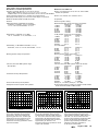
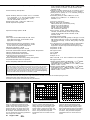
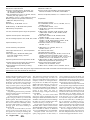
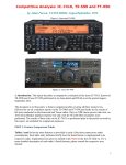
Product Review Column from QST Magazine
August 1998
Yaesu FT-847 HF/VHF/UHF Transceiver
ICOM IC-T8A Multiband Hand-held Transceiver
Copyright © 1998 by the American Radio Relay League Inc. All rights reserved.
Product Review
Edited by Rick Lindquist, N1RL• Senior Assistant Technical Editor
Yaesu FT-847 HF/VHF/UHF Transceiver
Reviewed by Steve Ford, WB8IMY
QST Managing Editor
In the high-stakes poker game that characterizes the Amateur Radio industry today, Yaesu has significantly raised the ante
with the debut of its FT-847 HF/VHF/UHF
transceiver. For the first time in ham history we have a single radio that covers all
HF bands plus the three most active VHF/
UHF bands right out of the box! (Yaesu’s
earlier FT-767 offered similar capabilities
but required optional modules—Ed.)
This everything-in-one-box trend was
pioneered several years ago when ICOM
combined HF, 6 and 2 meters in a single rig
and created the IC-706. It was an instant
hit. Other manufacturers quickly followed
suit with HF radios that also included
6 meters and, in some cases, 2 meters. In rolling out the FT-847 Yaesu has trumped the
competition by adding 70 cm and satellite
capability. The FT-847 certainly represents
the state of the art in one-stop transceiver
shopping. But how does this revolutionary
rig really measure up? Let’s take a look.
Styling, Ports and Controls
The FT-847’s styling departs from the
traditional “shoebox” look. This transceiver
is sleek and dark with a low vertical profile.
The ’847 is compact and fits easily on any
desktop. It is a bit bulky for installation in
smaller automobiles, but it should fit well in
most sports utility vehicles and intermediate-sized cars. Unlike some mobile-friendly
radios, however, the ’847’s front panel does
not detach for remote mounting.
An assortment of buttons and knobs
crowd the front panel, but even my thick
fingers could navigate this ergonomic forest with little difficulty. The FT-847 display is extremely bright and crisp (you can
adjust the brightness through eight different levels). The blue-on-white characters
are easy on the eyes, regardless of the viewing angle. For the visually impaired Yaesu
has thoughtfully added the ability to verbally announce the frequency display
through the use of the optional FVS-1A
voice unit. To activate the FVS-1A, you
simply press the front-panel VOICE button.
Metering is incorporated into the left-hand
side of the LCD display. There is an
S meter, an FM discriminator meter, and a
real RF power output meter calibrated in watts
(not just a relative output meter). There is no
SWR metering, something that’s become
practically a staple in modern radios, but there
is a HI SWR indicator on the display. When
using the FT-847 with the optional ATAS64
August 1998
100 multiband mobile antenna system, the
meter scale shows reflected power instead.
The front panel controls include the
usual suspects, such as concentric AF and
RF gain knobs, RF power output, microphone level, receiver incremental tuning
(labeled CLAR for “clarifier”), IF shift, and
a numeric keypad. You’ll also find a control
to adjust the CW keyer speed (a welcome
improvement over rigs that hide this function in a menu system) and a set of concentric knobs and companion buttons for the
DSP functions.
The primary VFO knob is dead center on
the panel. Concentric with this knob is the
Shuttle Jog ring. You can make enormous
frequency changes very quickly by grasping the ring and gently rocking it clockwise
or counterclockwise. Think of it as a frequency “fast forward/reverse” control. At
first, it seemed awkward, but I soon mastered the necessary movements. From that
point onward, Shuttle Jog was the only way
to fly! The MEM/VFO CH knob also permits
quick frequency excursions according to
the step size selected.
One front-panel control that users remarked about was the single MENU button.
This provides simple, quick access to the
radio’s additional features.
BOTTOM LINE
Yaesu may have one-upped the
competition with the FT-847. Here’s an
all-in-one HF through UHF transceiver
package that couples lots of features
and reasonable performance across
the board with a price tag that many
hams will find hard to resist.
You’ll find the headphone jack on the
front panel, where it should be. The headphone jack requires a 1 /4 -inch plug.
On the ’847’s rear panel you’ll find no
fewer than four antenna jacks: HF, 6 meters,
2 meters and 70 centimeters. (The 70-cm
jack is a female N connector; the others are
SO-239s.) The menu lets you redirect
6-meter signals (transmit and receive)
through the HF antenna port, eliminating the
need for an external diplexer when using a
combined HF/6-meter antenna.
The FT-847 does not have an internal
automatic antenna tuner, even as an option.
Yaesu does offer the FC-20 external autotuner, however, for HF through 6 meters.
Surrounded by the antenna jacks on the
rear panel is a small cooling fan. There’s a
second cooling fan near the front panel, and
the two fans work in concert—what Yaesu
calls a “push-pull” cooling system. These
fans run continuously. Some reviewers
complained that the fans were noisy, saying that it reminded them of a loud fan in a
computer power supply. Others didn’t seem
to mind the high-pitched whine at all. Like
everything else, it boils down to a matter of
personal preference.
Among the other rear-panel jacks are
separate ports (these are mini-DIN style
jacks) for VHF/UHF packet (1200 or 9600
baud) and HF digital modes. The HF DATA
IN/OUT data jack does double duty as the
fixed-level audio output. The computercontrol port (CAT) is represented by a 9pin DB-9 jack. You do not need an external
interface to connect the FT-847 to your
computer, but you must use a null-modem
cable rather than a straight serial cable.
Convenient as this CAT function is, there
is a substantial fly in the ointment. See the
Table 1
Yaesu FT-847, serial number 8C020205
Manufacturer’s Claimed Specifications
Measured in the ARRL Lab
Frequency coverage: Receive, 0.1-30, 36-76, 108-174,
Receive, 0.5-32(see text), 35-76, 108-174, 420-512 MHz;
420-512 MHz; transmit,1.8-2, 3.5-4, 7-7.3, 10.1-10.15, 14-14.35,
transmit, as specified.
18.068-18.168, 21-21.45, 24.89-24.99, 28-29.7, 50-54, 144-148, 420-450 MHz.
Power requirement: Receive, 2 A; transmit, 22 A (100W output).
Receive, 2 A; transmit, 20 A. Tested at 13.8 V.
Size (height, width, depth): 3.4×10.2×10.6 inches; weight, 14.4 pounds.
Modes of operation: SSB, CW, AM, FM, AFSK.
As specified.
Receiver
SSB/CW sensitivity, bandwidth not specified,
10 dB S/N: 1.8-30 MHz, <0.25 µV; 50-54 MHz,
<0.2 µV; 144-148, 420-450 MHz, <0.13 µV.
Receiver Dynamic Testing
Minimum discernible signal (noise floor), 500 Hz filter:
Preamp off
Preamp on
1.0 MHz
–129 dBm
–134 dBm
3.5 MHz
–131 dBm
–137 dBm
14 MHz
–131 dBm
–136 dBm
50 MHz
–134 dBm
–140 dBm
144 MHz
–140 dBm
–142 dBm
432 MHz
–139 dBm
–141 dBm
10 dB (S+N)/N, 1-kHz tone, 30% modulation:
Preamp off
Preamp on
1.0 MHz
2.4 µV
1.2 µV
3.8 MHz
1.9 µV
0.8 µV
50 MHz
1.0 µV
0.6 µV
120 MHz
1.3 µV
0.5 µV
144 MHz
0.6 µV
0.4 µV
432 MHz
0.8 µV
0.5 µV
For 12 dB SINAD:
Preamp off
Preamp on
29 MHz
0.7 µV
0.3 µV
52 MHz
0.4 µV
0.2 µV
146 MHz
0.2 µV
0.2 µV
440 MHz
0.3 µV
0.2 µV
Blocking dynamic range, 500 Hz filter:
Preamp off
Preamp on
3.5 MHz
114 dB
109 dB
14 MHz
114 dB*
109 dB*
50 MHz
114 dB*
112 dB*
144 MHz
103 dB*
96 dB*
432 MHz
105 dB*
98 dB*
Two-tone, third-order IMD dynamic range, 500 Hz filter:
Preamp off
Preamp on
3.5 MHz
92 dB
90 dB
14 MHz
95 dB
89 dB
50 MHz
89 dB
90 dB
144 MHz
88 dB
84 dB
432 MHz
85 dB
83 dB
Preamp off
Preamp on
3.5 MHz
+6.1 dBm
–0.5 dBm
14 MHz
+12 dBm
–0.7 dBm
50 MHz
+0.9 dBm
–5.5 dBm
144 MHz
–11 dBm
–19 dBm
432 MHz
+2.6 dBm
–6.5 dBm
Preamp off, +12.4 dBm; preamp on, +14.7 dBm.
20 kHz channel spacing, preamp on: 29 MHz, 82 dB; 52 MHz,
80 dB; 146 MHz, 69 dB; 440 MHz, 68 dB.
AM sensitivity, 10 dB S/N: 0.5-1.8 MHz,
<20 µV; 1.8-30 MHz, <2 µV; 50-54 MHz, <1 µV.
FM sensitivity, 12 dB SINAD: 28-30 MHz, <0.5 µV;
50-54 MHz, <0.25 µV; 144-148, 420-450 MHz, <0.2 µV.
Blocking dynamic range: Not specified.
Two-tone, third-order IMD dynamic range:
Not specified.
Third-order intercept: Not specified.
Second-order intercept: Not specified.
FM adjacent channel rejection: Not specified.
0
0
0
Reference Level: 0 dB PEP
Reference Level: 0 dBc
Reference Level: 0 dB PEP
–10
–10
–10
–20
–20
–20
–30
–30
–30
–40
–40
–40
–50
–50
–50
–60
–60
–60
–70
–70
–70
–80
0
–80
–10
20
40
60
80 100 120 140
Frequency (MHz)
160
180
200
Figure 1—Worst-case spectral display of
the FT-847 transmitter during spectral
purity testing. Note the multiple spurs
appearing just below the –40 dBc legal
threshold for spurious emissions at full
output power on this frequency. The
transceiver was being operated at 100 W
output at 28.0 MHz.
–8
–6
–4
–2
0
2
4
Frequency Offset (kHz)
6
8
10
Figure 2—Worst-case spectral display of
the FT-847 transmitter during two-tone
intermodulation distortion (IMD) testing on
HF. The worse-case third-order product is
approximately 28 dB below PEP output,
and the worse-case fifth-order product is
approximately 51 dB down. The
transceiver was being operated at 100 W
output at 28.350 MHz.
–80
–10
–8
–6
–4
–2
0
2
4
Frequency Offset (kHz)
6
8
10
Figure 3—Worst-case spectral display of
the FT-847 transmitter during two-tone
intermodulation distortion (IMD) testing on
VHF/UHF. The worse-case third-order
product is approximately 28 dB below PEP
output, and the worse-case fifth-order
product is approximately 46 dB down. The
transceiver was being operated at
50 W output at 432.2 MHz.
August 1998
65
FM two-tone, third-order IMD dynamic range: Not specified.
S-meter sensitivity: Not specified.
Squelch sensitivity: SSB, 0.5-1.8 MHz, <20 µV; 1.8-30 MHz,
<2 µV; 50-54 MHz, <1 µV; 144-148, 420-450 MHz, <0.5 µV;
FM, 28-30 MHz, <0.25 µV; 50-54 MHz, <0.2 µV;
144-148, 420-450 MHz, <0.16 µV.
Receiver audio output: 1.5 W at 10% THD into 8 Ω.
IF/audio response: Not specified.
Spurious and image rejection: 60 dB.
Transmitter
Power output: HF & 50 MHz: SSB, CW, FM, 100 W
(high); AM, 25 W (high); 144 & 420 MHz, 50 W
(high); AM, 12.5 W (high).
Spurious-signal and harmonic suppression: ≥40 dB
on HF for harmonics, ≥50 dB for spurious; ≥60 dB
on VHF & UHF for harmonics and spurious.
SSB carrier suppression: ≥40 dB.
Undesired sideband suppression: ≥40 dB.
Third-order intermodulation distortion (IMD) products: Not specified.
CW keyer speed range: Not specified.
CW keying characteristics: Not specified.
Transmit-receive turn-around time (PTT release to
50% audio output): Not specified.
Receive-transmit turn-around time (tx delay): Not specified.
Composite transmitted noise: Not specified.
Bit-error rate (BER), 9600-baud: Not specified.
Expanded Product Review Report Available
The ARRL Laboratory offers a detailed test result report on the Yaesu FT-847 that gives indepth, technical data on the transceiver’s performance, outlines our test methods, and
helps you to interpret the numbers and charts. The report even includes a summary of how
this radio stacks up with similar, previously tested units. Request the FT-847 Test Result
Report from the ARRL Technical Department, 860-594-0278; e-mail [email protected].
It’s $7.50 for ARRL members and $12.50 for nonmembers, postpaid.
20 kHz channel spacing, preamp on: 29 MHz, 77 dB; 52 MHz,
76 dB; 146 MHz, 69 dB*; 440 MHz, 68 dB*; 10 MHz channel
spacing, preamp on: 52 MHz, 107 dB; 146 MHz, 89 dB;
440 MHz, 82 dB.
S9 signal at 14.2 MHz: preamp off, 65 µV; preamp on, 20 µV;
52 MHz, preamp off, 45 µV; preamp on, 15 µV; 146 MHz,
preamp off, 22 µV; preamp on, 9.1 µV; 432 MHz, preamp off,
39 µV; preamp on, 12 µV.
At threshold, preamp on: SSB, 14 MHz, 0.5 µV; FM,
29 MHz, 0.2 µV; 52 MHz, 0.1 µV; 146 MHz, 0.1 µV;
440 MHz, 0.1 µV.
2.4 W at 10% THD into 8 Ω.
Range at –6dB points, (bandwidth):
CW-N (500 Hz filter): 121-902 Hz (781 Hz);
CW-W: 130- 2135 Hz (2005 Hz);
USB-W: 138-3103 Hz (2965 Hz);
LSB-W: 160-3143 Hz (2983 Hz);
AM: 110-2930 Hz (2820 Hz).
First IF rejection, 14 MHz, 122 dB; 50 MHz, 54 dB;
144 MHz, 123 dB; 432 MHz, 84 dB; image rejection,
14 MHz, 95 dB; 50 MHz, 96 dB; 144 MHz, 97 dB;
432 MHz, 55 dB.
Transmitter Dynamic Testing
HF & 50 MHz: CW, SSB, FM, typically 107 W high, 1.5 W low;
AM, typically 28 W high, 3 W low; 144 & 432 MHz: CW, SSB,
FM, typically 50 W high, 1.5 W low; AM, typically 13 W high,
1.5 W low.
HF, 41 dB (see Figure 1); 50 MHz, 63 dB; 144 and 432 MHz,
70 dB. Meets FCC requirements for spectral purity for
equipment in its power output class and frequency range.
As specified. >50 dB.
As specified. >55 dB.
See Figures 2 and 3.
10 to 41 WPM.
See Figure 4.
S9 signal, 12 ms.
SSB, 12 ms; FM, 11 ms. Unit is suitable for use on AMTOR.
See Figures 5 and 6.
146 MHz: Receiver: BER at 12-dB SINAD, 1.1×10⁻³; BER at
16 dB SINAD, 4.0×10⁻⁵; BER at –50 dBm, <1.0×10⁻⁵;
transmitter: BER at 12-dB SINAD, 2.1×10⁻⁴; BER at 12-dB
SINAD + 30 dB, <1.0×10⁻⁵.
440 MHz: Receiver: BER at 12-dB SINAD, 1.1×10⁻³; BER at
16 dB SINAD, 4.0×10⁻⁵; BER at –50 dBm, <1.0×10⁻⁵;
transmitter: BER at 12-dB SINAD, 8.9×10⁻⁴; BER at 12-dB
SINAD + 30 dB, <1.0×10⁻⁵.
Note: Unless otherwise noted, all dynamic range measurements are taken at the ARRL Lab standard spacing of 20 kHz.
*Measurement was noise-limited at the value indicated.
Third-order intercept points were determined using S5 reference.
–60
–70
–60
Reference Level: - 60 dBc/Hz
Vertical Scale: dBc/Hz
–70
–80
Figure 4—CW keying waveform for the
FT-847 showing the first two dits in semibreak-in mode. The equivalent keying
speed is 60 wpm. The upper trace is the
actual key closure; the lower trace is the
RF envelope. Horizontal divisions are 10
ms. The transceiver was being operated at
100 W output at 14.2 MHz.
66
August 1998
–80
–90
–90
–100
–100
–110
–110
–120
–120
–130
–130
–140
2
Reference Level: - 60 dBc/Hz
Vertical Scale: dBc/Hz
4
6
8
10
12
14
16
18
20
Frequency Sweep: 2 to 22 kHz from Carrier
22
Figure 5—Worst-case tested spectral
display of the FT-847 transmitter output
during composite-noise testing on HF.
Power output is 100 W at 3.5 MHz. The
carrier, off the left edge of the plot, is not
shown. This plot shows composite
transmitted noise 2 to 22 kHz from the
carrier.
–140
2
4
6
8
10
12
14
16
18
20
Frequency Sweep: 2 to 22 kHz from Carrier
22
Figure 6—Worst-case tested spectral
display of the FT-847 transmitter output
during composite-noise testing on VHF/
UHF. Power output is 50 W at 432.2 MHz.
The carrier, off the left edge of the plot, is
not shown. This plot shows composite
transmitted noise 2 to 22 kHz from the
carrier.
sidebar “The CAT’s Meow?”
The rear panel also offers an ALC port,
a PTT jack (in case you want to use a foot
switch to key the rig), and an external
speaker jack. Speaking of speakers, you’ll
find one on the top panel. The audio is clear
and smooth—among the best audio we’ve
heard from a transceiver in a long time. The
AF GAIN control acted a bit strangely,
though. On all three units we looked at,
there was no audio at all for the first quarter
turn, at which point it sprang to life. Yaesu
says it has addressed this problem in current production.
Last but not least on the rear apron is the
dc power connector (you must provide your
own ac supply). Yaesu’s dc power cord,
comprised of four, separate wires, did not
make a favorable impression. At the very
least, the whole assembly should have been
secured with cable ties.
It’s possible to install up to three optional Collins mechanical filters in the
FT-847. A 500-Hz CW filter, the YF-115C,
can be installed in the 455 kHz second IF.
We purchased the optional CW filter. Since
the radio is capable of full-duplex satellite
operation, Yaesu offers optional SSB
Collins mechanical filters for both receive
and transmit to replace the stock ceramic
filters in the second IF. Yaesu says the
transmit filter should yield flatter, more
natural-sounding audio. We did not install
nor test these optional SSB filters, however.
HF Performance
The FT-847 generates 100 W output on
160 through 10 meters in the CW, SSB and
FM modes, and 25 W on AM. In the HF
range, it also receives continuously from
100 kHz to 30 MHz, but in the ARRL Lab,
we found that useful sensitivity actually
begins around 500 kHz or so.
In the “nice touch” department, we’d
like to note that the FT-847 is the first
amateur transceiver we know of that includes provisions to transmit on the Alaska
emergency communications frequency of
5167.5 kHz.
Operation is straightforward and intuitive. I had it on the air the first time in under
a minute without referring to the manual.
You simply plug in the hand-held microphone (supplied), push the POWER button,
push the button for your favorite mode
(SSB, FM, AM or CW), turn up the microphone and RF gain controls as necessary,
select your frequency, and you’re all set!
Audio reports on the voice modes were
excellent, even when running the speech
processor. By pressing the MONI button you
can listen to melodious sound of your own
voice in your headphones. This is a neat
feature that you usually find only on more
expensive radios. (When you’re using too
much speech compression, you’ll know
right away!) The missing element, puzzling
as it may seem, is the voice-activated switch
or VOX. Not all operators will bemoan the
lack of a VOX, but DXers and contesters
certainly will. (On the other hand, the ’847
does have a MOX—manually operated
switch—which is convenient when testing
or making adjustments.) Yaesu says it considered including VOX but decided against
it because of the FT-847’s primary application as a satellite radio.
The built-in electronic keyer acquitted
itself well on CW, although the keyer speed
shifts quite a bit with just minor movements
of the front-panel control. This makes it
difficult to set the speed exactly where you
want it. The keyer does not have any message buffers (memories). The ’847 doesn’t
support full break-in either. You can set the
T/R delay to as little as 10 ms, but that’s as
close as you’ll get to QSK, and then you’ll
have to put up with the clattering of the
T/R relay (the maximum delay is 300 ms).
On CW, the MONI button enables or disables the sidetone.
One terrific feature for CW fans is the
spotting function. Even newbies can use this
tool to easily and accurately zero beat with
the stations they intend to call. It’s sometimes amazing how many CW QSOs you’ll
still find where stations are sometimes hundreds of Hertz apart because of faulty zero
beating. This can be annoying, especially if
there are more than two stations on frequency. It also means the QSO is taking up
more room on the band than it needs to.
On RTTY and PACTOR I, the FT-847
turned in a good performance. Transmit/receive turnaround was more than sufficient
for excellent long-distance PACTOR operating. The ’847 does not offer an FSK mode
with narrow filters; this is strictly an AFSK
rig. But with the DSP filters you can narrow
the audio bandwidth considerably. This
isn’t as desirable as having a narrow filter in
the IF, but it is acceptable for all but the
most crowded conditions. The FT-847
manual strongly advises against running full
output in the RTTY mode. In fact, Yaesu
recommends that you throttle the output
down to about 50 W when operating RTTY.
The FT-847’s overall HF reception is
good, but not stellar. For the sake of comparison, the dynamic range numbers (both
blocking and two-tone, third order IMD) of
Yaesu’s FT-920 were slightly better on HF
(see “Product Review,” QST, Oct 1997).
The transceiver is sensitive enough for casual operating, and its selectivity is adequate
in that respect as well. Under crowded band
conditions (during a contest, for example),
the ’847’s HF receiver showed its weakness.
Nearby signals hammered the AGC, and it
soon became obvious that ’847’s dynamic
range characteristics were not up to the task.
Then again, Yaesu isn’t marketing the ’847
as a contest radio. If it were a high-performance HF contest rig, you’d also expect to
shell out quite a few more dollars for the
pleasure of owning it.
The FT-847’s transmit IMD performance on HF (see Figure 2) was quite good
on most bands. The worst case was 10
meters, one of only two HF bands where
the third-order IMD products poked above
–30 dB (the other was 12 meters). Especially noteworthy, however, was the fact
that third-order IMD products were down
by around 40 dB on some lower bands, and
fifth and higher-order products were sub-
stantially down across the HF range—in
all cases more than 40 dB and approaching
50 dB on 40 and 20 meters!
Bird Watching
One irritant our reviewers noticed was a
proliferation of internally generated signals—“birdies”—on several HF bands.
Birdies were audible even with the antenna
disconnected. Fifteen meters was the worst.
We suspected a problem with the particular
’847 we had purchased, so we bought another radio. No such luck. The birdies were
present on the second rig as well, although
they were not as prominent as they were on
the first unit, and they were on different
frequencies. In addition, we’d noted that
both radios, while spectrally legal, did not
meet Yaesu’s –50 dB specification for spurious and harmonic emissions and had numerous spurs (see Figure 1). The consensus was that we definitely had a problem,
but its nature was not entirely clear.
We’d bought our two FT-847s from different dealers and at slightly different
times. Nonetheless, judging from the close
serial numbers, both radios appeared to be
from the very same production run—probably made on the same day and pretty early
in the game to boot. To get another perspective, we borrowed yet another FT-847
from a dealer. This one was from a more
recent production run, and it harbored
hardly any birdies.
We contacted Yaesu, providing the
manufacturer with spectral purity charts
and outlining our experience with the receiver birdies. Yaesu determined that the
birdies resulted from poor soldering flux
removal on the DSP board (go figure).
Removing the flux residue scattered the
birdies.
The spectral purity issues—not at all
related to the birdies—turned out to be of
greater concern to Yaesu and led to considerable head scratching on both sides of the
Pacific. Yaesu finally determined that the
spurs were related to “variations in the
interstage drive levels” and said that “slight
changes to three components” brought our
unit back into specification. We did not get
our FT-847 back from Yaesu in time to
verify this before our review went to press,
however. Yaesu says that, while this was
not a widespread problem in FT-847 production, customers who experience out-ofspec spur levels may return their units to
Yaesu for “warranty relief, per the terms of
our one-year limited warranty.” If the last
FT-847 we examined is any criterion, birdies and spectral purity should not be an issue in current production.
DSP
On the plus side, the ’847’s DSP functions are outstanding. The automatic
notcher is especially impressive, but it reacts more slowly than many external boxes,
taking up to a half-second to vanquish offending carriers. The autonotch even
worked on the internal birdies that we’d
noticed, but it won’t help you on CW because the notch will zap the signals you want
August 1998
67
as well as the ones you don’t! The NR (noise
reduction) function eliminates much of the
tiresome background hash. It does so without introducing so much of the hollow processing echo often heard in other DSP noise
reduction filters. One gripe: Yaesu put the
NR level on the menu instead of making it a
front-panel control. Some ops felt that adjustment would get more use than, say, mike
gain, which is on the front panel.
By manipulating the high/low-cut
bandpass filter controls, you can tailor the
DSP filtering performance to meet the precise need of the moment. Very nice! The
only problem is that when you’re in CW,
the DSP shifts into a mode that does not
permit adjustment of the dual bandpass!
The DSP filtering does a creditable job of
simulating a narrow passband—even without the optional Collins mechanical filters—but some users said they wanted the
ability to adjust the bandwidth manually
too. It’s worth noting that the non-DSP
noise blanker did a fine job on impulse
noise. This is particularly important for
mobile operating.
IF shift is a genuine asset in the FT-847,
although most ops would welcome a center
detent for the control. The AGC can be
toggled from fast to slow at the press of a
button. The clarifier (RIT) is also pushbutton activated and adjusted with a knob
immediately beneath, but it takes a bit of
cranking to move very far. When you tweak
the clarifier the main frequency display reflects the change. This means you can’t tell
right away where you started out, and
there’s no way to clear the RIT offset with
a button press. The ’847 does not offer XIT
(transmit incremental tuning).
Like most modern transceivers, the ’847
provides dual VFOs and copious memories
(about 80 in all). What the ’847 adds to this
milieu, however, is extremely smooth and
precise tuning. You can tune easily in 1-Hz
steps; that’s the default minimum. You can
even tune in as little as 0.1 Hz increments
if you desire!
VHF/UHF Performance
On SSB, CW and FM, the FT-847 cranks
out 100 W on 6 meters and an impressive
50 W on 2 meters and 70 centimeters. Receive coverage spans 36 to 76 MHz (great
for monitoring European TV to check the
MUF and to listen on the UK 4-meter band),
108 to 178 MHz, and 420 to 512 MHz. In the
ARRL Lab, we found there was poor sensitivity on some frequencies outside the ham
bands—36 to 37 MHz, for example.
On 6 meters, 100 W is more than enough
power for all but the most challenging
work. On 2 meters and 70 cm, 50 W is adequate for local/regional communication
and for most satellite work, depending on
the type and location of your antennas. In
both cases, the output is plenty to drive an
external amplifier. After using the FT-847
during the June VHF QSO Party, one user
wished for the ability to preset power levels on different bands so he’d always have
the right amplifier drive level when switching from, say, 6 meters to 2 meters.
68
August 1998
The CAT’s Meow?
The Yaesu FT-847 offers the timehonored CAT function—computer
aided transceiver. Simply put, it is a port
that allows your computer to control
your radio. The CAT implementation in
the ’847 is especially handy because
no interfaces or level converters are
required. You just hook up your computer and you’re in business. The CAT
in the FT-847 has a problem, though,
and it isn’t related to fleas or hairballs.
The way the port is currently programmed, the communications path
between the ’847 and your computer is
essentially one-way—from your computer to the ’847. The computer can
send commands to the radio, but it can
get precious little information from the
radio. Contest and logging programs
could send commands for frequency
and mode changes, for example, but
could not poll the rig to determine the
frequency or mode the operator had
chosen. Remote-control software
would encounter the same problem.
This is a serious shortcoming but,
fortunately, Yaesu says it is updating
this firmware to read back operating frequency and mode. It is hoped that the
revised CAT port program will be available as a ROM upgrade for current
FT-847 owners.
On FM the FT-847 is a full-featured radio par excellence. You can store all of your
favorite repeater pairs and simplex frequencies in the abundant memory channels along
with offsets and CTCSS tones. If you really
want to get into paging, the ’847 grants your
wish with a versatile DCS (digital coded
squelch) function. The FT-847 even has
crossband split capability, although this is a
one-way “simplex” feature. That is, you can
repeat from 2 meters to 70 cm, for example,
but the rig will not automatically relay the
response from 70 cm back to 2 meters (semiduplex). To get full duplex, you have to be
in Satellite mode. More on that later.
The scanning functions are not limited
to VHF/UHF. These include programmable
band scans and memory channel scans. The
Smart Search will scan for signals and
place them into memory automatically, a
really handy feature if you take the FT-847
on the road. And, of course, there is the
ubiquitous priority channel scan. This can
be put to use to make up for the lack of a
dual watch capability, so you can have the
radio keep an ear on, say, a calling frequency on one band while you operate on
another frequency or band altogether.
Packet is more than an afterthought on
the FT-847. Yaesu engineers obviously paid
careful attention to tailoring the transmit
and receive response for optimum 1200 and
9600-baud performance. All you have to do
is hook up your TNC to the rear panel jack,
then select 1200 or 9600 baud via the menu.
When it comes to so-called “weak-sig-
nal” SSB and CW operating, the receiver
characteristics to a degree mirrored what
we had experienced on HF. How individual
users view this performance depends on
what they’re used to. In terms of VHF/UHF
preamp-on sensitivity, the FT-847, Yaesu’s
1990-vintage FT-736R, and ICOM’s
IC-821H are in the same ballpark (the
’847’s preamp adds 2 dB to 6 dB). But when
it comes to dynamic range (see Table 1),
the FT-847 is head-and-shoulders better
than its older sibling FT-736R, comparable
to the IC-821H on the two bands they have
in common (2 meters and 70 cm) and well
short of the Yaesu FT-920’s approximately
100 dB on 6 meters. That said, we want to
make it clear that we consider this level of
performance entirely acceptable for 90%
of the terrestrial VHF/UHF operating that
you’re likely to encounter.
You can add external preamps at the
antenna, which is always a good idea at
VHF and UHF. If you go this route, the
’847 can provide 12 V dc at the 2 meter and
70 cm antenna jacks. This option is accessible via the menu.
By the way, an important attribute for
weak signal VHF/UHFers wanting to operate portable or mobile is the frequency accuracy at various outside temperatures.
This is particularly important at 70 cm. The
FT-847’s basic accuracy is 2 ppm between
0 and 40° C (32 to 104° F). At 440 MHz,
this amounts to a nearly 1 kHz error, and
the accuracy at even colder or warmer extremes is 5 ppm. That’s a whopping 2 kHz
error at 440 MHz! Yaesu says the transceiver actually may outperform these specs
“by a considerable margin,” but this is especially noteworthy since Yaesu does not
offer a temperature-compensated crystal
oscillator (TCXO) option.
Contests will present the greatest challenge
for the FT-847 at VHF and UHF. We used the
rig during the ARRL Spring Sprints—not a
terribly active string of contests—and found
that the ’847 sometimes didn’t tolerate adjacent signals very well (we observed both
“crackling” and AGC pumping).
This handicap would become serious
during popular rough-and-tumble slugfests
such as the VHF QSO Parties. But if you’re
not a serious contester, this aspect of the
FT-847 is of little importance.
Transmit IMD performance (see Figure
4) on VHF and UHF was quite acceptable,
with third-order products hovering around
–30 dB and fifth and higher-order products
at or approaching –50 dB on 2 meters and
70 cm!
Satellite Operation
As its marketing suggests, the FT-847’s
strong suit is as a satellite radio. It seems to
be Yaesu’s answer to those satellite operators who’ve eagerly awaited a successor to
their legendary FT-736 transceiver. It is
also a substantial shot fired across the bow
of the popular ICOM IC-821H. One op who
owns a ’736 found the ’847 simpler to use.
When you place the ’847 in the SAT
(satellite) mode, it becomes a very different kind of radio. Suddenly you have full-
duplex crossband capability (the subband
frequency is displayed along with the
main band) as well as dual VFOs that can
be yoked together for easy frequency
tracking—in either direction. For example, on satellites that have inverting
transponders, such as Fuji-OSCARs 20,
29 and the upcoming Phase 3D, an increase
in the uplink frequency results in a decrease in the downlink frequency. (The
reverse is also true.) With a properly configured FT-847, an upward tweak of the
uplink (transmit) VFO automatically
shifts the downlink (receive) VFO by
the same amount. This removes much of
the confusion from inverted-transponder
operating.
On the air, I had no difficulty hearing
and working Fuji-OSCAR 20 on SSB.
Switching to FM, I worked the AO-27 FM
repeater satellite easily. For several minutes during the pass I enjoyed full-quieting
signals. Thanks to the FT-847’s flexible
crossband capability, I was even able to
work RS-15 on Mode A (2 meters up, 10
meters down). All of these contacts were
made using omnidirectional antennas. (For
those who may be wondering, the FT-847
is not able to work its full-duplex
crossband magic between 15 meters and
10 meters for RS-12 on Mode K! You can,
however, store a 10-meter and a 15-meter
frequency in memory for simplex
crossband operation.) Another Mode A
user reported some downlink signal degradation when using the FT-847 in SAT
mode that he did not experience when using his FT-736R as a transmitter and the
FT-847 as the receiver. Mode B, however,
was “crystal clear.”
The FT-847 is a very strong competitor
to the IC-821H. Not only does the ’847
provide most of the same features, it
includes 6 meters and HF. For a few
hundred dollars more on the price tag, the
FT-847 is going to look very attractive to
those in the satellite community. The only
item I would add to my FT-847 wish list is
the ability to reduce output below 1 W
for use with external transverters. Even
without a “transverter port” the ’847 will
probably make a worthy platform for those
who want to step up to microwave operating when Phase 3D finally reaches orbit—
as long as you can “pad down” the output
to acceptable levels.
Conclusion
The Yaesu FT-847 definitely breaks
new ground in the ham transceiver marketplace. Its “hits” are numerous and include
the superb user manual. This manual is one
of the best we’ve seen in many years. It
even includes tutorials on using the ’847
for high-speed CW meteor scatter and
moonbounce! The misses, such as the receiver birdies in the first two units we
looked at, CAT programming problems,
and lackluster selectivity, are mild annoyances. For the casual operator who wants
everything in one stylish box, you can’t go
wrong with the FT-847.
Our thanks to Rick Lindquist, N1RL;
Peter Budnik, KB1HY; Emil Pocock,
W3EP; and Mike Tracy, KC1EX, and Ed
Hare, W1RFI, of the ARRL Lab for their
contributions to this review.
Manufacturer: Yaesu USA, 17210
Edwards Rd, Cerritos, CA 90703, tel 562404-2700; fax 562-404-1210. Manufacturer’s suggested list prices: FT-847,
$2399; ATAS-100 mobile antenna system,
$349; FVS-1A voice unit, $43; optional
Collins mechanical narrow filters, $173;
FC-20 external autotuner, $299.
ICOM IC-T8A Multiband Hand-held Transceiver
Reviewed by Rick Lindquist, N1RL
Senior Assistant Technical Editor
That funny noise you began hearing early
this year was the collective groans of the
competition as ICOM’s IC-T8A began
showing up at retailers. ICOM—the same
company that blew everyone away a few
years ago with the now seemingly ubiquitous IC-706 (and followed it up last fall with
the IC-706MkII)—now has another first.
It’s the world’s smallest triband hand-held
that includes 6 meters (Standard’s C-568A,
for example, covers 2 meters, 70 cm, and
23 cm). So, you could say the IC-T8A is
without peer—so far at least.
For this particular review, we’re making
a bit of an exception for an exceptional
product. Typically, we review H-Ts and
VHF/UHF mobiles in groups of peer products—dual-band hand-helds, 2-meter mobiles, etc. ICOM debuted its three-band
IC-T8A just weeks shy of the deadline
to include it in our last review of dual-band
hand-helds (see “Product Review,” QST,
April 1998)—which we would have had to
retitle to “multiband,” in any event. Since
interest has been pretty high in this unit,
we’re singling it out here so our readers
won’t have to wait until the next comparison review.
Besides being a “first,” the IC-T8A is
exceptional because it offers a great deal at
an economical price—just a bit more than
ICOM’s own IC-T7A or IC-W32A (see
“Product Review,” QST, July 1997) dualbanders. In addition to 6 and 2 meters plus
70 cm, you get gobs of receiver coverage
outside the ham bands—including the aircraft, 150, and 450-MHz public safety bands
plus (as if you’d even expect more) FM and
TV broadcast channels. There are some gaps,
however. More on that later.
The T8A is the first H-T we’ve seen
that includes an NiMH battery pack as standard equipment. The clamshell-style 9.6 V,
680 mAh NiMH battery pack comprises
about one-half of the unit’s depth. Several
users commented that the battery does not
snap snugly onto the transceiver’s back.
With a PC, an optional cloning cable,
and optional model CS-T8 cloning software, you can assign memory names of up
to four characters. The current software is
DOS only. As this review was going to
press, we learned that ICOM soon will debut a Windows version, CSW-HH4, estimated to sell for around $50. Another optional cloning cable lets you copy the
memories of one T8A into another.
The first thing a lot of hams like to do
when they try out an H-T is to see how it fits
in their palm—and maybe to heft it a bit—
to get a feel for what it would be like to use
it on a regular basis. The T8A fits nicely
into either palm, depending on whether you
prefer to actuate the PTT button with your
thumb or your forefinger. Any larger and it
would not be nearly as, well, handy.
It has a rugged, water-resistant case, and
the unit conforms to MilSpec shock and vibration standards. The keypad buttons are slightly
recessed to avoid accidental activation.
The display features 1/ 4 -inch tall letters.
Some might wish for the display to be a bit
larger and bolder, but it’s easy to read under typical lighting conditions, and you can
set one of two contrast levels. The unit offers backlighting for nighttime viewing of
the display (but not of the keypad buttons).
The “auto” lamp setting illuminates the
display every time you press a button (the
other settings are “on” and “off”).
Gone are the days when a couple of concentric rotary controls adorn the top of every
H-T. The IC-T8A sports a single rotary control, the multifunction DIAL knob. This is
used for tuning, selecting user-settable menu
functions or memories, and changing scan
direction among other things. All other controls are pushbuttons, including the VOLume
and squelch (SQL) controls. Radio purists
may decry the fact that the T8A uses buttons
to adjust the volume (a trend pioneered a few
years ago by Alinco and now becoming
much more common), but no one found it
inconvenient. You get a graphic display of
the relative volume level as you adjust—a
bit like the remote volume adjustment on
many modern TV sets.
The IC-T8A has an automatic squelch,
but you also can select one of eight
“manual” squelch levels or open (ie, no)
squelch. Pushing and holding the SQL button opens the squelch, too. The SQL button
and the PWR button are the smallest ones on
the unit and very close together—in the
lower and upper lefthand corners of the
display window. Their location makes
these buttons very easy to locate, even in
the dark, but some users wished for bigger
buttons.
Overall, getting acquainted with the
IC-T8A is pretty painless, especially if
you’re familiar with other recent-vintage
ICOM gear. Even if you’re not, the Instruction Manual is quite helpful, and especially
the Panel Description and Basic Operation
August 1998
69
Table 2—ICOM IC-T8A, serial number 1479
Manufacturer’s Specifications
Frequency coverage: Receive, 50-54 MHz, 118174 MHz, 400-470 MHz; transmit, 50-54 MHz,
144-148 MHz, 440-450 MHz
Power requirements: 4.5-16 V dc. Receive, 250 mA;
transmit, (max, high power), 1.8 A.
Size (HWD): 4.2×2.3×1.1 inches; weight 9.5 ounces.
Modes of operation: FM (transmit and receive),
WBFM and, AM (receive only).
Measured in ARRL Lab
Receive, 50-200, 400-1000 MHz, cell blocked (see text),
transmit, 50-54 MHz, 140-150 MHz, 430-450 MHz.
Receive, as specified; transmit, 1.4 A. Tested at 13.8 V dc.
As specified.
Receiver
FM sensitivity, 12 dB SINAD: 0.18 µV.
Receiver Dynamic Testing
For 12 dB SINAD: 52 MHz, 0.15 µV; 146 MHz, 0.16 µV;
440 MHz, 0.15 µV.
WFM sensitivity, 12 dB SINAD: Not specified.
For 12 dB SINAD: 98 MHz, 1.2 µV.
AM sensitivity: Not specified.
10 dB (S+N)/N, 1-kHz tone, 30% modulation;
120 MHz, 0.4 µV.
Two-tone, third-order dynamic range: Not specified.
52 MHz, 55 dB*; 146 MHz, 53 dB; 440 MHz, 52 dB;
10 MHz offset: 52 MHz, 70 dB; 146 MHz, 80 dB;
440 MHz, 66 dB.
Adjacent channel rejection: Not specified.
20 kHz offset: 52 MHz, 55 dB; 146 MHz, 60 dB;
440 MHz, 59 dB.
First IF and image rejection: VHF, 60 dB; UHF, 50 dB. IF rejection, 52 MHz, 62 dB; 146 MHz, 107 dB;
440 MHz, 119 dB. Image rejection, 52 MHz, 78 dB;
146 MHz, >143 dB; 440 MHz, 66 dB.
Squelch sensitivity: 0.18 µV.
At threshold, 52 MHz, 0.37 µV; 146 MHz, 0.16 µV;
440 MHz, 0.11 µV.
S-meter sensitivity: Not specified.
Audio output: 250 mW into 8Ω, THD not specified.
Transmitter
Power output (H/L): with BP-200 battery pack,
4.5 W; with external supply, VHF and
UHF, 5 W / 0.5 W.
Spurious signal and harmonic suppression: 60 dB.
52 MHz, S9=0.9 µV; 146 MHz, S9=1.3 µV;
440 MHz, S9=2.1 µV.
281 mW at 6% THD into 8Ω.
Transmitter Dynamic Testing
With BP-200 9.6 V battery pack: 52 MHz, 4.2 W / 0.6 W;
146 MHz, 4.6 W/ 0.5 W; 440 MHz, 3.2 W / 0.3 W
With external, 13.8 V dc supply: 52 MHz, 6.3 W / 0.6 W;
146 MHz, 5.7 W / 0.5 W; 440 MHz, 4.1 W / 0.3 W
52 MHz, 68 dB; 146 MHz, 70 dB; 440 MHz, 64 dB.
Meets FCC requirements for spectral purity.
Squelch off, S9 signal, 52 MHz, 120 ms;
146 MHz, 100 ms; 440 MHz, 60 ms.
52 MHz, 190 ms; 146 MHz, 120 ms; 440 MHz, 150 ms.
Transmit-receive turn-around time (PTT release to
50% of full audio output): Not specified.
Receive-transmit turn-aound time (“tx delay”):
Not specified.
Note: Unless otherwise noted, all dynamic range measurements were made at the ARRL Lab standard spacing of 20 kHz.
*Measurement was noise-limited at the value shown.
chapters. Like the T2A and T7A, the IC-T8A
includes ICOM’s guide function—which
acts like an on-line Help file. If you get
stuck, just wait and text will crawl across
the display to advise what you’re supposed
to do next. This can be very handy, especially if you don’t plan to carry the manual
around in your back pocket or pocketbook.
Users liked the “no-function-button” setup
for this radio.
Programming the T8A is easy, and some
users were able to figure it out without resorting to the manual.
On-the-air audio reports were uniformly
good, as long as you don’t try to close-talk
the microphone. The T8A includes topside
jacks to add a speaker-mike if you want.
The receive audio was remarkably robust
for such a small speaker. It sounded surprisingly good even when listening to
broadcast FM.
As you can see from Table 2, the T8A
receiver covers a lot of real estate, so you
can spend a lot of time just listening. Be
advised, however, that even though the
70
August 1998
T8A will tune to frequencies outside of its
specified coverage range, this does not
mean you will be able to hear anything. For
example, in FM-N, we found good sensitivity from 50 to 72 MHz, but it degraded
sharply above that point (eg, 5.4 µV at 76
MHz). The T8A is especially numb between 200 and 230 MHz. In the ARRL Lab,
we found no amount of signal could be received in this range, not even in
the millivolt range, so forget even listening
on 222 MHz.
By the way, we concur with ICOM
and advise against attempting the mod
making the rounds that enables transmit on
222 MHz. ICOM says this mod can damage
the radio. Of course, modifying the radio
voids the warranty, so why do it?
The unit does not tune between 230 and
300 MHz, and it’s deaf as a stone between
300 and 400 MHz. There’s another gap from
600 to 650 MHz. In FM-W, we measured
11.4 µV at 650 MHz and 3.4 µV at 800 MHz.
Reception modes were band or frequency-range specific. In other words, if
you’re listening to the aircraft band, you
can only listen in AM mode. If you’re in the
FM broadcast band, you can only listen in
WFM mode. You can independently set one
of nine tuning steps for each band.
How does the T8A stack up in the critical
areas of dynamic range and adjacent channel
rejection? Performance in some cases was
modest (see Table 2). We compared the
ARRL Lab numbers for 2 meters and 70 cm
with those of the four most recently reviewed
dual-band units. At 20-kHz spacing, the
T8A’s 2-meter dynamic range was the worst
of the five H-Ts—by 6 to 12 dB—while its
70 cm dynamic range was within 5 dB of the
other units we tested. But, at 10-MHz spacing (an indication of immunity from socalled “intermod” from strong out-of-band
signals), the dynamic range numbers on both
bands compared quite favorably with the
other H-Ts—within a few dB in most cases.
We saw a brighter picture in terms of
adjacent channel rejection. The T8A was in
the same ballpark with the other units on
2 meters and topped the field on 70 cm.
Table 3: ICOM IC-T8A Features
Extended VHF/UHF reception Y
Aviation band reception (AM) Y
Regular memory channels
100 1
Memory naming (characters)
O2
Memory cloning
Y3
PC programmable
Y2
Programmed scanning
Y
Power-output choices
H/L
Low-battery indicator
Y
Lighted buttons
N
Automatic repeater offset
Y
Crossband split
N
Full duplex
N
Paging (code or tone squelch) Y
Dual watch
N
DTMF autodialer (memories)
Y (9)
CTCSS tone scan
Y
Antenna connector type
SMA
Suggested retail price
$419
Typical selling price (as of 5/98) $350
Key
Y = Standard
O = Optional
N = None or not available
1Plus
1 call channel per band and 20 bandedge channels.
2Using optional software and a PC.
3Cloning requires an optional cable and/or cloning software and a PC.
The T8A’s top-loaded rubber ducky antenna is taller than the typical single or dualband affair—it’s almost three times taller
than the radio. Even so, the antenna is pretty
small when compared to a full-sized quarter
wave antenna for 6 meters (which would be
on the order of 4 1/2 feet), so we did not ex-
pect it to be terribly efficient on the band. By
all accounts, it was not.
The IC-T8A does not permit you to listen
on two bands at the same time, nor can you
set up a memory to transmit on one band and
receive on another. You can, however, set
the scan function to listen to all or selected
memory channels, in order to monitor frequencies on the various bands. The T8A also
includes tone scan. With just the touch of a
single button, you can have the unit identify
and display the frequency of a CTCSS tone.
When transmitting on 6 meters at high
power, some users noticed a slight burning
sensation. It turns out the users’ palms were
brushing the negative battery charge terminal on the back side of the unit. It was “hot”
with RF while transmitting. We also found
that one sometimes could experience the
same sensation by touching the exposed
metal chassis frame at the radio’s base. Apparently, the conditions have to be just so for
this to occur, and some users had no problem
at all. ICOM says it was unable to duplicate
this with any of its T8As. Unless using the
optional wall or desktop charger stand, users
experiencing this problem might want to
apply some tape to the terminals and the
exposed metal or (better yet) use the optional
carrying case.
No one likes having to recharge their
H-T all the time, and some full-power
(ie, approximately 5 W) H-Ts can really suck
down a battery pack. The NiMH battery pack
on the T8A seemed to last and last, however.
The T8A kept its cool during intermittent
use, but it will get noticeably warm during
extended periods of transmitting.
ICOM rates the T8A at 5 W output when
using 13.8 V dc external power. Ours
cranked out 6.3 W on 6 meters and 5.7 W on
2 meters, but just 4.1 W on 70 cm (a second
unit measured 4.3 W). Output is rated at 4.5
W with the BP-200 battery pack. Our unit
slightly missed the mark on 6 meters and by
a wider margin on 70 cm, but it was on target
on 2 meters (see Table 2). An optional BP197 battery case that accommodates three
alkaline batteries also is available, but it provides just 800 mW output.
Some might deduct points because ICOM
does not offer crossband split, dual watch,
and other features on this little unit, but for
the money—around $350 on the street—it’s
a lot of radio and—as sportscasters and
coaches love saying—it gets the job done.
There’s the usual raft of optional accessories too, including a carrying case, a headset,
an assortment of speaker mikes, and various
battery packs.
Overall, the we found the T8A to be a
versatile, economically priced radio that
many hams will want to get their hands on.
Thanks to Joe Bottiglieri, AA1GW;
Peter Budnik, KB1HY; John Hennessee,
N1KB; and Mike Tracy, KC1SX, and Ed
Hare, W1RFI, of the ARRL Lab for their
contributions to this review.
Manufacturer: ICOM America Inc, 2830
116th Ave NE, Bellevue, WA 98004, tel 206454-8155; fax 206-454-1509; http://
www.icomamerica.com. Manufacturer’s
suggested retail price: IC-T8A, $419;
HM-46 speaker mike, $59; HM-75A remote
control speaker-mike, $96; HS-85 VOX/PTT
headset, $105, CS-T8 DOS cloning software, $13; OPC-478 PC cloning cable, $45;
LC-147 leather carrying case, $24.
August 1998
71