1
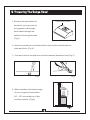
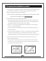
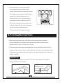
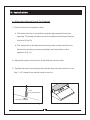
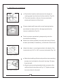
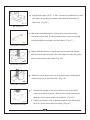
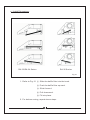
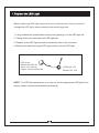
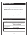
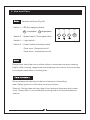
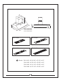
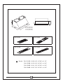
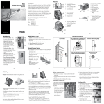
OPERATION
MANUAL
? SPEEDS : 3
? LED Light
R-33L Series
R-34L Series
R-35L Series
Please read and save this guide through before using your range hood
Store the guide away in a safe place so that you will know where it is
when you want to refer to it
Table of Contents
A.
Important Safety Instructions
B.
Safety Notes
C.
To o l s a n d M a t e r i a l s R e q u i r e d
D.
Ducting
E.
Preparing the Range Hood
F.
Preparing the Installation Location
-------------------------------------------------------------- P.3
- - - - - - - - - - - - - - - - - - - - - - - - - - - - - - - - - - - - - P.4
- - - - - - - - - - - - - - - - - - - - - - - - - - - - - - - - - - - - - - - - - - - - - - - - - - - - - - - - - - - - - - - - - - - - - P.4
G. Providing Electrical Power
H.
----------------------------------------- P.1
----------------------------------------------- P.5
------------------------------------- P.6
-------------------------------------------------- P.7
Installation------------------------------------------------------------------------ P.9
a, Mounting Range Hood to Cabinet
b , Wall mount installation
c , Install Accessory
------------------------------------------- P.9
--------------------------------------------------------- - P.10
------------------------------------------------------------------ P.12
I.
Replace the LED Light ---------------------------------------------------- P.13
J
Maintenance Instruction
K.
Troubleshootings
L.
Use and Care
----------------------------------------------------------- P.14
------------------------------------------------------------- P.14
------------------------------------------------------------- P.15
M. Parts Layout Diagrams ----------------------------------------------------------------- P.16
N.
Circuit Diagrams
O. A c c e s s o r i e s
P.
------------------------------------------------------------------ P.19
- - - - - - - - - - - - - - - - - - - - - - - - - - - - - - - - - - - - - - - - - - - - - - - - - - - - - - - - - - - - - - - P.20
Specifications ----------------------------------------------------------------- P.20
Q. Diagrams ------------------------------------------------------------------------ P.21
WARNING
Due to sharp edge, please wear " Safety Workman Gloves"
for installation, cleaning, light bulb changing and
dismantling to reduce the risk of any bodily injuries.
Safety Workman Gloves
A. Important Safety Insturctions
Read and Save These Instructions
CAUTION- To reduce risk of fire and to properly exhaust air, make sure
to properly exhaust air. Be sure to duct air outside- Do not
vent exhaust air into spaces within walls, ceilings, attics,
crawl spaces, or garages.
WARNING- To reduce the risk of fire or electric shock, do not use this fan
with any solid- state speed control device.
WARNING- TO REDUCE THE RISK OF FIRE, ELECTRIC SHOCK, OR INJURY,
OBSERVE THE FOLLOWING:
A. Use this unit only in the manner intended by the manufacturer.
If you have questions, contact the manufacturer.
B. Before servicing or cleaning the unit, switch power off at service
panel to prevent power from being switched on accidentally.
C. When the service disconnecting means cannot blocked, securely
fasten prominent warning device such as a tag to service panel.
CAUTION- For general ventilating use only. Do not use to exhaust
hazardous or explosive materials and vapours.
WARNING- TO REDUCE THE RISK OF A RANGE TOP GREASE FIRE:
A- Never leave surface units unattended at high settings. Boil over
cause smoking and greasy spillovers that may ignite. Heat oils
slowly on low or medium settings.
B- Always turn hood on when cooking at high heat or when cooking
flaming foods. (ie, Craepes suzetter, charries jubilee, peppercorn
beef flambe)
C- Clean ventilating fans frequently. Grease should not be allowed
to accumulate on fan or filter.
D- Use proper pan size. Always use cookware appropriate for the
size of the surface element.
1
WARNING- To reduce the risk of injury in the event of a range top grease
fire, observe the following:
A- SMOTHER FLAMES with a close- fitting lid, cookie sheet,
or metal tray, then turn off the burner. Be careful to prevent
burns. If the flames do not go out immediately, EVACUATE
AND CALL THE FIRE DEPARTMENT.
B- NEVER PICK UP A FLAMING PAN - You may be burned.
C- DO NOT USE WATER including wet dishcloths or towelsa violent steam explosion will result.
D- USE AN EXTINGUISHER ONLY IF:
1. You know you have a CLASS ABC extinguisher, and you
already know how to operate it.
2. The fire is small and contained in the area where it started.
3. The fire department is being called.
4. You can fight the fire with your back to an exit.
WARNING- Sufficient air is needed for proper combustion and
exhausting of gases through the flue (chimney) of fuel burning
equipment to prevent back drafting. Follow the heating equipment
manufacturer's guideline and safety standards such as these
published by the National Fire Protection Association (NFPA),and
the American Society for Heating. Refrigeration and Air
Conditioning Engineers (ASHRAE), and the local code authorities.
Keep the range hood clean.
WARNING- To reduce the risk of fire, use only metal duct work.
2
B. Safety Notes
1. All electrical work must be done in accordance with local and/or national
electrical code as applicable for safety. This product must be grounded
if your are unfamiliar with methods of installing electrical wiring, secure
the services of a qualified electrician.
2. Turn off power at service entrance before installing wiring or servicing
this product. (120 volt for range hood. 220 volt for electric range if any)
3. Turn off power to avoid risk of fire, electric shock, or injury for cleaning
or maintenance such as lubrication.
4. Fireplaces, gas furnaces, water heaters, require proper flow of
combustion air and exhaust. Make sure this flow is not altered when
using any exhaust fan.
5. Please read specification label on product for further information and
requirements.
6. Please wear "Safety Gloves" for installation, cleaning, light bulb
changing and dismantling to reduce the risk of any injuries.
CAUTION- To reduce the risk of fire and to properly exhaust air, be
sure to duct air outside. Do not vent exhaust air into spaces
within walls or ceilings or into attics crawl spaces or garages.
3
C. Tools and Materials Required
Drill, electric of ratchet drive, with 3/16" wood bit (for drilling starter
holes and 1 ¼ ” wood bit (to drill an access holes in the cabinet or
kitchen wall for the electric power line)
One common screwdriver.
Plier (for opening electrical knockout).
Two 1" (thick)x2" (wide)x12" (approximate length) wood strips for
recessed bottom kitchen cabinet installation only. (Purchase locally).
Electrical wire and supplies to comply with local cords.
Four 1 ¼ ” long flat head wood screws (purchase locally) to mount
wood strips.
Pencil and ruler for marking locations. Saber saw or keyhole saw for
cutting the 1"x2" wood strips to length.
D. Ducting
This style of range hood must be vented via ducting to the outside of the
house. Follow general rules when ducting the hood: Use correct size of
ducting at least 6" round, do not reduce size of ducting, make all turns
gradual, no short corners. If ducting ran will be longer than 10 feet enlarge
duct by at least 1" inch diameter after each 10 feet. Tape all joints in ducting
and all gasketed openings on hood for a tight seal.
For round ducting from the top:
Fit the gray or while plastic (Included) over the circular opening on top in order
to provide a tight seal for ducting to attach to. The duct ring is designed
to fit 6"and 7" ducting.
4
E. Preparing The Range Hood
1. Remove the top electrical
Electrical Knockout
knockout, you may plan to
bring power to the range
hood either through the
cabinet or through the wall
(Fig.1)
Fig.1
2. Insert a screwdriver into the knockout slot and bend the knockout
back and forth. (Fig.2)
3. You may have to use pliers to pull the loosened knockout free.(Fig.3)
Fig.3
Fig.2
28”-32”
4. When installed, the bottom edge
of your range hood should be
28" ~ 32" above the top of the
cooking surface. (Fig.4)
Fig.4
5
F. Preparing The Installation Location
1. If you want to move the electric range to make room for working on the cabinet
turn off the 220 volt power for the electric range at the service entrance.
2. Before moving a gas range, shut off the gas.
NOTE: SKIP FOLLOWING STEPS 3A THROUGH 3D IF THE HOOD IS TO BE
MOUNTED ON A CABINET WITH A FLUSH BOTTOM .
3. For installation onto a recessed bottom cabinet:
a. Measure the space (under the cabinet between the inside front edge and
inside back edge (Fig.5). With a saber saw, cut two 1"x2" wood filler strips
(purchased locally) to fill in the bottom of the cabinet.
b. Start a 1 ¼ " long wood screw (purchased locally) about 3" from each end
of the 1"x2" wood strips (Fig.6)
c. Position the strips on the cabinet bottom and screw the strips securely to
the cabinet (Fig.7)
d. For a more secure installation, drill four 3/16" holes from inside the cabinet,
down into the wood filler strips. Insert screws into the starter holes in
cabinet and tighten screws until wood filler strips are secured under cabinet.
4. Center the hood in place beneath the cabinet and flush with the front of the
cabinet. Mark the following:
a. The six keyhole mounting slots for the hood. Mark these onto the bottom of
the cabinet; or, if the cabinet bottom is recessed. Onto the wood strips (Fig.7)
b. The electrical knockout hole. (Fig.1)
Fig.6
Fig.5
6
c. Screw the four 1" wood screws (for
mounting the hood) into the exact
center of the arrow and into the keyhole
mounting slots marked on the cabinet
bottom (for flush installations), or
marked on the 1” x2” wood strips (for
Strips secured
recessed cabinet installation) (Fig.7)
Do not turn the mounting screws in all
Fig.7
the way. Allow 3/8" of screw to project,
so the hood can be fitted place.
(The screws will be tightened later)
G. Providing Electrical Power
1. After turning off the proper 120 volt circuit at the service entrance,
drill out the electrical power line access hole marked on the cabinet
bottom or wall. Use a 1 ¼ ”wood bit. (Fig. 8)
2. Fish the electrical power line through the access hole drilled in the wall or
bottom of the cabinet. Attach an appropriate connector (purchased locally)
to the end of the power line for the type of wiring being installed. Follow all
codes. (Fig.9)
Safety Warning:
If drilling into the walls, be careful not to cut existing electrical cables,
which would create a hazard.
Color:
green/white/black
1
" bit
Connecter
Fig.8
Fig.9
7
WIRING TO POWER SUPPLY
SAFETY WARNING
RISK OF ELECTRICAL SHOCK. THIS RANGE HOOD MUST BE PROPERLY
GROUNDED. MAKE SURE THIS IS DONE BY SPECIALIZED ELECTRICIAN
IN ACCORDANCE WITH ALL APPLICABLE NATIONAL AND LOCAL
ELECTRICAL CODES. BEFORE CONNECTING WIRES, SWITCH POWER OFF
AT SERVICE PANEL AND LOCK SERVICE PANEL TO PREVENT POWER
FROM BEING SWITCHED ON ACCIDENTALLY.
Connect the electrical wires.
- Connect three wires (black, white and green) to house wires and
cap with wire connectors. Connect according to color:
black to black, white to white, and green to green as shown on
Figure A.
- If necessary to hide the electrical wire connections, push wires
back into the wiring box. Access the wire connections underneath
the hood. Make sure wires do not slip between motor or any
moving parts to prevent any damage.
Figure. A
Wire Connector
8
H. Installation
a. Mounting Range Hood To Cabinet
1. Position the hood in place so that :
a. The electrical line is routed through the appropriate Knockout
opening. This step will have to be accomplished while positioning
the hood (Fig.10)
b. The large part of the keyhole mounting slots on the hood fit onto
the hood mounting screws projecting from the bottom of the
cabinet. (Fig.11)
2. Adjust the hood so the front is flush with the cabinet front.
3. Tighten the hood mounting screws all the way into the cabinet or into
the 1" x 2" wood strips so the hood is secure.
Color:
green/white/black
Fig.11
Knockout opening
Fig.10
Fig.11
9
b. Wall Mount Installation
ROOF CAP
a. Decide the location and measure the length of
PIPE
WALL CAP
ROUND
ELBOW
venting pipe from the hood to the outside. (Fig.12)
CABINET
HOOD
Fig.12
b. The less transition, elbows, the more exhaust
power performance of the hood.
Prepare back wall frame with cross framing lumber
(purchase locally) and fix in the appropriation for
secure installation (Fig.13)
Fig.13
Test for proper operation by temporarily wire the
hood before installing.
Attach two rubber stands (included) with two (4*8mm)
screws (included) if necessary, to the back of the hood.
Hood-Mounting
Bracket
Attach the hood - mounting bracket to the back of the
hood with six (3/16" x 3/8" ) screws (included) (Fig.14)
Rubber Stand
Fig.14
RA-33/RA-34 Series
a. Mark the levelling of the hood position two mounting
screws (not included) on the wall, leaving 1/8 away
from the wall.
b. Align hood-mounting bracket to the screws on the
Fig.15
RA-33/RA-34 Series
wall and hook into place as Fig.15, Tighten screws
to secure hood to the wall.
10
Apply with eight (3/16" x 3/8" ) screws (included) to fix the
Hoo
d-M
oun
t in g
two hood-mounting brackets (included) to the back of
Bra
cke
ts
the hood. (Fig.16 )
Fig.16
RA-35 Series
Mark the desired position of the duct cover mounting
bracket on the wall. Fix and secure duct cover mounting
bracket with two screws (not included). (Fig.17 )
Fig.17
RA-33/RA-34 Series
Aluminum or
Steel Pipe
Apply with aluminum or steel pipe to connect the plastic
Duct Tape
exhaust duct on the hood. Use duct tape to make all joints
6” Round
Plastic Exhaust
7” Round Adapter
secure and ensure air tight. (Fig.18 )
Fig.18
RA-33/RA-34 Series
1
Slide the inner duct cover up 2 inches before sliding the
entire duct cover on the hood. (Fig.19 )
2
Fig.19
RA-33/RA-34 Series
1. Adjust the height of the inner duct cover to the duct
cover-mounting bracket. Secure the inner duct cover
with two (4 x 8 mm) screws (included) (Fig.20 )
Fig.20
RA-33/RA-34 Series
2. Fasten out duct cover to plastic plate on the hood with
four (4 x 8 mm) screws (included) (Fig.20 )
11
c. Install Accessory
RA-33/RA-34 Series
RA-35 Series
Fig.21
1. Refer to Fig. 21 ① Slide the baffle filter into the hood.
② Push the baffle filter up ward.
③ Slide forward.
④ Pull downward.
⑤ Fit into place.
2. For bottom casing, repeat above steps.
12
I. Replace the LED Light
Before replacing LED light ensure the unit is switched off, when you want to
change the LED light, please always wear working gloves.
1. Using suitable tool (small slotted screw driver) gently pry off the LED light set.
2. Taking off the wire connecter with LED light set.
3. Replace a new LED light set and reconnect the wire to the connector.
4. Before push back the original LED light position, test the LED light.
LED driver:
Model: HP1500-36
input: 100~240vdc
output: 3.6vdc=1500maH
LED light: 1W
Model: HP-15A
NOTE : For LED light replacement, you may not find the appropriate LED lights from
market, please contact with distributor(s)/dealer(s).
13
J. Maintenance Instruction
1. Maintenance should be important than repair. Please take care of the
needed maintenance in order to secure and extend the excellent
functions and using life.
Note: Before repairing the range hood. Disconnect the power source.
2. After using the machine, wipes the machine by neutral detergent in
order to keep it clean and maintain the appearance with brightness
and sanitation.
3. When the level of dirty oil of the collector reached 4/5 of height, it has to
be removed in order to avoid overflowing and pollution.
K. Troubleshootings
Symptom
Correction
A. Check power source to see if it is normal.
Fan are not operatable.
Illuminating LED light
does not word
B. Check power inlet plug to see if it is
plugged firmly into it's socket.
A. Disconnect the power source.
B. Check LED light, replace it with a new
one if it is burned out.
A. Check for damaged vanes.
Hood vibrates.
B. Check if exhaust duct is secured.
14
L. Use and Care
Note:
Operate switches (Fig.22)
Switch 1 : LED Fan speed indicator.
3
- Low speed
1
④
③
②
①
- High speed
Switch 2 : Speed switch (Three speed fan)
8
Switch 3 : Light switch
Fig.22
Switch 4 : Power switch and delay switch.
Push once : Delayed shut off.
Push twice : Immediate shut off.
Note:
Range hood should be turn on either before or the same time when cooking
begins. After cooking, range hood should be kept on for about 3 more minutes
for complete ventilation of cooking odor.
Care Instruction:
Please always pull the plug out before cleaning or dismantling,
wear 'Safety gloves' to reduce the risk of any injuries.
Exterior: Can be clean with any type of non-abrasive detergent and a clean
cloth. "Green Pad" or any metal type cleaning pad is not recommended for
exterior.
15
M. Parts layout diagrams
MODEL :
RA-3330C
3
RA-3336C
5
4
1
6
7
2
8
9
11
RA-3330C
10
RA-3336C
12-1
12
1.
Duct cover-Mounting bracket
7.
Control board
2.
Duct cover (Optional)
8.
Processor board
3.
Hood-Mounting bracket
9.
LED driver
4.
Rubber stand
10. Capacitor
5.
Hood casing
11. Squirrel cage
6.
LED light
12. Aluminum filter (12-1)
16
MODEL :
3
RA-3430B
5
RA-3436B
RA-3442B
RA-3448B
4
1
6
7
8
2
9
10
11
RA-3430B
RA-3436B
13-1
12-1
13
12
RA-3442B
RA-3448B
13-3
13-2
12-2
12-3
1.
Duct cover-Mounting bracket
8.
Processor board
2.
Duct cover (Optional)
9.
LED driver
3.
Hood-Mounting bracket
10. Capacitor
4.
Rubber stand
11. Squirrel cage
5.
Hood casing
12. Stainless steel spacer
6.
LED light
13. Baffle filter
7.
Control board
17
MODEL :
RA-3530B
1
RA-3536B
RA-3542B
RA-3548B
2
3
5
4
7
6
8
9
10
RA-3530B
RA-3536B
12-1
12
11-1
RA-3548B
RA-3542B
12-3
12-2
11-2
11-3
1.
Duct cover (Optional)
7.
Capacitor support
2.
Duct cover -Mounting bracket
8.
LED driver
3.
Hood casing
9.
Capacitor
4.
LED light
10. Squirrel cage
5.
Control board
11. Stainless steel spacer
6.
Processor board
12. Baffle filter
18
N. Circuit Diagrams
Fig.23 Details the internal electrical circuit of this range hood unit.
Any faults with this unit should only be attended to by a
qualified technician.
White
Yellow
Orange
Red
Brown
Black
Yellow
Capacitor
Brown
White
Blue
Gray
Red
Motor
Yellow
Brown
White
Blue
Gray
Red
Motor
Brown
Black
LED driver
Black
LED light
Red
Black
Power
White
Ground
Fig.23
Electrical Schematic Diagram
19
O. Accessories
Spare Parts Contents
1
Part
WALL HOOD
Item
OPERATION
MANUAL
RA-33 Series
RA-34 Series
RA-3 5 Series
Description
Spare Parts Contents
Spec.
Q'ty Item
1
Manual
Part
4
Spec.
Q'ty
Screws
Ø4x32
4
Screws
Ø3/16 " x3 "
2
Plastic
Screws
1/4"
4
Description
2
3
Round
Collar
1
6"/7"
Toggle Bolts #3/16"x3"
2
Screws package
Please read and save this guide through before using your range hood
Store the guide away in a safe place so that you will know where it is
when you want to refer to it
P. Specifications
Specifications
Revolutions
RA-3330C / RA-3336C
RA-3430B / RA-3436B / RA-3442B
Low - 590 50 R.P.M. High - 1650 50 R.P.M.
180W
Consumption - Motor
Consumption - Lamp
1W x 2 / 3.6Vdc / 1500maH
Rotation
Diameter Exhausting Duct
Specifications
Revolutions
6 " / 7 " Round Outlets adapter
120V / 60 Hz
Brushed Stainless Steel
RA-3530 / RA-3536 / RA-3542
180W
1W x 2 / 3.6Vdc / 1500maH
Rotation
Diameter Exhausting Duct
Squirrel Cage
6 " / 7 " Round Outlets adapter
Voltage
Appearance Treatment
RA-3548
Low - 690 50 R.P.M. High - 1660 50 R.P.M.
Consumption - Motor
Consumption - Lamp
x3
Squirrel Cage
Voltage
Appearance Treatment
RA-3448B
120V / 60 Hz
Brushed Stainless Steel
* Specifications subject to change without prior notice.
20
x3
11
.2”
6”
.6”
6”
12”
10
2/3”
Min: 19.7”
Max: 35.4”
Q. Diagrams
29-3/4”(RA-3330)
”
29-3/4”(30”)
35-3/4”(36”)
Model : RA-3330 : W 29-3/4 " x D 22 " x H 6 "
RA-3336 : W 35-3/4 " x D 22 " x H 6 "
21
22”
22”
15”
35-3/4”(RA-3336)
15”
22
Min: 19.7”
Max: 35.4”
.2”
22
”
29-3/4" (RA-3430)
35-3/4" (RA-3436)
41-3/4" (RA-3442)
47-3/4" (RA-3448)
RA-3430B
RA-3436B
RA-3442B
RA-3448B
Model : RA-3430 : W 29-3/4 " x D 22 " x H 9 "
RA-3436 : W 35-3/4 " x D 22 " x H 9 "
RA-3442 : W 41-3/4 " x D 22 " x H 9 "
RA-3448 : W 47-3/4 " x D 22 " x H 9 "
22
12”
9”
11
2/3”
.6”
9”
10
3.15”
29-3/4" (RA-3530)
35-3/4" (RA-3536)
41-3/4" (RA-3542)
47-3/4" (RA-3548)
RA-3530B
RA-3536B
RA-3542B
RA-3548B
Model : RA-3530B : W 29-3/4 " x D 24 " x H 18 "
RA-3536B : W 35-3/4 " x D 2 4 " x H 18 "
RA-3542B : W 41-3/4 " x D 2 4 " x H 18 "
RA-3548B : W 47-3/4 " x D 2 4 " x H 18 "
23
Limited Warranty
Windster Hoods Inc. warrants this product against defects in material or
workmanship as follows:
1) Labor: For a period of one (1) year from the date of purchase, if this product
is determined to be defective, Windster will repair or replace the product, at its
option, at no charge. After the warranty period, you must pay for all labor
charges. During the “labor” warranty period there will be no charge for labor.
2) Parts: In addition, Windster will supply, at no charge, new or rebuilt
replacements in exchange for defective parts for a period of two (2) years.
After the warranty period, you must pay for all parts costs. During the “parts”
warranty period, there will be no charge for parts
You must carry-in or mail-in your product during the warranty period. This warranty
only applies to products purchased and serviced in the United States or Canada.
What Is Not Covered By These Warranties:
1) Conditions and damages resulting from any of the following:
?
Improper installation, delivery, or maintenance.
?
Any repair, modification, alteration or adjustment not authorized by the
manufacturer or an authorized service dealers.
?
Misuse, abuse, accidents, or unreasonable use.
?
Incorrect electric current, voltage or supply.
?
Improper setting of any control.
?
Improper chemical cleaning.
2) Light Bulbs
3) Products purchased for commercial or industrial use (such as in a hotel, office,
restaurant, or other business)
4) Damage due to earthquake, flood, storm, etc.
Defective Products:
All products will be inspected, tested, and carefully packed by the manufacturer
before shipping to customers. Products that are damaged during transit can only be
exchanged for the same product, under the condition that the customer must get a
RMA (Return Merchandise Authorization) from Windster. When products are
received defective, you must notify us within the 3 business days of receiving the
package. Replacement products are only shipped when the RMA is issued. NO
EXCEPTIONS.
Return Policy
Windster offers only the best and highest quality products. If you are not satisfied
with your purchase, please contact us within 3 business days of product arrival to
obtain a Return Merchandise Authorization (RMA). Returns sent without a RMA will
not be accepted. There will be a 25% re-stocking fee for every returned items.
Shipping fee will also be deducted from the original purchase price. When returning a
package, please include a copy of your purchase receipt. Use the original shipping
box and packing materials and completely remove or cover the original shipping label.
Make sure that products are in brand new condition, uninstalled, un-drilled, and
contain everything that came with the package as when you first received it. If any
parts or manuals are missing, we have the right not to accept the return.
We suggest that you use a traceable and reputable carrier of your choice to ship your
return. Your credit or refund will be processed within 10-14 business days from the
date we receive your return.
2102 N. Seaman Ave., S. El Monte, CA 91733 TEL:626-350-1015 626-350-5215 FAX:626-350-1254
Website: www.windsterhood.com Email: [email protected]
WINDSTER
TM
www.windsterhood.com
2102 N. Seaman Ave.,
S. El Monte, CA 91733
TEL:(626)350-1015
(626)350-5215
FAX:(626)350-1254
© 2006-2008 Windster Hoods, Inc.
Specifications subject to change without notice.