1
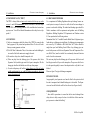
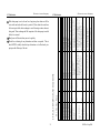
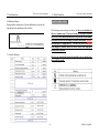
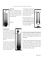
Operation &Installation Manual The ESP Ecocent Model: ESP 400-200Ltr ESP 400-250Ltr ESP 400-300Ltr Please keep this manual safely and read it carefully before installation or operation ©ESP Ltd. Sept 2008 Warning!!!! Contents READ THIS BEFORE INSTALLING THE UNIT. Preface………………………………………………………………..3 All un-vented water heating systems above 15 litre (this includes the ESP Hot Water ASHP‟s) MUST be installed to meet the requirements of the Building Regulations. It is a legal requirement that the local Building Control Officer be notified of any proposed installation of un-vented water heating systems over 15 litre capacity. General Requirements………………………………………………..4 Specs…………………………………………………………………6 Function Presentation………………………………………………..8 Installation…………………………………………………………...9 Commissioning……………………………………………………...18 Furthermore, it must be fitted by an installer who has successfully completed a recognised course in the installation of un-vented heating systems such as CITB. Failure to properly fit the unit may affect its efficiency and invalidate any guarantee. Maintenance…………………………………………………………19 User Instructions…………………………………………………….22 Safety Precautions…………………………………………………...24 Guarantee……………………………………………………………26 Spare Parts…………………………………………………………...27 Appendix 1…………………………………………………………..27 Appendix 2…………………………………………………………..36 Safety requirements in the UK call for an expansion space (internal or external), safety devices to prevent the stored water exceeding 100°C, and pipework to convey discharged hot water safely away from the safety devices. 2 ©ESP Ltd. Sept 2008 Preface PLEASE NOTE FOR TRANSPORT AND STORAGE!!!: Hot water air source heat pump Storage The unit must be stored and/or transported in its shipping container in an upright position and kept dry. For transport over short distance, and provided due care is exercised, an inclination angle of up to 60 degree is permitted. Both during transport and storage, ambient temperatures of - 20 to +70 are the limits. Transport using a forklift When transporting by fork lift, the unit must remain mounted on the pallet. The lifting height should be kept to a minimum. Due to its top-heaviness, the unit must be secured against tipping over. To prevent any damage, the unit must be placed on a level surface! Manual transportation For the moving the unit by hand, the wooden pallet can be used for bottom lifting. Using ropes or carrying straps is permissible with great care being taken not to damage the unit. With all manual handling, care must be taken that the max. permissible inclination angle of 60 degree is not exceeded. If transport in an inclined position cannot be avoided, the unit MUST be left upright for at least 90 mins. in the planned installation position before being installed. Failure to do this may cause serious damage to the unit during and following installation. This manual includes the necessary information about installation, and maintenance of the Ecocent. Please read this manual carefully before you install or carry out maintenance on the unit. When installing the unit , please carry it out strictly according to the manual. Please do not switch the unit on until you are sure that it has been properly installed. The installer should explain to the end user how to operate and maintain the unit before handing over the unit to the end user. Also, the installer should advise the end user to read the manual fully before operating the unit. The supplier and/or manufacturer of the unit will not be responsible if someone is injured or the unit is damaged, as a result of installation, operation and/or maintenance that is not in line with this manual. Further, improper installation, operation and/or maintenance, and failure to maintain the unit as per this manual will invalidate any unit warranty or guarantee. The manual may be altered and/or updated in any way at the sole discretion of the supplier and/or ESP without notice. 3 ©ESP Ltd. Sept 2008 1. General Requirements Hot water air source heat pump 1. General Requirements Hot water air source heat pump • Cold Water Combination Valve (comprises Pressure Reducing Valve, Strainer, and Check Valve) • Expansion Core Unit (comprises Check Valve and Expansion Valve) • Temperature/Pressure Relief Valve (set at 90 - 95°C/1 Mpa (7bar)) • Tundish (included in Cold Water Combination Valve pack) • Factory fitted Indirect Thermostat and Thermal Cut-out IMPORTANT : PLEASE READ AND UNDERSTAND THESE INSTRUCTIONS BEFORE INSTALLING THE ESP Ecocent (“DHW ASHP” or “unit”). INCORRECT INSTALLATION WILL INVALIDATE ANY GUARANTEE. THIS UNIT IS NOT INTENDED FOR USE BY PERSONS (INCLUDING CHILDREN) WITH REDUCED PHYSICAL, SENSORY OR MENTAL CAPABILITIES, OR LACK OF KNOWLEDGE AND EXPERIENCE, UNLESS THEY HAVE BEEN GIVEN SUPERVISION OR INSTRUCTION CONCERNING THE USE OF THE UNIT BY A PERSON RESPONSIBLE FOR THEIR SAFETY. Further detail is provided on the above at Appendix 1 and you should make sure that you read the Appendix thoroughly before undertaking any installation or other work on the unit. THE UNIT MUST BE INSTALLED, COMMISSIONED AND MAINTAINED BY A COMPETENT INSTALLER IN ACCORDANCE WITH BUILDING REGULATION G3 (ENGLAND AND WALES), TECHNICAL STANDARD P3 (SCOTLAND) OR BUILDING REGULATION P5 (NORTHERN IRELAND) AND THE WATER FITTING REGULATIONS (ENGLAND AND WALES) OR WATER BYELAWS (SCOTLAND). FOLLOWING INSTALLATION AND COMMISSIONING, THE OPERATION OF THE UNIT SHOULD BE EXPLAINED TO THE USER AND THESE INSTRUCTIONS LEFT WITH THEM FOR FUTURE REFERENCE. 1.2 SITING THE UNIT The unit must be vertically floor mounted. It can be placed anywhere convenient provided the discharge pipe(s) from its safety valves can be correctly installed. Areas that are subject to freezing must be avoided. Ensure that the floor is of sufficient strength to support the weight of the unit when full with water. Pipe run lengths should be kept as short as possible for maximum economy and efficiency. Access to associated controls, immersion heaters and indirect controls must be possible for servicing and maintenance of the unit. Please do not install valves or pipework (except discharge pipe) within 50mm (2”) of the T&P relief valve to allow insulation to be fitted. The insulation is important to ensure heat and energy conservation. PLEASE NOTE THAT THERE ARE ESSENTIALLY 2 UNITS COMBINED INTO ONE IN THE ESP DHW ASHP AND YOU MUST BE SURE TO UNDERSTAND BOTH ELEMENTS—THE INDIRECT PRESSURIZED CYLINDER AND THE AIR SOURCE HEAT PUMP. IMPORTANT NOTE: DO NOT SITE THE UNIT IN THE SAME ROOM AS AN OPEN FLUED APPLIANCE OR A ROOM WHERE AN OPEN FLUED APPLIANCE TAKES ITS COMBUSTION AIR FROM UNLESS THE MATTER HAS BEEN CAREFULLY CONSIDERED AND ADEQUATE DUCTING AND VENTILATION HAS BEEN PROVIDED FOR THE UNIT (THE DHW ASHP). 1.1 COMPONENT CHECK LIST Before commencing installation check that all the components for your unit are contained in the package. The following components are supplied as standard with the unit : • Factory fitted immersion heater (s) and thermal controls . 4 ©ESP Ltd. Sept 2008 1.General Requirements Hot water air source heat pump 1.General Requirements Please be sure to use appropriate lifting equipment when moving the unit. Hot water air source heat pump 1.4 OUTLET/TERMINAL FITTINGS (TAPS, ETC.) The unit can be used in conjunction with most types of terminal fittings. It is helpful in many mixer showers to have balanced hot and cold water supplies; in these instances the balanced cold water supply should be tee‟d off the supply to the unit immediately after the Cold Water Combination Valve (see Figures 4 and 5). Branches to cold drinking water outlets should be taken before the valve. 1.3 WATER SUPPLY Bare in mind that the mains water supply to the property will be supplying both the hot and cold water requirements simultaneously. Therefore, it is important that the maximum water demand be assessed and the water supply checked to ensure this demand can be met. NOTE: Accessories should have a rated operating pressure of at least 0.8 MPa (8 bar). NOTE: A high mains water pressure will not always guarantee high flow rates. Wherever possible the main supply pipe to the unit should be in 22mm. The minimum mains water supply requirements should be 0.15 MPa (1.5 bar) working pressure and 20 litres per minute flow-rate. At these values outlet flow -rates may be poor if several outlets are used simultaneously, the higher the available pressure and flow-rate the better the system performance will be. 1.5 LIMITATIONS The unit should not be used in any of the following instances: Solid fuel boilers or any other boiler in which the energy input is not under effective thermostatic control, unless additional and appropriate safety measures are installed. Gravity circulation primaries. Steam heating plant unless additional and appropriate safety devices are installed. Ascending spray type bidets or any other Class 5 back syphonage risk requiring that a appropriate air gap be employed. Water supplies that have either inadequate pressure or where the supply may be intermittent. Situations where it is not possible to safely pipe away any discharge from the safety valves. Areas where the water contains a high proportion of solids, eg. suspended matter that could block the strainer, unless adequate filtration can be ensured. Where another appliance in the room is vented by way of an open flu. The installation must be carried out in accordance with the relevant requirements of: The unit has a design operating pressure of 3 bar which is controlled by the Cold Water Combination Valve. The Cold Water Combination Valve can be connected to a maximum mains supply pressure of 1.6 MPa (16 bar). The water supply must be of wholesome water quality (Fluid Category 1 as defined by the Water Supply Regulations 1999). The unit MUST be sited on a level surface, otherwise this could cause problems with condensate draining from the heat pump section of the unit in to the condensate drain. An inline strainer and scale inhibitor (WRAS approved) must be fitted “in line” on the water supply to the unit. Failure to fit these will invalidate the unit warranty/guarantee. All fittings must be WRAS approved. 5 ©ESP Ltd. Sept 2008 1.General Requirements Hot water air source heat pump 2.Specs A) The appropriate Building Regulations: either The Building Regulation (England), The Building Regulations (Scotland) or Building Regulations (Northern Ireland). B) The Water Fittings Regulations (England and Wales) or Water Bye laws (Scotland). C) Any other applicable Regulations. Failure to observe any of the above conditions will invalidate the warranty/gurantee. Hot water air source heat pump 2.1 APPEARANCE 1.6 HOT WATER AIR SOURCE HEAT PUMP PACKAGE The unit will be supplied with the fittings detailed in section 1.1 above. 2.2 CHARACTERISTICS Good looking and efficient The attractive design allows the unit to be placed in the open in finished utility spaces and basements; depending on ambient conditions, the cost of operation can be 25% of that of an electric water heater, and can be used in locations unsuitable for solar hot water heating. Environmentally friendly and safer Produces no harmful emissions locally; there is no combustion of oil, coal, or natural gas. No carbon monoxide is produced and there is no open flame. Easy to operate and multiple heat sources Contains a timer for start and stop and an adjustment dial for easy setting of the water temperature; the unit can take heat from a number of sources - the outside environment, from an attic space, or from hot areas in light industrial environments. 6 ©ESP Ltd. Sept 2008 Hot water air source heat pump 2. Specs Hot water air source heat pump 2. Specs 2.3 DIMENSIONS 2.4 PERFORMANCE PARAMETER ESP 400 SERIES—150L/200L/250L/300LD Unit/mm Model ESP400 010-150L(D) 010-200L(D) 010-250L(D) 010-300L(D) kW 2.6 2.6 2.6 2.6 Water tank capacity L 150 200 250 300 Power input W 810 810 810 810 Running current A 3.7 3.7 3.7 3.7 V/PH/ 220/1/50 220/1/50 220/1/50 220/1/50 1 1 1 1 Rotary Rotary Rotary Rotary Heating capacity Power supply Compressor Number Compressor Rated outlet water tempera- °C 55 55 55 55 Max. outlet water tempera- °C 60 60 60 60 Air volume M³/h 450 450 450 450 Air pressure Pa 60 60 60 60 Mm Φ200 Φ200 Φ200 Φ200 dB(A) 49 49 49 49 Duct diameter Noise Water inlet size/outlet size Inch ¾" ¾" ¾" ¾" Auxiliary electrical heating kW 1.5 1.5 1.5 1.5 Net dimensions mm φ470≠1830 φ560≠1700 φ560≠1950 φ640≠1750 Net weight Kg 63 81 81 88 Shipping weight kg 68 78 86 93 Measuring conditions Instant heating: Ambient temperature 20/19,Water outlet 55°C Operating range (1).Ambient temperature range is 0-40°C (2). The max water temperature is 60°C Please note - Stabbings may vary by model. 7 ©ESP Ltd. Sept 2008 3.Function presentation 3.Function presentation Hot water air source heat pump Hot water air source heat pump Earthing 3.1 PLEASE NOTE: Heating capacity The unit absorbs energy from the air inlet location ambient conditions. If the air inlet temperature is low, heating capacity will show variation from standard conditions. The unit MUST be earthed and facility is provided for this in the unit design - be sure to have the unit properly earthed during installation. You must have the unit fitted by a suitably qualified installer - we accept no responsibility for units that are not fitted by fully qualified installers. Also, failure to have the unit fitted by a suitably qualified installer will invalidate the warranty/guarantee of the unit. 3 minutes protection When the unit stops, if you restart the unit or turn on the manual switch, the unit will not run for 3 minutes. This is built in protection for the compressor. Heating mode running If the ambient temperature is too high, to protect the unit, the fan motor will stop running. Defrosting When in heating mode, the unit will defrost automatically. The fan motor will stop running when the unit is defrosting. Working condition The unit should be run at ambient temperatures of 0-40 deg. The unit includes sophisticated electronic devices - do not fill the heating system with water from lake, river water or groundwater and be sure to put an inline strainer and scale inhibitor in the cold water feed - failure to do so will invalidate the warranty/guarantee. Power off If the power supply is off, the unit will stop running. If operation is disturbed by lightning, power grid fluctuations or similar, please turn the power supply off manually and then power on again to reset. 8 ©ESP Ltd. Sept 2008 Hot water air source heat pump 4. Installation 4. Installation 4.1 INSTALLATION DIAGRAM Hot water air source heat pump 4.2 PIPE FITTINGS All pipe connections to the unit are 22mm. The fittings are also threaded 3/4” BSP male should threaded pipe connections be required. Air ducts must be at least in 6 inch rigid pipe. 4.3 COLD WATER SUPPLY A 22mm cold water supply is recommended, however, if a 15mm (1/2”) supply exists which provides sufficient flow (see section 2.3) this may be used. More flow noise may be experienced from small bore pipes due to the increased water velocity through them. The Cold Water Combination Valve supplied with the unit incorporates a full flow isolating valve which will enable the unit to be isolated from the mains supply for maintenance or servicing. To close the valve the black handle should be turned so that it lies at 90°C to the direction of flow. To open turn the handle so that it lies parallel to the direction of flow. An inline filter and an effective scale prevention device must be fitted to the cold feed. Please note: Circulation of the hot water, solar and heat reclaims is optional. Please contact Earth Save Products before using the primary coil. 4.4 COLD WATER COMBINATION VALVE (see Figure 2) The Cold Water Combination Valve must be sited close to the unit to allow the safety discharge pipe to run in to the tundish, in line with appropriate Regulations. The Expansion Valve connection must not be used for any other purpose. The Cold Water Combination Valve can be installed as a complete one-piece unit. The valve incorporates a factory set, non-adjustable Pressure Reducer/ Strainer, an Expansion Valve connection and a single Check Valve. The valve can be fitted in any orientation to suit the installation, however, ensure that the Valve is installed with the direction of flow arrows (stamped on the side of the brass body) pointing towards the unit. ATTENTION The one-way safety valve attached with the unit must be installed or it will cause damage to the unit and can cause injury in certain circumstances. Ensure that any damage to the unit caused prior to delivery is notified to the Supplier within 5 days of delivery. Failure to notify the Supplier within this time period will mean that any claims relating to damage will be rejected. 9 ©ESP Ltd. Sept 2008 4 . Installation Hot water air source heat pump 4 . Installation Hot water air source heat pump Should you wish to site the Expansion Valve on the Cold Water Combination Valve this can be done by unscrewing the connection nut beneath the Expansion Valve on the Expansion Core Unit and removing the Expansion Valve. The connecting nut and blanking plug should then be unscrewed from the Cold Water Combination Valve and replaced with the Expansion Valve. Note: if the Expansion Valve is fitted to the Cold Water Combination Valve the Expansion Core Unit should not be used as the Check Valve within it will prevent free passage of expanded water to the Expansion Valve. Ensure the discharge from the Expansion Valve can be correctly installed. If a balanced pressure cold water supply is required to a thermostatic shower mixer valve this may be tee‟d off the supply to the unit immediately after the Cold Water Combination Valve (see Figure 4). Branches to drinking water outlets should be taken before the valve to avoid the possibility of warm expanded water being drawn from the tap. 4.5 EXPANSION CORE UNIT (see Figure 3) Should a balanced pressure cold water supply be required for other cold water outlets the Expansion Core Unit supplied should be used. The Core Unit should be fitted into the pipework between the Cold Water Combination Valve and the unit (note direction of flow arrows). The cold water balanced draw off connection should be taken from between the Cold Water Combination Valve and the Expansion Core Unit (see Figure 5). The Expansion Valve connection on the Cold Water Combination Valve should remain blanked off using a blanking nut and seal. Ensure the discharge from the Expansion Valve can be correctly installed. 10 ©ESP Ltd. Sept 2008 4 . Installation Hot water air source heat pump 4 . Installation Hot water air source heat pump 4.6 DRAIN TAP A draining tap should be installed in the cold water supply to the unit between the Cold Water Combination Valve (or Expansion Core Unit if being used) and the heater at as low a level as possible It is recommended that the outlet point of the drain pipe work be at least 1 metre below the level of the heater (this can be achieved by attaching a hose pipe to the drain tap outlet spigot). 4.7 OUTLET PIPEWORK Ideally the pipework from the unit to the outlet fittings should be in 22mm pipe with short runs of 15mm pipe to showers and basin taps. Small bore pipe can also be used to suit some taps, but runs should be of minimum length. Pipe sizes may vary due to system 4.8 SECONDARY CIRCULATION If a secondary circulation system is required it should be installed as per Figure 6. The secondary return pipe should be in 15mm pipe and incorporate a check valve to prevent backflow. A suitable WRAS approved bronze circulation pump will be required with appropriate unions. On large systems, due to the increase in system water content, it may be necessary to fit additional expansion volume to the system by fitting an external expansion vessel to the secondary circuit. This should be done if the capacity of the secondary circuit exceeds 10 litres. Pipe capacities (copper) 15mm o/d = 0.13 litres per metre run (10 litres = 77m) 22mm o/d = 0.38 litres per metre run (10 litres = 26m) 28mm o/d = 0.55 litres per metre run (10 litres = 18m) Secondary circulation is NOT recommended for units being used on “Off Peak” electricity tariffs. 11 ©ESP Ltd. Sept 2008 4 . Installation Hot water air source heat pump 4 . Installation 4.9 T&P RELIEF VALVE (“TPRV”) The TPRV is factory fitted and must not be interfered with in any way and/or removed - under NO circumstances should the installer or end user tamper with the TPRV or the warranty/guarantee will be invalidated and serious damage may occur. You will find detailed information on this safety device at Appendix 2. Hot water air source heat pump 4.11 DISCHARGE PIPEWORK It is a requirement of Building Regulations that any discharge from an unvented system is conveyed to where it is visible, but will not cause danger to persons in or about the building. The tundish and discharge pipes should be fitted in accordance with the requirements and guidance notes of Building Regulations. Building Regulation G3 Requirements and Guidance section 4.10 are reproduced in the following sections. Information Sheet No. 33 available from the British Board of Agrément gives further advice on discharge pipe installation. For discharge pipe arrangements not covered by G3 Guidance or BBA Info Sheet No.33 advice should be sought from your local Building Control Officer. Any discharge pipe connected to the pressure relief devices (Expansion Valve and Temperature/ Pressure Relief Valve) must be installed in a continuously downward direction and in a frost free environment. The water may drip from the discharge pipe of the pressure relief device and that this pipe must be left open to the atmosphere. The pressure relief device is to be operated regularly to remove lime deposits and to verify that it is not blocked. Please see figure 7 for typical discharge arrangement. 4.10 WARNINGS i) Under no circumstances should the factory fitted TPRV be removed other than by approved, fully trained and experienced fitters. To do so will invalidate any warranty/guarantee or claim. ii) The Cold Water Combination Valve, in line strainer and scale inhibiting device must be fitted to the mains water supply to the unit. iii) No control or safety valves should be tampered with. iv) Water may drip from the discharge pipe of the pressure relief device (Expansion Valve) and this pipe must be left open to atmosphere. The discharge pipe should not be blocked or used for any other purpose. v) For units with primary coil facilities, please discuss use of the coil, and a suitable configuration for use, with ESP before proceeding to add a heat source to the primary coil. EXPANSION VESSEL An appropriately sized expansion vessel must be fitted to the system in which the unit is incorporated and it should discharge in to the tundish. The Expansion vessel can be fitted to the cold feed in to the unit (see Figures 4 and 6). G3 REQUIREMENT “...there shall be precautions...to ensure that the hot water discharged from safety devices is safely conveyed to where it is visible but will not cause danger to persons in or about the building.” 12 ©ESP Ltd. Sept 2008 4 . Installation Hot water air source heat pump 4 . Installation Hot water air source heat pump Examples of acceptable discharge arrangements are: i. ideally below a fixed grating and above the water seal in a trapped gully. ii. downward discharges at low level; i.e. up to 100mm above external surfaces such as car parks, hard standings, grassed areas etc. are acceptable providing that where children may play or otherwise come into contact with discharges a wire cage or similar guard is positioned to prevent contact, whilst maintaining visibility. iii. discharges at high level; e.g. into a metal hopper and metal down pipe with the end of the discharge pipe clearly visible (tundish visible or not) or onto a roof capable of withstanding high temperature discharges of water and 3m from any plastics guttering system that would collect such discharges (tundish visible). iv. where a single pipe serves a number of discharges, such as in blocks of flats, the number served should be limited to not more than 6 systems so that any installation discharging can be traced reasonably easily. The single common discharge pipe should be at least one pipe size larger than the largest individual discharge pipe (D2) to be connected. If unvented hot water storage systems are installed where discharges from safety devices may not be apparent i.e. in dwellings occupied by blind, infirm or disabled people, consideration should be given to the installation of an electronically operated device to warn when discharge takes place. G3 GUIDANCE SECTION 4.10 The discharge pipe (D1) from the vessel up to and including the tundish is generally supplied by the manufacturer of the hot water storage system. Where otherwise, the installation should include the discharge pipe(s) (D1) from the safety device(s). In either case the tundish should be vertical, located in the same space as the unvented hot water storage system and be fitted as close as possible and within 500mm of the safety device e.g. the TPRV. The discharge pipe (D2) from the tundish should terminate in a safe place where there is no risk to persons in the vicinity of the discharge, preferably be of metal and: a. be at least one pipe size larger than the nominal outlet size of the safety device unless its total equivalent hydraulic resistance exceeds that of a straight pipe 9m long i.e. discharge pipes between 9m and 18m equivalent resistance length should be at least two sizes larger than the nominal outlet size of the safety device, between 18 and 27m at least 3 sizes larger , and so on. Bends must be taken into account in calculating the flow resistance. Refer to Diagram 7 and Table 1 below. An alternative approach for sizing discharge pipes would be to follow BS 6700:1987 Specification for design, installation, testing and maintenance of services supplying water for domestic use within buildings and their curtilages, Appendix E, section E2 and table 21. b. have a vertical section of pipe at least 300mm long below the tundish before any elbows or bends in the pipe work. c. be installed with a continuous fall, and in a frost free environment. d. have discharges visible at both the tundish and the final point of dicharge, but where this is not possible or is practically difficult there should be clear visibility at one or other of these locations. Note: The discharge will consist of very high temperature water and steam. Asphalt, roofing felt and non-metallic rainwater goods may be damaged by such discharges and you must take this in to account when fitting the unit. Should such damage be caused, ESP will accept no liability for any consequent damage caused. 13 ©ESP Ltd. Sept 2008 4 . Installation Hot water air source heat pump 4 . Installation Table 1 - Sizing of copper discharge pipe (D2) for common T&P relief valve sizes Hot water air source heat pump THE FOLLOWING IS FOR REFRIGERANT ENGINEER ONLY: 1) Vacuum and filling Refrigerants. The unit is supplied pre-gassed. Should a refrigerant fill be required at any point, please note the following: When you have finished the connection between the heat pump and the hot water unit, you must create a vacuum in the hot water unit. See below pictures 6 & 7 below: A. Unscrew the screw cap of the high pressure valve on the heat pump, and connect the multiplex manometer to the check valve. B. Connect the vacuum pump to the multiplex manometer, then open them to create a vacuum in the hot water unit, making sure the absolute pressure is less than 70Pa, and lasts for 60 minutes. C. When you have finished the vacuum test, open the check valve to let the refrigerant go into the ASHP part of the unit. 4.12 HOW TO CONNECT TO THE HEAT PUMP As the heat pump is an integral part of the unit, please contact the manufacturer for additional information where required. PLEASE NOTE that only manufacturer approved engineers should carry out any work on the heat pump. Call the manufacturer for the name of an approved engineer in your area. 14 ©ESP Ltd. Sept 2008 4 . Installation Hot water air source heat pump 4 . Installation D. When you need to add the refrigerant, please do so as follows: Hot water air source heat pump IMPORTANT Do not allow any impurities to enter the refrigerant system 4) Insulation treatment As per the below picture, you must insulate all connecting pipes and you must use good quality, non flammable, PVC insulating material, of 15mm20mm thickness. (a) To keep the pipes in a tidy state, you may wrap the pipes together after being separately insulated. (b) Under no circumstances should you let electric wires come in to contact with the plumbing. NOTE: With the 400 Series, the ASHP and the cylinder are one unit and the above should be interpreted accordingly. 2) Controller system test Switch on the power to the unit, check the display of the wire controller-it will display the water temperature when the unit is on standby mode. If the wire controller display is showing an incorrect reading or an error code, please refer to Section 6.9. 3) Debug the cooling system a) On completing wiring of the unit, please release a little refrigerant from the low pressure side, or use the vacuum pump to create the vacuum in the system, until the pressure is below 70Pa. b) Once the unit is in vacuum, please open the high pressure valve and the low pressure valve until the pressure is balanced, then check the joints for leaks. c) Ducting—Please ENSURE that ducting is safely and appropriately fitted. 4.13 INDIRECT THERMAL CUT-OUT AND 2-PORT MOTORISED VALVE To comply with Building Regulations and to prevent the unit from overheating a 2-port motorised valve MUST be fitted to the primary flow to the indirect coil—See Figure 11 below Please note that this diagram may vary from model to model, but the principle does not. 4.14 WIRING All electrical wiring MUST be carried out by a competent electrician and be in accordance with the latest I.E.E. Wiring Regulations. The wiring block diagram is set out below in Picture 14. 15 ©ESP Ltd. Sept 2008 4.Installation Hot water air source heat pump 4. Installation The 2-port motorised valve MUST be wired in series with the Indirect controls (for the unit Indirect Thermostat and Thermal Cut-Out) such that the power supply to the valve is interrupted should either the Thermostat or Thermal CutOut operate. Wiring to external controls is made via the terminal block fitted. The cable should be routed through the aperture in the terminal cover and secured using cable grips. The Indirect Thermal Cut-out MUST NOT be bypassed. Hot water air source heat pump 4.15 UNIT/SYSTEM CONTROLS The controls either supplied with the unit or to be purchased from reputable suppliers, must be properly installed to ensure the safe operation of the unit. Other controls/zone valves will be necessary to control solar (or other) auxiliary requirements. 4.16 IMMERSION HEATER(S) The unit is supplied with an immersion heater which can be used as an alternative and/or complementary heat source to raise the temperature of the water in the unit to above 60°C once a week to remove any risk from legionella bacteria. The immersion heater is located in the side of the unit Great care should be taken to ensure that the unit is properly wired to the mains electricity and any auxiliary components. The mains wire connection will be found towards the bottom of the unit. The power supply MUST be switched. 16 ©ESP Ltd. Sept 2008 4. Installation Hot water air source heat pump 4. Installation Hot water air source heat pump (3) Cooling in the re-circulating air mode (picture 12) Room air can be extracted from a storage room or a wine cellar, subsequently cooled and dehumidified in the heat pump and finally re-introduced into the room. Recreation rooms, boiler rooms or utility rooms are ideal installation sites. The air ducts leading through warm sections must be insulated to prevent the formation of condensation. All ducting must not restrict airflow. Therefore, 6 inch Some things to be considered in positioning the unit: (1) Waste heat is useful heat (picture 10) The standard heat exchanger of the hot-water heat pump enables direct connection to a second stable heat generator, e.g. a solar heating system or a boiler. Picture 10 Picture 12 (2) Dehumidification in the re-circulating air mode (picture 11) Dehumidified air in the laundry room supports laundry drying and prevents moisture-induced damage. (4) variable change over of intake air A duct system with integrated bypass flaps can be installed to utilise the cold air produced by the unit. Picture 11 Picture 13 17 ©ESP Ltd. Sept 2008 4 . Installation Hot water air source heat pump 5. Commissioning Installation points Hot water air source heat pump Check for obvious signs of damage to the cylinder and controls before undertaking commissioning work. 1. Decide upon the right route to be taken to move the unit; 2. Try to move the unit in its original case; 3. Be sure to have the unit and electrics fitted by qualified tradesmen. 4. Ensure that no building materials or debris are allowed to enter the air ducts at the top of the unit or any extension thereof. NOTE: Ducting must be 6 inches in size. Ensure that the Drain Cock at the base of the appliance is closed before commencing. 1) Open all outlet taps; 2) Turn on mains water supply and allow the unit to fill; 3) Ensure that the hot water system is flushed in accordance with BS 6700; 4) Close taps in turn after having purged the system of air; 5) Check for leaks around the controls and immersion heaters and again after the unit has heated up; 6) Check that no water is passing to waste through the relief valves; 7) Ensure that the line strainer (situated in the pressure reducing valve) is clear of installation debris and clean if necessary; 8) Test the operation of the temperature & pressure relief and expansion valves by lifting/turning the manually operated test lever/cap and observing that water flows through freely and safely to waste; 9) Turn on electricity (and check for any wiring errors); 10) Check that the discharge pipe is plumbed to Local Regulations so that it falls continuously and that no taps, valves or other shut off devices are installed in the pipe; 11) Check that all thermostats are set appropriately; 12) Fill the indirect/solar (primary) circuit (if used). Allow unit to heat up and check operation of indirect thermostat on motorised valve(s); 13) Check the temperature of the hot water at the nearest outlet and record in any Log Book provided with the unit (if any); 14) Demonstrate operation to end user, including operation of temperature & pressure relief valve and what to do if it operates SOME NOTES ON DUCTING Air ducts to and from the heat pump should be in 6 inch (preferably rigid) pipe. The outlets should be fitted with a suitable “flap” or “guard” device to prevent rain, debris, animals and plants entering the ducts. When servicing the unit, ducting should be checked to make sure that it is clear and obstruction removed. 18 ©ESP Ltd. Sept 2008 5. Commissioning Hot water air source heat pump 6. Maintenance 15) Give this manual along with the completed Log Book (if any) to the end user to retain for future reference and make the customer aware that periodic checks of the equipment are essential for safety. Hot water air source heat pump 6.1 MAINTENANCE REQUIREMENTS (The Cylinder) To ensure the continued optimum performance of the unit it should be regularly maintained. This is of particular importance in hard water areas or where the water supply contains particulate matter. Maintenance should be carried out by a competent person and any replacement parts used should be supplier recommended spare parts. It is recommended that maintenance is carried out every 12 months on the cylinder and includes the checks detailed in this manual. In hard water areas consideration should be given to periodically de-scaling the immersion heater elements. To do this the unit will need to be drained; 6.4 and 6.5 below detail how to drain the unit and remove the immersion heater(s). PLEASE NOTE that you must have the unit fitted and commissioned by a suitably qualified engi- neer ; and, installation instructions must be followed; Failure to do so will invalidate any unit warranty/guarantee. Please check the condition on the magnesium anode on any servicing/ maintenance and fit a new anode, if required. 6.2 CHECK OPERATION OF SAFETY VALVES Slowly open the Temperature and Pressure Relief Valve by twisting its cap for a few seconds. Check water is discharged and that it flows freely through the tundish and discharge pipework. Check valve reseats correctly when released. NOTE : The water discharged may be very hot. Repeat the procedure for the Expansion Relief Valve (located on the Cold Water Combination Valve or Expansion Valve Core Unit). 6.3 CLEAN THE STRAINER The in line strainer must be cleaned periodically by a suitably qualified engineer. The engineer should: i) Wash any particulate matter from the inline strainer under clean running water. ii) Refit the inline strainer once totally clean or install a new one. 19 ©ESP Ltd. Sept 2008 6. Maintenance Hot water air source heat pump 6. Maintenance 6.4 DRAINING THE UNIT Switch off the electrical supply to the immersion heater(s) and heat pump. Turn off the mains water supply to the unit. Attach a hosepipe to the drain cock having sufficient length to take water to a suitable discharge point below the level of the unit, at least one metre below the unit is recommended. Open hot water tap nearest to the unit to relieve the system pressure. Open drain cock. If water fails to drain from the unit vent the unit by manually opening the Temperature/ Pressure Relief Valve or “crack a joint” in the unit plumbing to prevent the creation of a vacuum that may prevent effective draining. Hot water air source heat pump 6.6 REFILLING SYSTEM DO NOT switch on the immersion heater(s) or heat pump part of the unit until the system has been completely refilled. Close the drain tap. With the hot tap open, turn on mains water supply. When water flows from the hot tap allow to flow for a short while to purge air and to flush through any disturbed particles. Close hot tap and then open successive hot taps in system to purge any air. The electrical supply can now be switched on. 6.7 LOG BOOK Please complete any log book supplied with the unit stating what has been done, the date of the service and the name/contact details of the servicing engineer. 6.5 DESCALING IMMERSION HEATER(S) Open the cover(s) to the immersion heater housing(s) and disconnect wiring from immersion heater(s). Remove the thermostat by carefully pulling outwards from the immersion heater. Unscrew immersion heater backnut(s) and remove immersion heater from the unit. Over time the immersion heater gasket may become stuck to the mating surface. To break the seal insert a round bladed screwdriver into one of the pockets on the immersion heater and gently lever up and down. Carefully remove any scale from the surface of the element(s). DO NOT use a sharp implement as damage to the element surface could be caused. Ensure sealing surfaces are clean and seals are undamaged, if in doubt fit a new gasket. 6.8 MAINTENANCE REQUIREMENTS (For Heat Pump) Check the water supply and air vent frequently, to avoid lack of water or air in the water loop. Clean the inline strainer regularly to maintain water quality and check that the scale inhibitor is still working effectively. Replace as appropriate. Lack of water and dirty water can damage the unit. The heat pump will start the water pump every 72 hours when it is not running, to avoid freezing. Keep the unit in a place which is dry and clean, and has good ventilation. Clean the heat exchanger every 1 or 2 months to maintain a good heat exchange rate. Check each part of the unit and the pressure of the system. Replace any failing part, and recharge the refrigerant if it is necessary. Check the power supply and the electrical system to ensure that all is in order. If any part has failed replace it. Check for any unusual smells that may indicate parts about to fail. Replace immersion heater(s) ensuring (where appropriate for the unit being worked upon) the lower (right angled) element hangs vertically downwards towards the base of the unit. It may be helpful to support the immersion heater using a round bladed screwdriver inserted into one of the thermostat pockets whilst the backnut is tightened. Replace the thermostat(s) by carefully plugging the two male spade terminations on the underside of the thermostat head into the corresponding terminations on the element. Rewire the immersion heater(s). Close and secure terminal cover(s). 20 ©ESP Ltd. Sept 2008 21 Failure On Flash EE8 Defrosting indicate Communication failure Defrosting 9 on 1 off EE4 Exhaust temp. protect Communication failure between wire controller and main board; 1. Shortage of refrigerant 2. Out of temp. setting too high Water level in tank too low EE3 AUX heating thermal protect 8 on 1 off EE1 1. Insufficient refrigerant 2. Block on the filter or capillary 3. Inadequate water flow 4. Expansion sensor is broken 6 on 1 off PP4 7 on 1 off 4 on 1 off PP3 EE2 3 on 1 off PP2 The temp. sensor is open or short circuit The temp. sensor is open or short circuit The temp. sensor is open or short circuit The temp. sensor is open or short circuit 1. too much refrigerant 2. Bad air-side heat exchange Cause 1. Check the gas pressure to see whether or not it has enough refrigerant 2. Check the setting temp. Check the wire connection between the wire controller the main board 1. Discharge the redundant gas (qualified fitter required) 2. Clean the air-side heat exchanger 1. Check if there is any leaks and refill gas 2. Replace the filter or capillary 3. Clean the water side exchanger or discharge the air in the water loop 4. Use new expansion valve Check the water supply or tank to see whether there is adequate water Check and replace the temp. sensor for the upper tank water Check and replace the temp. sensor for the lower tank water Check and replace the temp. sensor for the evaporator inlet Check and replace the temp. sensor for the elec. heater Solutions 6. Maintenance Low pressure protect High pressure protect 2 on 1 off PP1 Indicator Off On 1 on 1 off Display If the heat pump is not to be run for a long time, please drain out all the water in the unit and seal the unit to protect it. Please drain the water from the lowest point of the heat exchanger to avoid freezing in winter when not being used. Water recharge and full inspection of the heat pump is needed before it is restarted. Don't power off the unit when you use it regularly. Check the air ducting for any obstruction and clear as required. The air ducts MUST be totally cleared of any obstructions or it will adversely impact upon the efficiency of the unit. Power on Unit running Lower tank water temp. sensor failure Upper tank water temp. sensor failure Evaporator coil temp. sensor failure Elec. Heater temp. sensor failure Hot water air source heat pump 6.9.1 The Heat Pump 6.9 FAULT FINDINGS AND SOLUTIONS 6. Maintenance Hot water air source heat pump ©ESP Ltd. Sept 2008 6. Maintenance Hot water air source heat pump 7. User Instructions 6.9.2 The Cylinder Hot water air source heat pump 7.1 FUNCTION OF THE CONTROLLER Use of controller is as follows: 22 ©ESP Ltd. Sept 2008 7. User Instructions Hot water air source heat pump 7. User Instructions 4) Check parameters During running or standby state, press or rameters with the screen showing as follows: 7.2 USE OF THE CONTROLLER 1)Start up. After checking everything is OK, switch on the unit and enter into standby state, with the screen showing as follows: 2) Turn-on. Press “ “ to turn on the unit with the screen showing as follows: Hot water air source heat pump to check the related pa- 5) Check and change the set parameters (Note: you can check and change the set parameters during standby state but you can only check (not change) the set parameters when the unit running ). 1. Press repeatedly to check the related set parameters; 2 . Then press ELEC. HEATING at the same time to change these parameters; If you do not press the control for 6 secs, it will exit the setting; 3) Turn-off Press “ “ to turn off the unit with the screen showing as follows: 23 ©ESP Ltd. Sept 2008 7. User Instructions Hot water air source heat pump 8. Safety Precautions 6) Malfunction Display During standby or running state, if the unit malfunctions, the system will stop and display the malfunction code as follows: Hot water air source heat pump SAFETY PRECAUTION The following are some safety tips to observe, but they are no substitute for the use of common sense! Please use the unit for the purpose intended and be sure to read, understand and follow the provisions of this manual. These units can cause serious damage to property and people if installed/ used improperly or inappropriately. The units can cause broken bones when improperly handled, burns and electric shock when improperly installed and/or operated. 7) Controller Parameter Please be sure to install and operate the unit with great care and in accordance with this manual. 24 ©ESP Ltd. Sept 2008 8. Safety Precautions Hot water air source heat pump 8. Safety Precautions Hot water air source heat pump MOVE AND REPAIR INSTALLATION WARNING OPERATION ATTENTION OPERATION WARNING IMPORTANT: The unit warranty/guarantee will be invalidated if all work on installing, commissioning and maintaining it is not carried out by suitably qualified engineers. 25 ©ESP Ltd. Sept 2008 9. Guarantee Hot water air source heat pump 9. Guarantee Hot water air source heat pump The compressor in the heat pump is warranted/guaranteed for 2 years from the date of purchase. Remaining parts of the heat pump are warranted/ guaranteed for 1 year from the date of purchase. Evidence of purchase and date of supply must be submitted with any wattanty/guarantee claim. 9.1 GUARANTEE !!!!!WARNING!!!!! Should any factory fitted Temperature and/or Pressure Relief Valve(s) or other safety devices be tampered with or removed or any recommended Temperature or Pressure Relief Valves/safety devices not be fitted, your warranty/guarantee will be invalidated. Neither the Distributor nor Manufacturer shall be responsible for any damage resulting from the tampering, howsoever caused., save where such an exclusion is unlawful. This warranty/guarantee is not valid for installations outside the United Kingdom or the Republic of Ireland. Any warranty/guarantee is for replacement parts only. The purchaser of the unit acknowledges that it has seen ESP‟s conditions of supply and has understood them. 9.2 GUARANTEE TERMS ESP warrants/guarantees the electrical parts, thermal controls and valves relating to the cylinder for a period of one year from the date of purchase, with the exception of normal ware and tear including any damage caused as a result of limescale deposits. The stainless steel vessel forming part of the cylinder is warranted/guaranteed for a period of five years against faulty manufacture or materials provided that : i) It has been properly installed by a competent installer as per the instructions and recommendations contained in this manual and all relevant Codes of Practice and Regulations in force at the time of installation. ii) Any disinfection has been carried out in accordance with BS 6700. iii) It has not been modified in any way other than by ESP. iv) It has only been used for the storage of wholesome water. v) It has not been installed in a location liable to be subjected to frost, nor has it been tampered with or been subjected to misuse or neglect. vi) No factory fitted parts have been removed for unauthorised repair or replacement vii) Within 45 days of purchase the user completes and returns the certificate supplied to register the product. This guarantee does not affect your statutory rights. ENVIRONMENTAL INFORMATION This product is made from many recyclable materials, therefore at the end of its useful life, it should be disposed of at a Local Authority Recycling Centre in order to realise the full environmental benefits. Please note: The pace of product development is such that we reserve the right to change product specifications without notice. We do, however, strive to ensure that all information in this leaflet is accurate at the time of publication. 26 ©ESP Ltd. Sept 2008 10. Spare Parts Hot water air source heat pump 10.1 SPARE PARTS Please be advised that Earth Save Products Limited carries spare parts for all the units that it supplies. We strive to ensure that spare parts are readily available at competitive prices. Please call us should you need any spare parts and we will be pleased to give you a quotation. Appendix 1 For spare parts please contact us on ++ 44 (0) 844 414 2345 / ++ 44 (0)1235 815569 or ++ 44 (0)1865 40 72 70 . UNVENTED HOT WATER STORAGE SYSTEMS AND CONTROLS Uses 27 ©ESP Ltd. Sept 2008 UNVENTED HOT WATER STORAGE SYSTEMS AND CONTROLS The purpose of this guide is to provide useful information on Unvented Hot Water Storage Systems and their benefits, the features and functions of the typical controls used. How the Unvented System Works The basic difference between the high pressure Unvented Systems and a traditional low pressure vented system is that we no longer require the cold water storage cistern, open vent pipe or cold feed pipe. Unvented Hot Water Storage Systems are subject to the legal requirements of Building Regulation G3 and can only be installed by an “approved installer” in strict accordance with the relevant manufacturer‟s Instruction Manual, Building Regulation G3 and the current Water Byelaws. Instead, the unvented unit is fed direct from the mains cold water supply via an inlet control group preset to the relevant manufacturers specified pressures. Hot water drawn from the unit is then replenished from the mains supply. Reputedly devised by an Englishman as far back as 1861, Unvented Systems are commonplace throughout Europe, South Africa, North America and Australia, although the UK remains one of the last bastions of the traditional low pressure vented system. However, times are changing. The demands from discerning householders for increased performance, sophisticated continental-style taps and showers and pleasing aesthetic looks, has seen a growing trend towards the installation of Unvented Systems in the UK, which will continue to rise at an increasing rate. As water expands when heated and, as the name implies, there is no vent pipe (or cold feed pipe), the expanded water within the system is accommodated by either an external expansion vessel or, in the case of bubble-top units, an internal air bubble within the unit which is generated when the system is commissioned. To maximise the benefits of the Unvented System, a sealed heating system, if applicable, can also be installed providing the boiler used is compatible. 28 ©ESP Ltd. Sept 2008 UNVENTED HOT WATER STORAGE SYSTEMS AND CONTROLS The significant benefits to be gained from the installation of an Unvented Hot Water Storage System can be divided into two categories; benefits to the Specifier/Installer and benefits to the householder. Householder Benefits • Superior performance - ensures constant high flow rates at all outlets and allows rapid filling of baths. • Balanced pressures - far wider choice of continental style taps and showers can be used. • Reduces noise in system - no filling of cold water storage cistern. • Eliminates risk of freezing and burst pipes in roof space. • Eliminates risk of contamination - no cold water storage cistern in roof space. • Frees roof space - can be utilised for loft conversions. • Energy efficient - reduces fuel costs. • Aesthetic looks - „white goods‟ casing. Specifier / Installer Benefits • Choice of location - unit can be installed virtually anywhere within the building structure allowing greater flexibility of house and system design Reduces costs. • Superior performance - ensures constant high flow rates at all outlets and allows rapid filling of baths. • No Cold Water Storage Cistern - Reduces pipework. No requirement for tank stand or pipework/tank insulation - reduces costs. Roof space can be utilised for additional living accommodation. • Balanced pressures - far wider choice of sophisticated continental style taps and showers can be used. • Quicker to install - reduces pipework and installation costs. • Reduces noise in system - no filling of Cold Water Storage Cistern. • Smaller diameter pipework can be used - reduces costs. • Eliminates risk of freezing and burst pipes in roof space. • No shower pump required - reduces costs. • Eliminates risk of contamination - no Cold Water Storage Cistern in roof space. • Superior performance and flow rates - ideal for multi-bathroom dwellings. • Energy efficient - reduces fuel costs. • Ease of maintenance - no access to roof space required. • Frees roof space - can be utilised for loft conversions. Aesthetic looks - „white goods‟ casing Choosing an Unvented System From the early Unvented Systems of the seventies, the continued growth of installations in the UK has now produced the sophisticated, high performance units demanded by today‟s householder and, the availability of Unvented Systems from manufacturers in the UK, Europe, South Africa and North America, now offers the specifier/installer an unparalleled choice to suit virtually any application. Manufactured from either copper, glass-lined steel or stainless steel, almost all of the Unvented Systems available in the UK are supplied with a white goods easy clean finish. Using inlet pressures ranging from 1.5 Bar to 3.5 Bar, depending on the relevant manufacturer‟s specification, and available in both direct and indirect form, today‟s Unvented Systems can be divided into three main categories; Bubble-Top unit, External Expansion units and Direct Gas or Oil Fired units. 29 ©ESP Ltd. Sept 2008 UNVENTED HOT WATER STORAGE SYSTEMS AND CONTROLS A recent development now available in the UK is the Combi Storage unit. This type of unit incorporates the benefits, features and controls associated with Unvented Systems but has a limited storage capacity of hot water. Bubble-Top Units Bubble-Top units, manufactured from either copper or stainless steel, accommodate the expansion of the heated water by using an internal air-bubble which is generated and trapped at the top of the unit during commissioning. Ideally, the mains supply pressure to the premises should be a minimum of 2 Bar to ensure the superior performance associated with the Unvented System and, although all Unvented Systems will operate at supply pressures as low as 1 Bar, the benefits will be reduced. Bubble-Top Units Direct-Fired Unit External Expansion Unit As the name implies, External Expansion units utilise an expansion vessel to contain the expanded heated water. The expansion vessel can be installed directly onto the unit, or, if required remotely sited with the Inlet Control Group. These units are manufactured from copper, glass-lined steel or stainless steel. Unvented Systems can also be used in conjunction with tank fed supplies and booster pump sets, although these installations are usually confined to commercial premises. Unvented Systems are suitable for use in conjunction with electric, gas, LPG or oil heating appliances but MUST NOT be used with solid fuel appliances. The majority of Unvented units available today are certified to comply with the requirements of Building Regulation G3, either by the BBA (British Board of Agrément) or the WRc (Water Research Evaluation and Testing Centre) and are supplied with a complete package of controls - either factory fitted or supplied as an Unvented Kit - which must be installed in strict accordance with the relevant manufacturer‟s instructions. The Direct-Fired Unit, normally manufactured from glass-lined steel or stainless steel, again uses an expansion vessel to accommodate the increased volume of the heated water. Predominantly installed in larger domestic or commercial premises, these units can be either gas or oil fired. External Expansion Unit 30 ©ESP Ltd. Sept 2008 UNVENTED HOT WATER STORAGE SYSTEMS AND CONTROLS Originally supplied as separate components, Reliance have developed and engineered these controls to form a one piece or two piece Inlet Control Group for units requiring DN20 Nominal size controls and, a three piece Inlet Control Group for units requiring DN25 size controls.Inlet Control Group One Piece (Multibloc). Installation, Commissioning and Maintenance of Unvented Systems Although the basic principles are similar, the installation, commissioning and maintenance of an Unvented System must be in strict accordance with the relevant manufacturer‟s instructions and, all installations must be carried out by a “competent person” approved to install Unvented Systems. Originally developed for use on Bubble-To units - there is no provision for an integral expansion vessel connection - this control is now found on all types of Unvented Systems and offers the following features. As the dominant supplier and, pioneers in the development of controls for Unvented Systems, the Reliance range of controls incorporate unique features to ensure superior performance; ease of installation; long, trouble-free service and ease of maintenance and replacement. Inlet Control Group - One Piece (Multibloc) In this part of the Guide, we look at the different controls used on the majority of Unvented Systems in the UK. These controls fall into two specific groups Functional Controls and Safety Controls. Originally developed for use on “Bubble-Top” units - there is no provision for an integral expansion vessel connection - this control is now found on many types of Unvented Systems and offers the following features. • Integral coaxial stainless steel strainer • Drop tight balanced seat Pressure Reducing Valve - very stable under fluctuating inlet pressure conditions. • Unique one piece Pressure Reducing Cartridge with noise reduction comb - facilitates ease of maintenance, reduces system noise further and prevents cavitation. • Balanced cold water connection - equal pressures to mixer taps/showers. • Unique stainless steel seat Expansion Valve - dramatically reduces premature failure from seat erosion - Particularly in hard water areas. • Superior flow rates - up to 55 l/m. • Multi-orientational - installation flexibility. Functional Controls Required to protect the mains water supply from contamination and the unvented unit from over pressure, these controls consist of the following components:• Line Strainer - filters debris from the water supply to reduce the risk of damage to downstream controls. • Pressure Reducing Valve - reduces the mains water pressure to the specified cold working pressure of the unit. • Single Check Valve - prevents contamination of the mains water supply from backflow and, crossflow between hot and cold distribution pipes. • Expansion Valve - protects unit from over pressure caused by failure of pressure reducing valve, failure of expansion vessel or loss of internal air bubble. 31 ©ESP Ltd. Sept 2008 UNVENTED HOT WATER STORAGE SYSTEMS AND CONTROLS Inlet Control Group - Two Piece (Core Unit) Inlet Control Group - Three Piece (Check Valve Manifold) Forerunner of the Multibloc one piece control, this Inlet Control Group is again used on all types of Unvented Systems and comprises of a separate Pressure Reducing Valve/Strainer and combined Check/Expansion Valve core unit offering the following features. Used on all types of Unvented System, this Inlet Control Group is for larger domestic and commercial installations where a high flow rate is required to satisfy peak demand. • Separate Pressure Reducing Valve with integral coaxial stainless steel strainer, droptight balanced seat design and one piece cartridge with unique noise reduction comb. • Check valve manifold with Integral connections for Expansion Valve, Expansion Vessel and Balanced cold water supply. • High discharge capacity Expansion Valve with replaceable cartridge and seat feature. • High Flow rates - up to 77 l/m. Multi-orientational - installation flexibility. • Separate Pressure Reducing Valve with integral coaxial stainless steel strainer -enables remote siting of the Pressure Reducing Valve if required. • Droptight balanced seat Pressure Reducing valve - very stable under fluctuating inlet pressure conditions. • Unique one piece Pressure Reducing Cartridge with noise reduction comb facilitates ease of maintenance, reduces system noise further and prevents cavitation. • Balanced cold water connection - equal pressures to mixer taps/showers. • Separate Check/Expansion Valve core unit with integral Expansion Vessel connection. • Unique replacement Expansion Valve cartridge and seat - enables refurbishment of existing valve without removal. • Superior flow rates - up to 55 l/m. Multi-orientational - installation flexibility. Although the various Inlet Control Groups are the most common “functional controls” supplied with today‟s units, some Unvented Systems still use individual, separate controls. All controls supplied by Reliance in this format offer similar technical features to the Inlet Control Groups but do not allow provision for a balanced cold water connection or integral expansion vessel connection - these must be supplied by the “approved” installer, using additional fittings in the pipework. In addition to the standard specification DZR brass Expansion Valve seat of the core unit, Reliance have developed a stainless steel seat version for the exclusive use of one Unvented Systems manufacturer, proving Reliances‟ commitment to continual development to offer the best available control package. 32 ©ESP Ltd. Sept 2008 UNVENTED HOT WATER STORAGE SYSTEMS AND CONTROLS All Reliance Inlet Control Groups are supplied with comprehensive Installation and Maintenance instructions to supplement the relevant Unvented System manufacturer‟s Instructions. All potable Expansion Vessels with a nominal capacity of 16 litres or greater incorporate a replaceable membrane to facilitate replacement in the unlikely event of failure. Internal Air Bubble The final “functional control” - a means to accommodate the expanded water to prevent waste of water - is also supplied with the Unvented System. This is achieved in two ways - either by using an external Expansion Vessel or an internal air bubble generated within the unit. In this type of Unvented System, the expanded water is accommodated by compressing the internal air bubble generated when the unit is commissioned. Again, on cooling down, the volume of water contained within the unit decreases and the internal air bubble returns to it‟s nominal capacity. External Expansion Vessel This type of Unvented System is commonly known as a Bubble-Top unit. Supplied in various sizes, dependent on the water capacity of the Unvented System, the Expansion Vessel has an inner butyl rubber membrane which is surrounded by a cushion of air, the pressure of this air cushion corresponding to the set pressure of the relevant manufacturer‟s Pressure Reducing Valve. When the water is heated, the additional volume flows into the bag-type membrane, compressing the air cushion and accommodating the expanded water. On cooling down, the volume of water decreases, thereby “deflating” the inner membrane. Safety Controls Required to protect the householder and prevent the temperature of the water in the Unvented System exceeding 99°C, these controls provide a three tier level of protection. • Control thermostat - usually set between 60-65°C. • Energy cut out device with manual reset - usually set between 85-89°C. Temperature & Pressure Relief Valve - set to 90°C + 5°C. The Expansion Vessel must be sited either directly on the Unvented unit or, as in most Unvented Systems utilising this method to accommodate the expanded water, the Inlet Control Group. Both the Control Thermostat and Energy cut out device are supplied by the manufacturer, the Control Thermostat offering the first level of protection against over temperature of the water. The Energy cut out device will offer the second level of protection in the event of Control Thermostat failure. The Energy cut out device must incorporate a manual reset feature and must not be self-resetting. The RWC range of Expansion Vessels used on domestic Unvented Systems are supplied in a white finish to compliment the “white goods” image of the Unvented unit. 33 ©ESP Ltd. Sept 2008 UNVENTED HOT WATER STORAGE SYSTEMS AND CONTROLS The Temperature & Pressure Relief Valve is the third and final level of protection. Although this valve does incorporate a pressure relief function, the sole purpose of this control is to prevent the system water temperature exceeding 99° C - the pressure relief function is not used. “Twist-Top” Temperature & Pressure Relief Valve Developed following the demands of manufacturers for a more aesthetic, modern design to compliment the “white goods” image of today's unvented units, the “twist-top” valve is now becoming the standard fitment, superseding the “old fashioned” lever type valve, and has the added benefit of direct compression connections for the discharge pipework. The twist-top Temperature & Pressure Relief Valve has also been designed to conform to the requirements of the latest European Standard. The Reliance Temperature & Pressure Relief Valves are supplied in two designs, Lever Type or “Twist Top” (Lever Type valves are being phased out) and, are available in DN15, DN20 and DN25 nominal sizes. These can be supplied with an extended temperature sensor probe, depending on the relevant manufacturer‟s design and specification. Under fault conditions, the Temperature & Pressure Relief Valve will discharge water to prevent over temperature of the system. The drain pipework from the valve must discharge through a Tundish, positioned within 500mm of the Temperature & Pressure Relief Valve, to a safe and visible position to alert the householder of a fault condition with the Unvented System and to prevent damage to the property. All Temperature & Pressure Relief Valves should be factory fitted to the Unvented unit by the relevant manufacturer. Lever Type Temperature & Pressure Relief Valve Originally specified for use with the first generation systems installed in the UK, these valves incorporate lever type easing gear. With over 20 Million valves manufactured and, although still used in Australia and the Far East, the demands of both the UK and European manufacturers has seen this valve being replaced by the “twist-top” version as the standard fitment on today‟s units. The drain discharge pipework must comply with the relevant manufacturer‟s instructions and the requirement of Building Regulation G3. The Expansion Valve will also discharge water under fault conditions and it is acceptable practice to allow the drain pipework from the Expansion Valve to discharge into the same Tundish used for the Temperature & Pressure Relief Valve provided the requirements of both the relevant manufacturer's instructions and Building Regulation G3 are maintained. 34 ©ESP Ltd. Sept 2008 UNVENTED HOT WATER STORAGE SYSTEMS AND CONTROLS Spare Components Problems and Remedial Action The Inlet Control Groups supplied by Reliance for use with Unvented Systems have proven to be extremely reliable in field service but, in the unlikely event of failure, the following spare components are available from the relevant manufacturer of the Unvented System in question. All manufacturers of Unvented Systems which are available in the UK today, supply a comprehensive Instruction Manual with each unit, giving full details of fault diagnosis and remedial action required. Summary Products Illustrated There are no mysteries to Unvented Hot Water Storage Systems and their installation. The continual development of both Unvented units and their associated controls together with the superiority of these units in comparison to their traditional vented “cousins”, will undoubtedly see the Unvented Hot Water Storage System as the preferred solution to Hot Water Storage requirements in the UK. Pressure Reducing Valve cartridge - supplied at the manufacturer‟s required setting. One piece design facilities replacement. Supplied complete with integral strainer. Replacement Expansion Valve cartridge and seat - the unique design enables damaged valves to be refurbished in situ without need for their removal. 35 ©ESP Ltd. Sept 2008 TPR15 Pressure and Temperature Relief Valves Appendix 2 Product Specification Sheet TPR15 Pressure and Temperature Relief Valves A compact, cartridge type pressure and temperature safety relief valve for use on unvented hot water systems. Uses Product Features and Benefits • Fully approved by WRAS for use on unvented hot water systems. • Available in a wide range of relief pressures between 4.0 and 10 bar. • Provides protection to EN1490 from the dangerous build of pressure which can be caused by overheating within an unvented hot water system. • Cartridge construction of the pressure relief function and silicone rubber seals provide a long lifespan and easy servicing. • PTFE impregnated inlet threads for faster, easier installation. • Integrated twist top lifting mechanism to check the valve functionality. 36 ©ESP Ltd. Sept 2008 TPR15 Pressure and Temperature Relief Valves Description The new Reliance compact pressure and temperature relief valve has been designed to provide protection against over pressurisation which can occur within an unvented hot water system if the input temperature controls fail. The valve is designed to be fitted in the upper portion of the cylinder as this is where the hottest system temperatures will be found. If the system temperature rises beyond 95° C the wax mixture within the element of the temperature probe will expand and this will lift the valve off of it‟s seat and relieve water to waste and therefore reducing the pressure inside the cylinder. If the water pressure increases (without temperature increase) the valve will stay closed until the set pressure of the relief mechanism is reached at which point the valve will open to relieve the excess pressure build-up. The PTEM valve is supplied with PTFE coated inlet threads for fast installation, twist top easing gear for testing the valve function and comes with 1/2” MBSP inlet connections and 15mm compression outlet connections. Standards Complies with EN1490 Approvals WRAS Certificate No. 0412080 Dimensions Product Range PTEM 550 852: 1/2” x 15mm 7 Bar P&T valve PTEM 550 853: 1/2” x 15mm 10 Bar P&T valve PTEM 550 855: 1/2” x 15mm 4 Bar P&T valve PTEM 550 856: 1/2” x 15mm 4.5 Bar P&T valve Materials Body: Brass Seal: ABS Lever: Polyamide Diaphragm: EPDM Compression nut: Brass Compression olive: Brass All dimensions in mm unless stated. 37 ©ESP Ltd. Sept 2008 Model No: TPR15 Pressure and Temperature Relief Valves Date of Purchase: Specifications Pressure relief tolerance: +/- 5% Temperature relief: 90°C - 95°C Discharge capacity: 10Kw Any work carried out post commissioning: Date Nature of work carried out How to Specify AWRAS Approved pressure and temperature relief valve for use on unvented systems to protect to EN1490 (select appropriate range code). Guarantee All Reliance® products undergo strict performance tests prior to despatch, and are guaranteed against faulty materials and workmanship for one year from the date of purchase. This is in addition to any statutory rights. Reliance Water Controls Worcester Road, Evesham,Worcestershire, WR11 4RA, UK Tel: +44 (0)1386 47148 Fax: +44 (0)1386 47028 www.rwc.co.uk RWC reserves the right to make changes to the product which may affect the accuracy of information contained in this leaflet 38 ©ESP Ltd. Sept 2008