1
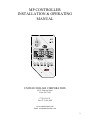
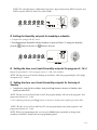
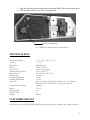
MP CONTROLLER The MP Controller is no longer offered by United CoolAir. The manual included here is for reference on those units that have included this controller in the past. Please contact a United CoolAir distributor for alternative controls that would be suitable for your specific application. UNITED COOLAIR CORPORATION 491 E. Princess Street York. PA 17403 (717) 843-4311 Fax (717) 854-4462 www.unitedcoolair.com Email: [email protected] MP CONTROLLER INSTALLATION & OPERATING MANUAL UNITED COOLAIR CORPORATION 491 E. Princess Street York. PA 17403 (717) 843-4311 Fax (717) 854-4462 www.unitedcoolair.com Email: [email protected] 2 TABLE OF CONTENTS GENERAL INFORMATION 3 MP CONTROLLER COMPONENTS Main Board Temperature / Humidity Sensor Display Display Layout Normal Display Mode 3 3 3 4 4 5 INSTALLATION OF THE COMPONENTS Installation of the Display Location Installation Materials and Tools Installation Procedure Installation of the Temperature / Humidity Sensor Location Installation Materials and Tools Installation Procedure 6 6 6 7 7 7 7 7 7 OPERATION OF THE CONTROLLER General Notes Starting and Turning Off Unit Mode Setting Current Temperature Set Point Setting Current Humidity Set Point Humidity Override Dehumidification / Reheat Auto Fan 8 8 8 8 8 9 10 10 10 MP CONTROLLER ALARMS Alarm Type Alarm Reset 10 10 11 PROGRAMMING THE CONTROLLER General Notes A. Setting the Time Of the Day / Day of the Week B. Setting the Time of Program for Weekdays Schedule C. Setting the Cool / Heat Set Point for Weekdays Schedule D. Setting the Humidity Set Point for Weekdays Schedule E. Setting the Time, Cool, Heat and Humidity Set Points for Programs 2, 3 and 4 F. Setting the Time, Cool, Heat and Humidity Set Points for Saturday & Sunday Schedule 11 11 11 12 12 13 13 13 14 CARE AND MAINTENANCE General Care Battery Care 14 14 14 SPECIFICATIONS 15 CUSTOMER SERVICE 15 3 GENERAL INFORMATION Read and save this installation and operating manual before proceeding with installing or operating the MP CONTROLLER. 1. The MP CONTROLLER has been carefully inspected and tested before leaving the factory. 2. Examine the controller components (SENSOR and DISPLAY units) for any damage that might have occurred during transit. Please notify the carrier if there is any damage. 3. Installation of the MP CONTROLLER should be performed by qualified personnel. THE MP CONTROLLER COMPONENTS The MP CONTROLLER is made up of three components. MAIN BOARD The MAIN BOARD (Fig 1) is an electronic component located inside an electrical box of the unit. It controls all the functions of the compressors, fans, humidifier, etc. Only qualified personnel should access the board. Temperature / Humidity SENSOR The Temperature/ Humidity sensor (Fig 2) is wall mounted. The sensor measures the temperature and humidity of the conditioned space and provides the controller with the data for the control actions. Fig 1 Main Board Fig 2 Temperature / Humidity SENSOR 4 Display The display (Fig 3) provides information on the state of the controller. It also serves as the interface for controlling the operating parameters. Fig 3 Display Display Layout 11 2 12 3 1 10 13 7 4 8 5 9 6 Fig 4. DISPLAY 5 1. ON/OFF button: Press to turn the unit on. Press and hold for about 3 seconds to turn the unit off. 2. button: Press this button to increase the value of the control parameter when the cursor is in a parameter field. 3. button: Press this button to decrease the value of the control parameter when the cursor is in a parameter field. 4. PROG button: Press this button to go to the program mode of the controller (the LCD will flash). 5. CLOCK button: Press this button to adjust the time and day of the week. The +/– buttons are used to carry out the adjustment. 6. MODE button: Pressing this button sets the operating mode: COOL only, HEAT only, COOL/HEAT (auto change over) or FAN ONLY. 7. HUM button: This button controls the humidifier function while the unit is in operation. It is also used to change the humidity set point for the current program cycle. 8. RESET button: Pressing this button will reset the controller after an alarm. 9. AUTO FAN button: Pressing this button activates the auto fan mode, thus the indoor fan will only come on when there is a call for heating or cooling. When the controller is not on AUTO FAN, the indoor fan will be on all the time. 10. LCD DISPLAY : The liquid crystal display. The user will view the controller actions via this display. 11. ON LED: Green LED indicates the state of the unit. When lighted (ON constantly), unit is running, when blinking, unit is on standby. 12. ALARM LED: Red LED indicates an alarm condition. When blinking, there is an alarm. It will remain blinking until the system is reset. 13. DRY: Above this location, the LCD Display will indicate when the system is in the dehumidification mode. Normal display mode Whenever the controller is on, the display will alternatively show the following: • The time of the day. • The set temperature for the particular period. • The current room temperature. • The current room humidity (if humidifier is on). 6 INSTALLATION OF THE COMPONENTS NOTE: The Main Board (Fig 1) is factory installed and is located inside the unit. The procedure for field installation of the display and sensor is as indicated below. Installation of Display The display has an electronic circuit board housed in a 2-piece plastic container. The top piece has the display LCD while the bottom piece has the circuit board and the 3 screw positions for attaching the display to the wall. The two pieces are connected using a pop-up hook, to open, use a small flat screwdriver to push the hook inwards and then lift the top piece. (See Fig 5) CAUTION: Do not apply excessive force on the hook! It may damage the locking capability of the case. TOP PIECE Bottom piece attached to the wall. Pop-up hook for display cover Fig 5 OPENED DISPLAY SHOWING POP-UP HOOK Location The display can be located up to 300 ft (total wire length) from the main board. In selecting a location for the display, take note of the following: The display should not be exposed to direct sunlight or moisture. Display should not be located near electrical appliances (i.e.: microwave oven). The display does not have to be in the conditioned space. 7 Installation materials and tools 4-conductor 18-guage shielded wire (field supplied) Small straight screwdriver. Power drill and drill bits. Set of three (3) screws suitable for the wall material (field supplied). Installation procedure Step 1. Open the display case. Step 2. Remove the top piece. (See Fig 5). The top piece LCD is connected to the board with a ribbon cable that can be separated by gently pulling on the plug at the board. Step 3. Mark the location points for the display wall attachment. Step 4. Attach the bottom piece to the wall using the three screws. Step 5. Run the shielded connection wire from the display to the controller (300 ft. max.). NOTE: Avoid high power lines as much as possible. Step 6. Connect the display and the controller in accordance to the wiring diagram supplied with the unit. Step 7. Reinstall the top piece and snap into position. Installation of Temperature / Humidity Sensor The sensor can be located up to 300 ft (total wire length) from the main board. Ensure that: It is free of any object or interference It is NOT near moisture or direct sunlight. It does NOT have a heat source directly below it. It is NOT located directly in the air stream of the supply diffuser. It is NOT subject to vibration. The height above the floor is approximately 5 feet. Installation materials and tools 6-conductor 18-guage shielded wire (field supplied). Small straight & Philips screw drivers. Power drill and drill bits. Set of two (2) screws suitable for wall material (field supplied). Installation procedure Step 1. Open the sensor cover using a Philips screwdriver. Step 2. Remove the cover. Step 4. Mark the location points for the sensor wall attachment. 8 Step 5. Attach the bottom piece to the wall using the two screws. CAUTION: Make sure sensor is positioned in the proper orientation per the label on the cover. The air path over the sensors is critical to proper functioning. Mounting the sensor in an incorrect orientation may result in erratic operation. Step 6. Run the shielded connection wire from the sensor to the controller. NOTE: Avoid high power lines as much as possible. Step 7. Connect the sensor and the controller in accordance to the wiring diagram supplied with the unit. Step 8. Reinstall the cover. OPERATION OF THE CONTROLLER General Notes 1. The MP CONTROLLER has been factory programmed, thus the unit can function immediately after installation. The factory program can be modified. To do this, refer to the PROGRAMMING section of this manual. 2. While unit is ON or standby, it will display the current temperature, temperature set point and current humidity if the humidifier function is turned on. 3. When the system is operating, the green ON LED will be on. While in the standby mode, the green ON LED will blink. Starting & Turning Off Unit 1. Press ON/OFF button to turn unit on. 2. Press ON/OFF button and hold for 3 seconds to turn unit off. Mode You can set the unit to any operational mode desired and in any sequence. It can be on COOL, HEAT or COOL/HEAT or FAN ONLY. 1. Press Mode button to set unit to COOL. 2. Press Mode button again to set unit to HEAT. 3. Press Mode button again to set unit to COOL/HEAT (auto change over) NOTE: The MP Controller display cursor will blink on the current active mode. Setting Current Temperature Set Point You can change the current temperature set point of COOL or HEAT while in standby or operation. NOTE: Any temperature set-point change in the standby or operation mode will ONLY be active through the current program cycle. 9 COOL or HEAT Mode 1. In either mode, press the button to increase or button to decrease the temperature set point of the active mode. The display will change the set point of the active COOL or HEAT mode. 2. After setting the desired temperature, wait for 3 seconds for the controller to accept the new setting and return to the normal LCD display. COOL/HEAT Auto Change Over Mode 1. Press the mode. button to increase or button to decrease the temperature set point of the active 2. After setting the desired temperature, wait for 3 seconds for the controller to accept the new setting and return to the normal LCD display. 3. The display will automatically display the inactive mode set point. 4. Press the button to increase or operation mode. button to decrease the temperature set point of the inactive 5. After setting the desired temperature, wait for 3 seconds for the controller to accept the new setting and return to the normal LCD display. 6. The controller will automatically select the operation mode depending on the settings. Setting Current Humidity Set Point In order to set a current humidity set point, the unit must have a humidifier and the humidifier function has to be activated. 1. Press Hum button and the display will show “yes” or “no”. “Yes” means the function is turned on, while “No” means the function is turned off. 2. If the display indicates that the humidifier function is turned on proceed to step three. If the display indicates that the humidifier function is turned off, press the function. button to activate the humidification 3. Press Hum again, the wall display will show the current humidity set point. 4. Press the desired level. button to increase or button to decrease the current humidity set point to the 5. Press Hum again and display will show “db” (dead band) “db” means dead band: the setting starts from 1 to a maximum of 6 in increments of 1. It indicates the upper and lower value of humidity about the current set- point at which the controller will NOT control the Humidifier. 10 6. Press Hum again and the display will show the “d” (differential) “d” means the differential: the setting starts from 2.0 to a maximum of 4 in increments of 0.5. It indicates the maximum upper and minimum lower value about the current set-point and dead band setting at which the controller will turn the Humidifier ON or OFF. 7. Press Hum again to return to the normal LCD display. Example: If the humidity set point is 55% and “db” is 3 and “d” is 2.0. This implies that if the humidity reading is between 58% and 52%, the controller will NOT control the humidifier. However, if the reading is above 60%, the controller will turn the humidifier OFF, but if current humidity if less than 50 %, the controller will turn the humidifier ON. In summary, in the humidity range of 50% to 60% there is no control action on the humidifier. Humidity Override 1. Press Hum button. 2. Press the button to inactivate the humidifier. Dehumidification / Reheat The MP Controller contains a built in dehumidification function.When the humidifcation function is activated and the humidity in the space is sensed to be higher than the settings, the cooling cycle will automatically be activated to lower the humidity level. On the display LCD a symbol will appear above “Dry” to indicate that this function has been activated. On units with a heater source (typically electric heat, but can be another source such as a steam coil or hot water coil), if the space temperature drops below the cooling setting, the heat source will be activated to temper or maintain the space temperature. Auto Fan Pressing the AUTO FAN button will toggle the unit between fan and auto fan modes. 1.Press AUTO FAN button, if the display shows AUTO FAN, the unit fan will be ON only when there is a call for cooling or heating. In the stand by mode, the fan will be OFF. 2. Press AUTO FAN button again, to place the fan in the ON mode. The fan will have constant operation at all times. MP CONTROLLER ALARMS The MP CONTROLLER is equipped with 6 alarm indicators. Some of the more common alarms are listed below. Loss of evaporator airflow Drain pan overflow Compressor(s) high/low pressure Dirty Air Filter Check heater. Smoke Detector 11 Your specific unit alarm functions can be determined by looking at the unit wiring diagram. Alarms 1 and 2 are critical alarms. When activated they will shut down the system. The Drain pan overflow alarm will shut down all components except the evaporator blower. Alarms 3 thru 6 are indications only. NOTE: It is possible that more than one alarm can occur. Alarm Reset In the event of an alarm: 1. The alarm (red) LED will start to blink and an audible beeping sound will be activated. 2. Press RESET button, the alarm will be displayed on the LCD by the number definition (1 thru 6). 3. Check the nature of alarm and take corrective action as needed. 4. Press RESET button again to clear the alarm. 5. Except for alarm 5, call a service company to rectify other alarms. PROGRAMMING THE CONTROLLER General Notes 1. The MP CONTROLLER is a 5-1-1 programmable device. Monday to Friday have the same program, while Saturday and Sunday can be programmed differently. There are 4 programs per day. 2. The MP Controller is programmed when leaving the factory. The MP Controller has been factory preset for 74F, 68F and 55% for cool, heat and humidity respectively for all programs. The set points for time, temperature and humidity can be modified using the procedures below. NOTE: If the factory settings of the controller are altered, it is advisable to record the new set points in Table 1. 3. To program the controller start by setting the current day and time using procedure “A” below and follow other procedures in sequence. A. Setting the time of the day / day of the week. 1. Press Clock button, the hour LCD will flash. Press the 2. Press Clock again to set the minutes. Press the or or button to adjust the hours. button to adjust the minutes 3. Press Clock again to set the current day of the week. Press the day. or button to adjust the 4. Press Clock again to leave this setting mode. 12 B. Setting the time of program for weekdays schedule 1. Press the Prog button. Program 1 and the weekdays will appear on the display. Prog Clock Mode Hum Auto Reset Fan 2. Press the Prog button: The hour on LCD will flash. To change the hour, press the or to increase to decrease. Prog Clock Mode Hum Auto Reset Fan 3. Press the Prog button: The minutes on LCD will flash. To change the minutes, press the button to increase or button to decrease. Prog Clock Mode Hum Auto Reset Fan C. Setting the Cool / Heat set point for weekdays schedule. 1. Complete setting B as indicated above 2. Press Prog button: HEAT and the temperature set point will flash on the display. To change the temperature, press the button to increase or button to decrease. Prog Clock Mode Hum Auto Reset Fan 3. Press Prog button: COOL and the temperature set point will flash on the display. To change the temperature, press the button to increase or button to decrease. 13 NOTE: The controller keeps a differential of at least 1 degree between the HEAT set point and COOL set point (HEAT is always less than COOL). Prog Prog Clock Mode Hum Auto Reset Fan D. Setting the Humidity set point for weekdays schedule. 1. Complete the settings in B & C above. 2. Press Prog button: Humidifier and the humidity set point will flash. To change the humidity, press the button to increase or button to decrease. Prog Clock Mode Hum Auto Reset Fan I E. Setting the time, cool, heat & humidity set-point for programs 2, 3 & 4 Repeat the procedure B – D for program events 2, 3 and 4 the weekdays. NOTE: The day cursor will continue blinking on weekdays, while the program display will change in sequence of 2, 3 and 4. F. Setting the time, cool, heat & humidity set-point for Saturday & Sunday 1. Complete the setup for the weekdays, then press Prog button to advance to Saturday; then repeat procedure B-D. NOTE: The day cursor will now blink on SAT; the program display will start from program 1 and progressively move to 2, 3 & 4. 2. On completing Saturday, press Prog button to advance to Sunday and complete procedure B-D. NOTE: The day cursor will now blink on SUN, the program display start from program 1 and progressively move to 2, 3 & 4. NOTE: When in programming mode, you can press Clock button repeatedly to change from weekdays to Saturday, Sunday and out of programming mode. 14 Table 1a Weekly Schedule Program No. Temp Cool Humidity Table 1b Saturday Schedule Time Temp Hour Minutes Heat Cool Humidity Table 1c Sunday Schedule: Time Temp Hour Minutes Heat Cool Humidity Hour Time Minutes Heat 1 2 3 4 Program No. 1 2 3 4 Program No. 1 2 3 4 CARE AND MAINTENANCE General Care To keep the MP CONTROLLER working and looking good, follow these guidelines: Avoid any liquid spill on the display or the sensor. The display or the sensor should not be exposed to direct sunlight or moisture. Never use a strong cleaning agent or abrasive powder, as this can damage the finish. Ensure that only qualified personnel do repair work on the unit, even if the repairs do not involve the MP CONTROLLER Battery Care The DISPLAY has a 3V lithium battery. The procedure for battery replacement is as follows: a. When the LCD displays BATT, the battery needs replacement. b. Open the DISPLAY cover. c. Unplug the DISPLAY ribbon cable from the bottom piece attached to the wall. d. Slightly push the battery against the end spring like support, and then use a straight screwdriver to pop up the battery from the hook. e. Replace with a new battery of the same type. 15 f. Plug the cable back into the board and re-attach the DISPLAY with the bottom piece. g. The controller will have to be fully re-programmed. Battery compartment. Fig 6 DISPLAY showing battery compartment. SPECIFICATIONS Temperature Range Accuracy Differential System Fan Control Ambient Storage Temp. Input Voltage Humidity Set Humidity Dead Band Humidity Differential Alarms (6): Compressor Time Delay Display Programmable Periods / Day Backup 45° F / 90° F (16° C / 31° C) +/- 2° F Smart Sensing 2 Heat / 2 Cool Auto / On (1 Speed) -20° F to 135° F 24 VAC (22 to 28 VAC) 20 to 95% 1 to 6% 1 to 4% Loss of Air Flow, Drain Pan Overflow, Hi / Low Pressure, Dirty Air Filter, Check Heater, (1) Open for Options 3 Minutes °F or °C 5-1-1 4 Battery CUSTOMER SERVICE Any questions on the MP CONTROLLER should be directed to the company that supplied the unit. 16 UNITED COOLAIR CORPORATION 491 East Princess Street York, PA 17403 (717) 843-4311 (877) 905-1111 Fax (717) 854-4462 www.unitedcoolair.com Email: [email protected] Subject to change without notice. Printed in the U.S.A. MPIM (0602) Copyright © by United CoolAir 2007. All rights reserved. Wolf 200 (707) 17