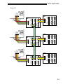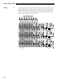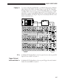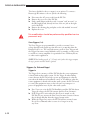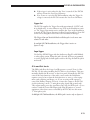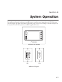
1
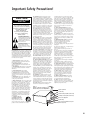
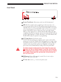
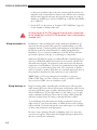
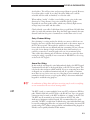
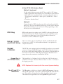
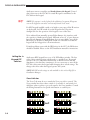
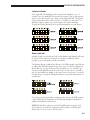
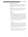
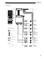
PX-700
Multi-Room
®
Audio Controller
Hardware
Installation Manual
2/2002, rev 2.0
Copyright 2002 Madrigal Audio Laboratories
©
All rights reserved. No part of this publication may be reproduced, stored in a retrieval system, or transmitted, in any form
or by any means, electronic, mechanical, photocopying, recording, or otherwise, without the prior written permission of the
copyright holder.
This publication is designed to provide accurate and authoritative information about the subject matter covered. Audioaccess
reserves the right to make changes without further notice to any products or software herein to improve reliability, function
or design.
Mention of third-party products is for informational purposes only and constitutes neither an endorsement nor a recommendation.
Audioaccess assumes no responsibility concerning the performance or use of these products.
Audioaccess is a registered trademark of Harman International.
NOTE: Due to constant research, the information in this manual is subject to change without notice.
ii
Important Safety Precautions!
End Users: Please read and retain these instructions!
CAUTION
RISK OF ELECTRIC SHOCK
DO NOT OPEN
CAUTION: To prevent electric shock,
do not remove the grounding plug
on the power cord, or use any plug
or extension cord that does not have
a grounding plug provided.
Make certain that the
AC outlet is properly grounded.
Do not use an adapter plug
with this product.
The lightning flash with arrowhead
symbol within an equilateral triangle is
intended to alert the user to the presence
of uninsulated “dangerous voltage” within
the product’s enclosure that may be of
sufficient magnitude to constitute a risk of
electric shock to persons.
The exclamation point within an
equilateral triangle is intended to alert the
user to the presence of important
operating and maintenance (servicing)
instructions in the literature accompanying
the appliance.
Important Note: This product is equipped with
a single pole power switch that disconnects only
the line side of the AC supply. The AC supply is
not completely disconnected from the product
when the power switch is in the off position. To
completely disconnect the AC supply, the power
cord must be disconnected from the AC outlet or
from the rear of the product.
1. Read Instructions. All the safety and
operating instructions should be read before
the product is operated.
2. Retain Instructions. The safety and
operating instructions should be retained for
future reference.
3. Heed Warnings. All warnings on the product
and in the operating instructions should be
adhered to.
4. Follow Instructions. All operating
and use instructions should be followed.
5. Cleaning. Unplug this product from the
wall outlet before cleaning. Do not use liquid
cleaners or aerosol cleaners. Clean only with a
dry cloth.
6. Attachments. Do not use attachments not
recommended by the product manufacturer,
as they may cause hazards.
7. Water and Moisture. Do not use this product
near water – for example, near a bathtub, wash
bowl, kitchen sink or laundry tub; in a wet
basement; near a swimming pool; or the like.
8. Accessories. Do not place this product on
an unstable cart, stand, tripod, bracket or
table. The product may fall, causing serious
injury to a child or adult, and serious damage
to the product. Use only with a cart, stand,
tripod, bracket or table recommended by the
manufacturer, or sold with the product. Any
mounting of the product should follow the
manufacturer’s instructions, and should use
a mounting accessory recommended by the
manufacturer.
9. A Product and Cart
Combination Should Be
Moved with Care. Quick
stops, excessive force and
uneven surfaces may cause the
product and cart combination to overturn.
10. Ventilation. Slots and openings in the
cabinet are provided for ventilation and to
ensure reliable operation of the product and to
protect it from overheating, and these openings
must not be blocked or covered. The openings
should never be blocked by placing the product
on a bed, sofa, rug or other similar surface.
This product should not be placed in a built-in
installation, such as a bookcase or rack, unless
proper ventilation is provided or the manufacturer’s instructions have been adhered to.
11. Power Sources. This product should be
operated only from the type of power source
indicated on the marking label. If you are not
sure of the type of power supply to your home,
consult your product dealer or local power
company. For products intended to operate from
battery power, or other sources, refer to the
operating instructions.
12. Grounding. This product is equipped with
a three-conductor AC mains power cord which
includes an earth ground connection. To prevent shock hazard, all three connections must
always be used. If your electrical outlets will
not accept this type of plug, an adapter may be
purchased. If an adapter is necessary, be sure it
is an approved type and is used properly, supplying an earth ground. If you are not sure of
the integrity of your home electrical system,
contact a licensed electrician for assistance.
13. Power-Cord Protection. Power-supply cords
should be routed so that they are not likely to
be walked on or pinched by items placed upon
or against them, paying particular attention to
cords at plugs, convenience receptacles, and
the point where they exit from the product.
14. Nonuse Periods. The power cord of the
product should be unplugged from the outlet
when left unused for long periods of time.
15. Outdoor Antenna Grounding. If an outside
antenna or cable system is connected to the
product, be sure the antenna or cable system
is grounded so as to provide some protection
against voltage surges and built-up static
charges. Article 810 of the National Electrical
Code, ANSI/NFPA 70, provides information with
regard to proper grounding of the mast and
supporting structure, grounding of the lead-in
wire to an antenna discharge unit, size of
grounding conductors, location of antennadischarge unit, connection to grounding electrodes, and requirements for the grounding
electrode. See Figure 1.
16. Lightning. For added protection for this
product during a lightning storm, or when it
is left unattended and unused for long periods
of time, unplug it from the wall outlet and disconnect the antenna or cable system. This will
prevent damage to the product due to lightning
and power-line surges.
17. Power Lines. An outside antenna system
should not be located in the vicinity of
Figure 1.
Example of Antenna Grounding as per
National Electrical Code ANSI/NFPA 70
overhead power lines or other electric light
or power circuits, or where it can fall into such
power lines or circuits. When installing an outside antenna system, extreme care should be
taken to keep from touching such power lines or
circuits, as contact with them might be fatal.
18. Overloading. Do not overload wall outlets,
extension cords, or integral convenience receptacles, as this can result in a risk of fire or
electric shock.
19. Object and Liquid Entry. Never push
objects of any kind into this product through
openings, as they may touch dangerous voltage
points or short-out parts that could result in a
fire or electric shock. Never spill liquid of any
kind on the product.
20. Servicing. Do not attempt to service this
product yourself, as opening or removing covers
may expose you to dangerous voltage or other
hazards. Refer all servicing to qualified service
personnel.
21. Damage Requiring Service. Unplug this
product from the wall outlet and refer
servicing to qualified service personnel
under the following conditions:
a. The power-supply cord or the plug has been
damaged; or
b. Objects have fallen onto, or liquid has been
spilled into, the product; or
c. The product has been exposed to rain or
water; or
d. The product does not operate normally when
following the operating instructions. Adjust
only those controls that are covered by the
operating instructions, as an improper adjustment of other controls may result in damage
and will often require extensive work by a qualified technician to restore the product to its
normal operation; or
e. The product has been dropped or damaged in
any way; or
f. The product exhibits a distinct change in
performance; this indicates a need for service.
22. Replacement Parts. When replacement parts
are required, be sure the service technician has
used replacement parts specified by the manufacturer or that have the same characteristics as the
original part. Unauthorized substitutions may
result in fire, electric shock or other hazards.
23. Safety Check. Upon completion of any
service or repairs to this product, ask the
service technician to perform safety checks
to determine that the product is in proper
operating condition.
24. Wall or Ceiling Mounting. The product
should be mounted to a wall or ceiling only
as recommended by the manufacturer.
25. Heat. The product should be situated
away from heat sources such as radiators, heat
registers, stoves or other products (including
amplifiers) that produce heat.
Antenna Lead-In Wire
Ground Clamp
Antenna Discharge Unit (NEC Section 810-20)
Grounding Conductors (NEC Section 810-21)
Electric Service Equipment
Ground Clamps
Power Service Grounding Electrode System
(NEC Art. 250, Part H)
iii
Table of Contents
Contents
Page
Important Safety Precautions __________________________________ iii
Typographical Conventions____________________________________ vi
Technical Services ___________________________________________ vi
1
PX-700 Product Description _____________________________________________ 1.1
Description _______________________________________________ 1.1
Features__________________________________________________ 1.2
Inputs ___________________________________________________ 1.2
Outputs _________________________________________________ 1.2
Front Panel _______________________________________________ 1.3
Rear Panel ________________________________________________ 1.4
2
Quick-Start Guide ________________________________________________________2.1
You Will Need ____________________________________________ 2.1
Beginning the Installation ____________________________________ 2.1
Completing the Installation __________________________________ 2.1
Installation Design _________________________________________ 2.1
Connecting the PX-700s _____________________________________2.3
RS-485 Bus _____________________________________________ 2.3
Audio __________________________________________________ 2.6
Paging _________________________________________________ 2.7
IR_____________________________________________________ 2.7
Trigger Out and Switched Outlet_____________________________ 2.7
3
Physical Installation _____________________________________________________ 3.1
Source Equipment AC Power _________________________________ 3.1
Wire Requirements _________________________________________ 3.1
Wiring Information _______________________________________ 3.2
Wiring Warnings _________________________________________ 3.2
Daisy Chained Wiring ___________________________________ 3.3
Home Run Wiring ______________________________________ 3.3
KPT ____________________________________________________ 3.3
KPS Wiring_______________________________________________ 3.4
ATC Wiring ______________________________________________ 3.4
Length of ATC Cable Runs _________________________________ 3.6
Four-Conductor Wiring____________________________________ 3.6
At the ATC Touchscreen Controller _________________________ 3.6
At the ATC RS-232 Interface Board _________________________ 3.7
Method 1 (preferred) ___________________________________ 3.7
Method 2 ____________________________________________ 3.7
iv
TABLE OF CONTENTS
KP3 Wiring_______________________________________________ 3.7
MA-361, VX-241 and PX-603 Wiring __________________________ 3.7
Keypad Installation _________________________________________ 3.7
Keypad Fuse (PX-700 Rear Panel) ____________________________ 3.7
The ATC and KPS IR Receivers _____________________________ 3.7
Setting the Keypad DIP Switches_____________________________ 3.8
Zone Switches __________________________________________ 3.8
System Switches ________________________________________ 3.9
Room Switches _________________________________________ 3.9
DIP Switch Settings for IR _______________________________ 3.10
DIP Switch Settings for Terminator ________________________ 3.10
Final Hookup_____________________________________________3.10
Source Connections ______________________________________3.10
Zone 6 Tape Out ______________________________________ 3.10
Primary Outputs (Variable)_______________________________ 3.10
Expansion Outputs (Fixed) _______________________________ 3.11
IR Outputs ___________________________________________ 3.11
Outputs 1–8 ________________________________________ 3.11
All IR Output _______________________________________ 3.11
Zone Triggers (1–6) ___________________________________ 3.12
Triggers (In, Out and Page) _______________________________3.12
Trigger In ___________________________________________ 3.12
Trigger Out _________________________________________ 3.13
Page Trigger _________________________________________ 3.13
IR In and Out Jacks ____________________________________ 3.13
RS-232 Port __________________________________________ 3.14
Switched Outlet _______________________________________ 3.14
Power Input __________________________________________ 3.14
4
System Operation _______________________________________________________ 4.1
Power ___________________________________________________ 4.2
Volume ▲/▼ ______________________________________________ 4.3
Mute ____________________________________________________ 4.3
Sources __________________________________________________ 4.3
Stop Commands ___________________________________________ 4.3
5
Technical Specifications ________________________________________________ 5.1
Appendix A
Block Diagrams ___________________________________________ A.1
Block Diagram 1 ___________________________________ A.1 & A.3
Block Diagram 2 ___________________________________ A.1 & A.4
Block Diagram 3 ___________________________________ A.2 & A.5
Block Diagram 4 ___________________________________ A.2 & A.6
Addendums
Issued as needed
Separate documentation and .pdf files provided by Audioaccess
v
Typographical Conventions
Please note the following typographical conventions used throughout this manual.
❑
Warnings that relate to user safety are highlighted in BOLD print.
❑
First and second level subsection titles are located in the left margin of each page. Third level titles are
located within the body text and are in bold italic print.
❑
The pointing hand symbol
❑
The lightbulb symbol
❑
Special notes and comments appear in italics. Important terms within a paragraph appear in italics.
❑
When reading this manual as a .pdf document using Acrobat®, clicking on words, sentences or
paragraphs highlighted in blue will transport the reader to the referenced page, section or website.
☞
emphasizes important information within a subsection or paragraph.
emphasizes tips within a subsection or paragraph.
Technical Services
Authorized dealers may obtain answers to questions not covered in Installation Manager Help or in this
Hardware Installation Manual by contacting the technical services department:
Business hours: 8am to 5pm Eastern
Toll Free Audioaccess Service Line:
Phone Sales and Tech Services:
Fax Tech Services:
Email Address:
(888) 691-4171 (USA Only)
(860) 346-0896
(860) 347-6251
[email protected]
Tech Services Web site: http://www.madrigal.com/tech/supportgroup.htm
(User Name: technical, Password: assistance)
These contacts are for Audioaccess Dealers only! Do not supply any of this information to a client.
If you are in the field when you call and reach the auto attendant, press “0” and then ask the operator to
page technical services.
vi
Section 1
PX-700 Product Description
Description
The PX-700 Multi-Room Controller is a six zone, multi-room, multi-source
audio system controller that is easily set up with Audioaccess Installation
Manager, Audioaccess’ proprietary Windows® application. Installation
Manager will program all the functions of a PX-700 installation including
the configuration settings of the MA-361 Twelve Channel Digital Amplifier
and the VX-241 Video Matrix Switcher.
Designed and manufactured by Madrigal Audio Laboratories, the PX-700
audio section delivers the performance associated with high-quality, separate
audio components. The PX-700 chassis fits standard rack-mount shelves.
Together with wall-mounted keypads and handheld remotes, the PX-700
allows direct access and control of eight different audio sources in six separate
Zones. Each Zone can control any five separate sources via the KPS Keypad.
All eight sources are accessible from an ATC Touchscreen Controller and
Audioaccess dedicated remote controls. Up to six PX-700s can be connected
to form a 36-zone installation. Link an unused Zone to another Zone or link
multiple Zones to create a Zone with several Rooms.
The PX-700 is programmed exclusively with Installation Manager, a proprietary Windows® application. With Installation Manager, the installer creates
and maintains a comprehensive Infrared (IR) Library, which is then used to
configure control over the source components in an installation. The IR codes
only need to be learned once for use in all projects. Installation Manager also
allows the installer to define any number of short, long, and remote button
presses, which can be assigned to both the keypads and remotes. Any number
of IR commands can be sent with each press. Because of the open architecture
of the program, multiple high-capacity CD Changers or DSS receivers can
easily be used in a single Installation. IR programming, source assignments,
turn-on source defaults, input level matching, group assignments and other
programming options may be configured prior to the physical installation or
at the job site. Once completed, the project is downloaded to the PX-700 via
an RS-232 input on the rear panel or a convenient PC Link Jack on the front
panel of the controller.
1.1
PRODUCT DESCRIPTION
Installation Manager uses standard control features found in all Windows
applications: right mouse clicks, drag and drop, and pop up menus.
Diagnostic tools are included to monitor RS-485 bus communications.
Other tools include an Equipment List, Wiring Instructions, and a complete
on-line Help file.
Features
❑
❑
❑
❑
❑
❑
❑
❑
❑
❑
❑
❑
❑
❑
❑
❑
❑
Simple, intuitive operation, installation and programming
Component-quality audio performance
Convenient programming via PC or laptop
Built in RS-232 interface accessible from either front or rear panel
Create and maintain an extensive IR Library
Import/export utilities for merging/updating master IR Library
Eight audio inputs plus a paging input for each Zone
Eight sources available from hand-held remotes
Any 5 of 8 sources available from Audioaccess keypads in each Zone
Selectable turn-on source in each Zone
Built-in IR learning device
Zone linking capabilities
Each Zone assignable to one of three All On groups (or none)
Adjustable input levels for each source
Front panel IR receiver, rear panel IR In/Out jacks
Independent bass and treble levels for each PX-700 Room
Expandable to 36 Zones with additional PX-700 Controllers
Inputs
❑
❑
❑
❑
❑
❑
❑
Eight stereo audio inputs with buffered outputs
One mono page input
Trigger input that allows sharing of audio sources with other systems
Four-conductor keypad input
PC Link jack RS-232 interface on front panel
9 Pin D-sub RS-232 interface on rear panel
Rear panel IR input
Outputs
❑
❑
❑
❑
❑
❑
❑
Six buffered preamp outputs (one per zone)
Six fixed outputs
Zone Six record output
Six programmable 12VDC trigger outputs (one per zone)
Nine infrared emitter jacks (one per audio source and blaster)
Trigger output
Rear panel IR output
1.2
PRODUCT DESCRIPTION
Front Panel
SYSTEM CODE SWITCH (Momentary switch accessible through panel)
LED (Bi-color: red when power is applied, green when any zone is on)
The front panel LED on the PX-700 indicates that the unit has power
and that at least one Zone is on in the System. If the LED is on (in any
color), the unit is powered. If the LED is red, no Zones are on in that
System. If the LED is green, at least one Zone is on in the System.
When you first apply power to the PX-700 the LED will be red. After
completing the power-on sequence (about 6 seconds), the LED will turn
green for approximately 5 seconds, then back to red. This indicates that
the PX-700 is ready for operation or programming.
AC POWER SWITCH (Push button switch)
The PX-700 front panel power switch is used to turn on and off the
main power to the unit. With the PX-700 plugged into an outlet, when
the switch is in the IN position, power is applied to the unit. When the
switch is in the OUT position, power is not applied to the unit. The
power state can be determined by looking at the front panel LED.
THE FRONT PANEL POWER SWITCH DISCONNECTS ONLY THE
LINE SIDE OF THE AC SUPPLY WHEN IT IS IN THE OFF POSITION.
TO COMPLETELY DISCONNECT THE UNIT FROM THE AC SUPPLY,
THE POWER CORD MUST BE UNPLUGGED FROM EITHER THE
UNIT OR THE OUTLET.
IR WINDOW (Receives IR commands, controls Zone 6, active only on
System 1. Also used to learn IR)
PC LINK JACK (mono 1⁄8" / 3.5mm mini-phone jack)
1.3
PRODUCT DESCRIPTION
Rear Panel
SOURCE CONNECTIONS (RCA connectors)
PAGE IN/OUT (RCA connectors)
For use with paging systems.
ZONE 6 TAPE OUT (RCA connectors)
IR IN/OUT (mono 1⁄8" / 3.5mm mini-phone jacks)
RS-232 PORT (9-pin female connector)
KEYPAD (4-conductor plug with screw terminals)
FUSE
120V: 5x20mm, 1.6amp, 250v, slow blow
230V: 5x20mm T 1.6amp 250v
POWER INPUT (3-conductor, IEC type)
SWITCHED OUTLET (3-conductor grounded, 300Watt maximum)
TRIGGERS (mono 1⁄8" / 3.5mm mini-phone jacks)
IR OUTPUTS (mono 1⁄8" / 3.5mm mini-phone jacks)
ZONE TRIGGERS (mono 1⁄8" / 3.5mm mini-phone jacks)
EXPANSION OUTPUTS (Fixed) (RCA connectors)
PRIMARY OUTPUTS (Variable) (RCA connectors)
1.4
Section 2
Quick-Start Guide
You Will Need
❑
❑
❑
❑
❑
❑
❑
❑
❑
❑
❑
Beginning the
Installation
• Design the Installation with your client. Determine the source
equipment for the Installation and the way the Installation will work
in each room.
Completing the
Installation
• Wire the Installation.
• Connect the PX-700s to each other.
• Test the Installation. You can test the operation manually from the keypads or remotes, or by using the Virtual Installation in the tools menu.
Installation
Design
The initial steps of the design phase of any Installation begin with planning
measures. Determine how many Zones and total Rooms the Installation
requires and how they will be configured. From this, you will be able to
figure the number of PX-700 Controllers, PX-603 Multi-Room Expanders
and MA-361 Twelve Channel Digital Amplifiers with EM-401
Volume/Tone Control Modules needed in the Installation.
PX-700(s)
KPS(s), ATC(s)
KPT(s)
Amplification
Speakers
Source Equipment
A supply of IR Emitters (not furnished with the PX-700)
4 Conductor Wire
Speaker Wire
Power Strip for source equipment AC power
RCA cables for source equipment connection
2.1
QUICK START GUIDE
☞
The following three conventions apply to Zone and Room definitions:
Zone
A Zone is an area of an Installation that accesses a source independently
from another Zone. A Zone contains a Primary Room and up to three
Expansion Rooms. Each Room within a Zone has independent ON/OFF
and Volume control. There are six Zones available to each PX-700 in
an Installation.
Primary Room
The Primary Room is a specific listening area within a Zone that is fed
signal from the PX-700’s PRIMARY OUTPUTS (VARIABLE). If a single room
is the only room within a Zone, the PRIMARY OUTPUTS are used (see
Primary Outputs on page 3.10).
Expansion Room
Expansion Rooms are listening areas within a Zone that are fed signals
from the PX-700’s EXPANSION OUTPUTS (FIXED). Expansion outputs
are connected to the inputs of the PX-603 Multi-Room Expander or
MA-361 Twelve Channel Digital Amplifier with EM-401 Volume/Tone
Control Modules (see Expansion Outputs on page 3.11).
Determine the number and type of keypads for each Room of the Installation.
The keypads should be optimally located for simple access, taking into consideration the way the clients will use the Installation, environmental concerns,
and ambient lighting conditions. This requires understanding the way natural
light moves across the space during the course of the day as well as the type
and placement of lighting fixtures. The IR receiver on Audioaccess keypads is
sensitive to all forms of light.
Choose the source equipment to be used in the Installation and how it will
be partitioned among Zones. For example, one Zone may make use of a
dedicated tuner.
Select which keypad buttons will control which sources in each Zone. This
may require you to relocate button caps or order custom imprints.
Consider where the "head-end" will be located. Make sure the designer of
the equipment cabinet allows sufficient space for all the equipment, accessories, and access to connections. You will have one or more PX-700s,
source equipment, amplifiers, PX-603 Multi-Room Expanders, cabling
between componnents, and cabling out to speakers, keypads, etc.
2.2
QUICK START GUIDE
The PX-700 must be very well ventilated. Be sure to provide for this when
installing each unit and in designing of any cabinetry for the Installation.
Provide ample space for air circulation and flow-through ventilation around
all the other electronics too, especially amplifiers. Allow room for growth of
the system.
Whenever possible, allow for access to the back of the equipment. This can
be accomplished with pullout cabinets, pullout shelves, or through an
adjoining room or crawl space behind the cabinet.
Request at least a 20 amp, dedicated circuit for the Installation. Consult the
specified current requirements for the equipment and determine the maximum potential current draw. Review this information with the electrician or
engineer on the job to determine the requirement for your circuit.
Connecting the
PX-700s
RS-485 Bus ➤
The PX-700s communicate with each other via the RS-485 bus. Use one
or more KPT Keypad Termination Boards for each PX-700, depending on
the total number of keypads and other Audioaccess equipment in the
System. Once all the equipment is terminated, parallel the Data 1, Data 2
and GND (ground) conductors of each KPT together. Use terminals on the
KPTs for this connection, or if none are available, double up the conductors
on one screw terminal on each KPT (see Examples A and B).
Do not connect the power conductor between PX-700s!
Each PX-700 should power the keypads plugged into its respective KPT
only. Distribute all the keypads evenly between the PX-700s, regardless of
whether they control a PX-700 Zone or Expansion Room. The DIP switch
setting on each keypad determines which System, Zone and Room it controls, but each PX-700 should power an equal number of keypads. The maximum number of keypads per PX-700 is twenty (20). See Important Note
on page 3.5 for details on calculating the maximum amount of ATC
Touchscreen Controllers.
Depicted on the next two pages (in Examples A and B) are two methods to
connect multiple PX-700 units to each other via the RS-485 bus. Both are
electrically identical. However, we have found that Example A provides the
easiest method to isolate and diagnose any RS-485 bus conditions in the field.
Example B provides a single wire connection to each RS-485 connector.
2.3
QUICK START GUIDE
GND
Data 2
Data 1
PWR
Example A
PX-700
Rear
Panel
KPT
P
D1
D2
G
P
P
P
D1
D1
D1
D2
D2
D2
G
G
G
P
P
P
D1
D1
D1
D2
D2
D2
G
G
G
P
P
P
D1
D1
D1
D2
D2
D2
G
G
G
P
P
P
D1
D1
D1
D2
D2
D2
G
G
G
P
P
P
D1
D1
D1
D2
D2
D2
G
G
G
P
P
P
D1
D1
D1
D2
D2
D2
G
G
G
PX-700
Rear
Panel
KPT
P
D1
D2
G
PX-700
Rear
Panel
KPT
P
D1
D2
G
2.4
QUICK START GUIDE
GND
Data 2
Data 1
PWR
Example B
PX-700
Rear
Panel
KPT
KPT
P
D1
D2
GND
Data 2
Data 1
PWR
G
D1
D2
GND
G
Data 2
P
P
D1
D1
D1
D1
D2
D2
D2
D2
G
G
G
G
P
P
P
D1
D1
D1
D2
D2
D2
G
G
G
KPT
P
Data 1
P
PX-700
Rear
Panel
KPT
PWR
P
P
P
P
P
D1
D1
D1
D1
D2
D2
D2
D2
G
G
G
G
P
P
P
D1
D1
D1
D2
D2
D2
G
G
G
PX-700
Rear
Panel
KPT
KPT
P
D1
D2
G
P
P
P
P
D1
D1
D1
D1
D2
D2
D2
D2
G
G
G
G
P
P
P
D1
D1
D1
D2
D2
D2
G
G
G
P
P
P
D1
D1
D1
D2
D2
D2
G
G
G
P
P
P
D1
D1
D1
D2
D2
D2
G
G
G
P
P
P
D1
D1
D1
D2
D2
D2
G
G
G
P
P
P
D1
D1
D1
D2
D2
D2
G
G
G
P
P
P
D1
D1
D1
D2
D2
D2
G
G
G
P
P
P
D1
D1
D1
D2
D2
D2
G
G
G
2.5
QUICK START GUIDE
Audio
2.6
➤
To connect audio sources, use regular RCA cables to connect sources to the
left and right SOURCE IN jacks on the rear panel of the first PX-700. With
additional RCA cables, connect the SOURCE OUT jacks to the SOURCE IN
jacks of the next PX-700. Cascade the Source In and Out in this manner
until you have connected all the PX-700s.
QUICK START GUIDE
Paging ➤
IR ➤
Trigger Out and
Switched Outlet ➤
To connect a Page/Doorbell Module to a multi PX-700 system, parallel the
Mute Out from the PDM to the Page Trigger of each PX-700. To parallel
the Page Trigger, use a two-way 1/8" mono mini plug splitter or "Y" adapter
(available at most electronic supply shops) and an extra mini plug to mini
plug cable to connect each additional PX-700. Connect the Page Audio output from the PDM to the Page In. Page Out is cascaded just like the source
audio as described above.
In Multiple PX-700 Installations, the front panel receiver and rear panel IR
Input are active ONLY on System 1.
In Multiple PX-700 Installations, the rear panel Trigger Out and Switched
Outlet are active ONLY on System 1.
2.7
(this page is intentionally blank)
2.8
Section 3
Physical Installation
Source Equipment
AC Power
Use the Switched Outlet to provide power to source equipment whenever
possible, because the PX-700 needs to power up equipment in a known
state when the Audioaccess Installation comes on. In addition, when the
source equipment is shared with another audio system, the PX-700 needs
to control the equipment status so that it does not stop transports or power
off equipment in use by the other audio system (refer to Switched Outlet
on page 3.14).
Wire
Requirements
Audioaccess products must be interconnected for them to communicate over the
Audioaccess RS-485 bus. Controllers located close to each other (e.g. multiple
PX-700s) can be connected to the RS-485 bus using any type of 4-conductor,
24AWG cable. Keypads and Audioaccess products located more than 250 feet
from the head end have specific cable requirements impacting the number of
conductors required and type of cable used. Follow these guidelines:
1. Use cable constructed of twisted pairs with either stranded or solid conductors. Twisted pairs reduce the effects of electrical noise induced on the
cable by ensuring the noise is ‘common mode’ (the same on both wires of
the pair), and therefore is ignored by the bus transceiver IC. Make sure
the data lines (DATA 1 and DATA 2) are a pair and power and ground
(PWR and GND) are a pair.
2. If you are using only KPS keypads, use cable with 2 pairs. For KP3
keypads, use cable with 3 pairs (see KP3 Wiring). For ATC keypads, use
Cat 5 (4 pair) cable (see ATC Wiring on page 3.4).
3. If your installation is in a high EMI environment (for example, subject to
frequent and/or severe electrical storms or in close proximity to a radio
transmitter), use only shielded, twisted pair cable regardless of the cable
length. For shielded cable to be effective, connect all shields together at
the head end and tie to earth ground (use one of the zinc plated [silver]
screws on the rear panel of the Controller near the Keypad connector).
The shield should not be connected at the keypad. Long outdoor runs of
cable should be in earth-grounded metal conduit.
4. Use cable with a wire gauge appropriate to the length of cable run from
the keypad (or product) to the Controller. There will be a voltage drop
3.1
PHYSICAL INSTALLATION
on the power conductors due to the wire resistance and the current consumption of the connected device. Heavier wire will have lower resistance,
therefore the longer the wire run, the lower the wire gauge. As a rule of
thumb, use 24AWG up to 250 feet, 22AWG up to 500 feet and 20AWG
up to 1,000 feet.
5. For the ATC, see the section on “Length of ATC Cable Runs” (page 3.6)
for the formula to calculate cable runs.
In North America, UL/CSA requires that all wires connected
to the RS-485 bus on the PX-700 be rated Class II and surface
marked VW-1.
Wiring Information ➤
In addition to audio switching and routing, Audioaccess Installations are
data network control systems that operate in a similar fashion to an office
computer network. Consistent polarity and termination of the Audioaccess
RS-485 bus is the most critical element in a reliable and problem-free
Installation. Loose or incorrect terminations of the RS-485 bus will cause
inconsistent operation, lock ups, or even damage to components.
Audioaccess Installations operate on standard RS-485 communications at a
data rate of 9600 baud. An RS-485 transceiver is located in each PX-700
and Audioaccess keypad. The transceiver sends and receives data between
components of an Installation. The four-wire communications bus includes
one power, one ground, and two data wires. The connections of all these
wires are sensitive to polarity. If the lines are connected improperly, there is
the potential for destruction of the transceivers in any component.
NOTE: Make sure all wiring throughout the Installation is consistent:
PWR to PWR, Data 1 to Data 1, Data 2 to Data 2, and GND to GND.
Any inconsistency WILL cause the Installation to fail.
Wiring Warnings ➤
Keep low-voltage cables, especially audio and data wires, well away from
cables carrying AC house current, all antennas, and television cable. If your
wire must parallel these types of cables, maintain at least 12" of separation
and use shielded wire. If your cables must cross AC cables, cross at a right
angle to minimize interference. Never run low-voltage cables though the
same hole as high-voltage AC wiring or through the same conduit.
To avoid damage from nails and screws during construction, keep your
cables at least 2" away from the surface on which the sheet rock or plaster
will be attached. Use metal nail guards in areas where space is not available
or where extra precaution seems appropriate.
Be aware of any remaining electrical or plumbing work to be done after
your wires are in place. Protect them accordingly and inspect them before
they are covered by the wall surface.
3.2
PHYSICAL INSTALLATION
Avoid splices. This will save time and prevent problems in general. However,
if you must splice a cable, do not bury the splice! Make sure it will be
accessible after the walls are finished, or re-run the cable.
When making “trunks” of cables (several cables groups going in the same
direction for a long distance), keep wires with like signals together.
Especially be sure that speaker cables, which carry relatively high current,
are kept away from audio and data cables.
Clearly identify your cables. Label them when you pull them. Re-label them
when you trim and terminate them. Keep the labels approximately the same
distance back from the point of termination to make them easier to read.
Daisy Chained Wiring
Daisy chaining is a wiring method in which you connect a cable from one
keypad to the next, with the final termination made to the KEYPAD input on
the PX-700 rear panel. This method is suitable for retrofitting existing
homes where home runs are difficult and time consuming. In new construction, risk of wire damage is high, and with the daisy chain method, you
could lose connection to many keypads with one non-terminated point.
Thus, while daisy chaining may be efficient, absolutely use extra care when
routing the wiring, especially in new construction. DO NOT use this wiring
method with ATC keypads.
Home Run Wiring
In this method, each keypad is wired independently back to the KPT Keypad
Termination Board, then to the keypad input on the PX-700 rear panel. This
is by far the safest and most reliable method. If you are connecting more than
six keypads, use an additional termination board. It is possible to terminate
more than one set of wires onto any one of the plug-in screw terminals on the
termination board, however you give up the ability to disconnect individual
keypads for troubleshooting purposes.
☞
KPT
A combination of daisy chain and home run wiring may be used in retrofitting
or new construction. Be sure to heed warnings above.
The KPT is used to connect multiple, home run ATC touchscreens, KPS keypads, PX-603s, MA-361s and VX-241s to the RS-485 bus. Up to six separate
connections may be made to the KPT in addition to a jumper to the PX-700.
The KPT may be mounted in any location between the PX-700, other
Audioaccess equipment, and the keypads. We recommend that it be easily
accessible. The KPT is useful when troubleshooting, since individual lines may
be tested by unplugging all but the one in question. Mis-wiring, incorrect DIP
switch settings, ATC address setting problems, and malfunctioning keypads or
PX-603s can be quickly identified in this manner.
3.3
PHYSICAL INSTALLATION
In multiple PX-700 Installations, each PX-700 in the Installation should
have a dedicated KPT so that the keypads are not all powered from the
same unit (see Examples A and B on pages 2.4–2.5).
KPS Wiring
The wiring code (Power, Data 1, Data 2, and Ground) is shown on both the
back plate of each keypad and on the rear panel of the PX-700. Some keypads have a color code on the back plate that you may choose to follow. Be
certain to follow EXACTLY the same wire code for all connections. Power
and ground should be one twisted pair, and data should be the other. All four
conductors must be connected to the keypad. To avoid shorting, do not leave
any of the wires disconnected or twisted together. The screw terminals must
make connection with bare wire, so be certain that none of the insulation on
the wires is caught in them.
☞
ATC Wiring
IMPORTANT: Terminate the cable on the keypad first, then the KPT and then
PX-700. This is the best way to avoid blowing the keypad fuse on the PX-700.
(See Wiring Information for more details.)
An ATC Touchscreen Controller installation requires both the ATC and one
ATC RS-232 Interface Board per ATC with one exception as noted below
under “Four Conductor Wiring.”
1. Install the ATC RS-232 Interface Board at the head end of the
Installation (the equipment end).
2. Pull Cat 5 cable from the ATC location to the head end.
3. Terminate both ends of the Cat 5 cable with RJ-45 8 pin connectors (for
short runs or programming on the bench, you may use standard Ethernet
cable available at any computer supply store). It is critical that you pair
the Cat 5 cable wires as follows and that both ends of the cable are wired
identically:
• Pins 1 and 2 (RXD + and -)
• Pins 4 and 5 (RS-485 – [data 2] and + [data 1])
• Pins 3 and 6 (power and ground)
• Pins 7 and 8 (TXD + and -)
This pin number pattern is looking down at the flat side of the connector
(not the side with the locking tab). Make sure the colored pairs are the
same at both ends of the cable.
3.4
RXD +
Data 2
RXD –
Data 1
Power
Ground
TXD +
TXD –
PHYSICAL INSTALLATION
8 7 6 5 4 3 2 1
Front
Top
Ca
t5
C able
C
t
a
5
ble
Ca
4. Connect the Cat 5 cable to the ATC RS-232 Interface Board and the
rear of the ATC.
5. Run 4-conductor wire from the keypad connector on the ATC RS-232
Interface Board to the appropriate keypad connector on a KPT.
☞
IMPORTANT NOTE: The PX-700 is designed to power up to 20 KPS keypads
at 50mA each (to a total of 1A). The ATC keypad draws 150mA, equivalent to
three (3) KPS keypad loads. Therefore, to determine how many ATCs and KPSs
can be powered from any one PX-700 in an Installation, add the number of
KPS keypads times one (1) plus the number of ATC keypads times three (3). The
total may not be greater than 20. If the total is higher, you will need to power
some number of ATC keypads from AC to DC adapters to reduce the number of
keypads powered by the PX-700 to 20 or less.
3.5
PHYSICAL INSTALLATION
Length of ATC ➤
Cable Runs
The resistance of the cable and the voltage of the power supply to the ATC
determine the maximum cable length. The ATC requires a minimum of
8VDC at the ATC. The PX-700 supplies 10VDC from the RS-485 bus. This
means that up to 2 volts can be dropped due to the resistance of the cable. If
the ATC is powered from a PX-700 and your cable has a nominal resistance
of no more than 26Ω/1,000 ft, the cable run should be no more than
approximately 250 feet from the ATC to the ATC RS-232 Interface Board.
If you require a cable run of more than 250 feet, you must either use CAT
5 cable with a resistance of less than 26Ω/1,000 ft, or use an AC to DC
adapter that provides a voltage higher than 10VDC. If the ATC is powered
from a 12VDC AC to DC adapter and your cable has a nominal resistance
of no more than 26Ω/1,000 ft, the cable run should be no more than
approximately 500 feet from the Interface Board.
If your Cat 5 cable has a resistance other than 26Ω/1,000 ft, use the formula
below to figure the maximum length of your cable run or to determine the
appropriate supply voltage for a specific cable length.
Supply Voltage (from PX-700 or adapter) – 8
X (length of cable run) = ___________________________________________ x 1000
.3 x (Ω /ft rating of cable)
Four-Conductor ➤
Wiring
If you have already run 4-conductor cable to the ATC location, you have two
choices. You can replace the 4-conductor with Cat 5 and connect the ATC as
described above, or you can install the ATC with the 4-conductor cable.
NOTE: If you choose to use only 4-conductor cable, you cannot use the RS-232
port (D connector) at the ATC RS-232 Interface board. The ATC will work as
a touch screen with all menus, but you will not be able to use it to control other
systems, nor will you be able to program it after it is installed from the Interface
Board. The ATC must be programmed prior to installation.
At the ATC Touchscreen Controller
1. Make a pigtail with a short length of Cat 5 and an RJ-45 8 pin
connector, wired as described above.
2. Splice this to the 4-conductor cable, connecting only power (pin 3),
ground (pin 6) and RS-485 + /data 1 (pin 5) and RS-485 – /data 2
(pin 4).
3. Connect to rear of ATC.
3.6
PHYSICAL INSTALLATION
At the ATC RS-232 Interface Board
Method 1 (preferred)
Use this method when powering the ATC from an AC to DC adapter.
1. Make a pigtail with a short length of Cat 5 and an RJ-45 8 pin connector.
2. Splice this to the 4-conductor cable, connecting only power (pin 3),
ground (pin 6) and RS-485 + /data 1 (pin 5) and RS-485 – /data 2
(pin 4).
3. Connect to Interface Board.
Method 2
Connect directly to KPT, using the same cable run formula as for Cat 5
cable above. If you use this method, make sure you have an ATC RS-232
Interface Board with you at the job-site for ATC programming, as there
will not be one in the Installation.
KP3 Wiring
KP3 keypads require six-conductor wire (24 AWG), and must be home run
directly to the back of the PX-603. Terminate wire ends with RJ11 six-pin,
six-conductor modular plugs. See the PX-603 Installation Manual for
instructions as well as an illustrative diagram.
MA-361, VX-241
and PX-603 Wiring
The four-conductor bus of each MA-361, VX-241 and PX-603 should
be home run to a KPT. See the Installation Manual of each product for
complete instructions.
Keypad
Installation
The PX-700 comes equipped with one detachable 4-conductor screw terminal
connector. Connect a single KPS keypad, an ATC RS-232 Interface board, or
the last leg of a KPS daisy-chained cable to this connector. If keypad cables are
home run, connect them to a KPT Keypad Termination Board, then run a
jumper between the termination board and the PX-700.
Keypad Fuse ➤
(PX-700 Rear Panel)
The keypad fuse is a 5x20mm, 1.6A, slow blow fuse (230 Volt units use a
5x20mm T 1.6A fuse). This fuse will blow if there is a short or overload on
the keypad power line.
NOTE: Replace this fuse only with the correct type and rating.
The ATC and KPS ➤
IR Receivers
The IR receiver on Audioaccess keypads is NOT an IR repeater. A repeater
takes any IR signal (light), converts it to electrical signals and sends it down a
wire. That signal is converted back into light through an infrared emitter.
The Audioaccess Keypad IR receiver takes specific IR signals from the
3.7
PHYSICAL INSTALLATION
Audioaccess remote controllers and decode them at the keypad. Control
data is then sent to the PX-700. No actual IR signal is transmitted to the
PX-700 from the keypad.
☞
NOTE: If a repeater is needed, plan for the addition of a separate IR repeater
next to the keypad or somewhere conveniently located in the room!
For KPS keypads installed outside or in bright rooms, turn off the IR receiver
on the keypad. Set DIP switch #9 on the keypad in the UP position.
Sunlight can slow the operation of the keypad or act as false data.
Noise radiated from manually operated light dimmers also interferes with
the operation of Audioaccess keypads. Maintain at least 4" of space between
keypads and dimmers. If installing them closer is unavoidable, turn off the
IR receiver on the KPS by lifting DIP switch #9. A metal box around the
keypad will also help protect it from interference.
If similar problems occur with the IR Receiver in the ATC, the IR Receiver
should be disabled. Please see the ATC Installation manual for instructions.
Setting the ➤
Keypad DIP
Switches
Audioaccess KPS keypads have a set of 10 DIP address switches. The first
eight of these switches assign each keypad to a specific Zone, Room and
System Code. Two additional switches turn on the IR receiver and add
impedance to the data lines (terminator). It is not necessary to turn off the
PX-700 or disconnect the keypad while changing these switch settings. The
changes take effect when the keypad operates the system.
NOTE: All DIP switch settings are also available in the on-line Help file in
Installation Manager.
Zone Switches
The Zone Code must be set to match the Zone you wish to control. The
Zone switches have these values: switch 1=1, switch 2=2, and switch 3=4.
Add these values together to get totals equal to the Zone numbers. Consult
the Wiring Instructions for specific information on each Project.
3.8
PHYSICAL INSTALLATION
System Switches
For a single PX-700 Installation, the System Code should be set to “1”
(switch 5 up). In a multi PX-700 system, the System Code on the keypads
must be set to the System Code of the corresponding PX-700. The System
Code switches have these values: switch 5=1, switch 6=2, and switch 7=4.
Add these values together to get totals equal to the System numbers.
Consult the Wiring Instructions for specific information on each Project.
Room Switches
Switches 4 and 8 set the Room Code for the Primary and Expansion Rooms
in a Zone. Their values are: switch 4=1, switch 8=2. Add these values
together to get totals equal to the Room number.
The Primary Room is addressed as Room 0. Set DIP switches 4 and 8 down
to address the PX-700 Primary Room of the Zone. For the first Expansion
Room added to a Zone, the Room Code should be set to 1 (switch 4 up).
For the second added Room in the same Zone, set the code to 2 (switch 8
up). For the third Room added to the same Zone, set the code to 3 (switches 4 and 8 up). Consult the Wiring Instructions for specific information on
each Project.
Zone, Room and System address settings are the same for the DIP switches
on the PX-603 Room Expander (see the PX-603 Installation Manual for
additional installation instructions).
NOTE: PX-603 Rooms that are controlled by KPS keypads must have both
the PX-603 rear panel Room Configuration DIP switches and KPS keypad
DIP switches set in the manner described above.
3.9
PHYSICAL INSTALLATION
DIP Switch Settings for IR
Switch #9 controls the keypad IR receiver. In the “down” position it is ON,
in the “up” position it is OFF. When a keypad is mounted outdoors, in a
bright, sunny room or within 4" of a manually operated light dimmer, the
IR receiver should be turned off.
DIP Switch Settings for Terminator
Switch #10 controls the terminator. This switch adds 1K ohm impedance
across the two data lines. Keypads are shipped with the terminator switch in
the “up” or OFF position. In daisy chain keypad installations, terminate the
keypad furthest away from the PX-700 by setting the switch in the “down”
or ON position. In a home run keypad installation, terminate the keypad on
the longest run. One keypad should be terminated in each System in multiPX-700 Installations. If a keypad exhibits unusual behavior such as slow
response to button presses, change the terminator position on that keypad.
Final Hookup
Source ➤
Connections
During final hookup, install and connect the PX-700, amps, source equipment and all other equipment following the Wiring Instructions from
Installation Manager. The PX-700 may be rack mounted, using a thirdparty rack shelf. The unit stands slightly more than two rack-spaces high; it
should be installed in three spaces to ensure adequate ventilation.
The Source In and Page In have corresponding buffered Outs for connecting
sources to multiple PX-700s or to other systems which share the same sources
(e.g. surround-sound processors or other receivers). Plug in RCA-type audio
cables from the source equipment to the Source Ins on the rear panel.
Zone 6 Tape Out
Connect this output to the input of the tape deck used for recording. The
source signal selected in Zone 6 is routed to this output. Connect the Tape
Out to the RECORD IN of the tape deck if one is used. You can also use this
output as an additional expansion output for Zone 6.
NOTE: The Tape Out does not prevent a feedback loop when listening to and
recording from the same source.
Primary Outputs (Variable)
There is one stereo preamp output per Zone. These variable outputs are
controlled from the keypads and IR remotes. Connect the PRIMARY OUTPUTS
(VARIABLE) to amplifiers used to power the Primary Room of the Zone.
3.10
PHYSICAL INSTALLATION
Expansion Outputs (Fixed)
These are secondary, fixed, unity gain outputs for each Zone which are
specifically designed for connection to an MA-361 Twelve Channel Digital
Amplifier with up to six EM-401 Volume/Tone Control Modules or a
PX-603 Multi-Room Expander. Up to three Expansion Rooms may be
added to any Zone.
Expansion Outputs may also be used as fixed outputs to an amp that powers
speakers through passive attenuators (autoformers). The output signal is
determined by the source selected in the Zone. Signal is present at the
EXPANSION OUTPUT any time the corresponding Zone is on.
IR Outputs
Outputs 1-8
Audio sources connected to the PX-700 are controlled by IR commands
taught to the PX-700. Source specific IR OUTPUTS for each of eight audio
inputs allow multiple tuners, CD players or tape decks of the same brand
to be controlled independently. IR commands are sent to the sources
either via a 1⁄8" mono mini-plug from the IR Out to an IR input jack on
the source equipment or through an IR emitter attached to the IR receiver
on the source. This is necessary when more than one source uses the same
IR command set. The jacks are source specific; only the IR commands
programmed in the Source 1 button press, for example, will play through
IR OUT 1 (or as designated in Installation Manager).
NOTE: Use any emitter compatible with a 9-12VDC output.
All IR Output
The ALL IR Output transmits all the IR information transmitted by any
other IR Output. The jack marked ALL may be connected to a blastertype IR output device for control of multiple sources. Or, you may use
it with a 1⁄8" mini-plug to control source components which have optoisolated IR input and output jacks on their rear panels. When using these
components, connect the output of the ALL jack to the IR input on one
component then out to the next one in the stack. Cascade from one
source to the next until all are connected.
NOTE: The cascaded connection described above will not allow independent
control of multiple sources of the same type. These must be connected to the
rear panel jacks using separate emitters from each source specific IR OUTPUT.
Connect an emitter for each source controlled by the PX-700.
3.11
PHYSICAL INSTALLATION
The factory default for the ALL output is as an emitter. To connect a
blaster-type IR emitter to the ALL jack do the following:
➤ Disconnect the AC power cord from the PX-700
➤ Remove the top cover of the PX-700.
➤ Find a small jumper with the words “FLASHER” and “BLASTER” on
the IR Output board, directly in front of the ALL jack at the right
end of the PCB.
➤ Remove the shorting plug and place on the side marked “BLASTER”.
➤ Replace the cover.
This modification should be performed by qualified service
personnel only!
Zone Triggers (1-6)
The Zone Triggers are programmable to provide a constant 12VDC
voltage through each output any time the zone is on or only when the
Primary Room is on. The total load current on all six Zone Triggers and
the Trigger Out cannot exceed 200mA total. For example, you may want
to switch on a remote amplifier for a particular Zone or Primary Room,
or other creative application.
NOTE: When hooking up the 1⁄8" (3.5mm) mini jack to the trigger outputs,
the tip is positive and the shield is ground.
Triggers (In, Out and Page)
Trigger In
The Trigger In is a means to tell the PX-700 that the source equipment
is shared with another audio system. Use the Trigger In when sharing
sources because the PX-700 needs to power up equipment in a known
state when the Audioaccess Installation comes on. In addition, when the
source equipment is shared with another audio system, the PX-700 needs
to control the equipment status so that it doesn’t stop transports or
power off equipment in use by the other audio system.
➤ If no Zones are on in the PX-700 Installation and the PX-700 detects
Trigger In voltage, the PX-700 executes the First Zone On macro.
➤ If the Trigger In is active when the first Zone is turned on, the
PX-700 does not execute the First Zone On macro, because it knows
that it already did that when the trigger became active.
➤ While the Trigger In is active, the PX-700 will not execute Source
Not in Use commands when a source is no longer in use by
any Zone.
3.12
PHYSICAL INSTALLATION
➤ If the trigger is active when the last Zone is turned off, the PX-700
will not execute the Last Zone Off macro.
➤ If no Zones are on in the PX-700 Installation when the Trigger In
voltage is removed, the PX-700 executes the Last Zone Off macro.
Trigger Out
The PX-700 supplies the Trigger Out with approximately 12 VDC and,
in its default state, is active whenever any Zone in the Installation comes
on. The Trigger Out remains active until the last Zone in the Installation
is turned off. The Trigger Out state for First Zone On and Last Zone Off
events can be changed on the Events Tab in Installation Manager.
The Trigger Out and Switched Outlet will always be in the same state
relative to each other.
In multiple PX-700 Installations, the Trigger Out is active on
System 1 only.
Page Trigger
Use the Page (PDM) Trigger with the Audioaccess Page/Doorbell Module
or other paging system. When this jack is shorted, all Zones programmed
to receive paging and doorbell signals switch to the Page In until the jack is
un-shorted.
IR In and Out Jacks
The IR In jack allows hook up of an IR repeater to control Zone 6 of the
PX-700. Use this when installing the PX-700 in a closed cabinet. This automatically disables the IR receiver on the front panel. Normally, the PX-700
controls the basic functions of the audio sources unless the Installation
requires control of more than the basic functions or access to other equipment such as lighting and drapes, etc. If you are using an IR repeater to
control the Primary Output of Zone 6, connect the output to the PX-700
via this jack using a mono 1⁄8" mini phone plug (signal and ground only).
This output merely passes the signal that comes into the IR In jack – do not
confuse it with the Source IR Output jacks. Plug IR emitters to control
equipment (other than sources controlled by the PX-700) into this mono
1⁄8" mini phone jack.
In Multiple PX-700 Installations, the IR In jack is active only on System 1.
3.13
PHYSICAL INSTALLATION
RS-232 Port
This port enables direct connection of other RS-232 command systems to
the PX-700 or connection to a PC for IR and system programming. The
programming port is replicated with a mini-jack on the front panel. When
the front panel PC Link is in use, the rear panel connector is inactive.
Switched Outlet
This outlet powers up when the first Zone is turned on, and off when the
last Zone is turned off according to the programming of the Trigger Out in
Installation Manager. Plug a power strip into this outlet then plug the
source equipment into the power strip (300 watts maximum).
WARNING: Do not use this outlet with amplifiers or any combination of components that draw more than 300 watts! The
switched outlet is internally fused. Replace fuse only with the
same type and rating. The PX-700 should be serviced by
qualified service personnel only.
In multiple PX-700 Installations, the Switched Outlet is active only on
System 1.
Power Input
The power input is a standard IEC type 3-prong male connector. Connect
the AC power cord to the rear panel of the PX-700 and then to a properly
grounded AC outlet. Make all of the remaining connections with the power
cord plugged in (for grounding) and the AC power switch Off.
WARNING: The PX-700 has an internal main fuse that should
only be replaced with a fuse of the same type and rating.
The PX-700 should be serviced by qualified service personnel
only.
3.14
Section 4
System Operation
The Audioaccess keypads, touchscreens and IR remote controllers are an integral part of a PX-700 system.
They are, largely, the whole system from your clients’ point of view. The following is a broad description of
the operation of a PX-700 system from a KPS keypad or IR remote.
ATC Touchscreen Controller
KPS
KP3
Audioaccess Keypads
4.1
SYSTEM OPERATION
RT-A-2
RT700
URC-8090
Audioaccess Remote Controllers
Power
To turn on a single Zone, momentarily press the keypad ON button (or
ON/OFF button on remote control) to turn on the default source. The
ON LED illuminates on the keypad(s). To turn off a single Zone, momentarily
press the ON button again. A zone may also be turned on by directly selecting
any source button (PX-700 with v1.1 or higher).
To turn on an ALL ON group, start with the zone off, then press-and-hold
the ON button for about 3 seconds or until the ON LED flashes on the keypad.
To turn off an ALL ON group, momentarily press the ON button from any
Zone within the group.
To turn off all Zones in the Installation regardless of ALL ON grouping, go to
any keypad, make sure it is ON, then press-and-hold the ON button for
about 3 seconds or until the ON LED flashes on the keypad.
4.2
SYSTEM OPERATION
Volume ▲/▼
To increase the volume, press ▲. To decrease the volume, press ▼.
Mute
To mute the audio on a KPS and KP-3 keypad, press ▲ and ▼ together.
To un-mute the audio, press either the ▲ or ▼ button. From a remote
control, press the MUTE button to mute and un-mute the audio.
Sources
To select a source, momentarily press the source’s button. The source
LED illuminates.
Once the source is selected, you can cycle through the programmed shortpress IR by repeatedly pressing the button. Press-and-hold the source button
for about 3 seconds or until the source LED flashes on the keypad to access
additional programmed IR commands for the source.
Stop Commands
commands (when programmed) are automatically sent to the sources
when the first Zone turns on, the last Zone turns off, and when the last
Zone listening to a particular source switches to another source or turns off.
STOP
4.3
(this page is intentionally blank)
4.4
Section 5
Technical Specifications
Specifications
Audio ➤
Note: Due to constant research, specifications are subject to change without notice.
❑
❑
❑
❑
Trigger Input ➤
and Outputs
❑
❑
❑
❑
Connector: Gold Plated RCA Jack
Input Impedance: 20kΩ
Maximum Input Level (for 0.1% THD+N at any output): 2.0VRMS
Output Impedance: 330Ω
Connector: 3.5mm Mini Phone Jack
Trigger Out and Zone Trigger Output Voltage: 8 to 16 VDC (depending
on line voltage and load), Tip Positive
Page Trigger In: Dry Contact
Trigger in: 4 to 30 VDC, Tip Positive; 3 to 24 VRMS AC
5.1
TECHNICAL SPECIFICATIONS
Power Inlet ➤
❑
❑
Switched Outlet ➤
❑
❑
Dimensions ➤
❑
Connector: Male IEC320
Power Requirement: 115V AC, 50/60Hz, 50 Watts (not including
switched outlet)*
Connector: NEMA 5-15R*
Maximum Load: 300 Watts
17.3" W x 4" H x 15.5" D (440mm x 102mm x 394mm),
Includes Connectors and Feet
* Specifications for120V Version.
Specifications for 230V Version are:
Power Requirement: 230V AC, 50/60Hz, 50 Watts
Switched Outlet Connector: Female IEC320
5.2
Appendix A
Block Diagrams
On the following pages you will find examples of four different block diagrams using the PX-700 and
other Audioaccess products:
Block Diagram 1
Multi-Room audio system configured with 6 Primary Rooms
and 3 Expansion Rooms.
Audioaccess products include:
❑ 1 PX-700 Multi-Room Controller
❑ 1 MA-362 Twelve Channel Amplifier
❑ 1 PX-603 Multi-Room Expander
❑ User Interfaces:
1 ATC Touchscreen Controller
6 KPS keypads
2 KP-3 Three-button keypads
❑ Interface/termination boards:
2 Keypad Connector Boards (KPT),
1 ATC RS-232 Interface Board (ATC I/B)
1 Speaker Termination Board (TI-501)
Block Diagram 2
Multi-Room audio system configured with 6 Primary Rooms
and 2 Expansion Rooms.
Audioaccess products include:
❑ 1 PX-700 Multi-Room Controller
❑ 1 MA-361 Twelve Channel Digital Amplifier
❑ 1 PX-603 Multi-Room Expander
❑ User Interfaces:
1 ATC Touchscreen Controller
6 KPS keypads
1 KP-3 Three-button keypad
❑ Interface/termination boards:
2 Keypad Connector Boards (KPT)
1 ATC RS-232 Interface Board (ATC I/B)
1 Speaker Termination Board (TI-501)
A.1
APPENDIX A
Block Diagram 3
Multi-Room audio system configured with 6 Primary Rooms
and 6 Expansion Rooms.
Audioaccess products include:
❑ 1 PX-700 Multi-Room Controller
❑ 2 MA-361 Twelve Channel Digital Amplifiers
with 6 Volume/Tone Control Modules (EM-401)
❑ User Interfaces:
4 ATC Touchscreen Controllers
8 KPS keypads
❑ Interface/termination boards:
3 Keypad Connector Boards (KPT)
4 ATC RS-232 Interface Boards (ATC I/B)
2 Speaker Termination Boards (TI-501)
Block Diagram 4
Multi-Room audio and video system configured with 6 Primary Rooms.
Audioaccess products include:
❑ 1 PX-700 Multi-Room Controller
❑ 1 MA-362 Twelve Digital Channel Amplifier
❑ 1 VX-241 Video Matrix Switcher
❑ User Interfaces:
1 ATC Touchscreen Controller
5 KPS keypads
❑ Interface/termination boards:
2 Keypad Connector Boards (KPT)
1 ATC RS-232 Interface Board (ATC I/B)
1 Speaker Termination Board (TI-501)
A.2
APPENDIX A
Block Diagram 1
PX-700
KPT
ATC I/B
TO FIXED OUTPUTS PX-700
TO AUDIO INPUTS PX-700
KPT
MA-362
TI-501
ZONE 1:
PRIMARY ROOM
LIBRARY
PX-603
ZONE 2:
PRIMARY ROOM
GUEST ROOM
Block Diagram Legend
ZONE 3:
PRIMARY ROOM
CHILD'S ROOM
ATC TOUCHSCREEN
KPS KEYPAD
KP3 KEYPAD
ZONE 4:
PRIMARY ROOM
MASTER BEDROOM
ZONE 4:
EXPANSION ROOM 1
MASTER BATH
4 CONDUCTOR WIRE
ZONE 5:
PRIMARY ROOM
LIVING ROOM
6 CONDUCTOR WIRE
ZONE 5:
EXPANSION ROOM 1
DINING ROOM
CAT-5 CABLE
ZONE 5:
EXPANSION ROOM 2
FOYER
LINE LEVEL
SPEAKER WIRE
ZONE 6:
PRIMARY ROOM
FAMILY ROOM
A.3
APPENDIX A
Block Diagram 2
PX-700
KPT
ATC I/B
TO FIXED OUTPUTS PX-700
TO AUDIO INPUTS PX-700
KPT
MA-361
TI-501
ZONE 1:
PRIMARY ROOM
LIBRARY
PX-603
ZONE 2:
PRIMARY ROOM
GUEST ROOM
Block Diagram Legend
ATC TOUCHSCREEN
ZONE 3:
PRIMARY ROOM
CHILD'S ROOM
KPS KEYPAD
ZONE 4:
PRIMARY ROOM
MASTER BEDROOM
KP3 KEYPAD
4 CONDUCTOR WIRE
ZONE 5:
PRIMARY ROOM
LIVING ROOM
6 CONDUCTOR WIRE
ZONE 5:
EXPANSION ROOM 1
DINING ROOM
CAT-5 CABLE
ZONE 5:
EXPANSION ROOM 2
FOYER
LINE LEVEL
SPEAKER WIRE
A.4
ZONE 6:
PRIMARY ROOM
FAMILY ROOM
APPENDIX A
Block Diagram 3
PX-700
KPT
ATC I/B
ATC I/B
ATC I/B
TO AUDIO INPUTS PX-700
TO VARIABLE OUTPUTS PX-700
ATC I/B
MA-361
TI-501
KPT
KPT
ZONE 1:
PRIMARY ROOM
MASTER BEDROOM
ZONE 1:
EXPANSION ROOM 1
HER BATH/DRESSING
TO FIXED OUTPUTS PX-700
ZONE 1:
EXPANSION ROOM 2
HIR BATH/DRESSING
ZONE 2:
PRIMARY ROOM
KITCHEN
ZONE 3:
PRIMARY ROOM
LIBRARY
MA-361
With 6 Volume/ Tone
Control Boards
Block Diagram Legend
TI-501
ZONE 4:
PRIMARY ROOM
GUEST SUITE
ZONE 4:
EXPANSION ROOM 1
GUEST BEDROOM
ATC TOUCHSCREEN
ZONE 4:
EXPANSION ROOM 2
GUEST BEDROOM
KPS KEYPAD
KP3 KEYPAD
ZONE 5:
PRIMARY ROOM
PATIO
4 CONDUCTOR WIRE
CAT-5 CABLE
ZONE 6:
PRIMARY ROOM
FAMILY ROOM
LINE LEVEL
ZONE 6:
EXPANSION ROOM 1
DINING ROOM
SPEAKER WIRE
ZONE 6:
EXPANSION ROOM 2
LIVING ROOM
A.5
APPENDIX A
Block Diagram 4
PX-700
KPT
ATC I/B
Tuner
KPT
DVD
TO VIDEO OUTPUTS VX-240
DVD
SAT
SAT
TO AUDIO INPUTS PX-700
CD
MA-361
TI-501
VCR
VCR
ZONE 1:
PRIMARY ROOM
LIBRARY
Security Camera
Secruity Camera
VX-241
Block Diagram Legend
ATC TOUCHSCREEN
ZONE 2:
PRIMARY ROOM
GUEST ROOM
ZONE 3:
PRIMARY ROOM
CHILD'S ROOM
KPS KEYPAD
TELEVISION SET
4 CONDUCTOR WIRE
ZONE 4:
PRIMARY ROOM
MASTER BEDROOM
ZONE 5:
PRIMARY ROOM
LIVING ROOM
VIDEO SIGNAL
CAT-5 CABLE
LINE LEVEL
SPEAKER WIRE
A.6
ZONE 6:
PRIMARY ROOM
FAMILY ROOM
LIMITED WARRANTY
(Applicable within United States and Canada)
AUDIOACCESS® warrants to the original purchaser, this product to be free from defective materials and workmanship when used in accordance with its printed instructions for a period of one (1) year in normal home
use, from date of purchase. AUDIOACCESS agrees to remedy any such defect or to furnish a new part in
exchange for any defective part of the unit, free of charge for parts and labor, provided unit is delivered intact
by the owner or his representative to AUDIOACCESS (prepaid) via our authorized dealer from whom purchased,
with proof of purchase, for our examination.
If service is required:
1. Present your AUDIOACCESS unit to the authorized dealer, from whom purchase was made.
2. If no authorized dealer is available in your area, contact AUDIOACCESS (address below) for authorization to
return your unit for service to AUDIOACCESS. (No returns will be accepted by AUDIOACCESS without prior
Return Authorization. Such Authorization will be evidenced by a Return Authorization Number.)
3. AUDIOACCESS is not responsible for shipping damage. If you do not have original packing, please inquire
when requesting the Return Authorization. (A nominal charge will be made for new packaging.)
4. All shipments must be sent to AUDIOACCESS prepaid and insured. AUDIOACCESS will pay return shipping
charges (based on UPS surface) if repairs are covered by the warranty.
This warranty is limited to the AUDIOACCESS product(s) registered herein and specifically excludes consequential damage to loudspeakers or other associated equipment which may result, for any reason, from use
with this product.
This warranty does not extend to any of our products which have been subjected to misuse, neglect, accident,
incorrect wiring, abuse, or use in violation of operating instructions furnished by AUDIOACCESS, nor does it
extend to any units altered or repaired by anyone other than AUDIOACCESS or our authorized service agencies.
Removal or alteration of the serial number may make it impossible to provide service under the warranty. The
warranty set forth above is in lieu of all other warranties, expressed or implied, of merchantability, fitness for
purpose or otherwise.
In no event shall AUDIOACCESS be liable for incidental or consequential damages or have any liability with
respect to defects other than the obligations set forth above. Some states do not allow limitations on how long
an implied warranty lasts, and/or the exclusion or limitation of incidental or consequential damages, so the
above limitations or exclusions may not apply to you. This warranty gives you specific rights and you may
also have other rights which vary from state to state.
AUDIOACCESS
2081 South Main Street/P.O. Box 781, Middletown, Connecticut 06457-0781 USA
(860) 346-0896 FAX (860) 347-6251 http://www.audioaccess.com
Madrigal Audio Laboratories, Inc.
2081 South Main Street, P.O. Box 781
Middletown, CT 06457 USA
Telephone: (860) 346-0896
Fax: (860) 346-1540
www.madrigal.com
www.audioaccess.com
is a registered trademark of Harman International
a Harman International company
2/2002, rev 2.0
©
2002 Madrigal Audio Labs. All rights reserved.
Printed in U.S.A.