1
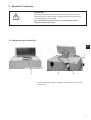
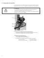
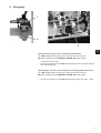
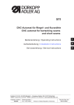
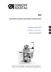
506-3
Instructions, complete
Operating Instructions
1
Installation Instructions
2
Service Instructions
3
Postfach 17 03 51, D-33703 Bielefeld • Potsdamer Straße 190, D-33719 Bielefeld
Telefon +49 (0) 521 / 9 25-00 • Telefax +49 (0) 521 / 9 25 24 35 • www.duerkopp-adler.com
Ausgabe / Edition:
10/2008
Änderungsindex
Rev. index: 01.0
Printed in Federal Republic of Germany
Teile-Nr./Part.-No.:
0791 506011
Instructions, complete
506-3
Overview
Operating table
Operating Instructions
Installation Instructions
Service Instructions
Pneumatic circuit plan
9770 506002
Interconnection-diagram
9890 506003 B
All rights reserved.
Property of Dürkopp Adler AG and copyrighted. Reproduction or publication of the content in any manner,
even in extracts, without prior written permission of Dürkopp Adler AG, is prohibited.
Copyright © Dürkopp Adler AG - 2008
Foreword
This instruction manual is intended to help the user to become familiar
with the machine and take advantage of its application possibilities in
accordance with the recommendations.
The instruction manual contains important information on how to
operate the machine securely, properly and economically. Observation
of the instructions eliminates danger, reduces costs for repair and
down-times, and increases the reliability and life of the machine.
The instruction manual is intended to complement existing national
accident prevention and environment protection regulations.
The instruction manual must always be available at the machine/sewing
unit.
The instruction manual must be read and applied by any person that is
authorized to work on the machine/sewing unit. This means:
–
–
–
Operation, including equipping, troubleshooting during the work
cycle, removing of fabric waste,
Service (maintenance, inspection, repair) and/or
Transport.
The user also has to assure that only authorized personnel work on the
machine.
The user is obliged to check the machine at least once per shift for
apparent damages and to immediatly report any changes (including the
performance in service), which impair the safety.
The user company must ensure that the machine is only operated in
perfect working order.
Never remove or disable any safety devices.
If safety devices need to be removed for equipping, repairing or
maintaining, the safety devices must be remounted directly after
completion of the maintenance and repair work.
Unauthorized modification of the machine rules out liability of the
manufacturer for damage resulting from this.
Observe all safety and danger recommendations on the machine/unit!
The yellow-and-black striped surfaces designate permanend danger
areas, eg danger of squashing, cutting, shearing or collision.
Besides the recommendations in this instruction manual also observe
the general safety and accident prevention regulations!
General safety instructions
The non-observance of the following safety instructions can cause
bodily injuries or damages to the machine.
1. The machine must only be commissioned in full knowledge of the
instruction book and operated by persons with appropriate training.
2. Before putting into service also read the safety rules and
instructions of the motor supplier.
3. The machine must be used only for the purpose intended. Use of
the machine without the safety devices is not permitted. Observe all
the relevant safety regulations.
4. When gauge parts are exchanged (e.g. needle, presser foot, needle
plate, feed dog and bobbin) when threading, when the workplace is
left, and during service work, the machine must be disconnected
from the mains by switching off the master switch or disconnecting
the mains plug.
5. Daily servicing work must be carried out only by appropriately
trained persons.
6. Repairs, conversion and special maintenance work must only be
carried out by technicians or persons with appropriate training.
7. For service or repair work on pneumatic systems, disconnect the
machine from the compressed air supply system (max. 7-10 bar).
Before disconnecting, reduce the pressure of the maintenance unit.
Exceptions to this are only adjustments and functions checks made
by appropriately trained technicians.
8. Work on the electrical equipment must be carried out only by
electricians or appropriately trained persons.
9. Work on parts and systems under electric current is not permitted,
except as specified in regulations DIN VDE 0105.
10. Conversion or changes to the machine must be authorized by us
and made only in adherence to all safety regulations.
11. For repairs, only replacement parts approved by us must be used.
12. Commissioning of the sewing head is prohibited until such time as
the entire sewing unit is found to comply with EC directives.
13. The line cord should be equipped with a country-specific mains
plug. This work must be carried out by appropriately trained
technicians (see paragraph 8).
It is absolutely necessary to respect the safety
instructions marked by these signs.
Danger of bodily injuries !
Please note also the general safety instructions.
Contents
Page:
Part 2: Installation Instructions Cl. 506-3
1.
Scope of Delivery . . . . . . . . . . . . . . . . . . . . . . . . . . . . . . . . . . . . . . . . . . . . . .
3
2.
2.1
2.2
2.3
Installation of the Unit
Transport . . . . . . . . . . . . . . . . . . . . . . . . . . . . . . . . . . . . . . . . . . . . . . . . . . . .
Setting the Work Height . . . . . . . . . . . . . . . . . . . . . . . . . . . . . . . . . . . . . . . . . . .
Attaching the Yarn Stand . . . . . . . . . . . . . . . . . . . . . . . . . . . . . . . . . . . . . . . . . .
3
3
4
3.
3.1
Electrical Connection
Connecting the Control Unit . . . . . . . . . . . . . . . . . . . . . . . . . . . . . . . . . . . . . . . .
5
4.
Pneumatic Connection . . . . . . . . . . . . . . . . . . . . . . . . . . . . . . . . . . . . . . . . . . .
6
5.
Oil supply . . . . . . . . . . . . . . . . . . . . . . . . . . . . . . . . . . . . . . . . . . . . . . . . . . .
7
2
1. Scope of Delivery
–
–
–
–
–
–
–
–
Frame with sewing drive and table 1100 x 736 mm
Sewing machine with integrated bobbin winder
Quick control unit
Compressed air maintenance unit
Yarn stand
Foot switches
Sewing light
Tools and small parts in the accessories pack
2. Installation of the Unit
ATTENTION !
The unit may only be set up by trained personnel.
Before installing the unit it is essential that all transport fastenings be
removed!
2
2.1 Transport
For in-house transport lift the unit and transport on a suitable wagon
(e.g. lift truck).
2.2 Setting the Work Height
The work height can be set between 76 cm and 106 cm (measured to
the upper edge of the table).
The unit is set at a work height of 82 cm at the factory.
Caution: danger of injury
The automatic sewing machine is very heavy. Once the screws have
been removed the table top may fall at high speed.
When adjusting the working height it is essential to use auxiliary
equipment such as trestles, lifting tackle and the like.
3
1
–
–
Loosen the locking screws 1 on both sides of the frame.
Set the base plate horizontally at the desired work height.
In order to avoid a tilt pull out or push in the base plate uniformly on
both sides.
Tighten the locking screws 1.
–
2.3 Attaching the Yarn Stand
2
2
–
4
Insert the yarn stand 2 into the appropriate hole in the table and
attach with the nuts and washers.
3. Electrical Connection
ATTENTION !
All work on the electrical components of the sewing unit may be
carried out only by electricians or appropriately trained personnel.
The mains plug must be pulled.
The instruction manual of the drive’s manufacturer must
imperatively be respected!
3.1 Connecting the Control Unit
2
1
3
–
2
Screw the operating panel 1 together with its bracket 2 onto the
control unit 3.
5
4. Pneumatic Connection
For the operation of the clamp lifting, thread tension opening, needle
cooling, etc. the unit must be supplied with water-free compressed air.
ATTENTION !
For a flawless functioning of the pneumatic control processes the
compressed air supply must be laid out as follows:
Even at the instant of greatest air consumption the minimum operating
pressure may not fall below 5 bar.
1
2
3
Connecting the compressed air maintenance unit
– Connect the connection hose 3 for the maintenance unit to the
compressed air supply with the enclosed coupling.
Setting the operating pressure
– The operating pressure is 6 bar.
It can be seen on the pressure gauge 2.
– For setting the operating pressure pull knob 1 up and turn.
Turning clockwise
= Increase pressure
Turning counterclockwise
= Decrease pressure
6
5. Oil supply
1
2
3
2
Filling the oil reservoir for shuttle-track lubrication
Only DA-10 lubricating oil may be used to fill the oil reservoir.
DA-10 is available from DÜRKOPP ADLER AG retail outlets.
– Unscrew oil-filler cap 1.
– Fill the oil reservoir 2 with DA-10 lubricating oil to the upper edge of
the embossed text.
Checking the oil lever in the central recirculating-lubrication unit
Only DA-10 lubricating oil may be used to fill the oil reservoir.
DA-10 is available from DÜRKOPP ADLER AG retail outlets.
–
Fill the oil reservoir 3 with DA-10 lubricating oil to the “max.” mark.
7
Notes:
8