1
Pro-Watch Software Suite
Architect and Engineering
Specifications
Revision 3.7.0
Ed. July 16, 2008
Contents
1
General................................................................................................. 5
1.1
2
Summary ................................................................................................................... 5
1.1.1
References..................................................................................................... 5
1.1.2
System Overview.......................................................................................... 6
Products ............................................................................................ .. 7
2.1
System Software Requirements ............................................................................... 7
2.1.1
Multi-User/Network Capabilities ................................................................. 7
2.1.2
Concurrent Licensing.................................................................................... 7
2.1.3
Microsoft Certifications................................................................................ 8
2.1.4
Security Key ............................................................................................... 10
2.1.5
Access Control Software Suite ................................................................... 10
2.1.6
Terminal Services ....................................................................................... 14
2.1.7
Operating System........................................................................................ 14
2.1.8
Relational Database Management System.................................................. 15
2.1.9
LDAP/ Microsoft Active Directory Services.............................................. 15
2.1.10 OLE-DB ..................................................................................................... 16
2.1.11 Unicode ...................................................................................................... 16
2.1.12 Encryption .................................................................................................. 16
.
1
Ed. July 16, 2008
2.1.13 Compliance and Validation........................................................................ 16
2.1.14 Clean Room Solution …………………………………………………….17
2.2
2.3
2.4
Operational Requirements....................................................................................... 18
2.2.1
System Operations ...................................................................................... 18
2.2.2
Access Control Functional Requirements................................................... 28
2.2.3
System Administration ............................................................................... 52
2.2.4
Application Localization............................................................................. 57
2.2.5
Event Manager............................................................................................ 57
Hardware Requirements.......................................................................................... 59
2.3.1
Hardware Support....................................................................................... 59
2.3.2
Server/Workstation Hardware Configuration ............................................. 59
Field Controllers ..................................................................................................... 61
2.4.1
System Controllers...................................................................................... 61
2.4.2
Cardkey Controllers:................................................................................... 90
2.5
Enclosure................................................................................................................. 92
2.6
Electrical Power Requirements ............................................................................... 92
2.7
Environmental Conditions ...................................................................................... 92
2.8
System Interfaces .................................................................................................... 94
2.8.1
Analog CCTV Switchers ............................................................................ 94
2.8.2
Digital Video Recording............................................................................. 96
.
2
Ed. July 16, 2008
3
4
2.8.3
E-Mail ....................................................................................................... 159
2.8.4
Stentonfon Intercom Interface .................................................................. 159
2.8.5
VISTA-128FBP and VISTA-250FBP controllers ............................. 160
2.8.6
Visitor Management System (VMS)……………………………………165
Execution ......................................................................................... 171
3.1
Examination .......................................................................................................... 171
3.2
Installation............................................................................................................. 171
3.3
Testing and Certification....................................................................................... 171
CPU Minimum Requirements ....................................................... 172
4.1
Pro-Watch Lite Edition ......................................................................................... 172
4.2
Pro-Watch Professional Edition............................................................................ 177
4.3
Pro-Watch Corporate Edition................................................................................ 177
4.4
Pro-Watch Enterprise Edition……………………………………………………182
4.5
HVMS……………………………………………………………………………184
.
3
Ed. July 16, 2008
.
4
Ed. July 16, 2008
1 General
1.1 Summary
The intent of this document is to specify the minimum criteria for the design, supply,
installation, and activation of the Security Management System, hereinafter referred to as the
System, which shall be a modular and network enabled access control system. The System shall
be capable of handling large proprietary corporations with multiple remote sites, alarm
monitoring, video imaging and badging, paging, digital video control and CCTV switching that
allows for easy expansion or modification of inputs and remote control stations.
1.1.1
1.1.1.1
•
•
1.1.1.2
•
•
1.1.1.3
•
1.1.1.4
•
•
References
Federal Communications Commission (FCC):
FCC Part 15 – Radio Frequency Devices
FCC Part 68 – Connection of Terminal Equipment to the Telephone Network
Underwriters Laboratories (UL):
UL294 – Access Control System Units
UL1076 – Proprietary Burglar Alarm Units and Systems
National Fire Protection Association (NFPA):
NFPA70 – National Electrical Code
Electronic Industries Alliance (EIA):
RS232C – Interface between Data Terminal Equipment and Data Communications
Equipment Employing Serial Binary Data Interchange
RS485 – Electrical Characteristics of Generators and Receivers for use in Balanced
Digital Multi-Point Systems
.
5
Ed. July 16, 2008
1.1.1.5. Federal Information Processing Standard (FIPS):
•
•
1.1.2
Advanced Encryption Standard (AES) (FIPS 197)
FIPS 201: Personal Identity Verification (PIV) of Federal Employees and Contractors
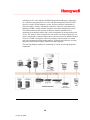
System Overview
The Security Management System shall integrate access control, alarm monitoring, CCTV,
digital video, video badging, and database management. A modular and network enabled
architecture shall allow maximum versatility for tailoring secure and dependable access and
alarm monitoring solutions for medium and large facilities. The System shall at a minimum
include the following capabilities:
•
•
•
•
•
•
•
•
•
Direct wire operation, local area network (LAN) (Ethernet) or wide area network
(WAN) operation, or remote operation via modem. When configured for dialup, any
one port can support multi dialup locations.
A flexible and modular design shall provide ease of installation, robustness, reliability,
and expansion.
Distributed architecture shall allow controllers to operate independently of the host.
The architecture shall place key access decisions, event/action processing, and alarm
monitoring functions within the controllers, eliminating degraded mode operation.
Communication between the server/workstations, controllers, and other hardware shall
be via the Security Management System software.
Proprietary software programs and control logic information used to coordinate and
drive system hardware shall be stored in read-only memory (PROM).
Upgrades to the hardware and software shall occur seamlessly without the loss of
database, configurations, or historical report data.
Flash memory shall support firmware updates and revisions to be downloaded to the
system via modem or system communication.
Both supervised and non-supervised alarm point monitoring shall be provided. Upon
recognition of an alarm, the system shall be capable of switching CCTV cameras that
are associated with the alarm point.
Manual or automatic arming or disarming alarm points shall be performed by time of
day and day of week.
.
6
Ed. July 16, 2008
•
Database partitioning shall provide the option to restrict access to sensitive information
by user ID.
2 Products
2.1 System Software Requirements
The system shall be a modular and network enabled access control system. The System shall be
capable of controlling multiple remote sites, alarm monitoring, video imaging, video badging,
paging, digital video and CCTV switching and control that allows for easy expansion or
modification of inputs and remote control stations. The System control at a central computer
location shall be under the control of a single software program and shall provide full
integration of all components. It shall be alterable at any time depending upon facility
requirements. System reconfiguration shall be accomplished online through system
programming. The System shall include the following:
2.1.1
Multi-User/Network Capabilities
The System shall support multiple operator workstations via local area network/wide area
network (LAN/WAN). The communications between the workstations and the server computer
shall utilize the TCP/IP standard over industry standard IEEE 802.3 (Ethernet). The
communications between the server and workstations shall be supervised, and shall
automatically generate alarm messages when the server is unable to communicate with a
workstation. The operators on the network server shall have the capability to log on to
workstations and remotely configure devices for the workstation. Standard operator permission
levels shall be enforced, with full operator audit.
2.1.2
Concurrent Licensing
The System shall support concurrent client workstation licensing. The System application shall
be installed on any number of client workstations, and shall provide the ability for any of the
client workstations to connect to the database server as long as the maximum number of
concurrent connections purchased has not been exceeded.
.
7
Ed. July 16, 2008
2.1.3
•
•
Microsoft® Certifications
A Microsoft® Gold Certified Partner shall develop the System software. Microsoft
Gold Certified Partners meet a higher set of criteria for each category, including
enhanced certification and a portfolio of real-world customer references, and are thus
identified as the most skilled partners in specific solution areas. Microsoft Gold
Certified Partners encompass a broad range of technical expertise, including
specialized disciplines such as e-commerce, networking, collaboration, commitment to
emerging technology and providing excellence in customer solutions.
The System shall be certified for both Windows 2000 Server as well as Windows 2000
Professional. Systems that are not certified for BOTH operating systems shall be
unacceptable.
2.1.3.1
Microsoft Windows 2000 Certification Common Requirements:
The System shall:
• Perform primary functionality and maintain stability
• Provide 32-bit components and document any 16-bit code
• Support Long File Names and UNC paths
• Support printers with long names and UNC paths
• Not read from or write to WIN.INI, SYSTEM.INI, AUTOEXEC.BAT or
CONFIG.SYS
• Ensure non-hidden files outside of your application directory have associated file
types, and all file types have associated icons, descriptions and actions
• Perform Windows version checking correctly
• Hardware drivers must pass WHQL testing
• Install using a Windows installer-based package that passes validation testing
• Install to Program Files by default
• Support Add/Remove Programs properly
• Ensure correct uninstall support
• Not attempt to replace files that are protected by Windows File Protection
• Support standard system size, color, font and input settings
.
8
Ed. July 16, 2008
•
•
•
•
Ensure compatibility with the High Contrast option
Provide documented keyboard access to all features
Expose the location of the keyboard focus
Not place shortcuts to documents, help or uninstall in the Start Menu
Microsoft Windows 2000 Professional Unique Certification
requirements:
2.1.3.2
In addition to the common requirements, the System shall:
•
•
•
•
•
•
•
•
Support AutoPlay of compact disks
Observe rules in componentization
Identify shared components
Component producers: Build side-by-side components
Application developers: Consume and install side-by-side components
Install any non side-by-side shared files to the correct locations
Classify and store application data correctly
Degrade gracefully on access denied:
o Run in a secure Windows environment
o Adhere to system-level Group Policy settings
o Applications that create ADM files shall properly store their ADM file
settings in the registry
o Not rely exclusively on sound
o Support multiple monitors
2.1.3.3
Microsoft Windows 2000 Server Unique Certification requirements:
In addition to the common requirements, the System shall:
•
•
•
•
•
Not overwrite non-proprietary files with older versions
Install shared files to the correct locations
Recount all shared application files during installation
Decrement the count on shared application files during uninstall
Document services that require more than User level privileges to run
.
9
Ed. July 16, 2008
• Win32 clients running in the context of a trusted domain account must support Single
Sign-On.
2.1.4
Security Key
The System shall only require a single security key dongle to be present on the database server
for the System to operate. Security keys shall not be required at the client workstations. The
System shall allow a user to read the information that is programmed on the server security key
dongle. The System shall support export of the information using the ‘Export Dongle
information’ button, which shall allow the user to forward to the integrator when upgrading
new dongle features.
2.1.5
Access Control Software Suite
The System shall offer a premier security management software suite available in three scalable
versions: Lite, Professional, Corporate, and Enterprise Editions. The System platform shall
offer a complete access control solution; alarm monitoring, video imaging, badging and CCTV
control. All four editions of software shall provide a convenient growth path from small to
midsized applications to global enterprise solutions.
2.1.5.1
Lite Edition
Pro-Watch® Lite Edition shall provide a security management solution for entry level
applications. The System shall be designed to maximize value and decrease installation time
including enhanced ease-of-use features Built-in software wizards shall enhance system
uniformity across sites, reduce installation time, and improve the overall learning curve for new
users. The System shall utilize the Microsoft Data Engine (MSDE) to provide a powerful
solution for applications with one to four users and up to 32 entrances. Pro-Watch Lite sites
shall be easily upgraded to Professional, Corporate or Enterprise Edition. The Lite platform
shall include the following features and benefits:
•
Ease-of-use features accelerate system setup, configuration and deployment.
•
Powerful integration to Honeywell’s Rapid Eye™ platform and built-in video MUX.
•
Seamless growth from a two-door system to a 20,000-door Enterprise system without
ever having to change user interfaces or learn a new application.
•
Seamless integration with other third party facility management subsystems including
video, pagers, intercoms, biometric devices, and digital storage devices. Pro-Watch
.
10
Ed. July 16, 2008
supports a “generic channel” capability that allows customized interfaces to previously
unsupported third-party devices.
•
Integrated badge, hardware and permission wizards reduce the number of clicks
required to configure and deploy a system.
•
Hand geometry template storage and administration through application.
•
Multiple database partitioning provides a higher level of security by allowing the
system administrator to restrict access to sensitive information by user ID.
•
Direct import of select versions of AutoCAD drawings with layer views reducing
commissioning costs and time.
•
Global search utility allows information to be easily accessed and recalled.
•
Integrated badging and video functions with a single user interface eliminate the need
for multiple software/hardware packages and redundant data entry.
•
Search templates are available for quick lookup of all system parameters.
•
Macros combine multiple operations into a single keystroke or mouse click.
•
Integrated real-point status monitor allows for quick evaluation of point status.
•
128-bit data encryption between host and PW-5000/6000 access control panels.
•
The System shall support 1 to 4 users and up to 32 doors.
•
The System shall use Microsoft SQL-based Data Engine (MSDE 2000 or later).
•
The System shall operate on Windows XP Professional Edition Operating System.
2.1.5.2
Professional Edition
Professional Edition shall provide an economical solution for small to midsized applications.
Professional Edition shall operate efficiently without the requirement of a server-based
operating system. The System shall utilize Microsoft Data Engine (MSDE 2000 or later) for
smaller applications from 1 to 5 users and up to 64 doors.
The System shall provide a complete set of MSDE database tools designed to easily backup,
restore, and maintain the System database. The System shall allow for expansion to Corporate
and/or Enterprise Edition without changing the user interface or database structure. The
common platform shall include the following features and benefits:
.
11
Ed. July 16, 2008
•
•
•
•
•
•
•
•
•
•
•
•
•
•
•
•
•
Certified for Microsoft Windows 2000 Professional and Server
Leverages existing network infrastructure by using standard network protocols to
communicate to all system hardware
CHIP hardware protocol support (communicates to existing Honeywell’s Star II series
controllers)
PW series hardware protocol support (communicates to existing Honeywell’s PW2000, PW-3000, and PW-6000 series controllers)
SEEP hardware protocol support (communicates to existing Honeywell’s Star I, 4100,
and 800 series controllers)
Comprehensive database-partitioning scheme shall allow extensive flexibility in
managing operator permissions
Real-time status monitor shall provide “at a glance” status of the entire System and the
ability to quickly evaluate the details of any point in the System
Report Manager shall provide savable report templates, exporting options, and a
scheduler for added user convenience
Integrated digital video solutions from Honeywell including Rapid Eye series, Fusion
series recorders, as well as IP-based solutions from the Honeywell Video Management
System (HVMS) series
Database Import/Export utility shall allow information to be transferred dynamically to
and from third party databases, enabling a convenient interface to HR or Active
Directory controlled systems
Integrated Precise Biometric Smart Card enrollment allows for fingerprint capture and
programming shall be done within the System application
Direct import of AutoCAD drawings with layer views
Integrated badging and CCTV functions in a single user interface shall eliminate the
need for multiple software systems and reduces data entry time
The System shall provide support for hardware protocols from a variety of
manufacturers
The System shall support up to 5 users and 64 doors
The System shall use SQL-based Microsoft Data Engine (MSDE 2000 or later)
The System shall operate on Windows 2000, Vista, and XP Professional as well as
Windows 2000 or 2003 Server
.
12
Ed. July 16, 2008
2.1.5.3
Corporate Edition
Corporate Edition shall be provided for more demanding security management applications.
The System shall operate in the Windows 2000 server environment and utilize SQL 2005 as the
database engine.
In addition to the features listed for the Professional Edition, Corporate Edition shall also
include the following features and benefits:
•
•
•
•
•
2.1.5.4
Flexible software licensing packages and hardware components shall allow the System
to be tailored to individual application needs.
E-mail capability to assign an e-mail address that the System shall notify should the
alarm originate from the designated point. This process shall be a function of SQL
2005 Server, which shall negotiate e-mail transfer to the Microsoft Exchange Server.
The System shall support 2 users and 96 readers as a standard, and will be upgradeable
to unlimited users and readers
The System shall utilize Microsoft SQL Server 2005 Standard Edition Data Engine
The System shall utilize Windows 2000 or 2003 Server as primary operating system
Enterprise Edition
Enterprise Edition shall incorporate regional server architecture to meet the needs of global
business. Regional sites shall operate autonomously with all information required to maintain
security locally.
The enterprise server shall maintain any critical system information via synchronization with
each regional site. This system of synchronization shall ensure the integrity of data throughout
the enterprise.
The regional server architecture shall provide an unparalleled degree of reliability and
flexibility through the use of multiple regional Windows PCs sharing a common master
cardholder and photo ID badging database.
One Enterprise Server shall provide global management of all regional servers and shall act as a
central collecting point for all hardware configurations, cardholder and clearance code data and
transaction history. The Enterprise Edition includes the following features and benefits:
•
Shall provide the ability to activate or deactivate a card from anywhere in the
Enterprise, while having the card’s status updated at all of the regions and the
associated controllers.
.
13
Ed. July 16, 2008
•
•
•
•
•
•
•
•
•
2.1.6
Existing Corporate Edition system shall be easily integrated into an Enterprise Edition
without loss of data or history.
The System shall provide one central cardholder and badging file so that an operator in
any region in an Enterprise shall have the capability to view and modify cardholder
data and grant or deny access enterprise-wide.
A single uniform application program shall be used to install and configure the
Enterprise server, regional server, and all client workstations
The System shall provide the ability to service alarms and report on their status from
any region, covering the entire Enterprise.
The System shall provide database reporting capability on the central cardholder
database.
The System shall support unlimited users and readers.
The System shall utilize Microsoft SQL Server 2005 Standard Edition Data Engine.
The System shall utilize Windows 2000 or 2003 Server as primary operating system.
The System shall incorporate regional server architecture to meet the needs of global
business.
Terminal Services
The System shall support Windows 2000 Terminal Services. Terminal Services shall allow the
System server application to reside on the Windows Terminal Server while client access shall
be obtained via a standard Web browser interface. Operating systems supporting a standard
Web browser shall be capable of utilizing the thin client architecture. The System shall support
unlimited connections, based on concurrent licensing, to the System software. Full functionality
shall be obtained through the intranet connection allowing full administration and monitoring
without the need for a local installation. This functionality also allows video badging and image
capture to occur remotely without the need to install the application locally.
2.1.7
Operating System
The System shall support Windows 2000 Server and Windows 2003 Server for the Corporate
and Enterprise Editions as well as Windows 2000 Professional Edition and Windows XP
Professional Edition as the host operating system for the Professional Edition product. It shall
also support Windows 2000, Vista, and XP Professional as a client operating system for all
three versions of software in the Pro-Watch software suite.
.
14
Ed. July 16, 2008
2.1.8
Relational Database Management System
The System shall support industry standard relational database management systems. This shall
include relational database management system Microsoft SQL Server 2005.
2.1.9
LDAP/ Microsoft Active Directory Services
The System shall provide support of Lightweight Directory Access Protocol (LDAP) for
enabling the user to locate organizations, individuals, and other resources such as files and
devices in a network, whether on the public internet or on a corporate intranet. The System
shall provide a direct link to Microsoft Active Directory Services. This integration shall allow
for a centralized data repository that can be utilized by systems throughout a corporate
enterprise. The System shall allow the transfer of Active Directory users via the Data Transfer
Utility. Active Directory users may be imported into the System database. Conversely, System
users shall be capable of being exported to the Active Directory.
.
15
Ed. July 16, 2008
2.1.10 OLE-DB
The System shall utilize Microsoft’s OLE-DB object-oriented, database access method.
Microsoft’s OLE-DB method shall provide support of not only relational databases, but also to
“hierarchical data sets” such as Microsoft Exchange stores and XML record sets. OLE-DB
shall allow easier integration of disparate data sources.
2.1.11 Unicode
The System shall utilize Unicode worldwide character set standard. Unicode shall enable a
single software product to be targeted across multiple platforms, languages and countries. The
System shall support double-byte character sets to facilitate adaptation of the System user
interface and documentation to new international markets. This enhanced flexibility shall allow
the System to expand its multilingual portfolio, which includes at a minimum English, French,
and German.
2.1.12 Encryption
The System shall provide true 128-bit data encryption between the host and PW-6000
intelligent controllers. The encryption shall ensure data integrity that is compliant with the
requirements of FIPS and SCIF environments. Master keys shall be downloaded to the
intelligent controller, which shall then be authenticated through the System based on a
successful match.
2.1.13
Compliance and Validation
The System shall incorporate signature authentication where modifications to System resources
will require either a single or dual signature authentication. Administrators will have the ability
to select specified devices in the System where data manipulation will be audited and
signatures will be required to account for the data modification. Upon resource modification,
the user will be required to enter a reason for change or select from a list a predefined reason.
All data will be securely stored and maintained in the database and can be viewed using the
reporting tool. This functionality will meet the general requirements of Validation and
Compliance through Digital Signatures with special attention to the case of CFR 11 Part B
compliance.
.
16
Ed. July 16, 2008
2.1.14
Clean Room Solution
2.1.14.1 Overview
The System shall provide a clean room solution which enables users to manage their “Clean
Environments” or other areas requiring special restricted access through a process oriented
graphical user interface.
The clean room solution shall provide tools that enable security directors and technical review
boards to audit and implement complex human work flows in ultra clean environments or other
areas. The System shall enforce contamination level-based access control based on a numerical
value system. Contamination levels can be adjusted dynamically to parallel the evolution of
complex chemical or biological processes by the staff. The clean room solution shall enable the
user to assign a contamination level (number from 1 to 100) to each room. Numbers shall
ascend in the order of un-cleanliness; that is, 1 is the cleanest room and 100 is the least clean
room, and a cardholder can only travel from “clean” to “less clean.” Access shall be granted
from a lower contamination room to a higher contamination room, but shall be denied from a
higher contamination room to a lower contamination room.
For example, a valid cardholder shall enter the common lobby, which is not configured as a
clean room. If the cardholder enters Laboratory 1 with a contamination level of 10 (least
contaminated), he may subsequently be granted access to Laboratory 2 (contamination level of
20) or Laboratory 3 (contamination level of 30) because his path ascends in contamination level
from least to most contaminated. Therefore, if the user first enters Laboratory 3, he shall not
thereafter be granted access to Laboratories 2 and 1 until the contamination levels are reset.
2.1.14.2 Configuration
The user shall have the capability of adding, editing, or deleting clean rooms. The System shall
provide a Description field allowing the user to enter the Logical Device name that corresponds
to the clean room’s door or reader. The user shall have the capability to select a default time
zone for the room from the Default time zone drop-down list. This time zone shall define the
hours during which access is possible. The user shall select a reader for the room door utilizing
the Logical Device field icon to display the list of available readers. The System shall also
provide the capability to assign an alternate Time Zone to assign to a secondary reader when
the door is configured with two readers, (one entry and one exit reader). The user shall select a
Time Zone from the dropdown list next to the Alternate Time Zone field. Access to clean
.
17
Ed. July 16, 2008
rooms shall be defined through cardholder Clearance Codes. The System shall provide a
“Cards” tab which shall display the Access Allowed column. This column shall indicate which
valid cardholders currently have access to the clean room selected at the top of the screen.
The System shall provide two methods to manage the Access Allowed column (select or deselect the checkboxes):
• Manual—The user shall have the capability to click the checkbox to select and de-select.
Additionally, the toolbar at the top of the Clean Room Configuration screen shall allow the user
to reset all cards or reset card (resets the selected cardholder). This method shall be used when
selecting or deselecting only some of the cards.
• Event procedure—The user shall have the capability to create a trigger and procedure that will
run automatically according to a set schedule. This method shall reset every valid card for the
clean room to give all valid cardholders access. The Time checkbox shall set the time of day at
which the stored procedure will reset all clean rooms.
2.2 Operational Requirements
2.2.1
2.2.1.1
System Operations
Password
The System shall use an integrated authentication method which utilizes Windows user
accounts and policies. Client stations will function under the Microsoft recommended default
user rights. Passwords must support scheduled expiration and be capable of prompting the user
for a password change automatically as a part of the Windows login process. Additionally,
passwords will support complexity rules such as length of password and required number of
alphanumeric characters as established by the Windows policies regarding user accounts.
2.2.1.2
Information Access
The System shall be capable of limiting operator access to sensitive information. Operators
shall have proper authorization to edit the information.
2.2.1.3
Shadow Login
The System shall allow users to login over a currently logged-on user without having the
current user log off the System or Windows 2000. For example, the System shall allow an
.
18
Ed. July 16, 2008
administrator to login over a restricted class user to perform a function on the System that the
current user does not have permission to perform. This provides a level of security in that the
user’s workstation shall never need to go offline or be unattended.
2.2.1.4
User Friendly Graphical User Interface
The System shall be fully compliant with Microsoft graphical user interface (GUI) standards,
with the look and feel of the software being that of a standard Windows application, including
hardware tree based system configuration.
The System shall provide user definable “drag and drop” hardware templates in order to
simplify system setup and maintenance. The user interface shall be designed such that the
ability to add resources such as time zones, clearance codes, alarm types, etc. shall be available
within the functions in which they are used rather that requiring the user to close the function
and navigate to another section of the application to add the resource.
The System shall provide a dependency search to allow the user to determine all the
dependencies of hardware devices in the configuration trees. The search function shall display
the list of assignments at the logical device level to assist the user to select all appropriate
devices when removing an object from the configuration.
The System shall support of graphical user manager utilities (wizards) to ease the enrollment
process for users, controllers, communication channels, badgeholders, and logical devices. The
wizards will be made available through a Welcome screen at main application entry as well as
at the individual resource creation point.
2.2.1.5
Help
The main System user interface shall include a help icon which shall require only one click to
activate. The standard special function key “F1” shall have the capability to be programmed to
provide access to the help system.
2.2.1.6
•
•
Guard Tour
The System shall include a guard tour module, which shall allow the user to program
guard tours for their facility. The tours shall not require the need for independent or
dedicated readers.
The System shall provide the ability to use the same logical device more than once in a
guard tour. The logical device shall be selected from a resource box located on the left
.
19
Ed. July 16, 2008
•
•
•
•
•
2.2.1.7
•
•
2.2.1.8
•
side of the screen. Selecting this box shall bring all system readers to view for tour
selection.
Once a logical device has been selected, a dialog requesting the ‘Time’ required
reaching designation shall appear. This entry shall be in military format (00:00) and
represents the amount of time required to reach each checkpoint.
After the ‘Time’ has been entered, the tolerance needs to be entered, the ‘+’ and ‘-’
values shall be defined. A text box shall allow the user to enter the time tolerated for
early and late arrivals.
The user shall be able to ‘Start Guard Tour’ in the Guard Tour screen and bring up a
‘Select Guard’ dialog box. Selecting a Guard from this list shall assign that user
(guard) to that tour. The listing of guards that appear in the dialog box shall be pulled
from the cardholder screen. The cardholder screen includes a ‘Guard’ checkbox.
Selecting this box shall register the badgeholder/cardholder as a ‘Guard’ with the
capability to run tours.
If the times defined in the tour are not met within the time allotted, an alarm shall be
sent to the monitor.
The user shall have the capability to run multiple tours simultaneously.
Secure Mode Verification
The System shall provide ‘Secure Mode’ control from the verification viewer. This
shall allow a user or guard to decide the access of an individual who presents his/her
card at a designated secure mode reader. Readers shall be flagged as secure mode
readers from the logical device. Reader definition shall include a check box for Secure
Mode time zone definition. Standard access rules shall apply to any reader designated
as secure mode until the verification window has been opened and the specified reader
has been selected. In the event that a secure mode reader is enabled, the System shall
display the cardholder’s stored image, as well as any binary large object (BLOB)
associated with the user, including but not limited to, signature, documents, secondary
photo, and the user shall have the capability to either grant or deny access to the logical
device via ‘Accept’ or ‘Deny’ buttons on the viewer box.
The System shall provide the ability to print the log from the verification window.
Database Partitioning
The System shall support dynamic partitioning. Systems in which partitions are set up
at installation and cannot be easily changed shall be unacceptable. The System shall
.
20
Ed. July 16, 2008
•
support the addition and deletion of items to the partitioning scheme as required. The
System shall be capable of limiting an operator’s access to one, or multiple partitions.
Information which can be separated into partitions shall include: Alarm Pages, Areas,
Badge Profiles, Badge Ranges, Badge Statuses, Badge Types, BLOB Types, Brass
Keys, Card Formats, Users, User Classes, Clearance Codes, Companies, Dial Up
Schedules, Event Types, Event Triggers, Event Procedures, Groups, Holidays,
Keyboard Accelerators, Maps, Modem Pools, Alarm Pathways, Routing Groups, Status
Groups, Time Zones, Workstations, Device Types, Hardware Classes, Hardware
Templates, Logical Devices, Panels, Channels, Sites, CCTV Camera Views, CCTV
Monitor Views, Reports, and Badge Records.
Each item shall be capable of being assigned, or being available to, multiple partitions.
Partitioned items shall not be visible to operators that have not been assigned access to
at least one of those same partitions. The System shall allow partitioning to be turned
on or off for each table as required. Systems that do not support assigning of individual
items to multiple partitions shall be unacceptable.
.
21
Ed. July 16, 2008
2.2.1.9
Status Groups
The System shall support a real-time system status monitor that graphically depicts all logical
devices. The Status Groups window shall be a split window with logical device icons displayed
in the upper portion and the Device Types associated with a selected logical device displayed in
the lower portion. The Status Groups shall be available in the hardware configuration view and
the alarm monitor view.
2.2.1.9.1
Upper view
The icons representing each logical device within this view shall change based upon the status
of that logical device. Different icons shall be available to indicate:
•
•
•
•
•
•
•
•
•
2.2.1.9.2
•
Normal State
Indeterminate State
Reader Off-Normal State
Input Off-Normal State
Output Off-Normal State
Reader and Input Off-Normal State
Reader and Output Off-Normal State
Input and Output Off-Normal State
Total Alarm State
Lower view
Individual device types (readers, inputs, outputs which are further defined as door
position switches, request-to-exit devices, enunciators, etc.), which make up the
selected logical device, shall be displayed in the lower view. This lower view shall
include an icon for each device type and indicate the category (input point, output
point, reader) and the status of the individual device types that make up the logical
device (normal, energized, locked, unlocked, in-alarm). Note that when a reader device
type is not in an off-normal status, the reader mode is displayed (card-only, PIN-only,
card and PIN, card or PIN).
.
22
Ed. July 16, 2008
2.2.1.9.3
•
Status Group Filter
The Status Groups window shall be filterable to show only logical devices which are
currently in an off-normal condition based on the following:
o Reader Filters
•
•
•
•
•
Unknown
Disabled
Locked/Unlocked
Facility Code
Timed Override
o Input Filters
•
•
•
•
•
•
•
•
•
•
Alarm
Trouble
Held Open
Forced Open
Open Circuit
Short Circuit
Exit Warning
Hardware Masked
Software Masked
Offline
o Output Filters
•
•
•
•
•
Energized
Trouble
Hardware Masked
Software Masked
Offline
.
23
Ed. July 16, 2008
2.2.1.10 Keyboard Accelerators
The System shall allow the user to use a shortcut key to enable designated system commands.
The System operator shall have the capability to set up accelerators for two options: Commands
and Event Procedures.
The operator shall have the capability to add, edit, and delete accelerators for commands and
event procedures, as well as grant or revoke user access to these options. The keyboard
accelerator dialog box shall include a user definable description, the New Shortcut Key
Combination (for example, Ctrl+Shift+T), Checkboxes for Command Procedure and Event
Procedure with drop down lists. The Keyboard Accelerator icon shall be displayed in the right
System pane, for single mouse click execution.
2.2.1.11 Void Card upon Lack of Use
The System shall allow system operators to set a predefined time period in which cardholders
must swipe their card through a card reader in the System. The System shall automatically void
the card if the defined timeframe has elapsed without a card read since the card was created.
2.2.1.12 User Functions and ADA Ability
The System shall provide User Functions and ADA ability that provides the capability to
trigger an event at the System Intelligent Controller when a defined card is presented. The
Extended Strike Time and Extended Held Time for a reader shall be utilized when a card with
ADA checked is presented. Triggers set off by a card read shall include a given user level. This
functionality shall allow only certain users, based on their access privileges, to trigger events at
the door. The user shall have the capability to approach a PIN pad and enter a command digit
followed by up to eight numeric digits. The intelligent controller shall interpret this as a user
function and report that event to the host. A trigger in the System intelligent controller shall fire
based on the PIN entered to perform a panel procedure. The PIN user functions shall exist only
in the trigger definition in the System intelligent controller.
2.2.1.13 Pathways
The System shall support the capability of programming Pathways. A Pathway shall be an
object that combines input points to be masked (shunted) for a set duration, and an output point
to be activated, when a particular card receives a local grant at a reader. For example, a
Pathway shall provide the capability to contain the motion detector inputs along the hallway
path to the user’s office. It shall have the capability to contain the output point for a green light
above the door to the office. When the user presents his valid card to enter the building, the
.
24
Ed. July 16, 2008
input points along the pathway to the office will be masked and the output point activated. If
the user attempts to access any areas other than the Pathway, an alarm will be generated. After
a set number of minutes have elapsed, the input points shall be un-masked and the output point
deactivated. The Pathway shall have the capability to be deactivated before the elapsed time if
another card is configured to “stop” a Pathway in progress. Systems that do not provide
Pathway programming shall be unacceptable.
2.2.1.14 Database Audit Log
The System shall be capable of creating an audit log in the history file following any change
made to the System database by an operator. Each database item shall be selectable to audit the
“add,” “update” or “delete” activities of related to that item. The System shall record:
•
•
•
•
•
•
•
The date and time of the activity
The type of activity (add, update, or delete)
The user who performed the activity
The workstation at which the activity took place
What information was modified
What the old value was
What the new value is
2.2.1.15 Operator Log
The System shall be capable of creating an action log in the history file following actions
performed by an operator. The System shall record:
•
•
•
•
•
•
The date and time of the activity
The user who performed the activity
The workstation at which the activity took place
What activity was performed
What database item on which the activity was performed
What database group to which the item belongs
2.2.1.16 Alarm Routing
The System shall be capable of defining routing groups that determine what event information
shall be routed to a user or class of users. The System shall support routing group rules to be
.
25
Ed. July 16, 2008
assigned to users or user classes, including single or multiple groups. Each item in the routing
group shall be associated with a time zone, which shall control when the routing group is valid.
For example, a specific workstation shall be a valid target for routing after 6:00 pm. Events
from a specific facility (channel) shall be routed to a different set of operators during the day
and certain kinds of events shall be routed to a different set of operators on the weekend. The
System shall support alarm rollover, which shall forward an event to another workstation if it
has not been acknowledged within a specified timeframe. Systems that do not support alarm
rollover shall be unacceptable. Routing of events shall be separated via the following
classifications:
•
•
•
The communication channels on which the event originates
The type of event that is generated
The workstations to which the event should be routed
2.2.1.17 Global and Nested Anti-passback
The System shall support the use of an optional anti-passback mode, in which cardholders are
required to follow a proper in/out sequence within the assigned area. Cards shall be used at a
designated “in” reader then at a designated “out” reader within the area before the card can be
properly used at an “in” reader again. Both hard and soft anti-passback options shall be
available. Hard anti-passback shall not allow a cardholder access when anti-passback rules are
not followed. Soft anti-passback shall allow a cardholder access when anti-passback rules are
not followed but shall create an alarm. In nested anti-passback applications the System shall
prevent user access to an inner area unless the user has properly entered the adjacent outer area.
The System shall support both global and local anti-passback:
•
•
Local: This feature must allow anti-passback areas to be configured within the areas
that are configured on a single intelligent controller.
Global: This feature must allow anti-passback areas to be configured across multiple
intelligent controllers.
2.2.1.18 Two Person Rule
The System shall support a “Two Person Rule” to restrict access to specific access areas unless
two cardholders present two different valid cards to the reader one after the other within a
period time defined by the door unlock time multiplied by a factor of 2. For average doors with
.
26
Ed. July 16, 2008
a door unlock time of 10 seconds, this produces a 20 second window of opportunity. If only one
valid card is presented or if too much time elapses between swipes, the door shall not unlock
and an access denied message shall be generated. The “Two Person Rule” feature shall be
selected for all doors controlling entry to and exit from the specified area.
2.2.1.19 Occupancy Restrictions
The System shall allow the user to define the minimum and maximum occupancy allowed in a
designated area. If the occupancy falls below this minimum amount or the occupancy goes
above this maximum amount, the System shall designate the selected procedure.
2.2.1.20 Hardware Templates
The System shall include the ability to define hardware templates (door templates) in order to
simplify the process of creating an access control system. Hardware templates shall allow a
user to define a “typical” door configuration and then use that template over and over in the
process of defining doors.
Hardware templates shall allow the user to create device types and device property settings
which are specifically designed for the special requirements of each type of access point or
alarm input on each project. The hardware template shall allow the System operator to define a
template for multiple separate doors made up of the same parts. For example, a typical door
may include a card reader, a lock, a door position switch, a request-to-exit device, and a local
sounder for “Door Held Open” alarms. The System operator shall have the capability to create
a template defining the 5 different categories of components that make up the door (device
types), set the default values for each of the components, define any interlocks and/or guard
tour parameters, and then use that template to create the multiple separate doors. By defining
the component types and their default values within the template, the user shall greatly reduce
the overall amount of time necessary to add a door to the System.
An unlimited number of templates shall be supported, allowing a user to pre-define every type
of door configuration within a particular facility. Once the templates have been defined, the
process of building doors shall be quick and simple. All inputs and outputs shall have no predefined or fixed functionality and shall be programmable for any functionality the user desires.
For example, an input point normally reserved for use as a request to exit should be capable of
.
27
Ed. July 16, 2008
being reprogrammed for any other desired functionality if a request to exit device is not
required. Systems that do not provide this capability shall be unacceptable.
Modifications can be made to templates after creation, where users will have the ability to
select if the changes are to be applied to existing logical devices using the resource buttons Yes,
Yes to All, No, and No to All.
2.2.2
Access Control Functional Requirements
Functions shall include validation based on time of day, day of week, holiday scheduling, site
code verification, automatic or manual retrieval of cardholder photographs, and access
validation based on positive verification of card/PIN, card, and video.
The following features shall be programmable and shall be capable of being modified by a user
with the proper authorization:
2.2.2.1
Time Zones
Shall define the period during which a reader, card, alarm point, door, or other system feature is
active or inactive. In addition to Monday-Sunday, there shall be at least one day of the week
called holiday. The following requirements shall apply:
•
•
•
•
•
•
2.2.2.2
Time zone name: Shall be at least 24 characters.
Time zone description: Shall be at least 40 characters.
Start time: Shall define when the time zone becomes active.
Stop time: Shall define when the time zone becomes inactive.
In use box: Shall be used to activate the defined time period.
Check off boxes: Shall be provided for each day of the week including at least one
holiday.
Holidays
The application shall allow holidays to be entered into the System. Holidays shall have a start
date plus duration defining multiple days. Holidays shall have a holiday type of 1, 2, or 3,
which may be defined by the user. For example, Type 1 may be standard holidays, Type 2 may
be half-day holidays, and Type 3 may be holidays for factory facilities only. The time zones
defined for the holiday type shall be used in place of the normal time zone for the day on which
the holiday falls.
.
28
Ed. July 16, 2008
The following requirements shall apply:
•
•
•
•
2.2.2.3
Holiday name: Shall be at least 24 characters.
Holiday description: Shall be at least 40 characters.
Date: Shall be the date on which the holiday falls.
Type: Shall define holiday type 1, 2, or 3.
Response Codes
The System shall allow the user to enter a predefined code to represent a response to an alarm
occurring in the facility. The following requirements shall apply:
•
•
2.2.2.4
Response code name: Shall be at least 10 characters.
Response code message window: Shall allow “free flowing” text to be entered, up to
255 characters.
Clearance Codes
The System shall allow the user to establish groups of readers at a facility for the purpose of
granting or denying access to badgeholders. Clearance codes shall be assigned to companies
and individuals employed by the company, and may be modified for individual users in the
Badgeholder Maintenance application. The following requirements shall apply:
•
•
•
•
•
•
•
Clearance code name: Shall be at least 12 characters.
Clearance code description: Shall be at least 40 characters.
Default time zone: Shall be selectable for a reader when added to this clearance code.
Select time zone: Shall be selectable for the reader from a combo box if the default
time zone is not desired.
Search: The System shall be capable of searching by a reader description or location
and have the ability to define search criteria.
Clearance code reader list window: Shall display the selected readers and time zones.
Added or deleted readers: The System shall provide a window indicating the number of
cards that must be downloaded when a reader has been added to or deleted from a
clearance code. This window shall also have provisions to download the cards
immediately, later, or not at all. The download later function shall provide a means to
schedule the time and date the download should occur.
.
29
Ed. July 16, 2008
•
•
Clearance code download schedule: Shall allow the user to download the data at a later
time and schedule a date and time. The dialog box shall include the date, time, and
number of cards. It shall also be possible to edit or remove the date and time.
The System shall provide the ability to create clearance codes that can have
predetermined automatic expiration. The Clearance Code screen shall provide a
checkbox to select “Never Expires” if the selected time zone will always remain in
effect. The “Expires In” checkbox shall be selected to define the amount of time in
which the clearance code time zone will expire. The System shall provide two text
boxes which define the expiration designations. The first text box shall define the
number and the second text box shall define the time increment from a drop down list
including Days, Hours, or Minutes. For example, if the number 2 is entered in the first
text box and Days in the second text box, the clearance code time zone will expire in 2
days.
.
30
Ed. July 16, 2008
2.2.2.5
Companies
Each badgeholder entered into the System shall be assigned a company code identifying the
individual’s employer. The Company Information dialog box displays and maintains
information related to companies having access to the facility. The following requirements shall
apply:
•
•
•
•
•
•
•
•
•
•
•
•
•
•
•
2.2.2.6
The user will have the ability to search by a Company Code name and to define search
criteria. The desired Company name may then be selected for editing from the “short”
list.
Company code: Shall be up to 40 characters.
Company name: Shall be up to 40 characters.
Address lines: Shall be at least 2 lines including up to 40 characters.
City name: Shall be up to 40 characters.
State: Shall be a 2 letter abbreviation.
Zip Code
Primary contact: Shall be up to 40 characters.
First contact’s title: Shall be up to 40 characters.
First contact’s phone number.
Secondary contact: Shall be up to 40 characters.
Second contact’s title: Shall be up to 40 characters.
Second contact’s phone number.
Definable captions: A minimum of 20 definable captions shall be able to be identified.
The captions shall be up to 40 characters in length and shall supply customized
information about the cardholders employed by a company based on the company’s
own needs. The field captions shall appear in the Badgeholder Maintenance
application.
Add clearance codes: The user shall be able to give access to groups of readers that are
defined to a clearance code to individuals employed by the company.
Group Access
The System shall allow a user or group of users via Company selection, a temporary GRANT
or DENIAL of access to specific readers or areas based on a pre-configured event. The group
.
31
Ed. July 16, 2008
access function shall limit access to a group of cardholders, overriding all other access criteria.
The group access shall have a start and stop time/date along with the assigned logical devices
(Type Door).
The System shall support Multiple Logical Devices (Type Door) to be assigned to one Group
Access Project. A Group Access Project shall be assigned to a card on the Card Information
Screen of the Badge Viewer.
2.2.2.7
Events
The Event Maintenance application shall control processing done at the host computer that
allows the user to associate nearly any input (trigger) with almost any sequence of outputs
(actions) that the System is capable of executing. A trigger may be a single “input” or any
number of “inputs” that need to occur before an action is executed. Actions shall be executed in
the order of their user programmed sequence number. The following requirements shall apply:
•
Within the Event Maintenance application, the user shall be able to:
o
o
o
Add event names: Names shall be up to 40 characters.
Select event type: Shall be selectable from the Event Type Maintenance
application along with an event description of up to 40 characters.
Define event triggers: Event triggers shall be defined to indicate when the
required trigger input must be used. Drop boxes shall provide information from
previously defined fields.
•
•
•
•
•
•
Trigger Type: Shall indicate how often the trigger may occur in order to
cause the event to happen. Choices shall be “repeatable,” “once only,” or
“disabled.” A once only event shall revert to “disabled” upon event
execution.
Reader ID: Shall indicate the reader that must be affected to cause the
trigger to occur.
Alarm Type: Shall indicate the alarm type that would trigger this event.
Alarm Number: Shall indicate the alarm number associated with the
alarm that would trigger this event.
Card Number: Shall indicate the card number that would trigger this
event.
Date: Shall indicate the date this trigger would have to occur for the
event to happen.
.
32
Ed. July 16, 2008
•
Time: Shall indicate the time this trigger would have to occur for the
event to happen.
• Group Code: Shall display the group code associated with the group of
doors or alarms that will trigger the event.
• Clearance Code Cards: Shall display the cards assigned this clearance
code that will trigger this event.
• Type of Transaction: Shall display the type of transaction that would
cause the event to occur.
• Time Zone: Shall indicate the time zone during which the trigger is
enabled. No time zone shall imply that the trigger can occur at any time.
• Company Code: Shall indicate the company code that would cause the
event to occur.
• PIN Code: Shall indicate the PIN code that would cause the event to
occur.
o Define actions for the event: This function shall be used to define the following:
a) A sequence number for the action to be executed upon this event being
triggered. Actions will be executed in the order of their sequence numbers. A list
of valid actions shall be provided. Choices shall include, but not be limited to:
•
•
•
•
•
•
•
•
•
•
•
•
•
Override; unlock a reader or a group of readers.
Arm alarm, software level, or a group of alarms.
Arm input point or a group of input points.
Arm output point or a group of output points.
Shunt an alarm or a group of alarms.
Shunt an input point of a group of input points.
Shunt an output or a group of outputs.
Void a card.
Local grant or pop a door open.
Issue alarm.
Run a program.
Issue a CCTV command.
Activate output point.
.
33
Ed. July 16, 2008
o
2.2.2.8
• De-activate output point.
The command issued for the System to perform Parameters 1 and 2 shall be from
the event processor parameters.
Alarm Pages
Application shall include the capability to create an unlimited number of customized alarm
pages for the alarm monitor and each shall be assignable to users and user classes. The
following information shall be individually configured for each alarm page:
•
•
Alarm description: Shall provide a brief description of the alarm type.
Default window state:
o
o
o
•
•
•
2.2.2.9
Normal: Alarm Page window shall be sized to fit available area.
Maximize: Alarm Page window shall be maximized within the alarm monitor.
Minimize: Alarm Page window shall be minimized within the alarm monitor.
Default Map: Shall provide the capability to include a default map in the alarm page.
Event Types: Shall provide the ability to select the individual event types that are to be
indicated as alarms. Physical events from the hardware (default events) shall be
associated with real-world events (event types), which can be tailored. The System
shall allow an alarm state on an input point to be associated with the event type, which
is appropriate for the particular device to which the input point is actually attached.
Alarm Columns: Shall provide the ability to select the columns that will appear on the
alarm page as well as the order in which they appear.
Event Types
The following requirements shall apply:
•
•
•
Event type definitions: Definitions shall be shipped with system software but shall be
capable, upon installation, of being modified, added to, or deleted from the System.
Event type maintenance application: Shall allow the user to customize alarm color
appearance, enter alarm text, or partition alarm types.
Event type information: The following information shall be included: a) Alarm name:
Shall indicate the name given to the alarm. b) Alarm description: Shall provide a brief
description of the alarm type.
.
34
Ed. July 16, 2008
•
•
•
•
•
•
Re-issuance frequency: Shall indicate (in minutes), how often alarms shall re-issue if
the alarm state continues.
Global shunt status: Shall indicate whether alarms are shunted, overriding the
individual alarm shunt status, or are armed or shunted on an alarm-by-alarm basis.
Auto clear field: Shall indicate whether an alarm will be automatically cleared from the
alarm monitor or “normal” operation for this alarm type shall occur.
Force note field: Shall provide an indication to the user whether or not he or she
entered an operator log comment when an alarm is received.
Return separate alarm box: Shall indicate whether or not to treat the return to normal
alarms as a separate alarm.
Default alarm message window: This message shall be displayed on the alarm monitor
if an alarm of this type occurs that does not have a custom alarm message.
2.2.2.10 Dynamic Graphical Maps
•
•
•
•
The System shall provide the user with the means to add maps and indicator icons to
maps that shall represent input/output points, logical devices, or cameras located
throughout the System. System maps shall display the state and condition of alarm
points. The System shall also provide the ability to monitor the channels or panels.
The System Map Builder shall allow the user to graphically represent various resources
such as logical devices on engineering floor plan drawings (maps). The drawings shall
be in DWG (Vector), WMF, or BMP (Raster) format to represent a map with a
corresponding indicator icon detailing the input/output points, logical devices, or
cameras. When an alarm occurs, the associated map shall appear on the alarm monitor
as a graphical interface and shall indicate the state and condition of the alarm point.
The System shall allow multiple maps to be displayed at any single time.
The System shall display maps created in AutoCAD. These AutoCAD drawings have
defined layers for the separate elements within the enterprise map, which the user shall
be capable of viewing from the Layers dialog box. Layers shall be able to be “frozen”
or “thawed.”
The Layers dialog box shall consist of three sections: a Layers List, Edit section, and
Filters section. The Layers List shall identify the layers within the selected AutoCAD
drawing. The Edit section shall include commands used in selecting and further
defining layers. The Filters portion of the dialog box shall provide options to determine
filtering properties. Each map created in the Map Builder shall contain icons that
.
35
Ed. July 16, 2008
•
•
represent the resources associated with the System devices. The icons available for
positioning on the alarm map shall include logical devices, groups, maps, and CCTV
cameras.
The user shall have the capability to add and edit a resource, display resource text, and
clean up a resource. The lower portion of the Map Resource dialog box shall allow for
the definition of the icon position within the selected map.
The horizontal placement shall be defined by entering values in the Starting X and
Ending X boxes. The vertical placement shall be defined by entering values in the
Starting Y and Ending Y boxes.
2.2.2.11 Brass Keys
Shall maintain information related to brass keys that are issued in the facility. The following
requirements shall apply:
•
•
•
Brass Keys Maintenance application: Shall allow the user to view any existing
information in the Brass Keys dialog box. A user, with proper authority, shall be able
to modify, add, delete, or partition brass keys from the system software.
Brass Keys Maintenance shall include, but not be limited to:
o ID number assigned to the brass key: Shall be up to 40 characters.
o Type of brass key: Shall be up to 40 characters.
o A description of the type of brass key: Shall be up to 40 characters.
The ability to prevent the duplication of keys will be made available where users can
disallow a key from being assigned to multiple users.
2.2.2.12 Badgeholders
Shall maintain information related to a badgeholder’s card access privileges in the System.
Upon entering this application, a window shall appear on the screen. All actions (add, modify,
or delete) involving badges and cards shall be initiated from this window. Access privileges
shall be as defined for the company that employs the badgeholder. Access privileges shall be
linked to the cards used to gain access to doors in the facility. Modifications shall be made by
adding or deleting clearance codes, or by door types assigned to the cards or to a badgeholder.
The following requirements shall apply:
.
36
Ed. July 16, 2008
•
Badge Information window: This window shall allow the user to search for
badgeholders in the System that meet certain search key information. The badge
information window shall be divided into three sections:
Top (Search Field) section: Shall select the fields that will be returned in the
search results area.
o Middle (Search Key) section: Shall initiate a search for badge or card records.
o Bottom section: Shall list the results of a search.
In the Badgeholder Maintenance application, the following shall be minimum
requirements:
o
•
o Add new badges: Information shall be entered onto the Badge Info property
sheet, displayed on the Badge Maintenance dialog box. The fields displayed on
the Badge Info property sheet shall be related to general Badgeholder
information and shall include:
•
•
•
•
•
•
•
•
Badge Number: The unique badge number shall be up to 15 digits.
Issue Date: Shall be the date the badge was issued.
Expiration Date: Shall be the date the badge expires.
Badge Type: Shall be as defined by System Administrator.
Badgeholder Last Name: Shall be a minimum of 40 characters.
Badgeholder First Name: Shall be a minimum of 20 characters.
Badgeholder Middle Initial.
Company: The Badgeholder’s company shall be selected via the search
mechanism.
• Photo ID Enrollment and Image View.
• Signature Capture and Signature View.
o The System shall also be capable of accepting up to 10 user-defined fields
containing at least 25 characters to the property sheet.
o User Defined property sheet: A tab shall be definable and contain up to 20
definable fields containing up to 40 characters. The property sheet label and the
data fields shall be defined in the control record under System hardware.
o Assigning cards: Each card that is assigned shall be defined to a badge, and shall
possess the access privileges of the company to which it is assigned. Card
information dialog box shall include, but not be limited to, the following:
.
37
Ed. July 16, 2008
•
•
•
•
•
•
•
•
•
Unique card number between 1–15 digits in length.
Badge type as defined in the Badge Maintenance application.
The company code associated with this particular card. The card shall
take on the default access/clearance codes for this company.
Date the card was issued.
Date the card will expire shall including month, day, and year.
Last date and time the card attempted access.
Door ID of the last door the cardholder attempted to access with this
card.
The status of this card, which may be selected from a drop box. Selection
shall include at a minimum active, disabled, expired, lost, stolen,
terminated, unaccounted, or void.
It shall be possible to grant executive privilege for this card and allow it
to:
o
Obtain a valid access at any reader on the node.
o
Override doors.
o
Download this card information to the panel.
Issue a trace alarm whenever the subject card is used;
however, access shall not be denied.
Issue level (0-15): For systems using a magnetic stripe card with an issue
number field, the issue number of the card shall indicate how many times
this card has been issued.
In, out, or undefined (In-X-It status): Shall provide a status indicator of a
card utilized on specific hardware.
PIN code: Shall be provided if card and keypad number are required for
high security. The PIN code shall support up to 8 digits. The System
shall also support checkbox to issue random PIN codes.
o
•
•
•
•
Card Information property sheet: Shall display information related to the cards
assigned to a badgeholder. The badge number and badgeholders name shall appear in
the section labeled cards, and any cards that are defined shall appear below the badge
number, forming a hierarchical list below the badgeholder’s name. The information
included on this hierarchical tree shall appear in the following order:
.
38
Ed. July 16, 2008
o
o
o
•
Brass Keys: Shall be assigned to badgeholders on the Brass Keys property sheet on the
Badge Maintenance dialog box. When added, they shall appear on the brass key list on
the property sheet. Brass Key property sheet shall include, but not be limited to the
following:
o
o
o
•
Badge number – Badgeholder’s name
Card one – Clearance codes and door codes
Card two – Clearance codes and door codes
Issue date
Due date
Return date
Company Information: Each badge defined in the System shall be associated with a
company.
2.2.2.12.1 Badge Manager
The Badge Manager will allow users to quickly assign an access card and badge record in ProWatch. This wizard will not be an all-encompassing wizard as only the basic required fields
will be taken into account when using this wizard. The wizard will allow users to add a card to
the System based on company-driven clearance codes with four entry field and less than 7 total
clicks. The overall goal from a time to program standpoint is to offer a solution where a new
badgeholder and card record can be completed down to less than 30 seconds by using this
wizard.
The wizard will be made available from the main Welcome Wizard as well as by right clicking
on the listing of active badge records in the main listing on the left hand side of the badge
window. When performing a right-click, the user will see a selection window appear that will
state “Create New Record.” When selecting this option, the Badge Manager Wizard will appear
and guide the user through a record entry.
2.2.2.13 Video Image / ID Badging System
The System shall include seamlessly integrated ID badging system/video image system.
2.2.2.13.1
Badge Fields
.
39
Ed. July 16, 2008
•
•
•
The System shall provide a minimum of 37 default badge fields. Each field shall be
displayed in a grid in which the each of the attributes of the field is displayed in a
separate column.
Fields marked as “true” in the user-defined field shall have the capability to be deleted
as desired; those marked “false” shall be system fields that shall not have the capability
to be deleted. The System operator who has been granted proper System permissions
shall have the capability to view, add, edit, and delete badge fields.
Badge Field Properties:
o
o
o
o
o
Column Name - Descriptive column name.
User Defined - Will display True when adding a new field. This is not user
definable.
Display Name - Name applied to field when it is assigned to a Badge Page.
Allow Nulls - This check box is only activated if Date, Date Time, or Time Data
Types are selected. When checked it allows the field to contain null values.
Data Type - Select the data type appropriate to the data the field is intended to
capture the choices are:
•
•
•
•
•
•
•
•
Auto-increment - When selected this field is automatically incremented
to the next highest integer, it starts with the number entered into the
“Auto Increment Start” Field under Auto Increment Options.
BLOB - Select to display an associated BLOB type. Note - This data
type will be displayed only if there exists on the system a BLOB type,
which is not already assigned to a badge field and the resource type
assigned to that BLOB Type is not Badge Type.
Bool – The bool (Boolean) is a Data Type checkbox, which the user shall
be able to choose to indicate a true or false (yes or no, “1” or “0”)
condition for a badge field.
Date - Select to create a date field.
Date time - Select to create a date/time field.
Int - Select to create an integer field.
Money - Select to create a field, which shall display and store monetary
values.
Resource - Select to create a field to hold a resource. A resource can be
any item represented by an icon under the Database Viewer.
.
40
Ed. July 16, 2008
•
•
•
•
Short - Select to create a field, which can hold an integer from 0 to
67,535.
Time - Select to create a time field.
User defined - Selection of this datatype shall create a pick list from
which the badging user can select predefined values. The System shall
support Badge Field pick-list definitions. For example: Badge eye color
pick-list may be user defined to include brown, blue, green, hazel, gray,
etc. The values are defined by selecting the “Edit User Defined Values”
button.
Varchar - Select this option to define a text data field.
o Indexed - Select true to create an index on the selected field. This may be
desirable if searches are conducted on the selected field. This is not available on
Boolean fields.
•
•
•
•
•
•
2.2.2.13.2
Unique - Select true to require all entries into the selected field to be
unique.
Data Size - This can only be set for Varchar fields, values can range
from 1 to 4000.
Resource Type - If the resource data type is selected this field is
activated allowing the user to select from the available resource types.
BLOB Type - Found under BLOB Options, this field is activated when
BLOB is the selected data type. Select the desired BLOB Type from the
drop down list.
BLOB Text - Also found under BLOB Options, controls the display of
the label on the select BLOB Type. The choices are - Don’t display,
Display on Top or Display on Bottom.
Auto Increment Start - Found under Auto Increment Options, this is
activated when the auto-increment data type is selected. Defines the
starting point for the newly defined automatically incrementing field.
Badge Designer
The Badge Designer shall allow the user to edit or create new front and back badge design
layouts. The System shall be provided with default “Contractor” or “Standard Employee”
badge designs. The user shall be able to add several types of Badge Designer items by clicking
the appropriate button from the corresponding toolbar.
.
41
Ed. July 16, 2008
•
The toolbar buttons shall include:
o
o
o
o
o
o
o
o
o
o
o
•
•
•
•
•
Save: Saves Badge Designer settings.
Exit: Exits from Badge Designer.
Idle: Selects one or more Badge Designer items.
Place Text: Inserts text into Badge Designer.
Place Bitmap: Inserts bitmap image into Badge Designer.
Place Photo: Inserts photograph into Badge Designer.
Place Barcode: Inserts bar code into Badge Designer.
Place Shape: Places shape into Badge Designer layout.
Place Signature button—use this button to place a signature into the Badge
Designer layout.
Change Layering button—choose this button to open the Badge Item Layering
dialog box.
Select Next Item—click this option to select the next Badge Designer item Badge
Designer layout.
Badge Designer Measurement Properties: This option shall allow the user to define the
Badge Designer ruler to use inches or millimeters.
Badge Designer Zoom Factor: This option shall allow the user to zoom to 200%,
100%, 75%, 50%, 25%, Fit to Window, and Custom.
Grid Settings: The System shall allow the user to display a grid on any badge design,
determine the density of the badge design grid, and align selected badge objects to
align to a grid.
Badge Designer Block-outs: The System shall allow the user to define an area of a
badge that is “blocked” from the print area. A block-out shall be utilized to prevent the
printing onto a certain section of a card, such as the magnetic stripe or smart card chip.
Badge Designer Properties: The user shall have the capability to define all the
properties of each Badge Designer item. The user shall have the capability to establish
the color properties of signatures and bitmaps or choose the types of shapes to add,
such as lines or rectangles.
2.2.2.13.3
Bar Codes
.
42
Ed. July 16, 2008
•
The System shall support data from the badge field database to be linked directly to the
record holder and visible in a barcode output. The barcode shall have the ability to span
multiple fields and shall allow support for the following types of barcode formats:
o
o
o
o
o
o
o
o
o
o
o
o
o
o
o
o
o
o
•
2of 5
2 of 5 Interleaved
3 of 9
Codebar
Code 39
Code 93
Code 128
EAN 128
EAN 13
ITF
MSI
Code 11
Code B
Telepen
UPC A
UPC E
Code 128A
Code 128B
The System shall provide a dialog box allowing the user to select all that apply:
o
o
o
o
Show Text: this option shows the barcode data in text, below the bar code.
W Bearer Bar: this option shall display the width bearer bars (top and bottom
borders).
H Bearer Bar: this option shall display the height bearer bars (left and right
borders).
Check Digit: this option shall provide for error checking.
.
43
Ed. July 16, 2008
o
o
o
o
o
o
o
2.2.2.13.4
Show Spacer: this option shall display the space before and after the barcode
data.
Switch Text: this option shall switch the top and bottom text.
Check Digit 2: this option shall provide for error checking.
Arial: this option shall designate the text font type.
Courier New: this option shall designate the text font type.
Bold: this option shall designate the text font type.
Italic: this option shall designate the text font type.
Photograph Properties
The System shall allow the user to define the Photo Index and enter a value between 1 and 99.
This value shall correspond to the index setting of the photograph BLOB type. This value shall
determine which photograph shall be printed on the badge if the badgeholder has more than one
photograph associated with his record.
The System shall allow the user to “Stretch Width” to automatically stretch the width of the
photograph to fill the display box on the badge.
The System shall allow the user to “Stretch Height” to automatically stretch the height of the
photograph to fill the display box on the badge.
The System shall allow the user to select “Keep Aspect Ratio” to keep the ratio of the width of
an image to its height, thus avoiding distortions.
The System shall provide a Ghosting section of the dialog box and shall allow the user to move
the scroll bar indicator to the desired effect.
The System shall allow the user to choose the badge orientation for portrait or landscape. The
System shall allow the user to choose the option to print both sides if the printer supports
duplex printing (printing on both sides of the card).
.
44
Ed. July 16, 2008
2.2.2.13.5
Layering Badge Items
The System shall allow the user to properly layer badge layout items within a selected layout.
2.2.2.13.6
Badge Profiles
The System shall allow the user to add, edit and delete Profiles that establish control
information for the access page, partition page, assets, and searchable card fields. Profiles shall
include an Auto Disable Card function, which automatically voids a card if a defined timeframe
has elapsed without a card read. The System shall allow the user to design the layout of
personnel record views, with the capability of creating multiple views for assignment to
operator classes, for display of selected fields in the database. Badge fields shall be user
definable and shall not be limited in the number or type of fields, providing the user flexibility
to create and delete fields as the requirements change for each location. Multiple graphic fields
shall be supported to display photos of the badgeholder, cars, and/or assets as well as scanned
documents. The System shall provide programmable defaults for badge profiles allowing the
user the ability to set a default value for each field placed on a page when building a badge
profile. The user shall have the capability to program required fields to make badge profile
creation consistent throughout the System, automating the data entry for common types of
badge information.
2.2.2.13.7
Copy Card Function
The Copy Card function shall provide the user the ability to automatically recreate clearance
codes and all other data (user level, expiration, special access, etc.) on the card record to a new
card. The user shall have the capability to choose copy, and all significant card information
shall be ‘memorized’ and is used later during the paste operation. The paste function shall work
from the state of the card at the time of the copy, not at the time of the paste.
2.2.2.13.8
Progressive Search Engine
The System badging module shall include progressive search engine that shall allow the
operator to quickly pinpoint any information in the badge record. This search shall provide the
capability to be performed on any user-defined field that exists in the badge record. The System
shall utilize .NET technology and full text indexing; the search criteria shall efficiently target
the required data while using a minimal amount of system resources.
2.2.2.13.9 Trace Functionality
.
45
Ed. July 16, 2008
The System shall provide “live trace” functionality which provides the ability to select an event
defined as the “selected event.” The System shall invoke and visualize all live events associated
with the “selected event,” specifically providing a streaming event capability.
Live trace functionally shall be available only if the “selected event” has an associated logical
device or badgeholder. Events shall be visualized in a separate window dedicated to displaying
the live transaction associated with the selected logical device or cardholder.
Badgeholder trace shall include event:
Date
Time
Description
Card number
Badgeholder
Logical device
The Badgeholder trace shall be based in the System alarm monitor, which after priority, events
will be sorted by the time they are received at the host as provided in the standard alarm
monitor functionality.
The trace-on feature shall have the ability to have multiple trace windows open simultaneously.
A user shall be able to print events displayed in the Trace-on Window to a printer. The System
Live Trace-on Window shall display events in a single pane. Specifically, the Live Trace-on
pane shall visualize all events including the ack/unack/cleared alarm subset. The System Live
Trace window shall exclusively display events that occur after the Live Trace window is
opened.
Live Trace information shall be visualized on a standard alarm monitor type window. The
alarm monitor window shall include heading information including the label Live Trace and
shall include type and date range of the historical trace.
The Live Trace alarm screen shall include an option to define the maximum number of events
visualized at one given time. The default visualization shall be 100 events. A maximum of
10,000 and a minimum of 10 events shall be included.
Live trace events shall continually stream at the bottom of the Live Trace Window.
.
46
Ed. July 16, 2008
The Trace-on feature shall be accessible from a drop-down menu item. The System shall
present a window where the user can enter a card number or select a logical device.
The System shall provide Historical Trace functionality with the ability to select an event
defined as the selected event. The System shall invoke historical events associated with the
selected event.
The Historical Trace function shall provide options to define a historical trace range selected
from time A to time B with second granularity and optional geographic time zone information.
The default time zone shall be designated as the time zone of the client workstation.
The Historical Trace function shall provide predefined options for:
One day back
One week back
Two weeks back
One month back
One year back
The Historical Trace feature shall operate with information available in the active database.
Historical Trace functionally shall be available only if the selected event has an associated
logical device or badgeholder.
Historical Trace information shall be visualized on a standard alarm monitor type windows.
The alarm monitor window shall include heading information including the label Historical
Trace and shall include type and date range of the historical trace.
2.2.2.14 Users
Shall maintain information related to the users of the System software, i.e., the individuals who
have access to the database. Users entered into the System shall take in the access privileges of
the class to which they are assigned. The following requirements shall apply:
•
Defining users information: When defining users, it shall not be necessary to modify
information related to alarm types, programs/functions, workstations, alarm pages,
alarm toolbar, and partitions unless it is necessary that the user’s privileges be different
from those of the user’s class.
.
47
Ed. July 16, 2008
•
•
Modifying user information: Information related to a user shall be modified on dialog
boxes, which are accessed from the Main User Maintenance dialog box.
User Maintenance application: Shall allow a user to be added, modified, partitioned, or
deleted. User information shall be in addition to that defined for the user’s class. This
information shall include, but not be limited to, the following:
o
o
o
o
o
o
o
o
o
o
o
ID name: Shall be at least 10 characters.
Class: Selection of the class assigned to the user.
User’s last name: Shall be at least 40 characters.
User’s first name: Shall be at least 40 characters.
Badge number: Valid badge number assigned to the user.
Expiration date: Date the user ID expires.
Alarm types: Shall indicate a user’s alarm.
Add programs/functions: Shall allow additional programs and functions to be
added to a user.
Add workstations: Shall allow additional workstations to be added to a user.
Add alarm page: Shall allow additional alarm pages to be added to a user.
Modify alarm toolbar: Shall allow the toolbar to be modified for a user.
All inaccessible resources shall be hidden from the user’s view. Users who have limited
permission sets shall not be able to see resource selections they have not been assigned
permission to access in the Database Configuration viewer.
The System shall incorporate the use of a Permission Manager. This will be used for the
creation and assignment new users to the System. The Permission Manager will take advantage
of the existing permission classes. It shall be made available to users through either the shell
entry manager or by right-clicking in the User workspace and selecting “New.” When new is
selected the user will be prompted if they would like to utilize the Permission Manager. If the
user answers “Yes,” they will be shown the windows outlined below. If the user answers “No,”
they will be given a standard unpopulated class record for user entry.
2.2.2.15 Elevator Control
The elevator control shall be of the System intelligent controller-based line of devices. The
elevator control shall include the following functional features:
.
48
Ed. July 16, 2008
•
•
•
Standard Relay Output Selection: The ability to program predefined readers and relay
outputs through device templates which will allow assignment of devices for floor
control.
Relay Output Selection with Floor Select: The ability to program predefined readers,
inputs, and relay outputs through device templates which will allow assignment of
devices for floor control with selection lockout abilities.
Any unused Inputs or Outputs on a sub-panel board utilized for elevator control shall
be usable for non-elevator control related devices. Example, if the first 8 outputs on a
16-output board are used for elevator control, the remaining 8 outputs shall be usable
for non-elevator control functions.
2.2.2.16 Reports
The reporting module shall provide an HTML style of operation and be self-contained within
the System application. The reporting module shall provide a split screen where the upper
portion will display the standard report, while the lower section will show the search criteria.
The report preview shall be provided in a separate viewer window and allow for scheduling,
exporting, and printing of reports. The System operator shall be allowed to save reports to their
profile and have them available through Quick Tasks. The Quick Tasks shall be displayed on
the right side of the screen at all times and will be customizable per user/user group. The
Reports toolbar shall provide icons which enable the System operator to preview a report, print
a report, export a report, add to “My Reports” folder, schedule a report, add a custom report,
and clear selection criteria data. The Export Report button shall enable the System operator to
export any report as delimited text, an Excel spreadsheet, an Adobe PDF, rich text format, and
HTML.
The standard reports that shall be included with the System:
2.2.2.16.1 Access Reports:
•
•
•
•
•
•
Badgeholder Access to a Logical Device
Card Status
Clearance Code/Badge Access
Last Access at a Logical Device
Last Access by a Badgeholder
Logical Device Access by a Badgeholder
.
49
Ed. July 16, 2008
•
Mustering
2.2.2.16.2 Badge holder Reports
•
•
•
•
Area Attendance
Badgeholder Detail
Badgeholder Summary
Key Assignment List
2.2.2.16.3 Company Reports
•
•
Company Clearance Code
Company Summary
2.2.2.16.4 Configuration Reports
•
•
•
•
•
•
•
•
•
•
•
•
•
•
•
•
•
Badge Profiles
Badge Types
Brass Key List
Channel Configuration
Classes
Clearance Codes
Database Tables
Device Types
Dialup Schedules
Event Points
Event Procedures
Event Types
Guard Tours
Hardware Classes
Hardware Templates
Logical Devices
Modem Pools
.
50
Ed. July 16, 2008
•
•
•
•
•
•
•
Panel Types
Partitions
Printers
Response Codes
Routing Groups
Time Zones
Workstations
2.2.2.16.5 Logging Reports
•
•
•
•
Database Audit Log
Compliance and Validation
Event Log
Operator Log
2.2.2.16. User Reports
•
•
•
•
User Detail Report
User Summary Report
User Group Report
User Group Summary Report
The System shall provide reporting capability for printing of selected system transactions from
the disk files by specific time and date selection, range from time and date to time and date, or
from start time to end time each day of the selected date range.
Provide feature to generate a history report for an alarm point(s) state. An alarm point state
shall be defined as Normal, Alarm, Trouble, or Ajar.
Provide feature to generate a history report of system alarms. A system alarm state shall be
defined by panel and include any of the following information: communication, ground fault,
power, panel reset, low voltage, panel tamper, and loop communication.
Provide feature to generate a history report for a card(s) state. A card state shall be defined as
Normal, Trace, Not Found, Anti-Passback Violation, PIN Violation, Time Zone Violation, Site
Code Violation, or Expired Card. Additional search criteria shall include cardholders who meet
up to at least 3-note field restriction and filter the report with defined reader location(s).
.
51
Ed. July 16, 2008
Provide feature to generate a history report for system operator activities. Activities shall be at
least, but not limited to, acknowledged transactions, database file modification, and comments
made to alarm events. Provide complete database reporting of all data programmed into the
System data files.
2.2.3
2.2.3.1
System Administration
Tape Backup
The System server(s) shall utilize a tape backup system for backup and archiving capabilities.
The System shall allow the user to perform backups at predetermined times including hourly,
daily, weekly, and monthly intervals. The System shall also support differential database
backup. A differential database backup shall record only those data changes made to the
database since the last full database backup.
2.2.3.2
Archiving
The System shall allow System operators to archive information to a backup source. The
System shall provide table maximum alerts, which shall notify users of the size of their
database. The System shall provide an archive feature, which supports a start date and end date
of information to be archived with the following options:
•
•
•
•
•
2.2.3.3
Archive only — this option shall archive the designated event records defined by start
and end times.
Archive and Purge — this option shall archive the designated event records and the
purge them from the System.
Purge only — this option shall remove the event records from the System.
Restore — this option shall restore previously archived event records.
Abort — this option shall abort a restore/archive action.
Data Transfer Utility
The System shall provide a data transfer utility that shall make the importation of information
to the System database efficient and accurate. Each data source shall be defined as a profile in
the Data Transfer Utility. A profile shall define all aspects regarding how the data will be
loaded to the System, including the type of data load, where the data comes from, the type of
logging, and the mapping between the System and the data source.
.
52
Ed. July 16, 2008
•
•
The System shall provide option buttons to specify a data source:
o
Delimited: Data in a text file, individual fields separated by I-vertical bars,
commas or tabs.
o
Fixed: Data with a fixed length shall allow import but cannot export fixed length
data.
o
SQL server native database driver
o
ODBC (Open Data Base Connectivity): An Application Programming Interface
(API) that allows import from and export to a database.
o
LDAP (Lightweight Direct Access Protocol): An Internet protocol that shall
allow import from and export to a database.
o
Images: Allows export but cannot import images as data.
The Profile Description tab shall allow at a minimum, definition of:
o
Profile ID, which includes unique profile ID used to identify the profile.
o
Profile Description
o
File Delimiter, which defines the text character that separates the data fields in
the delimited data file. The System shall provide a drop-down list:
•
•
•
o
I-Vertical Bar
Comma
Tab
Text Qualifier. The System shall provide a drop-down list for delimited database
text qualifiers:
•
•
•
<None>
Double Quote { “ }
Single Quote { ‘ }
o
Download access changes to Panels. The user shall select this check box to
download the changes to the respective panels, only if access has changed.
o
Data File Key Column #. This shall be the delimited field number in the
delimited file that is used to determine whether a record shall be an Update or an
Insertion or the Start and End column numbers of the fixed-length key field.
.
53
Ed. July 16, 2008
o
System Key Identifier. This is the System data field that maintains the keys of
the external system. This shall be used to determine if a record shall be an
Update or Insertion.
o
System Database Location. This shall display the read-only fields that shall be
enabled when a System Key Identifier is entered. The first field shall display the
name of the database table and the second field shall display the name of the
database column in that table to which the data shall be transferred by DTU.
o
File Transactions. The type of transactions this profile shall contain. The System
shall provide the following option buttons:
•
•
•
Insert Only: If a “Data File Key Column #” shall be provided, the DTU
will only insert a new badge record if the key column value is not found.
An error shall be displayed in the log file if an existing badge record is
found. If no “Data File Key Column #” is provided, every record will be
inserted into the System.
Updates Only: The DTU shall use the “Data File Key Column #” to look
for the matching System record. An error shall be logged in the log file if
the badgeholder is not found in the System database.
Inserts, Updates: The DTU shall use the “Data File Key Column #” to
look for the matching System record. If a matching record is not found,
the DTU shall insert the data. If a matching record is found, the record
shall be updated.
o
Communications Server. This shall be the name of the System server to which
the data will be loaded.
o
Database Server. This shall be the name of the System database to which the data
will be loaded.
o
Database Name. This shall be the name of the database.
.
54
Ed. July 16, 2008
•
•
In addition, depending upon the data source type, additional tabs shall be provided to
configure the import procedure:
o
Data files tab shall provide the location of the data source and option buttons for
which files are desired to be loaded, including: Load all files in Directory, Load
only the file with the following name, Load all files that match the following
naming pattern. Selecting this option will load all the files that match the
specified naming pattern. Wildcard “*” and single character wildcard “?” shall be
used to specify a naming pattern.
o
Logging tab shall allow the System to generate a log file for scheduled data
transfer sessions, including e-mail configuration.
o
Data Mapping tab shall allow the configuration of mapping rules. Mapping rules
determine how each column value in the external database will be converted into
a System column value. For example, one mapping rule could be “whenever you
see the value ‘123’ for Department_ID, map it as ‘Human Resources’ when
importing the record into the System.”
o
Remote Data Tab shall define where the data source is located and defining the
Key Locator to determine if a record is an Update or Insertion.
o
Images tab shall allow for JPEG photo import and defining location and image
naming sequence.
o
Manual Load tab shall allow the user to load a sample data file to the System.
After a sample data file is loaded, the icon for all rows shall display as a black
arrow. The icons shall change to a green circle if the sample data is loaded
successfully to the System or a red circle if there was an error in loading the data.
The System shall display the reason for the failure by double-clicking on a row
with a red circle.
The System shall also support data exports to synchronize the System with other
systems that it needs to interact with. Such synchronization shall be easily
accomplished by making the necessary edits in the System and then exporting the
edited data to the external database.
.
55
Ed. July 16, 2008
2.2.3.4
•
•
•
Generic Channel Interface
The System shall provide the ability to define generic communications channels over
serial port or TCP/IP network socket including IP address and port/socket, to support
custom integration of external foreign devices. The System shall generate events based
on data received from the channel matching operator pre-defined instructions.
The System shall allow the user to define a Channel Description and provide an
Installed checkbox.
The System shall allow Channel Definition as follows:
o
o
o
o
•
Channel Type drop down list shall include Generic.
A Generic channel shall have no sub-hardware.
A Generic channel shall support serial ports and TCP connection methods.
A Generic channel shall provide the following tabs:
• Define Channel Information
• Communications
• Parameters
• Events
• Partitions
The user shall have the capability to define:
o
o
o
o
o
Geographic time zone from a drop down list.
Attempts - which shall define the number of times the server will try to
communicate with this channel before an alarm is generated.
Poll Delay (ms), which shall define the number of milliseconds between each
poll cycle.
Communications Break, which shall define the number of poll cycles that will
occur between each communication break test. A communication break shall be a
random sequence of characters sent across the channel to test the line connecting
the device and the server.
Spool Directory, which shall be enabled only after a Log Printer Channel is
configured. Path shall be displayed when the Log Printer Channel is edited.
.
56
Ed. July 16, 2008
Poll String shall be enabled to poll an unsupported hardware device. The
required Poll String for the unsupported hardware device shall be found in the
associated Technical Manual.
The user shall have the capability to define inbound messages in the standard event
definition screen to define the translation string from the generic device.
The translation string shall be a string of ASCII and control characters, which acts as
triggers for the event when detected in the input stream. The user shall utilize a
standard event procedure to define outbound messages such as an acknowledgment
back to the generic device.
o
•
2.2.4
Application Localization
The System shall support at least 7 languages including English. The languages available must
include German, French, Spanish, Italian, Chinese (simplified), Portuguese, and Norwegian,
All database resources will be localized, and will include a standard U.S. English help file.
2.2.5
Event Manager
The System shall utilize an event manager as a component of system administration and offer
the ability to have users control the amount of data stored as well as a quick snapshot of the
logged data in the system. Using the various logs in Event Manager, the user will be able to
gather information about events, auditing, and operator actions. The logs are defined as
follows:
2.2.5.1
Event Log
The event log contains events logged by the application and events from within Pro-Watch.
2.2.5.2
Audit Log
The security log can record security events such as valid and invalid logon attempts, as well as
events related to resource use, such as creating, opening, or deleting files. An administrator can
specify what events are recorded in the security log. For example, if you have enabled logon
auditing, attempts to log on to the system are recorded in the security log.
.
57
Ed. July 16, 2008
2.2.5.3
Unacknowledged Alarms
The unacknowledged alarms log will allow users to control items that are currently being
dumped into the UNACK_AL. The ability to control what data is being inserted is important as
a large majority of customers are not utilizing the alarm monitoring functionality. The ability to
have the information easily truncated will be advantageous for smaller MSDE systems where
database size limitations exist.
A new resource will be placed on the left pane of the Administration Viewer. When clicking on
the Event Manager dialog (or icon), the tree will expand to show the various logs within the
Event Monitor. The logs that will be available initially will include Audit, Event, and Operator.
Highlighting any of the three options will result in a listing of data for the appropriate log in the
right pane viewer. Right clicking on any of the resources will allow the following options:
2.2.5.3.1
Save Log
This will allow the user to save the information in the log as a text (txt) file and the path for the
file save will be user definable.
2.2.5.3.2
Clear All Events
This will allow the user to clear all of the events that are in the view, prior to executing the
clear, a dialog box needs to warn the user that this action will remove the events from the
database, as well as recommend that the data should be archived prior to deletion. If the user
wishes to acknowledge the message and clear the log, a secondary box will appear reconfirming the deletion.
2.2.5.3.3
Properties
This option will allow the user to program the size for the log size as well as program auto
purging of events. The log size will be user definable selection, which will act as a trigger for
purge options. The purge options available are defined as follows:
•
•
•
Overwrite when needed
Overwrite events older than ‘x’ days. The number of days will be user selectable.
Do not overwrite; this will require the user to manually purge the events.
.
58
Ed. July 16, 2008
2.3 Hardware Requirements
2.3.1
Hardware Support
The System shall support, at a minimum, three separate manufacturer’s hardware panel
platforms simultaneously. System hardware shall support:
•
•
•
•
•
•
•
•
•
•
•
2.3.2
2.3.2.1
•
2.3.2.2
•
10Base-T and 100Base-T head end communication
Up to 255 time zones per IC
Up to 255 holidays with up to 3 types per IC
Up to 512 inputs per IC with custom EOL resistance values
Up to 512 outputs per IC
Over 300,000 cardholders per IC
Up to 64 doors/card readers per IC
Timed anti-passback
Up to 8 custom card formats per reader
Customized ladder logic utilizing triggers and procedures
Elevator control up to 128 floors including floor select monitoring
Server/Workstation Hardware Configuration
Lite Edition
System server shall support Microsoft Windows 2003 Server or Windows 2000 Server,
Windows XP Professional or Windows 2000 Professional with MSDE. Refer to
Section 4 for minimum CPU requirements.
Professional Edition
System server shall support Microsoft Windows 2000 Professional, Windows 2000
Server, Windows XP Professional, and Windows Server 2003 with MSDE. Refer to
Section 4 for minimum CPU requirements.
.
59
Ed. July 16, 2008
2.3.2.3
•
Corporate Edition
•
System server shall support Microsoft Windows 2000, 2003, and XP and SQL Server
2005 MSDE.
Corporate Edition server activity levels:
•
o LCS - Low Activity Corporate Site (less than 10,000 transactions per day)
o MCS - Medium Activity Corporate Site (less than 50,000 transactions per day)
o HCS - High Activity Corporate Site (more than 50,000 transactions per day)
Refer to Section 4 for minimum CPU requirements.
2.3.2.4
•
Enterprise Edition – Regional Servers
•
System server shall support Microsoft Windows 2000 and SQL data engine. The
System shall provide at least three levels of regional server configurations based on
activity.
Regional Server activity levels:
•
o LRS - Low Activity Regional Site (less than 10,000 transactions per day)
o MRS - Medium Activity Regional Site (less than 50,000 transactions per day)
o HRS - High Activity Regional Site (more than 50,000 transactions per day)
Refer to Section 4 for minimum CPU requirements.
2.3.2.5
•
Enterprise Edition – Enterprise Servers
•
System server shall support Microsoft Windows 2000 and SQL data engine. The
System shall provide at least three levels of Enterprise server configurations based on
activity and regional servers required.
Enterprise Server activity levels and regional server support:
•
LES - Low Activity Enterprise (1-2 Regional Servers, less than 40,000
transactions per day)
o MES - Medium Activity Enterprise (3-5 Regional Servers, less than 100,000
transactions per day)
o HES - High Activity Enterprise (6+ Regional Servers, more than 100,000
transactions per day)
Refer to Section 4 for minimum CPU requirements.
o
.
60
Ed. July 16, 2008
2.4 Field Controllers
2.4.1
System Controllers
The security management system shall be equipped with access control field hardware required
to receive alarms and administer all access granted/denied decisions. All field hardware shall
meet UL requirements. The supported field hardware will include, but not be limited to, the
following components:
2.4.1.1
Intelligent Controller (IC)
The IC shall link the security management system software to all other field hardware
components (card reader modules and input and output control modules). The IC shall provide
full distributed processing of access control and alarm monitoring operations.
Access levels, hardware configurations, and programmed alarm outputs assigned at the
administration workstation shall be downloaded to the IC, which shall store the information,
and function using its high-speed, local Freescale ColdFire 5282 processor. All access
granted/denied decisions shall be made at the IC to provide fast responses to card reader
transaction. The System shall provide the user the capability to query the IC to get a snapshot
of memory availability, stored transactions and events, etc.
•
•
•
IC Networking - The IC shall include a network-based interface module. The module
shall be 10/100 MBPS Ethernet-based and capable of residing on a LAN or WAN
without connectivity to a PC serial port. The IC network interface module shall be able
to communicate back to the database server though industry standard switches and
routers.
Off-line operation - In the event that the IC loses communication with System
software, it shall continue to function normally (standalone). While in this off-line
state, the IC shall make access granted/denied decisions and maintain a log of the
events that occur. Events shall be stored in local memory and uploaded to the System
software after communications are restored.
IC Features
o Integrated Ethernet—The IC shall include integrated Ethernet providing for fast
downloads.
.
61
Ed. July 16, 2008
o Embedded Web Server—The IC shall include embedded Web Server for ease of
configuring key hardware attributes.
- Web Server shall be password protected with specific user account.
- User names and passwords for Web Server access shall be downloadable from
the host.
- Web Server shall optionally be disabled. On by default, off by option.
o
•
•
•
•
o
o
o
o
Communications—The IC shall include a primary and a secondary port for the
purpose of communication to the host computer. The following communication
formats shall be supported:
• RS232 at a speed of 38.4 KBPS
• RS485 at a speed of 38.4 KBPS
• Ethernet at a speed of 10 MBPS or 100 MBPS (10baseT, RJ45)
Ethernet—IC device shall appear as a SNMP compatible device on the Ethernet
network, reporting status, name and address. It shall have the option of disabling
this support.
IP Addressing—The IC shall support static and dynamic IP addressing models.
FIPS—The IC shall provide FIPS support of 128-bit credentials
Encryption—The IC shall support FIPS 197 encryption.
Memory—The IC shall include 32 MB RAM and 16 MB Flash. Real time
program updates and overall host communications shall utilize flash memory.
The standard IC shall accommodate a card database of up to 300,000 cards and a
transaction buffer capable of storing 50,000 transactions.
Additional ports—Shall be provided for connecting card readers and data
gathering panels via RS485 multi-drop wiring configuration. The IC shall have 2
logical and 2 physical RS485 ports supporting 4000’ in two directions.
Additional ports shall be supported utilizing the MX8 multiplexer. Each IC shall
support up to a combined total of 32 boards connected in any combination.
Devices—Up to 32 devices consisting of reader interface modules, alarm input
modules (AIM), and relay output modules (ROM) shall be supported. The
devices shall be connected in any combination.
Processor—The IC shall include a Freescale ColdFire 5282 Processor.
.
62
Ed. July 16, 2008
o
•
o
Readers Capacities—Reader functionality and connectivity will be achieved
through reader modules, and not directly to the IC. The IC will, however, support
at a minimum the following:
• Up to 8 card formats and facility codes
• Multiple card technologies
• Biometrics interface support
• Smart card interface support
• Integration with other manufacturers’ card readers
• Issue code support for both magnetic and Wiegand card readers
• Up to 8 digit PIN codes.
Real-Time Clock—The IC shall include real-time clock supporting:
• Geographic Time Zones
• Daylight Saving Time
• Leap Year
• 4-bit parallel accurate to 50 ppm
Redundant Communication—The System shall provide a redundant or secondary
means of communications with System intelligent controllers configured on a
communication channel. A channel provides the connection between a
regional/local server and a panel or hardware device. The System shall support
various types of channels to support numerous hardware devices, however, only
a System intelligent controller shall be configurable for redundant
communications support.
If the primary method of communications fails, the System shall automatically
switch over to the secondary method. The possible primary/secondary
combinations shall include:
•
•
•
•
•
•
TCP/Dial Out
TCP/TCP
TCP/Hardwired
Hardwired/Dial Out
Hardwired/TCP
Hardwired/Hardwired
.
63
Ed. July 16, 2008
o
2.4.1.2
Electrical Power—Primary input power shall be 12 VDC +/- 10% @ 400 mA
with an operating range of 10 VDC to 16 VDC. The IC shall be equipped with an
uninterruptible power supply (UPS) and backup battery.
Single Reader Module (SRM)
The SRM shall provide an interface between the IC and the card readers. The SRM shall
operate with any card reader that produces a standard Wiegand (Data 1/Data 0 or Clock and
Data) communication output. A single IC shall be able to multi-drop up to 32 SRMs on four
separate RS485 ports. The following requirements shall also apply:
•
•
•
•
•
•
2.4.1.3
Up to 32 SRMs shall be connected to each IC, distributed across the four RS485 ports.
Each SRM shall include 2 supervised inputs and 2 relay outputs.
Up to 8 unique card formats shall be supported.
The SRM shall support an integrated card reader/keypad.
The SRM shall support 3 access modes upon loss of communication with the IC. These
modes shall be locked, unlocked, or facility code.
Input power shall be 12 VDC +/- 10% @ 400 mA with an operating range of 10 VDC
to 16 VDC.
Dual Reader Module (DRM)
The DRM shall provide an interface between the IC and the card readers. The DRM shall
operate with any card reader that produces a standard Wiegand (Data 1/Data 0 or Clock and
Data) communication output. A single IC shall be able to multi-drop up to 32 DRMs on four
separate RS485 ports. The following requirements shall also apply:
•
•
•
•
•
•
Each DRM shall support 2 card readers, each of which may be up to 500 feet from the
DRM.
Up to 32 DRMs shall be connected to each IC, distributed across the 4 RS485 ports.
Each DRM shall include 8 supervised inputs and 6 relay outputs.
Up to 8 unique card formats shall be supported.
The DRM shall support an integrated card reader/keypad.
The DRM shall support 3 access modes upon loss of communication with the IC.
These modes shall be locked, unlocked, or facility code.
.
64
Ed. July 16, 2008
•
Input power shall be 12 VDC +/- 10% @ 400 mA with an operating range of 10 VDC
to 16 VDC.
.
65
Ed. July 16, 2008
2.4.1.4
Alarm Input Module (AIM)
The AIM shall monitor all System alarm inputs. The following requirements shall apply:
•
•
•
•
•
•
The AIM shall provide up to 16 supervised alarm inputs to monitor and report fault
conditions (open, short, ground, or circuit fault) alarm conditions, power faults, and
tampers. Upon alarm activation, the associated alarm condition shall be reported to the
IC and subsequently to the System alarm monitoring workstation.
Light emitting diodes (LED) shall indicate the status of the 16 alarm zones, cabinet
tamper, and power fault.
The alarm input modules (AIM) shall operate independently and in conjunction with
the relay output modules (ROM), which shall send an output signal to a corresponding
output device upon alarm activation. Upon alarm activation, the AIM shall activate any
or all alarm outputs within the ROM. The OM shall provide 16 Form C outputs rated at
5A @ 30 VDC. Upon receipt of an alarm input from the AIM, the ROM shall transmit
an activating signal to a corresponding output device.
Up to 32 AIMs shall be connected to an available IC via RS485 cabling.
Diagnostic light emitting diodes (LED) shall indicate IC communication, input zone
scanning, and AIM heartbeat.
The AIM shall contain the following features:
Alarm contact status scanning at up to 180 times per second for each zone.
Eight configuration DIP switches to assign unit addresses and communications
speed.
o A low power CMOS microprocessor.
o Filtered data for noise rejection to prevent false alarms.
o Two form C, 2A @ 28 VDC contacts for load switching.
o Two dedicated inputs for tamper and power status.
o Individual shunt times (ADA requirement).
o Input power shall be 12 VDC +/- 10% @ 350mA with an operating range of 10
VDC to 16 VDC.
All inputs shall be completely configurable by the System operator for inclusion in
logical device definition. Inputs shall not be defaulted by the System for unalterable
designation. For example, input #1 defaults as door contact for door #1, input #2
o
o
•
.
66
Ed. July 16, 2008
defaults as request-to-exit device for door #1, etc. Systems that do not allow for user
definition of all input points shall be unacceptable.
2.4.1.5
Relay Output Module (ROM)
The ROM shall incorporate 16 output relays that are capable of controlling a corresponding
output device upon any input activation or on command from the System. Relay outputs shall
be capable of responding to:
•
•
•
•
Input alarms from within the same IC.
Commands from a System operator.
Time zone control commands for automatic operation.
Output relays shall be capable of:
Pulsing for a predetermined duration that shall be programmable for each relay
individually.
o Following any input point an AIM attached to the same IC (ON with alarm, OFF
when clear, or as required).
o Responding on command from the System operator to pulse, command on,
command off, or reset to normal state.
o Each ROM shall provide 16 Form C relays rated at 2A @ 28 VDC. The ROM
shall control the relays via digital communication. Upon receipt of input from the
AIM or command from the System operator, the AIM will transmit an activating
signal to the corresponding relay.
o Input power shall be 12 VDC +/- 10% @ 400 mA with an operating range of 10
VDC to 16 VDC.
All outputs shall be completely configurable by the System operator for inclusion in
logical device definition. Outputs shall not be defaulted by the System for unalterable
designation.
o
•
2.4.1.6
Card Readers
Card readers and/or keypads shall be provided at the specified locations. These shall be
installed at the height shown on the drawings. The cabling to the readers shall be shielded and
grounded as per the manufacturer's instructions. Care should be taken to avoid errant contact
between the shield and doorframe. Any one, or a combination of the following components,
shall be provided:
.
67
Ed. July 16, 2008
2.4.1.6.1
Contactless Smart Access Control Readers
Provide OmniAssure™ Contactless Smart Card readers as shown on the drawings. Card readers
shall be “single-package” type, combining controller, electronics and antenna in one ROHS
compliant package in the following configurations:
2.4.1.6.1.1 OT30 – 13.56 MHz ISO14443-4, DESFire, FIPS 201/PIV II (end-point), FRAC, TWIC,
CAC Contactless Reader
a. Provide mullion or single-gang mounting style contactless reader/writers for door frame
mounting, non-metal wall mounting, non-metal vehicle stanchions and non-metal pedestals,
and where shown on plans.
b. The reader/writer optional single-gang mounting kit shall be designed for U.S., European and
Asian electrical back boxes having a mounting hole spacing of 52-60 mm.
c. Contactless smart card readers shall meet the following physical specifications:
1)
Dimensions mullion: 5.59” x 1.81” x 0.98” (14.2 x 4.62 x 2.5 cm)
2)
cm)
Dimensions with U.S. gangbox mounting kit: 5.59” x 2.87” x 1.1” (14.2 x 7.32 x 2.8
3)
Color: Silver gray
4)
The reader/writer shall be of potted, ABS material, sealed to a rating of IP67.
5)
The reader/writer shall have separate terminal control points for the green and red
LEDs, and for the audible indicator.
6)
The reader/writer shall have an audio transducer capable of producing tone sequences
for various status conditions.
d. The reader/writer shall conform to UL 294, and shall be FCC and CE certified, and shall
conform to the following ISO Standards: ISO 14443 parts 1 thru 4 type A and B (read/write).
e. The reader/writer shall support the HSPD-12/FIPS 201/PIV II, TWIC, and FRAC card
ISO14443 platforms.
.
68
Ed. July 16, 2008
f. Read/write compatibilities:
1)
The reader/writer shall comply fully with ISO14443 parts 1, 2, 3, and 4 open card
standards to fully enable interoperability among suppliers of similar products.
2)
The reader/writer shall conform fully to ISO14443 Part 3 - Anti-collision and
Transmission Protocol and must be capable of identifying multiple credentials in a single
field and defining a common command set.
3)
The reader/writer shall operate in the 13.56 MHz high frequency band only.
4)
The reader/writer shall have an approximate read range of 0.5-1” when used with
ISO14443 access control badges that are ISO7816 credit card size.
5)
The reader/writer shall require that a card, once read, must be removed from the RF
field for two seconds before it will be read again, to prevent multiple reads from a single card
presentation and anti-passback errors.
6)
The reader/writer shall be capable of reading access control data from any ISO14443
part 4 type A or B compliant contactless credential, and transmitting that data in SIA standard
Wiegand format.
7)
The contactless interface of the reader shall support bit rates of fc/128 (~106 kbits/s),
fc/64 (~212 kbits/s), fc/32 (~424 kbits/s) and fc/16 (~847 kbits/s) as defined in ISO/IEC
14443-3:2001/Amd.1:2005.
8)
The reader/writer shall support MAD (Mifare™ Applications Directory) for
ISO14443 Mifare credentials.
g. Security keys in the credentials and reader/writers shall be required to match, and may be
customized for individual sites.
h. The reader/writer shall provide the functionality of the following communication ports:
1)
Wiegand port, for connection to standard access control panels
2)
RS232, RS422, or RS485 Port, for connection to PCs or access control systems,
either individually or on a multi-drop bus.
.
69
Ed. July 16, 2008
3)
ISO7811 Clock & Data ABA track 2 emulation port, for connection to standard
control panels requiring mag stripe interface.
i. The reader/writer shall provide the functionality of the following operational modes:
1)
Internal control: Read-only access control applications, transmitting Wiegand Data or
Clock & Data
j. Reader updates:
1)
The contactless smart card reader shall provide the ability to change operational
features in the field through the use of a factory-programmed CONFIG card.
CONFIG card operational programming options shall include reader output configurations,
LED configurations, reader keys, card memory locations and keypad configurations.
2)
The reader shall have flash memory to allow future feature enhancements to be added
in the field. Additionally, firmware may be updated in the reader using a special application
card wherein the reader does not need to be removed from the wall.
k. Contactless smart card readers shall meet the following electrical specifications:
1)
Operating voltage: 4.5-16V UL approved regulated linear power supply
recommended.
2)
Current requirements: (average/peak) 125/167 mA @ 12 VDC
l. Contactless smart card readers shall meet the following environmental specifications:
1)
Operating temperature: -4 to 140° F (-20 to 60°C)
2)
Operating humidity: 5% to 95% relative humidity non-condensing
3)
Weatherized design suitable to withstand harsh environments to a rating of IP67
m. Contactless smart card reader cabling requirements shall be:
1)
Cable distance: (Wiegand): 500 feet (150m) at AWG 18 or 200 feet at AWG 22
.
70
Ed. July 16, 2008
2)
Cable type: 5-conductor (with overall shield).
3)
Standard reader termination: terminal block
n. Warranty of contactless smart card readers shall be lifetime against defects in materials and
workmanship.
o. Contactless smart card reader shall be Honeywell OT30 with optional IEMOUNT U.S.
gangbox mounting kit and optional IETAMPER tamper kit.
2.4.1.6.1.2 OT31 – 13.56 MHz ISO14443-4, DESFire, FIPS 201/PIV II (end-point), FRAC, TWIC,
CAC Contactless Reader + 125 kHz Prox Reader (SmartTRANS)
a. Provide mullion or “single-gang” mounting style contactless reader/writers for door frame
mounting, non-metal wall mounting, non-metal vehicle stanchions and non-metal pedestals,
and where shown on plans.
b. The reader/writer optional single gang mounting kit shall be designed for U.S., European and
Asian electrical back boxes having a mounting hole spacing of 52-60 mm.
c. Contactless smart card readers shall meet the following physical specifications:
1)
Dimensions mullion: 5.59” x 1.81” x 0.98” (14.2 x 4.62 x 2.5 cm)
2)
cm)
Dimensions with U.S. gangbox mounting kit: 5.59” x 2.87” x 1.1” (14.2 x 7.32 x 2.8
3)
Color: Silver gray
4)
The reader/writer shall be of potted, ABS material, sealed to a rating of (IP67).
5)
The reader/writer shall have separate terminal control points for the green and red
LEDs, and for the audible indicator.
6)
The reader/writer shall have an audio transducer capable of producing tone sequences
for various status conditions.
.
71
Ed. July 16, 2008
d. The reader/writer shall conform to UL 294, and shall be FCC and CE certified, and shall
conform to the following ISO Standards: ISO14443 parts 1 thru 4 type A and B (read/write).
e. The reader/writer shall support the HSPD-12/FIPS 201/PIV II, TWIC, and FRAC card
ISO14443 platforms.
f. Read/write compatibilities:
1)
The reader/writer shall comply fully with ISO14443 parts 1, 2, 3, and 4 open card
standards to fully enable interoperability among suppliers of similar products.
2)
The reader/writer shall conform fully to ISO14443 Part 3 - Anti-collision and
Transmission Protocol and must be capable of identifying multiple credentials in a single
field and defining a common command set.
3)
The reader/writer shall operate in the 13.56 MHz high frequency band and the 125
KHz lower frequency proximity band.
4)
The reader/writer shall have an approximate read range of 0.4” when used with
ISO14443 access control badges that are ISO7816 credit card size cards and 1.5” when used
with 125 KHz proximity badges.
5)
The reader/writer shall require that a card, once read, must be removed from the RF
field for two seconds before it will be read again, to prevent multiple reads from a single card
presentation and anti-passback errors.
6)
The reader/writer shall be capable of reading access control data from any ISO14443
part 4 type A or B compliant contactless credential, and transmitting that data in SIA standard
Wiegand format.
7)
The contactless interface of the reader shall support bit rates of fc/128 (~106 kbits/s),
fc/64 (~212 kbits/s), fc/32 (~424 kbits/s) and fc/16 (~847 kbits/s) as defined in ISO/IEC
14443-3:2001/Amd.1:2005.
8)
The reader/writer shall support MAD (Mifare Applications Directory) for ISO14443
Mifare credentials.
.
72
Ed. July 16, 2008
g. Security keys in the credentials and reader/writers shall be required to match, and may be
customized for individual sites.
h. The reader/writer shall provide the functionality of the following communication ports:
1)
Wiegand port, for connection to standard access control panels
2)
RS232, RS422, or RS485 port, for connection to PCs or access control systems,
either individually or on a multi-drop bus.
3)
ISO7811 Clock & Data ABA track 2 emulation port, for connection to standard
control panels requiring mag stripe interface.
i. The reader/writer shall provide the functionality of the following operational modes:
1)
Internal control: Read-only access control applications, transmitting Wiegand Data or
Clock & Data
j. Reader updates:
1)
The contactless smart card reader shall provide the ability to change operational
features in the field through the use of a factory-programmed CONFIG card. CONFIG card
operational programming options shall include reader output configurations, LED
configurations, reader keys, card memory locations and keypad configurations.
2)
The reader shall have flash memory to allow future feature enhancements to be added
in the field. Additionally, firmware may be updated in the reader using a special application
card wherein the reader does not need to be removed from the wall.
k. Contactless smart card readers shall meet the following electrical specifications:
1)
Operating voltage: 4.5-16V UL approved regulated linear power supply
recommended.
2)
Current requirements: (average/peak) 84/100 mA @ 12 VDC
l. Contactless smart card readers shall meet the following environmental specifications:
.
73
Ed. July 16, 2008
1)
Operating temperature: -4 to 140°F (-20 to 60°C)
2)
Operating humidity: 5% to 95% relative humidity non-condensing
3)
Weatherized design suitable to withstand harsh environments
m. Contactless smart card reader cabling requirements shall be:
1)
Cable distance: (Wiegand): 500 feet (150m) at AWG 18 or 200 ft #22 AWG
2)
Cable type: 5-conductor (with overall shield).
3)
Standard reader termination: terminal block
n. Warranty of contactless smart card readers shall be lifetime against defects in materials and
workmanship.
o. Contactless smart card reader shall be Honeywell OT31 with optional IEMOUNT U.S.
gangbox mounting kit and optional IETAMPER tamper kit.
2.4.1.6.1.3 OT35 – 13.56 MHz ISO14443-4, DESFire, FIPS 201/PIV II (end-point), FRAC, TWIC,
CAC Contactless + Keypad Reader (end-point PIN)
a. Provide mullion or single-gang mounting style contactless reader/writers for door frame
mounting, non-metal wall mounting, non-metal vehicle stanchions and non-metal pedestals,
and where shown on plans.
b. The reader/writer optional single-gang mounting kit shall be designed for U.S., European and
Asian electrical back boxes having a mounting hole spacing of 52-60 mm.
c. Contactless smart card readers shall meet the following physical specifications:
1)
Dimensions mullion: 5.59” x 1.81” x 0.98” (14.2 x 4.62 x 2.5 cm)
2)
cm)
Dimensions with U.S. gangbox mounting kit: 5.59” x 2.87” x 1.1” (14.2 x 7.32 x 2.8
3)
Color: Silver gray
.
74
Ed. July 16, 2008
4)
The reader/writer shall be of potted ABS material, sealed to a rating of IP67.
5)
The reader/writer shall have separate terminal control points for the green and red
LEDs, and for the audible indicator.
6)
The reader/writer shall have an audio transducer capable of producing tone sequences
for various status conditions.
d. The reader/writer shall conform to UL 294, and shall be FCC and CE certified, and shall
conform to the following ISO Standards: ISO14443 parts 1 thru 4 type A or B (read/write).
e. The reader/writer shall support the HSPD-12/FIPS 201/PIV II, TWIC, and FRAC card
ISO14443 platforms.
f. Read/write compatibilities:
1)
The reader/writer shall comply fully with ISO14443 parts 1, 2, 3, and 4 open card
standards to fully enable interoperability among suppliers of similar products.
2)
The reader/writer shall conform fully to ISO14443 Part 3 - Anti-collision and
Transmission Protocol and must be capable of identifying multiple credentials in a single
field and defining a common command set.
3)
The reader/writer shall operate in the 13.56 MHz high frequency band only.
4)
The reader/writer shall have an approximate read range of 0.5”- 1” when used with
ISO14443 access control badges that are ISO7816 credit card size.
5)
The reader/writer shall require that a card, once read, must be removed from the RF
field for two seconds before it will be read again, to prevent multiple reads from a single card
presentation and anti-passback errors.
6)
The reader/writer shall be capable of reading access control data from any ISO14443
part 4 type A or B compliant contactless credential, and transmitting that data in SIA standard
Wiegand format.
.
75
Ed. July 16, 2008
7)
The contactless interface of the reader shall support bit rates of fc/128 (~106 kbits/s),
fc/64 (~212 kbits/s), fc/32 (~424 kbits/s) and fc/16 (~847 kbits/s) as defined in ISO/IEC
14443-3:2001/Amd.1:2005
8)
The reader/writer shall support MAD (Mifare Applications Directory) for ISO14443
Mifare credentials.
g. Security keys in the credentials and reader/writers shall be required to match, and may be
customized for individual sites.
h. The reader shall have a 12-button keypad which outputs keyed-in data in 4-bit burst, 8-bit
burst, Wiegand format, Clock & Data format, or RS232/RS422/RS485 format.
i. The reader/writer shall provide the functionality of the following communication ports:
1)
Wiegand port, for connection to standard access control panels
2)
RS232, RS422, or RS485 port, for connection to PCs or access control systems,
either individually or on a multi-drop bus.
3)
ISO7811 Clock & Data ABA track 2 emulation port, for connection to standard
control panels requiring mag stripe interface.
j. The reader/writer shall provide the functionality of the following operational modes:
1)
Internal control: Read-only access control applications, transmitting Wiegand Data or
Clock & Data
k. Reader updates:
1)
The contactless smart card reader shall provide the ability to change operational
features in the field through the use of a factory-programmed CONFIG card. CONFIG card
operational programming options shall include reader output configurations, LED
configurations, reader keys, card memory locations and keypad configurations.
2)
The reader shall have flash memory to allow future feature enhancements to be added
in the field. Additionally, firmware may be updated in the reader using a special application
card wherein the reader does not need to be removed from the wall.
.
76
Ed. July 16, 2008
l. Contactless smart card readers shall meet the following electrical specifications:
1)
Operating voltage: 4.5-16V UL approved regulated linear power supply
recommended.
2)
Current requirements: (average/peak) 125/167 mA @ 12 VDC
m. Contactless smart card readers shall meet the following environmental specifications:
1)
Operating temperature: -4 to 140°F (-20 to 60°C)
2)
Operating humidity: 5% to 95% relative humidity non-condensing
3)
Weatherized design suitable to withstand harsh environments
n. Contactless smart card reader cabling requirements shall be:
1)
Cable distance: (Wiegand): 500 feet (150m) at AWG 18 or #22 AWG 200 ft
2)
Cable type: 5-conductor (with overall shield).
3)
Standard reader termination: terminal block
o. Warranty of contactless smart card readers shall be lifetime against defects in materials and
workmanship.
p. Contactless smart card reader shall be Honeywell OT35 with optional IEMOUNT U.S.
gangbox mounting kit and optional IETAMPER tamper kit.
2.4.1.6.1.4 OT36 – 13.56 MHz ISO14443-4, DESFire, FIPS 201/PIV II (end-point), FRAC, TWIC,
CAC Contactless + 125 kHz + Keypad Reader (SmartTRANS PIN)
a. Provide mullion or single-gang mounting style contactless reader/writers for door frame
mounting, non-metal wall mounting, non-metal vehicle stanchions and non-metal pedestals,
and where shown on plans.
b. The reader/writer optional single-gang mounting kit shall be designed for U.S., European and
Asian electrical back boxes having a mounting hole spacing of 52-60 mm.
.
77
Ed. July 16, 2008
c. Contactless smart card readers shall meet the following physical specifications:
1)
Dimensions mullion: 5.59” x 1.81” x 0.98” (14.2 x 4.62 x 2.5 cm)
2)
cm)
Dimensions with U.S. gangbox mounting kit: 5.59” x 2.87” x 1.1” (14.2 x 7.32 x 2.8
3)
Color: Silver gray
4)
The reader/writer shall be of potted ABS material, sealed to a rating of IP67.
5)
The reader/writer shall have separate terminal control points for the green and red
LEDs, and for the audible indicator.
6)
The reader/writer shall have an audio transducer capable of producing tone sequences
for various status conditions.
d. The reader/writer shall conform to UL 294, shall be FCC and CE certified, and shall conform
to the following ISO Standards: ISO14443 parts 1 thru 4 type A or B (read/write).
e. The reader/writer shall support the HSPD-12/FIPS 201/PIV II, TWIC, and FRAC card
ISO14443 platforms
f. Read/write compatibilities:
1)
The reader/writer shall comply fully with ISO14443 parts 1, 2, 3, and 4 open card
standards to fully enable interoperability among suppliers of similar products.
2)
The reader/writer shall conform fully to ISO14443 Part 3 - Anti-collision and
Transmission Protocol and must be capable of identifying multiple credentials in a single
field and defining a common command set.
3)
The reader/writer shall operate in the 13.56 MHz high frequency band and the 125
KHz lower frequency proximity band.
4)
The reader/writer shall have an approximate read range of 0.5-1” when used with
ISO14443 access control badges that are ISO7816 credit card size.
.
78
Ed. July 16, 2008
5)
The reader/writer shall require that a card, once read, must be removed from the RF
field for two seconds before it will be read again, to prevent multiple reads from a single card
presentation and anti-passback errors.
6)
The reader/writer shall be capable of reading access control data from any ISO14443
part 4 type A or B compliant contactless credential, and transmitting that data in SIA standard
Wiegand format.
7)
The contactless interface of the reader shall support bit rates of fc/128 (~106 kbits/s),
fc/64 (~212 kbits/s), fc/32 (~424 kbits/s) and fc/16 (~847 kbits/s) as defined in ISO/IEC
14443-3:2001/Amd.1:2005.
8)
The reader/writer shall support MAD (Mifare Applications Directory) for ISO14443
Mifare credentials.
g. Security keys in the credentials and reader/writers shall be required to match, and may be
customized for individual sites.
h. The reader shall have a 12-button keypad which outputs keyed-in data in 4-bit burst, 8-bit
burst, Wiegand format, Clock & Data format, or RS232/RS422/RS485 format.
i. The reader/writer shall provide the functionality of the following communication ports:
1)
Wiegand port, for connection to standard access control panels
2)
RS232, RS422, or RS485 Port, for connection to PCs or access control systems,
either individually or on a multi-drop bus.
3)
ISO7811 Clock & Data ABA track 2 emulation port, for connection to standard
control panels requiring mag stripe interface.
j. The reader/writer shall provide the functionality of the following operational modes:
1)
Internal control: Read-only access control applications, transmitting Wiegand Data or
Clock & Data
k. Reader updates:
.
79
Ed. July 16, 2008
1)
The contactless smart card reader shall provide the ability to change operational
features in the field through the use of a factory-programmed CONFIG card. CONFIG card
operational programming options shall include reader output configurations, LED
configurations, reader keys, card memory locations and keypad configurations.
2)
The reader shall have flash memory to allow future feature enhancements to be added
in the field. Additionally, firmware may be updated in the reader using a special application
card wherein the reader does not need to be removed from the wall.
l. Contactless smart card readers shall meet the following electrical specifications:
1)
Operating voltage: 4.5-16V UL approved regulated linear power supply
recommended.
2)
Current requirements: (average/peak) 84/100 mA @ 12 VDC
m. Contactless smart card readers shall meet the following environmental specifications:
1)
Operating temperature: -4 to 140°F (-20 to 60°C)
2)
Operating humidity: 5% to 95% relative humidity non-condensing
3)
Weatherized design suitable to withstand harsh environments
n. Contactless smart card reader cabling requirements shall be:
1)
Cable distance: (Wiegand): 500 feet (150m) at AWG 18 or #22 AWG 200 ft
2)
Cable type: 5-conductor (with overall shield).
3)
Standard reader termination: terminal block
o. Warranty of contactless smart card readers shall be lifetime against defects in materials and
workmanship.
p. Contactless smart card reader shall be Honeywell OT36 with optional IEMOUNT U.S.
gangbox mounting kit and optional IETAMPER tamper kit.
.
80
Ed. July 16, 2008
2.4.1.6.1.5 OT70 – 13.56 MHz ISO14443, FIPS 201, FRAC, TWIC Reader (SmartTOUCH)
a. Provide mullion or single-gang mounting style contactless reader/writers for door frame
mounting, non-metal wall mounting, non-metal vehicle stanchions and non-metal pedestals,
and where shown on plans.
b. The reader/writer optional single-gang mounting kit shall be designed for U.S., European and
Asian electrical back boxes having a mounting hole spacing of 52-60 mm.
c. Contactless smart card readers shall meet the following physical specifications:
1)
Dimensions mullion: 7.58” x 1.99” x 1.69” (19.25 x 5.05 x 4.3 cm)
2)
cm)
Dimensions with U.S. gangbox mounting kit: 8.58” x 2.99” x 0.31” (21.8 x 7.6 x 0.8
3)
Color: Silver gray
4)
The reader/writer shall be IP42 for indoor use only.
5)
The reader/writer shall have separate terminal control points for the green and red
LEDs, and for the audible indicator.
6)
The reader/writer shall have an audio transducer capable of producing tone sequences
for various status conditions.
d. The reader/writer shall conform to UL 294, and shall be FCC and CE certified, and shall
conform to the following ISO Standards: ISO14443 parts 1 thru 4 type A or B (read/write).
e. The reader/writer shall support the HSPD-12/FIPS 201/PIV II, TWIC, and FRAC card
ISO14443 platforms.
f. The reader/writer shall support the storage of biometric templates on smart cards for Mifare
Classic and DESFire.
g. Read/write compatibilities:
.
81
Ed. July 16, 2008
1)
The reader/writer shall comply fully with ISO14443 parts 1, 2, 3, and 4 open card
standards to fully enable interoperability among suppliers of similar products.
2)
The reader/writer shall conform fully to ISO14443 Part 3 - Anti-collision and
Transmission Protocol and must be capable of identifying multiple credentials in a single
field and defining a common command set.
3)
The reader/writer shall operate in the 13.56 MHz high frequency band only.
4)
The reader/writer shall have an approximate read range of 0.5-1” when used with
ISO14443 access control badges that are ISO7816 credit card size.
5)
The reader/writer shall require that a card, once read, must be removed from the RF
field for two seconds before it will be read again, to prevent multiple reads from a single card
presentation and anti-pass back errors.
6)
The reader/writer shall be capable of reading access control data from any ISO14443
part 4-type A or B compliant contactless credential, and transmitting that data in SIA
standard Wiegand format.
7)
The contactless interface of the reader shall support bit rates of fc/128 (~106 kbits/s),
fc/64 (~212 kbits/s), fc/32 (~424 kbits/s) and fc/16 (~847 kbits/s) as defined in ISO/IEC
14443-3:2001/Amd.1:2005
8)
The reader/writer shall support MAD (Mifare Applications Directory) for ISO14443
Mifare credentials.
h. Security keys in the credentials and reader/writers shall be required to match, and may be
customized for individual sites.
i. The reader/writer shall provide the functionality of the following communication ports:
1)
Wiegand port, for connection to standard access control panels
2)
RS232, RS422, or RS485 Port, for connection to PCs or access control systems,
either individually or on a multi-drop bus.
.
82
Ed. July 16, 2008
3)
ISO7811 Clock & Data ABA track 2 emulation port, for connection to standard
control panels requiring mag stripe interface.
j. The reader/writer shall provide the functionality of the following operational modes:
1)
Internal control: Read-only access control applications, transmitting Wiegand Data or
Clock & Data
k. Reader updates:
1)
The contactless smart card reader shall provide the ability to change operational
features in the field through the use of a factory-programmed CONFIG card. CONFIG card
operational programming options shall include reader output configurations, LED
configurations, reader keys, card memory locations and keypad configurations.
2)
The reader shall have flash memory to allow future feature enhancements to be added
in the field. Additionally, firmware may be updated in the reader using a special application
card wherein the reader does not need to be removed from the wall.
l. Contactless smart card readers shall meet the following electrical specifications:
1)
Operating voltage: 8-24 VDC. Linear power supply recommended.
2)
Current requirements: (average/peak) 208/417 mA @ 12 VDC
m. Contactless smart card readers shall meet the following environmental specifications:
1)
Operating temperature: 32 to 140°F (0 to 60°C)
2)
Operating humidity: 30% to 80% relative humidity non-condensing
3)
Weatherized design suitable to withstand harsh environments
n. Contactless smart card reader cabling requirements shall be:
1)
Cable distance: (Wiegand): 500 ft (150m) at AWG 18 or #22 AWG 200 ft
2)
Cable type: 5-conductor (with overall shield).
.
83
Ed. July 16, 2008
3)
Standard reader termination: terminal block
o. Warranty of contactless smart card readers shall be lifetime against defects in materials and
workmanship.
p. Contactless smart card reader shall be Honeywell OT70 with optional IEMOUNT2 U.S.
gangbox mounting kit and optional IETAMPER tamper kit.
2.4.1.6.1.6 OT75 – 13.56 MHz ISO14443-4, DESFire, FIPS 201/PIV II (end-point), FRAC, TWIC,
CAC Contactless + Keypad Reader (SmartTOUCH PIN)
a. Provide mullion or single-gang mounting style contactless reader/writers for door frame
mounting, non-metal wall mounting, non-metal vehicle stanchions and non-metal pedestals,
and where shown on plans.
b. The reader/writer optional single-gang mounting kit shall be designed for U.S., European and
Asian electrical back boxes having a mounting hole spacing of 52-60 mm.
c. Contactless smart card readers shall meet the following physical specifications:
1)
Dimensions mullion: 7.58” x 1.99” x 1.69” (19.25 x 5.05 x 4.3 cm)
2)
cm)
Dimensions with U.S. gangbox mounting kit: 8.58” x 2.99” x 0.31” (21.8 x 7.6 x 0.8
3)
Color: Silver gray
4)
The reader/writer shall be IP42 for indoor use only.
5)
The reader/writer shall have separate terminal control points for the green and red
LEDs, and for the audible indicator.
6)
The reader/writer shall have an audio transducer capable of producing tone sequences
for various status conditions.
d. The reader/writer shall conform to UL 294, and shall be FCC and CE certified, and shall
conform to the following ISO Standards: ISO14443 parts 1 thru 4 A/B (read/write).
.
84
Ed. July 16, 2008
e. The reader/writer shall support the HSPD-12/FIPS 201/PIV II, TWIC, and FRAC card
ISO14443 platforms.
f. The reader/writer shall support the storage of biometric templates on smart cards for Mifare
Classic and DESFire.
g. Read/write compatibilities:
1)
The reader/writer shall comply fully with ISO14443 parts 1, 2, 3, and 4 open card
standards to fully enable interoperability among suppliers of similar products.
2)
The reader/writer shall conform fully to ISO14443 Part 3 - Anti-collision and
Transmission Protocol and must be capable of identifying multiple credentials in a single
field and defining a common command set.
3)
The reader/writer shall operate in the 13.56 MHz high frequency band only.
4)
The reader/writer shall have an approximate read range of 0.5-1” when used with
ISO14443 access control badges that are ISO7816 credit card size.
5)
The reader/writer shall require that a card, once read, must be removed from the RF
field for two seconds before it will be read again, to prevent multiple reads from a single card
presentation and anti-pass back errors.
6)
The reader/writer shall be capable of reading access control data from any ISO14443
part 4-compliant contactless credential, and transmitting that data in SIA standard Wiegand
format.
7)
The contactless interface of the reader shall support bit rates of fc/128 (~106 kbits/s),
fc/64 (~212 kbits/s), fc/32 (~424 kbits/s) and fc/16 (~847 kbits/s) as defined in ISO/IEC
14443-3:2001/Amd.1:2005
8)
The reader/writer shall support MAD (Mifare Applications Directory) for ISO14443
Mifare credentials.
h. The reader shall have a 12-button keypad which outputs keyed-in data in 4-bit burst, 8-bit
burst, Wiegand format, Clock & Data format, or RS232/RS422/RS485 format.
.
85
Ed. July 16, 2008
i. Security keys in the credentials and reader/writers shall be required to match, and may be
customized for individual sites.
j. The reader/writer shall provide the functionality of the following communication ports:
1)
Wiegand port, for connection to standard access control panels
2)
RS232, RS422, or RS485 port, for connection to PCs or access control systems,
either individually or on a multi-drop bus.
3)
ISO7811 Clock & Data ABA track 2 emulation port, for connection to standard
control panels requiring mag stripe interface.
k. The reader/writer shall provide the functionality of the following operational modes:
1)
Internal control: Read-only access control applications, transmitting Wiegand Data or
Clock & Data
l. Reader updates:
1)
The contactless smart card reader shall provide the ability to change operational
features in the field through the use of a factory-programmed CONFIG card. CONFIG card
operational programming options shall include: reader output configurations, LED
configurations, reader keys, card memory locations and keypad configurations.
2)
The reader shall have flash memory to allow future feature enhancements to be added
in the field. Additionally, firmware may be updated in the reader using a special application
card wherein the reader does not need to be removed from the wall.
m. Contactless smart card readers shall meet the following electrical specifications:
1)
Operating voltage: 8-24 VDC. Linear power supply recommended.
2)
Current requirements: (average/peak) 208/417 mA @ 12 VDC
n. Contactless smart card readers shall meet the following environmental specifications:
1)
Operating temperature: 32 to 140°F (0 to 60°C)
.
86
Ed. July 16, 2008
2)
Operating humidity: 30% to 80% relative humidity non-condensing
3)
Weatherized design suitable to withstand harsh environments
o. Contactless smart card reader cabling requirements shall be:
1)
Cable distance: (Wiegand): 500 ft (150m) at AWG 18 or 200 ft at AWG 22.
2)
Cable type: 5-conductor (with overall shield).
3)
Standard reader termination: terminal block
p. Warranty of contactless smart card readers shall be lifetime against defects in materials and
workmanship.
q. Contactless smart card reader shall be Honeywell OT75 with optional IEMOUNT2 U.S.
gangbox mounting kit and optional IETAMPER tamper kit.
2.4.1.6.2
Wiegand card swipe readers
The reader style and finish shall be selected from the manufacturer’s product list as shown on
the installation documents.
•
•
2.4.1.6.3
Power: 5 VDC supplied by the controller shall power the reader.
Electronics: The reader electronics shall be encapsulated for environmental security.
Proximity card readers
The reader style and finish shall be selected from the manufacturer’s product list as shown on
the installation documents.
•
•
•
2.4.1.6.4
Power: The reader shall be powered by 5 VDC or by the controller’s internal 12 VDC
regulated power supply.
Mounting: The reader shall be capable of being mounted against metal door or window
frames.
Range: The reader shall be capable of reading cards at a range of five to eight inches.
Magnetic stripe readers
.
87
Ed. July 16, 2008
The reader style and finish shall be selected from the manufacturer’s product list as shown on
the installation documents.
•
•
•
2.4.1.6.5
Power: 5 VDC supplied by the controller shall power the reader.
Electronics: The reader electronics shall be encapsulated for environmental security.
Encoding: The reader shall recognize several encoding formats.
Barcode readers
Barcode readers shall be provided. The reader style and finish shall be selected from the
manufacturer’s product list as shown on the installation documents.
•
•
•
•
2.4.1.6.6
Communications: The communications shall be Wiegand format with standard 5-wire
interface. The reader shall read in both directions and be compatible with most masking
films.
Symbols: The reader shall read all common barcode symbols including Code 39,
Interleaved 2 of 5, UPC/EAN and Codebar. The reader shall also be capable of
decoding Code 93, Code 11, Code 128, and MSI. The reader shall be capable of
reading visible as well as discreet “invisible” barcode labels.
Power: 5 VDC supplied by the controller shall power the reader.
Housing: The reader housing shall be aluminum alloy with a polyester powder coat
finish.
Smart Card readers
The System shall support the Honeywell OmniClass™ Smart Card reader. The OmniClass
readers shall utilize cards that conform to ISO14443A, 14443B or 15693 standards. The
contactless smart cards shall provide card read distances similar to 125 KHz proximity readers
and provide large data storage densities from 2K up to 64K bits, extremely high security, and
the ability to support multiple applications on each card at the same time. The reader shall
support the following key features:
•
•
•
•
•
Typical read range: 4” (10 cm)
Mullion size
ADA-compliant built-in audible buzzer
Host LED control
Tamper detect output (can erase security keys)
.
88
Ed. July 16, 2008
•
•
•
•
2.4.1.6.7
Hidden mounting screws deter vandalism
Potted for superior weather resistance
Selectable Wiegand, Clock & Data, or serial output
The reader shall include three covers included with every reader; black, charcoal and
ivory
Fingerprint Reader
The System shall support the Precise BioAccess™ plug and play fingerprint reader for areas
that require heightened security. The unique Precise BioMatch technology provides reliable
one-to-one matches to verify that people are who they claim to be. Precise BioAccess uses
templates stored on the smart card and provides multiple models for contactless and contact
smart cards. The reader shall support at a minimum the following key features:
•
•
•
•
•
•
•
•
•
•
•
2.4.1.6.8
Sound On/Off
External LED control
Contactless reader technique
Encrypted template storage
Easy installation
No new wiring
No new software upgrades for access control system
Matching technique: Precise BioMatch
Up to 40 mm read range
Verification in less than 1 second
Enrollment Time: < 10 seconds
Recognition Systems Handkey Reader
The System shall provide true security and the convenience of biometric technology. The
Handkey integration shall utilize field-proven hand geometry technology that shall map and
verify the size and shape of a person’s hand all in less than one second. The biometric Handkey
reader shall verify people; not card, key, or PIN that can easily be transferred to someone else.
Recognition Systems Handkey readers shall provide a fail-safe method to ensure that the person
who gains entry is not simply carrying someone else’s access card or using another’s PIN. The
System shall have the ability to seamlessly capture biometric information (hand geometry) and
.
89
Ed. July 16, 2008
create biometric templates during the cardholder enrolment process. The System shall support
reader template storage at the intelligent controller gateway module.
2.4.1.6.9
Keypads (5 wire type)
The keypad shall be of piezoelectric construction. The reader style and finish shall be selected
from the manufacturer’s product list as shown on the installation documents. The reader shall
support at a minimum the following key features:
•
•
•
•
2.4.2
LEDs shall provide a visual acknowledgment of a valid code.
Audio tone generator: A tone generator shall provide an audio acknowledgment of each
input entry.
Power: 5 VDC supplied by the controller shall power the reader.
Electronics: The reader electronics shall be encapsulated for environmental security.
Cardkey Controllers:
The System software suite shall provide functionality to Cardkey Controllers using Nodal
Protocol B, the Cardkey Controllers D620 (Firmware revision PS-143D or PS143-E), and the
Cardkey D600AP (Firmware Revisions PS-155A or PS-155B). Supported interface is currently,
but not limited to, standard STI and STIE devices.
•
Minimum functionality to be supported:
o
o
Controller to Host Communications: The System shall be able to upload and
store history messages as reported from the D620 or D600AP controller.
Downloading of cards
•
•
•
Host Grant Functionality
Momentary Access to a Door
Issue Level
.
90
Ed. July 16, 2008
•
•
•
•
o
Downloading of System Parameters
•
•
•
•
•
o
Event Privilege Level
InXit Status
Executive Privilege
User-defined PIN codes
Facility Code
Upload Enable
Time Zone Enable Flags
Card Events, Time Zones, and Holidays
Controller Time and Date
Downloading of reader parameters
•
•
•
•
•
•
Reader type
Card Type
Reader Time Zone
Access Times
Warning Times
Input/Output Linkage
o
Downloading of input point parameters
• Soft Alarm Parameters
• Arming/Shunting of Alarm Input Points
• Point Type
• Enabled Flag
• Suppression Time Zone
• Input/Output Linkage
o
Downloading of relay output point parameters
•
•
•
Activation/Deactivation of Relay Output Points
Point Type
Active State
.
91
Ed. July 16, 2008
•
Output Groups
2.5 Enclosure
•
•
•
Cabinet: The controller enclosure shall be a NEMA Type 1 cabinet suitable for wall
mounting, with knockouts. The cabinet shall have a hinged cover, tamper switch, and
key lock.
Dimensions: The dimensions shall not exceed 15” (35.56 cm) in height, 14.2” (40.64
cm) in width, and 7.6” (10.16 cm) in depth.
Capacity: The enclosure shall hold up to 9 control modules, a 4 A power supply and a
self-contained replaceable backup battery.
2.6 Electrical Power Requirements
•
•
System Power: The System shall operate using standard 120 VAC, 50/60 Hz power.
The connection to the main building power supply shall be performed in accordance
with the general terms and conditions of this contract. This shall include connection to
and provision of Uninterrupted Power Systems (UPS) when specified.
Enclosure Power: A separate power supply enclosure shall be directly connected to a
convenient dIConnect panel, preferably connected to the building emergency power
supply. The dIConnect breaker shall be clearly marked.
o
o
o
An inline transformer, rated at 12 VDC, 4 A continuous power shall provide
power.
The power enclosure shall be provided with LED indicators showing normal
operating conditions, loss of AC power-standby battery supplying power, loss of
AC power, discharged or no standby battery, and no DC output.
The enclosure shall include a 12 VDC, 7 A hour battery securely fastened to the
enclosure to prevent the accidental removal of the battery. It shall be capable of
providing backup from 1 to 5 hours depending on module configuration.
2.7 Environmental Conditions
•
The System shall be designed to meet the following environmental conditions:
o
Storage Temperature: The System shall be designed for a storage temperature of
14° to 158°F (-10° to 70°C).
.
92
Ed. July 16, 2008
o
o
o
Operating Temperature: The System shall be designed for an operating
temperature of 36° to 109°F (2° to 43°C).
Humidity: The System shall be designed for normal operation in an 85% relative
humidity, non-condensing environment.
Electromagnetic Interference: The System shall meet or exceed the requirements
of FCC Part 15, Class B devices, FCC Part 68, IEC EMC directive.
.
93
Ed. July 16, 2008
2.8 System Interfaces
2.8.1
Analog CCTV Switchers
The System shall include CCTV integration. The matrix switcher capability support of the
System shall include camera call up, monitor switching, CCTV command support, and PTZ
support. The CCTV subsystem shall be the controller device for CCTV cameras, monitors, and
videocassette recorders (VCRs), and shall associate camera inputs with monitor outputs. The
System shall allow users to program CCTV monitors and CCTV cameras to execute commands
upon recognition of an alarm or any other condition within the System. The user shall be able
to add, edit, delete, and partition CCTV subsystems.
2.8.1.1
CCTV Subsystems
CCTV subsystems shall be displayed and maintained on the property sheets on the CCTV
subsystem definition dialog box. Information shall include, but not be limited to, the following:
•
•
•
•
•
•
CCTV controller ID name: Shall be at least 40 characters.
CCTV controller description: Shall be at least 40 characters.
CCTV controller identity: Shall be a number assigned to identify the CCTV controller.
Check box to indicate that the subsystem will detect a camera cable cut, causing a lost
video signal.
CCTV subsystem type definition shall include, but not be limited to:
o Honeywell’s VideoBloX/VideoBloX Lite Series
o Honeywell’s MAXPRO Series
o Phillips/Burle TC8500, 8600, and 8800 Series
o Pelco 9750 Series
o Vicon VPS1300 Series
o American Dynamics MegaPower 2050 Series.
Path name: Shall be the pathname of the serial port the CCTV controller is connected
to.
.
94
Ed. July 16, 2008
•
•
•
•
•
•
•
2.8.1.2
Characters: Shall be the minimum number of characters to be read from a CCTV
subsystem at one time.
Time: Shall be the amount of time, in tenths of a second, allowed to read a message
from the node.
Communications break tests: Shall be the number of seconds between communication
break tests on the line to which the CCTV device is connected with the server.
Acknowledge message: Shall be the number of seconds the server will wait for an
acknowledge message from the CCTV subsystem when sending a CCTV command.
Response: Shall be the number of seconds the server will wait for a response from the
CCTV substation before registering a timeout.
Data transfer speed: Shall be the speed, in bits per second, which data is transferred
between the CCTV controller device and the server.
Communications parameters: Shall be the parameters required for the CCTV
subsystem to communicate with the server (Data Bits, Parity, and Stop Bits).
CCTV Camera Views
The System shall allow users to create and assign CCTV camera views to be used in
conjunction with logical devices. The user shall be able to add, edit, delete, and partition
CCTV cameras. The user shall have the capability to right click on the camera view in either
the hardware tree, or status monitor and select either Switch To or Go Live. The Switch To
functionality shall allow the user to select the monitor to switch the camera view to, this
functionality shall be provided for Matrix switcher-assigned camera and monitor views. The Go
Live selection shall open a screen viewer of the digital CCTV camera view. Information
regarding CCTV cameras shall contain, but not be limited to, the following fields:
•
•
•
•
•
•
Camera ID name: Shall be at least 40 characters.
Primary reader ID: Shall be the reader this camera shall monitor.
CCTV camera description: Shall be at least 40 characters.
Alternate reader ID: Shall be the reader this camera monitors if it is unable to monitor
the primary reader.
CCTV subsystem ID: Shall be the name of the subsystem to which this camera is
assigned.
CCTV subsystem port number: Shall be the port number on the CCTV subsystem to
which this camera is attached.
.
95
Ed. July 16, 2008
•
2.8.1.3
Map identification number: Shall be the number of the map to be displayed in the Map
Manager application should this camera be activated.
CCTV Monitor Views
The System shall allow the user to create and assign CCTV monitors for switching purposes.
The user shall be able to add, edit, delete, and partition CCTV monitors. Information regarding
CCTV monitors shall be displayed and maintained on the property sheets in the CCTV monitor
definition dialog box, which shall display, but not be limited to, the following fields:
•
•
•
•
•
•
•
2.8.2
2.8.2.1
CCTV monitor ID name: Shall be at least 40 characters.
CCTV monitor description: Shall be at least 40 characters.
Text: At least 20 characters shall be provided.
CCTV subsystem ID: Shall be the subsystem to which this monitor shall be assigned.
CCTV subsystem port number: Shall be the port number on the CCTV subsystem to
which this monitor is attached.
Check boxes shall be provided to indicate the following:
o The monitor is available for automatic alarm switching.
o There is a VCR associated with the monitor.
o The VCR is currently recording.
The command string field shall be used to indicate the start/stop the VCR from
recording.
Digital Video Recording Systems (DVRS)
General
The System shall include a seamlessly integrated DVRS.
The System shall support, but not be limited to the following digital CCTV recorders:
• Honeywell Video Management System (HVMS)
• Honeywell’s Fusion Series digital recorders
• Honeywell’s Rapid Eye Multi-Media Series digital recorders
• Integral Technologies DVXi Series digital recorders
.
96
Ed. July 16, 2008
• Integral Technologies DSXpress Series digital recorders
The System shall provide fully integrated support for a powerful digital video recording and
transmission system. The DVRS shall be an extremely secure and flexible digital storage
management tool. The System shall record, search and transmit video, and shall provide users
with both live and post event assessment capabilities. The DVRS shall be seamlessly integrated
with existing video equipment and incorporated into any TCP/IP network. The DVRS shall
provide multiple levels of integration with the System software, providing control of the digital
video system from the access control application, making this a convenient and powerful
solution. Video capabilities available in the System include:
o Alarm Playback Viewer – Used when an event has video associated to it. The alarm playback
shall be available in either the Alarm Monitor or Event Log Viewer.
o Live View - This shall be available from the main hardware viewer by right-clicking on a
defined camera and selecting Go Live. Additionally, the user shall have the capability to Go
Live when viewing a playback event, which shall allow the user to revert to live video.
o Matrix View - This shall be available from the main viewer in the System. This shall allow
the user to select which cameras are desired to view as well as the position. The options shall
include viewing full screen, 2x2, 3x3, or 4x4 configuration. Additionally, the user shall have
full control of PTZ cameras from this screen if the camera used offers PTZ support.
o Verification Secure Mode Viewer - Allows the user to match up the image of the individual
attempting to open a door (badgeholder image held in the System badge database) with that of a
live view from the door. This secure mode verification shall allow the user to either allow or
deny access to a specific area based on an image match.
o Historical Query - All single video windows shall allow the user to perform a quick historical
query of stored events for the specified view by selecting the appropriate clip from the listing,
or by entering a specific time and date range from the query option.
2.8.2.2
HONEYWELL VIDEO MANAGEMENT SYSTEM (HVMS)
A. SYSTEM OVERVIEW
The HVMS is a fully digital IP-based video surveillance system that brings together
in one system a network video recorder (NVR) with unlimited storage capacity and
integrations onto various DVRs/NVRs, and analog video switchers. It provides tight
integration onto the Pro-Watch access control system. It also provides integration
.
97
Ed. July 16, 2008
with Honeywell’s video analytics and IDM (Integrated Data Manager) applications.
As a software-based enterprise-level video, and data management system, HVMS
provides a single GUI that monitors, records, and offers analysis functionality to
deliver the timely, accurate information required for effectively responding to any
challenge. HVMS is a fully scaleable enterprise-class media management system.
This advanced network-based system architecture enables simultaneous live
monitoring from multiple stations and is easily configurable for storage both on and
off site. The software can be configured to store and to view images captured by one
camera or thousands of cameras and monitor connections across an unlimited number
of servers. HVMS is designed to effectively integrate with existing access control
and video equipment including analog matrices, keyboards and cameras to leverage
and protect investments in legacy infrastructure and equipment.
The following diagram explains the relationship of various system and integration
components:
.
98
Ed. July 16, 2008
B. SYSTEM (APPLICATION) PERFORMANCE
HVMS shall include, as a minimum, the following features, functions and
specifications:
1. HVMS must be protected by the most extensive support services in the
industry, including customer service, pre-sales applications assistance, aftersales technical assistance, access to technical online support, and online
training using Web conferencing. The manufacturer shall provide 24/7
technical assistance and support via a toll-free telephone number at no extra
charge.
2. HVMS and its components shall be thoroughly tested before shipping from
the integrator’s facility.
3. HVMS shall be an enterprise level video, audio and data management
system for recording and monitoring.
4. HVMS shall utilize off-the-shelf computer workstations, servers,
networking and storage equipment.
5. HVMS shall be capable of pentaplex user operations simultaneously. This
includes live viewing, recording, playback, archiving of video data to an
external storage device, and handling the exchange of data between the
HVMS server and a remote workstation.
6. The HVMS shall consist of the major components listed below:
HVMS Server, Controller – This shall contain a database of all networkconnected cameras and their configurations.
Workstations (HVMS Shell) – This shall render video and act as a main
human/machine interface.
Honeywell or OEM or Third Party DVRs or NVRs – These will receive,
store, and serve back recorded or live digital video to HVMS.
.
99
Ed. July 16, 2008
Matrix Switcher – These are analog matrix switchers.
7. There shall be more than one IP engine/DVR connected to HVMS. One IP
engine shall have more than one camera server depending on the number of
cameras in the System. On an average with video motion detection disabled,
one camera server shall cater to 25-32 cameras based on end user
configuration requirements.
8. There shall be more than one switcher connected to HVMS.
9. System Interfaces – HVMS shall have the capability to integrate with
Honeywell’s digital video systems and analog video switchers.
a. Recorders
The System shall include a seamlessly integrated digital video recording
system. The System shall support, but not be limited to, the following
DVRs/NVRs:
Honeywell IP Engine
Honeywell’s Rapid Eye Multi-Media Series digital recorders
Honeywell’s Fusion Series digital recorders
Honeywell’s Enterprise Series digital/network recorders
b. Analog video switchers
HVMS shall include video integration. The matrix switcher capability
support of the System shall include camera call up, monitor switching,
video command support and PTZ support. The video subsystem shall be
the controller device for video cameras, monitors, and VCRs, and shall
associate camera inputs with monitor outputs. The System shall allow
users to program video monitors and video cameras to execute
commands upon recognition of an alarm or any other condition within
the System. The user shall be able to add, edit, delete, and partition
video subsystems. The System shall support, but not be limited to, the
following video switchers:
.
100
Ed. July 16, 2008
Honeywell’s VideoBloX Series
Honeywell’s MAXPRO Series
10. The number of recorders and switchers shall be scalable within a network
to handle any size installation.
11. The HVMS application shall have the following major capabilities:
a. Live viewing of up to 64 cameras on a single workstation with up to 4
monitors set up at CIF resolution. For D1 resolution, the number of
live streams needs to be benchmarked based on client hardware
configuration deployed.
b. Integration with existing legacy video matrix switchers and matrix
keyboards provides a hybrid system solution with 100% digital
expansion capabilities
c. Integration with access control system (Pro-Watch)
d. Integration with Honeywell’s video analytics and IDM (in the future)
e. Failover and redundant capabilities for the IP engine
f. Powerful investigation and video archive search tools
g. Post recording motion detection and advanced search
h. Motion detection-based recording and advanced search
i. Multi-level user access rights
j. Continuous, scheduled, manual, event-based and alarm-based
recording
k. Supports both Multicast and Unicast network topologies and
communication protocols
l. Powerful macro capability allows for custom scripts and provides both
customization and third party integration
m. Video analytics-enabled platform
n. Supports both centralized and distributed architectures
o. Simultaneous use of multiple video compression including MPEG-4
and M-JPEG
.
101
Ed. July 16, 2008
12. This document details the specifications only for the Honeywell IP engine.
For other recording systems (i.e., Rapid Eye, Fusion, Enterprise, etc.),
please refer to the respective A&E specs
The Honeywell IP engine NVR system shall include:
Redundant database servers
Camera servers
Network connected cameras or network connected camera encoders
13. Database Server - The database server contains a database of all networkconnected cameras and their configurations. The database server shall
manage the IP engine database, containing details such as:
System configuration
Camera configuration and settings
Recording configuration and settings
Details of recordings
Schedules
Configuration of video analytics
The database server shall be able to be used in a redundant configuration,
using two separate database servers (being executed on separate
computers). The backup database server shall be continuously
synchronized with the master database server to ensure that it is always up
to date and ready for a failover when required. There shall only be one
database server or redundant database server pair in the System.
14. Camera Servers - The camera servers must be capable of supporting a
large amount of disk space for online video storage and access to high
capacity archiving mechanisms for the removal of stored video to off-line
media. The camera server shall:
Manage live video from camera encoders
Transmit live video to HVMS workstations
.
102
Ed. July 16, 2008
Receive camera control commands from HVMS workstations and then
send the commands to cameras
Store live video to hard disk
Transmit previously stored video to HVMS workstations
Archive previously stored video to off-line storage media
Retrieve archived video from off-line storage media
The camera servers shall rely on the database server for all camera database
information. The IP engine shall support multiple camera servers, with no limit
to the number of camera servers.
15. Cameras and Camera Encoders - Each IP engine database server shall be
expandable to support a maximum of 500 cameras. The HVMS server
shall have the ability to concurrently connect to multiple IP engine
database servers. As a minimum, the IP engine must support the following
network cameras and camera encoders:
a. Honeywell’s KD6i Digital Dome PTZ Camera
b. Honeywell’s Network Video Adapter HNVE130A
c. Honeywell’s Rapid Eye Multi-Media LT
d. Honeywell’s Rapid Eye Multi-Media
e. MegaChips OpennetView
f. MegaChips MD-100
g. AXIS Communications 205
h. AXIS Communications 206
i. AXIS Communications 206M
j. AXIS Communications 210
k. AXIS Communications 211
l. AXIS Communications 211A
m. AXIS Communications 213
n. AXIS Communications 2100
o. AXIS Communications 2110
p. AXIS Communications 2120
q. AXIS Communications 2130
r. AXIS Communications 231D
.
103
Ed. July 16, 2008
s. AXIS Communications 232D
t. AXIS Communications 2400
u. AXIS Communications 2400+
v. AXIS Communications 2400+ Blade
w. AXIS Communications 2401
x. AXIS Communications 2401+
y. AXIS Communications 2400+ Blade
z. AXIS Communications 240Q
aa. AXIS Communications 2411
bb. AXIS Communications 241S
cc. AXIS Communications 241SA
dd. AXIS Communications 241S Blade
ee. AXIS Communications 241Q
ff. AXIS Communications 241QA
gg. AXIS Communications 241Q Blade
hh. AXIS Communications 2420
ii. Sunjin CamStation CS100
jj. Sunjin CamStation CS-3001V
16. The HVMS shell shall have the option of two modes of user logins:
• Windows authentication – Uses Windows logged-in user name
• User DB authentication - Uses preconfigured user name and password
17. Workstation (HVMS shell) shall provide the following options to the
operator:
• Configuration
• Viewer
• Search
• Reports
18. Configuration - The operator (with Admin privileges) shall have the
option to configure HVMS. The following configuration shall be possible:
.
104
Ed. July 16, 2008
Recorders Configuration – This shall provide an option to add/edit/delete
recorders such as IP engine, Rapid Eye, Fusion, Enterprise, etc.
Camera Configuration – This shall provide an option to add/edit/delete
cameras and associate to a particular recorder or switcher and map to a
particular site, partition or event group. Cameras need to be added
manually for IP engine, whereas for other recorders cameras are
automatically discovered.
Monitor Configuration – This shall provide an option to add/edit/delete
monitors and map to a particular site, partition, event group or keyboard.
It shall provide an option to add a digital monitor and associate with a
particular recorder and workstation. It shall provide an option to add an
analog monitor and associate with a particular switcher.
Switcher Configuration – This shall provide an option to add/edit/delete
switchers such as MAXPRO, VideoBloX, Pelco, Vicon, etc.
Keyboard Configuration – This shall provide an option to add/edit/delete
keyboard controllers.
User Management (Users and Roles) – This shall provide an option to
add/edit/delete roles and associate to predefined privileges and then
add/edit/delete users and associate users with roles.
Site Configuration – This shall provide an option to add/edit/delete a site
which is a group of cameras.
Workstation Configuration – This shall provide an option to add/edit/delete a
workstation.
Event Group Configuration – This shall provide an option to add/edit/delete
event groups.
Partition Configuration – This shall provide an option to add/edit/delete
partitions.
Sequence Configuration – This shall provide an option to add/edit/delete scan
sequence.
Intercept Key Configuration – This shall provide an option to add/edit/delete
intercept keys.
System Macro Configuration – This shall provide an option to add/edit/delete
macros.
.
105
Ed. July 16, 2008
Port Configuration – This shall provide an option to add/edit/delete devices to
the ports available on the controller. These devices shall be keyboard
controllers, switchers, etc.
19. The following configuration shall be possible with cameras mapped to IP
engine:
a. Camera Details - The user shall be able to configure the following
parameters for each IP engine camera:
• Name
• Location
• Description
• Camera Number
• Camera Encoder Type
• Resolution. The following resolutions shall be supported (depending
on the functionality of the camera and camera encoder):
160x120
QCIF (PAL 192x144, NTSC 176x112)
240x180
320x240
CIF (PAL 384x288, NTSC 352x240)
480x360
640x480
2CIF (PAL 768x288, NTSC 704x240)
4CIF (PAL 768x576, NTSC 704x480)
Half-D1 (PAL 720x288, NTSC 720x240)
D1 (PAL 720x576, NTSC 720x480)
• Video Frame Rate. The supported frame rates (in frames per second)
shall be as follows:
.
106
Ed. July 16, 2008
For Motion JPEG encoding: 30, 25, 20, 15, 10, 5, 3, 2 and 1.
Slower frame rates of 1 frame every 2, 3, 5, or 10 seconds
shall also be available.
For MPEG encoding: 30, 25, 15, 12.5, 7.5, 6.25, 3.75 and 1.
• Choice of five levels of video compression, equally distributed from
minimum to maximum compression.
• Encoder IP address.
• Encoder camera number (when connected to a multiple port camera
encoder).
• Choice of frame rate or bandwidth limited streaming.
• Unicast or Multicast transmission of video.
• PAL or NTSC camera format.
b. Camera Control - The user shall be able to configure any appropriate
camera to be PTZ controllable. The following camera types must be
supported as a minimum:
• Video Controls Limited (VCL) Orbiter cameras
• Honeywell’s RapidDome cameras
• Cameras supporting the Pelco P protocol
• American Dynamics Speed Dome
• Hernis Scan System’s Cameras
• Axis Encoder supported PTZ cameras and devices
The following PTZ characteristics shall be tunable on a camera-by-camera
basis from the camera definition pages:
• Pan speed
• Tilt speed
• Zoom speed
.
107
Ed. July 16, 2008
• Focus speed
• Iris speed
• Increment step size
For the VCL Orbiter and Honeywell’s RapidDome camera ranges, the
following additional functionality shall be provided:
Configuration of Privacy Zones. The IP engine shall allow the user to
select the regions for privacy zones and automatically download the
configuration to the camera.
Configuration of Camera Tours. The IP engine shall allow the user to
fully configure all required camera tours, automatically downloading
the configuration to the camera. The user shall be able to select the
required camera tour in a similar way as presets are selected. A camera
tour may be configured to be a “home” camera tour, similar to a home
preset.
For the Pelco “P” and Hernis cameras, ability to control the washer and
wiper shall be provided from within the IP engine.
c. Recording - The following methods of recording live video shall be
supported:
• User activated
• Event activated
• Scheduled
• Continuous background recording
• Video motion detection
• Snapshot
.
108
Ed. July 16, 2008
User Activated - The user shall be able to configure the following parameters
for each camera:
• Pre-record Duration: The amount of pre-recorded video that will be
associated with a user request for recorded video. This will allow the
camera server to capture video prior to the user request, as well as
after the request. Shall be selectable from a list of values ranging
between 0 seconds and 5 minutes.
• Frame Rate: Video quality required for user activated recording. It
shall be possible to have different frame rates for user and eventactivated recordings. Shall be selectable from the entire range of frame
rates supported for the camera. For MPEG encoding, support shall be
provided to record only the index frames, or a subset of the index
frames.
• Record Duration: User activated recordings shall terminate after this
period. Shall be selectable from a list of predefined manufacturer
default values ranging between 0 seconds and 5 minutes
• Retention Period: The default period that the camera server shall retain
user-activated recordings before being deleted. The retention period of
individual recordings shall be able to be changed on a per-recording
basis. Shall be selectable from a list of predefined manufacturer
default values ranging between one hour and forever.
Event Activated - There shall be at least four priorities of alarms/events:
• Event (journal priority)
• Low priority
• High priority
• Urgent priority
The following settings shall be individually configurable for each alarm and
each camera:
.
109
Ed. July 16, 2008
• Pre-record Duration: The amount of pre-recorded video that will be
associated with an alarm/event. This shall allow the camera server to
capture video prior to the alarm/event, as well as after the alarm/event.
Shall be selectable from a list of predefined manufacturer default
values ranging between 0 seconds and 5 minutes.
• Post-record Duration: Event activated recordings shall terminate after
this period. Shall be selectable from a list of predefined manufacturer
default values ranging between 0 seconds and 5 minutes.
• Frame Rate. Video quality required for event activated recording. It
shall be possible to have different frame rates for user, event-activated,
scheduled and motion detection activated recordings. Shall be
selectable from the entire range of frame rates supported for the
camera/encoder. For MPEG encoding, support shall be provided to
record only the index frames, or a subset of the index frames.
• Retention period. The default period the camera server will retain
event-activated recordings before being deleted. The retention period
of individual recordings shall be able to be changed as necessary.
Shall be selectable from a list of predefined manufacturer default
values ranging between one hour and forever.
The pre-record and post-record durations in the paragraph above define the
maximum allowable limits for each camera. They shall be configured on a
camera-by-camera basis. However each alarm or event causing video to be
recorded shall also be capable of individual configuration with pre- and postalarm periods being selected from a range defined by the maximum settings
for the camera.
DVRMS systems requiring a single pre- and post-record event period to be
defined for all alarms and events on an individual camera are not acceptable.
DVRMS systems requiring a single pre- and post-event period to be defined
for all alarms and events on all cameras are also not acceptable.
In the case of multiple alarms/events relating to the same camera, a video
clip shall be created for each alarm/event.
.
110
Ed. July 16, 2008
For cameras that support PTZ presets, a specified preset location shall be
selected automatically when the alarm/event occurs prior to the event
activated recording commencing. For example, when an alarm is detected on
a security door, the alarm shall trigger a PTZ camera to move to a preset
position, which is pointing at the door prior to the DVRMS commencing
recording.
Scheduled – The System shall support the ability to schedule recordings for
each individual camera for times in the future. For each scheduled recording
the user shall be able to configure:
• Start time
• Stop time
• Frame rate for the recording
• Retention period before the recording will be deleted
• Recurrence (if this is to be a recurring schedule)
• Description (at least 255 characters)
There shall be no limit on the number of schedules that can be entered for the
System. There shall be no limit to the number of schedules per camera.
Continuous background recording - The System shall support the ability to
provide continuous background recording from any cameras managed by the
System. Background recordings will be stored as a discrete series of clips
and will continue to operate in the event that communication between the
camera server and the database server is lost. Once communication is
restored, all relevant information will be updated to the database server.
For each camera the user shall be able to configure:
• Enable/disable background recording
• Duration of the recorded clip
• Frame rate for the recording
.
111
Ed. July 16, 2008
• Enable/disable archiving of the clip and the period after which to
archive
• Retention period before the recording will be deleted
• Enable or disable audio recording (if available)
Systems that require the configuration of multiple time periods to manage
background recordings shall not be accepted.
d. Video analytics - The IP engine system must be able to activate
recordings automatically based on events generated by the real-time
analysis of video from any camera on the System that has video
analytics enabled. The real time analysis comprises several algorithms
as follows:
• Video motion detection
• Object tracking
• Object classification (and tracking)
Video motion detection - The IP engine system must be able to support video
motion detection algorithms, which can be executed by the video encoder or
the camera server. The enabling of video motion detection shall be either:
On a continuous basis
• Scheduled for particular times, dates, days, months, and so on
•
The camera server-based algorithm must be able to provide the following
functionality:
Detect and track objects
• Learn the scene
• Adapt to a changing outdoor environment
• Ignore environmental changes including rain, hail, wind,
swaying trees and gradual light changes
•
.
112
Ed. July 16, 2008
The user shall be able to configure the following parameters for each camera:
•
•
Detection type: Continuous or scheduled
Actions to perform when motion is detected: When motion is
detected, the following actions shall be performed automatically:
Start a recording, with the following configurable settings:
Pre-record Duration: The amount of pre-recorded video,
allowing the camera server to capture video prior to the
detection of motion, as well as after the detection of
motion. Shall be selectable from a list of predefined
manufacturer default values ranging between 0 seconds
and 5 minutes.
Post-record Duration: Motion detection activated
recordings will terminate after this period. Shall be
selectable from a list of predefined manufacturer default
values ranging between 0 seconds and 5 minutes or until
motion has stopped.
Frame Rate: Video quality required for motion detection
activated recordings. Shall be selectable from the entire
range of frame rates supported for the camera/encoder.
For MPEG encoding, support shall be provided to record
only the index frames, or a subset of the index frames.
Retention period. The default period that motion detection
activated recordings will be retained by the camera
server before being deleted. The retention period of
individual recordings shall be able to be changed as
necessary. Shall be selectable from a list of predefined
manufacturer default values ranging between one hour
and forever.
Send video to an operator station or alarm monitor:
Automatically switch an operator station or alarm monitor to
view the camera which has motion detected.
.
113
Ed. July 16, 2008
•
Motion Finished Time: The amount of time where no motion
(inactivity) is detected before the previous motion is classified as
completed. This shall be used for allowing recordings to
continue until motion has finished.
The IP engine must provide a means of automatic and manual tuning of
the video motion detection for each camera. Incorporated within this
tuning are the following:
Selection of the frame rate used for detection
• Optimization for directions of movement:
In any direction
Across the camera view
Towards and away from the camera
• Sensitivity level to fine tune the motion detection algorithm
• Specification of a minimum object size to allow noise filtering
in the System to reduce false detections and alarms
•
The IP engine must also provide the ability to only detect motion in
particular regions of the camera view. The ability to graphically select these
regions using the mouse must be provided, with an unlimited number of
regions permitted per camera. The regions of interest will be multi-vertical
shapes with a minimum of six vertices to allow the region to be properly
matched to the scene being detected. It shall be possible to add and remove
vertices from the defined region of interest as needed. Solutions providing
only rectangular regions of interest will not be accepted. Each region must be
able to be individually tuned and have separate tuning parameters. This
method of tuning must also provide a live tuning window whereby these
settings and regions can be altered and tested prior to be being used. This live
tuning window shall show the live video as well as the regions of interest.
During the time that motion is detected within a region, the border of the
region shall change to a different color. In this way, tuning can be performed
to achieve the desired performance. Text shall also be provided in the
window to alert the user that motion has been detected.
.
114
Ed. July 16, 2008
Object Tracking – The IP engine must provide the ability to acquire and
track an object within a predefined field of view on selected cameras.
The camera server-based algorithm must be able to provide the following
functionality:
Detect and track objects
• Learn the scene
• Adapt to a changing outdoor environment
• Ignore environmental changes including rain, hail, wind,
swaying trees and gradual light changes
•
The user shall be able to configure the following parameters for each camera:
•
Actions to perform when an object is detected and tracked:
When the event/alarm is raised, the following actions shall be
performed automatically:
Start a recording, with the following configurable settings:
Pre-record Duration: The amount of pre-recorded video,
allowing the camera server to capture video prior to the
alarm/event, as well as after the alarm/event, shall be
selectable from a list of predefined manufacturer default
values ranging between 0 seconds and 5 minutes.
Record Duration: The period that the recording is active
relating to the period of activity in the region of interest.
Activated recordings will terminate after this period.
Shall be selectable from a list of predefined manufacturer
default values ranging between 0 seconds and 5 minutes
or the object is no longer in the region of interest.
Frame Rate: Video quality required for object tracking
activated recordings. Shall be selectable from the entire
range of frame rates supported for the camera/encoder.
For MPEG encoding, support shall be provided to record
only the index frames, or a subset of the index frames.
Retention period. The default period that object tracking
activated recordings will be retained by the camera
.
115
Ed. July 16, 2008
server before being deleted. The retention period of
individual recordings shall be able to be changed as
necessary. Shall be selectable from a list of predefined
manufacturer default values ranging between one hour
and forever.
Archive data: Enable/disable archiving and set the period
after which the recording will be automatically archived.
Deletion data: Set the period after which the recording will
be automatically deleted.
Send video to an operator station or alarm monitor:
Automatically switch an operator station or alarm monitor to
view the camera which has motion detected.
The IP engine shall provide a means of automatic and manual tuning of the
object tracking for each camera. Incorporated within this tuning are the
following:
Selection of the frame rate used for detection
• Optimization for directions of movement:
In any direction
Motion to left, right, top, bottom or any direction into a region
Motion to left, right, top, bottom or any direction out of a region
• Sensitivity levels to fine tune the detection algorithm
• Specification of a minimum object size to allow noise filtering
in the System to reduce false detections and alarms
•
The IP engine shall also provide the ability to only track objects in particular
regions of the camera view. The ability to graphically select these regions
using the mouse must be provided, with an unlimited number of regions
permitted per camera. The regions of interest will be multi-verticed shapes
with a minimum of six vertices to allow the region to be properly matched to
the scene being detected. It shall be possible to add and remove vertices from
the defined region of interest as needed. Solutions providing only rectangular
regions of interest will not be accepted.
Each region shall be able to be individually tuned and have separate tuning
parameters. This method of tuning must also provide a live tuning window
whereby these settings and regions can be altered and tested prior to use.
.
116
Ed. July 16, 2008
This live tuning window shall show the live video as well as the regions of
interest. During the time that motion is detected within a region, the border
of the region shall change to a different color. In this way, tuning can be
performed to achieve the desired performance. Text shall also be provided in
the window to alert the user that motion has been detected.
Object Tracking and Classification—The IP engine must provide the ability
to acquire and track an object within a predefined field of view on selected
cameras. The camera server-based algorithm must be able to provide the
following functionality:
Detect and classify objects
Learn the scene
• Adapt to a changing outdoor environment
• Ignore environmental changes including rain, hail, wind,
swaying trees and gradual light changes
•
•
Object classification will be grouped as follows:
Person
• Vehicle
• Other
• Any
•
It shall be possible to combine object tracking with object classification to
allow the detection of specific objects in a region of interest while ignoring
other object types. The user shall be able to configure the following
parameters for each camera:
•
Actions to perform when an object is detected, classified and
tracked: When the event/alarm is raised, the following actions
shall be performed automatically:
Start a recording, with the following configurable settings:
Pre-record Duration: The amount of pre-recorded video,
allowing the camera server to capture video prior to the
alarm/event, as well as after the alarm/event, shall be
selectable from a list of predefined manufacturer default
values ranging between 0 seconds and 5 minutes.
Record Duration: The period that the recording is active
relating to the period of activity in the region of interest.
.
117
Ed. July 16, 2008
Activated recordings will terminate after this period.
Shall be selectable from a list of predefined manufacturer
default values ranging between 0 seconds and 5 minutes
or the object is no longer in the region of interest.
Frame Rate. Video quality required for object tracking and
classification-activated recordings. Shall be selectable
from the entire range of frame rates supported for the
camera/encoder. For MPEG encoding, support shall be
provided to record only the index frames, or a subset of
the index frames.
Retention period. The default period that object tracking
and classification-activated recordings will be retained
by the camera server before being deleted. The retention
period of individual recordings shall be able to be
changed as necessary. Shall be selectable from a list of
predefined manufacturer default values ranging between
one hour and forever.
Archive data: enable/disable archiving and set the period
after which the recording will be automatically archived.
Deletion data: Set the period after which the recording will
be automatically deleted.
Send video to an operator station or alarm monitor:
Automatically switch an operator station or alarm monitor to
view the camera which has motion detected.
The IP engine shall provide a means of automatic and manual tuning of the
object tracking and classification for each camera. Incorporated within this
tuning are the following:
Selection of the frame rate used for detection
Optimization for directions of movement:
In any direction
Motion to left, right, top, bottom or any direction into a region
Motion to left, right, top, bottom or any direction out of a region
• Sensitivity level to fine tune the detection algorithm
•
•
.
118
Ed. July 16, 2008
•
Specification of a minimum object size to allow noise filtering
in the System to reduce false detections and alarms
The IP engine shall also provide the ability to only track objects in particular
regions of the camera view. The ability to graphically select these regions
using the mouse must be provided, with an unlimited number of regions
permitted per camera. The regions of interest will be multi-vertical shapes
with a minimum of six vertices to allow the region to be properly matched to
the scene being detected. It shall be possible to add and remove vertices from
the defined region of interest as needed. Solutions providing only rectangular
regions of interest will not be accepted.
Each region shall be able to be individually tuned and have separate tuning
parameters. This method of tuning must also provide a live tuning window
whereby these settings and regions can be altered and tested prior to use.
This live tuning window shall show the live video as well as the regions of
interest. During the time that motion is detected within a region, the border
of the region shall change to a different color. In this way, tuning can be
performed to achieve the desired performance. Text shall also be provided in
the window to alert the user that motion has been detected.
20. Configuration – Live update of the configuration shall be possible
21. Viewer - The Viewer shall include, as a minimum, the following
features/functions/specifications:
a. The Viewer main video viewing screen shall be capable of showing 1, 4, 9,
16 and other customized split salvos of live or recorded video. These are
standard presets, but can be customized to the user’s preferences.
b. The Viewer shall be capable of saving current salvo as a view and shall
allow the user to drag this view at any later point of time.
c. The Viewer shall be capable of dragging a particular monitor onto a video
panel and take control of that monitor.
.
119
Ed. July 16, 2008
d. The Viewer shall have the option to send command to the controller to
switch particular analog camera onto the analog monitor through drag
operation.
e. The Viewer shall be capable of configuring and running scan sequences.
f. The Viewer shall be capable of adjusting the contrast, brightness, and
saturation settings for each camera independently
g. The Viewer shall support both analog and digital PTZ through GUI or
through the keyboard.
h. The Viewer shall be capable of exporting user selected image or video
clips. A digital signature shall be attached to every clip being exported.
i. The Viewer shall have the capability to playback the video clips exported.
j. Each video channel that is being recorded by the recording system shall be
overlaid with text and a time stamp that is customizable by the user.
k. The Viewer shall allow the user to initiate recording through GUI or
controller.
l. The Viewer shall have capability of complete alarm management for the
alarms coming from recorders or switchers.
m. The Viewer shall have the facility of operator messaging which allows
operators to communicate with each other. Operators can exchange text,
images and annotated video sources. Operators can hand over a video source
to another operator using messaging.
n. The Viewer shall have the facility of surrounding camera view.
.
120
Ed. July 16, 2008
o. The Viewer shall have the option to perform various operations through
context menu on a particular video (live/recorded/sequence). These operations
include:
Full Screen
Point and Drag
Enable Square Select
Maintain Aspect Ratio
Toggle Text
Digital PTZ
Add Bookmark
Send Message
Start Recording
Stop Recording
Mark In
Mark Out
Save Image
Save Image As
Show Surrounding Cameras
p. The Viewer shall have the facility of timeline control (currently supported
for IP engine) which provides camera recording statistics. Timeline control
shall have following features:
Mark in/out (with looping facility)
Bookmark
Snapshot
Time Slider
Time Jump
Play Controls
q. The Viewer shall be controlled by a keyboard controller connected to the
HVMS server/controller and shall have following major features:
Selecting salvos
Sending monitor commands
Switching operations
PTZ control operations
.
121
Ed. July 16, 2008
r. The Viewer shall have the facility of configuring the preferences which
shall include:
FPS of unselected panels
Rendered type
Preview pane
Text display format
22. Search - The Search facility in the HVMS shell shall include, as a minimum, the
following features/functions/specifications:
a. Search based on date and time for IP engine
23. Reports - The Report facility in the HVMS shell shall include, as a minimum, the
following features/functions/specifications:
a. Event History Report
b. Audit Log Report
C. HARDWARE
1. HVMS Server
Refer to Section 4 for minimum requirements.
2. HVMS Workstation
Refer to Section 4 for minimum requirements.
3. IP Engine Database Server
Refer to Section 4 for minimum requirements.
4. IP Engine Camera Server
Refer to Section 4 for minimum requirements
5. Multiprocessor Support
The database server and camera server software shall be able to run on both multiple and
single processor computers. Where a multiple processor system is used, the IP engine
software shall be able to make optimal use of that configuration.
6. System Fault Tolerance
.
122
Ed. July 16, 2008
A failure of any one of the database servers or camera servers shall NOT cause the IP engine
to cease operation. As a worst case, only the cameras controlled by the failed camera server
will be temporarily unavailable until reallocated to other camera servers. No physical changes
to hardware, cabling or connections shall be required.
D. ELECTRICAL POWER REQUIREMENTS
The HVMS components must have the following electrical specifications:
a.
Power Requirement………………… 100-240 VAC (50/60 Hz)
E. ENVIRONMENTAL CONDITIONS
HVMS shall be designed to meet the following environmental conditions:
a.
Operating Temperature………………40°-104°F (5° - 40° C) non- condensing
b.
Emissions…………………………….CFR 47 Part 15 Subpart B EN55022,
EN610000-3-2, EN610000-3-3V-3, CISPR 22
c.
Immunity……………………………..EN55024
d.
Safety…………………………………UL60950, NWGQ(7), IEC60950, IEC 608251:2001
2.8.2.3
FUSION III SERIES DIGITAL RECORDING AND TRANSMISSION SYSTEM
2.8.2.3.1 SYSTEM DESCRIPTION
A. The digital recording and transmission system shall offer the latest in digital technology,
providing unparalleled stability, security, and ease of use, with advanced algorithms, fast
capture rates, and a unique, flexible GUI. Available in 8, 16, and 32 channel configurations
with recording capability up to 480/400 IPS (NTSC/PAL). The system is a complete analog
digital video recording solution that can also be configured as a comprehensive hybrid
network digital video recorder. The hybrid configuration will support up to 16 channels of
analog video simultaneously with up to 16 channels of IP video and display them in the
familiar 32 channel user interface. The combination of multiplexing, motion detection, audio,
text insertion, image rates, mapping capabilities, and remote notification technologies shall
provide an extremely flexible and reliable system.
.
123
Ed. July 16, 2008
2.8.2.3.2 SYSTEM PERFORMANCE
A. The digital recording and transmission system shall include, as a minimum, the following
features/functions/specifications:
1. The digital recording and transmission system must be protected by the most extensive
support services in the industry, including customer service, pre-sales applications assistance,
after-sales technical assistance, access to technical online support, and online training using
Web conferencing. The manufacturer shall provide 24/7 technical assistance and support via
a toll-free telephone number at no extra charge.
2. The digital recording and transmission system and its components shall be thoroughly
tested before shipping from the manufacturer’s facility.
3. The digital recording and transmission system shall utilize the same user interface,
regardless of platform, offering compatibility across the entire series.
4. The digital recording and transmission system shall be designed not only as a security tool,
but also as a tool to prevent Point of Sale (POS) fraud, theft, and general abuse. The system
shall have the ability to overlay text from POS systems directly onto the video (additional
hardware required), and the operator must have the ability to search a segment of video based
upon numerous variables (e.g., type of sale, register, clerk, hour, amount of refund, etc.). The
user must have the ability to view the recorded details both locally and remotely.
5. The digital recording and transmission system shall also interface with ATM machines,
recording both the video and ATM transaction details. The user must have the ability to view
the recorded details both locally and remotely.
6. The digital recording and transmission system shall consist of 3 major components:
a.
Digital recorder
b.
Remote video software (HFRVS)
c.
Video management software (HFVMS)
B. The digital recorder shall include, as a minimum, the following features, functions and
specifications:
1. The digital recorder shall be compatible with LANs such as Ethernet, Token Ring, cable
modems, DSL, FDDI, IP over ATM, IrDA (infrared), wireless, and ATM-emulated LANs.
.
124
Ed. July 16, 2008
2. The digital recorder shall be optimized and designed for Microsoft Windows Embedded
XP, offering unparalleled stability, security, and ease of use, and shall allow the user to fully
create and edit all network settings available with Windows Embedded XP.
3. The digital recorder shall come preconfigured with a DHCP enabled IP address and subnet
mask to allow for installation in many IP settings without the need to reconfigure TCP/IP
settings.
4. The digital recorder shall be available with 8, 16, or 32 BNC composite video inputs. All
models must include corresponding BNC looping video outputs, with selectable termination
via a DIP switch setting. The factory default setting of the DIP switches shall be termination
on.
5. The 8 input digital recorder shall record at a rate of 240 images per second (ips), with realtime viewing of 30 ips per camera for live video.
6. The 16 input digital recorder shall offer recording options of 120, 240, or 480 ips, with
real-time live video viewing option available, each with 30 ips per camera.
7. The 32 input digital recorder shall offer recording options of 240 or 480 ips, with real-time
live video viewing of up to 16 images, each with 30 ips per camera.
8. The digital recorder shall utilize Differential Motion JPEG (M-JPEG) image compression,
and offer the following resolutions (depending on model) available on a per camera basis:
a.
360x240 (NTSC), with an average file size of 2~5K per image.
b.
360x288 (PAL), with an average file size of 2~5K per image.
c.
640x240 (NTSC), with an average file size of 4~8K per image.
d.
640x480 (NTSC), with an average file size of 4~8K per image.
e.
720x240 (NTSC), with an average file size of 4~8K per image.
f.
720x288 (PAL), with an average file size of 4~8K per image.
g.
720x480 (NTSC), with an average file size of 7~11K per image.
h.
720x576 (PAL), with an average file size of 7~11K per image.
9. The digital recorder shall allow the user to adjust the resolution, quality, sensitivity, and
number of images per second each camera will record. These adjustments shall be
configurable per video input.
.
125
Ed. July 16, 2008
10. The digital recorder, regardless of number of inputs, shall offer the following on-board
storage hard drive capacity options with four removable drive bays:
a.
2.0 Terabytes
b.
1.5 Terabytes
c.
1.0 Terabytes
d.
750 Gigabytes
e.
500 Gigabytes
f.
250 Gigabytes
11. The digital recorder must be housed in a high-performance metal case. The case shall be
no higher than 4 rack units (4U) and be designed to fit into a 19” EIA rack.
12. The digital recorder shall have 512 MB of system memory, and the processor shall be a
minimum of an Intel® Pentium IV. An internal 10/100 Network Interface Card (NIC) and a
64 MB video card shall be standard.
13. The digital recorder shall be capable of capturing transaction data from a POS system
utilizing a register interface, which then must translate the POS data from its proprietary
format into a standard format which the digital recorder stores in the database.
14. The digital recorder shall have the ability to record transaction data from POS systems
and store the data in a database where it can be accessed by a virtually unlimited number of
custom searches.
15. The digital recorder shall have the ability to easily backup important video to an internal
or external media location, or an attached network storage device. The unit must not stop
recording during the backup process. To ensure the integrity of data, the digital recorder shall
use a proprietary compression format that can only be read by the digital recorder’s backup
program; no other viewer can read the video.
16. The operator shall be able to monitor the status of the recording process by viewing a
backup progress bar displayed on the main display screen. The backup progress bar must
automatically disappear from the main screen when the backup function has been completed
successfully. The unit must feature a scheduled backup option, allowing the operator to
schedule the backup of video by date and time.
.
126
Ed. July 16, 2008
17. When backing up the video to a CD, the unit shall include the ability to record the video
on to multiple CDs, automatically prompting the user to insert the next CD when the previous
CD is full.
18. The digital recorder shall include backup viewer software, allowing the user to playback
the exported video in its proprietary format on a PC. The backup viewer must have
essentially the same search features as the digital recorder’s software.
19. The digital recorder must include a CD-RW recorder and 2 front accessible USB inputs
as standard.
20. An optional DVD-R/RW recordable drive must be available from the manufacturer of the
digital recorder allowing for up to 8+ Gigabytes of video data to be stored on each DVD.
21.The digital recorder shall include a minimum of the following front panel controls,
devices, and LEDs:
a. Hard Drive Activity LED
b. Power LED
c. CD-RW Drive
d. CD-RW Open Tray Button
e. On/Off Power Switch
f. Two USB Inputs
g. Fan Indicator LED
h. One Hard Disk Drive Activity LED
i. Four Hard Disk Drive Power LEDs
22. The digital recorder shall include a minimum of the following rear-panel connectors:
a. BNC Connectors for Camera Inputs and Looping Outputs
b. 75-Ohm termination DIP switches
c. Sensor/Alarm Inputs
.
127
Ed. July 16, 2008
d. Control Outputs
e. 110V/220V auto-switching power-supply
f. PS/2 Mouse Input
g. PS/2 Keyboard Input
h. USB Ports
i. DB9 Serial Input
j. LPT Parallel Printer Port
k. Audio Line In
l. Audio Microphone In
m. S-Video Output (on Real Time models)
n. SVGA Monitor Output
o. RS422/485 Interface (with RX, TX, and Operation LEDs)
p. RCA Video Out
q. RCA Audio Inputs
r. RJ-45 Network Jack (with Activity and Link LEDs)
23. An optional TV Out card must be available from the manufacturer of the digital recorder
to provide 4 analog video outputs on the back of the unit. The outputs shall be programmable
to sequence through any number of cameras, and the operator shall have the ability to
temporarily stop the defined sequence and manually select a camera to the output. The
sequence must be easily reactivated by simply enabling the sequence again.
24. All digital recorders shall include the following components from the manufacturer:
a. PS/2 Mouse
b. PS/2 Keyboard
c. DVR Repair Disc
d. Remote Video Software Disc
e. Power Adapter
.
128
Ed. July 16, 2008
f. PTZ Adapter
g. Rack Mount Attachments with Screws
h. DVR Key
i. User Manual
25. The digital recorder shall come pre-configured for fast and seamless integration within
existing IT infrastructures. The unit must offer the following network setup options:
a. The ability to enable or disable access to the digital recorder from remote locations.
b. A designated time-out period that the connection will be terminated after
unsuccessful user attempts to connect to the digital recorder.
c. An emergency port used to connect with the alarm monitor software.
d. A primary port used to connect to remote software.
e. An image port used to transfer video to the remote software.
f. A search port used to transfer search information to the remote software.
g. The ability to enable or disable access by the Web Viewer Software, allowing a user
to view live video using a Microsoft Internet Explorer browser.
h. The ability to adjust the resolution setting when sending video to remote clients.
i. The ability to throttle the bandwidth of the digital recorder to ensure that images and
system messages are delivered as quickly as possible within the capabilities of the
network’s available bandwidth.
j. The ability to define the modem and PPP information to dial to a remote client when
an alarm event is activated.
k. The ability to view the IP configuration of the digital recorder.
26. The digital recorder must include an alarm log to record and display information
pertaining to alarm events, an event log to record and display information pertaining to user
logins, digital recorder reboots, and other related information, and a system log to
record/display hardware information pertaining to scan disks, system recording successes and
failures, and other related information. The user shall have the ability to export the log
information in increments of 1 week.
.
129
Ed. July 16, 2008
27. The digital recorder shall include a user management console that allows the user to
create, edit, and delete user accounts. Each account can be assigned different privileges that
limit the usage of the system. Privileges shall include, but not be limited to, the following
functions:
a. Search
b. Setup
c. Pan/Tilt
d. Backup
e. Shutdown
f. Intensive
g. Forbidden Cameras
h. User Ranking
i. Auto Log Off
28. To make managing a large amount of units easy and organized, the digital recorder must
allow the option of utilizing a central user management system. This option shall allow the
creation, deletion, and management of user accounts on multiple units from one location. The
user accounts can be modified from any digital recorder as well as the management station.
Any changes made on a unit must be sent to the management station for broadcast to all
units.
29. The digital recorder shall include a hidden camera feature, which allows an administrator
to hide certain cameras from a user. The camera must still be recorded, but the user will not
be able to view the cameras in live or search mode.
30. The digital recorder shall allow the user to view the following system information:
a. Video format of the digital recorder (NTSC or PAL).
b. Software version of the digital recorder.
c. The user specified unique identification name used by other software to connect to
the digital recorder.
d. The serial number of the digital recorder.
.
130
Ed. July 16, 2008
e. A user specified contact number.
f. Digital recorder manufacturer’s technical support number.
g. A note space for the user to type in any details about the system.
31. A Gigabit 10/100/1000 network interface adapter shall be available as an option from the
manufacturer, P/N HF3GBNIC.
32. The 8 input digital recorder shall include 8 sensor inputs for use with devices such as
motion detectors, glass breakage alarms, door and window sensors, etc., and the inputs must
be configurable via software for Normally Open (NO) or Normally Closed (NC). The user
must have the option of setting a delay period of time (in seconds) before the alarm is
activated, and shall have the option of displaying a sensor status bar on the main display
screen, and when the operator places the mouse pointer directly over a sensor, the associated
sensor title must be displayed on the screen.
33. The 16 and 32 input digital recorder shall include 16 sensor inputs for use with devices
such as motion detectors, glass breakage alarms, door and window sensors, etc., and the
inputs must be configurable via software for Normally Open (NO) or Normally Closed (NC).
The operator shall have the option of displaying a sensor status bar on the main display
screen, and when the operator places the mouse pointer directly over a sensor, the associated
sensor title must be displayed on the screen.
34. The digital recorder shall include the capability of recording either 2 , 4, 8 or 16 of
channels “Line-In” type audio (depending on model). The data size (per channel) shall be no
more than 1,625 bytes per second.
35. During power-up, the digital recorder shall run a series of self-tests and display messages
as the various hardware and software subsystems are activated. After power-up, the digital
recorder’s software must load automatically and display the main screen.
36. The digital recorder’s main video display screen shall include a minimum of the
following buttons and features:
a. Loop/Full Screen: Allows the operator to view the video display area using the
entire viewing area of the monitor. The operator may also sequence through selectable
screen division’s sets, with an adjustable dwell time to specify the amount of time that
elapsed before switching to the next screen division group.
b. Second 16: On 32 channel units, displays the second set of 16 cameras.
.
131
Ed. July 16, 2008
c. First 16: On 32 channel units, displays the first set of 16 cameras.
d. Date/Time: Displays the current date and time. This date/time shall also be
“stamped” into the recorded video and displayed whenever the video is played back.
e. Search: Displays the search features that allow the operator to search previously
recorded video.
f. PTZ: Opens the options for controlling PTZ enabled cameras.
g. Setup: Accesses the setup menu from which all customizable settings can be edited.
h. Backup: Opens the backup options.
i. Login: Allows the login of a different user.
j. Exit: Allows shut down, restart, log on, log off and restart in Windows mode.
k. Current User: Displays the name of the user currently logged in to the digital
recorder.
l. Remote Client Status: Displays if anyone is connected remotely to the digital
recorder.
m. Sensor Status Bar: Displays the sensor status for each camera set up to use sensors.
n. Control Output Status and Activation Bar: Displays the output status and allows the
user to activate an output relay.
o. Screen Division Buttons: Allows the user to select the desired screen division to the
video display area.
37. The camera status for each camera shall be displayed next to the camera number (or
name) in the video display area. The information must include:
a. Camera number and custom name.
b. Recording status, which must show whether a camera is currently being recorded,
whether a camera that has been set up for motion only recording is currently being
recorded, or whether a camera is NOT currently being recorded.
c. Special recording status, which must indicate whether a camera’s associated sensor
has been activated, and/or when the user activates the instant recording option for the
selected camera.
.
132
Ed. July 16, 2008
38. The following screen division sets shall be available to the operator of the digital
recorder:
a. Display the first four videos (1-4) in the video display area.
b. Display the next four videos (5-8) in the video display area.
c. Display the next four videos (9-12) in the video display area.
d. Display the next four videos (13-16) in the video display area.
e. Display videos 1-9 in the video display area.
f. Display videos 8, 9, 10-16 in the video display area.
g. Display all 16 videos in the video display area.
39. The digital recorder shall allow for user definable, descriptive camera names of up to 14
alpha-numeric characters. The font size must be adjustable, and the option to bold the
characters must be available.
40. To optimize the clarity and detail of recorded video, the digital recorder shall have the
ability to adjust each video input’s brightness, contrast, and hue. The user must be able to
easily return the video settings to the system’s default, either individually or all at once, with
a simple mouse click.
41. The digital recorder shall incorporate advanced video motion detection, including the
ability to create 5 motion detection regions, with adjustable sensitivity, per video input,
utilizing “click and drag” of the system mouse.
Each region must be resizable by dragging the sides and/or corners, and the operator shall
have the ability to move each region anywhere within the setup area. The user must be able to
easily remove all motion regions from the setup area with a simple mouse click.
42. When motion occurs in programmed detection region, a colored box shall be displayed on
the main screen around the region where the motion occurred.
43. The digital recorder shall include the option of displaying the associated video full screen
upon a motion or sensor event, and enabling an audio alarm. The audio alarm shall be either a
default beep, or a custom created sound file (.wav), unique to the application. The sound file
shall be played through speakers attached to the digital recorder.
.
133
Ed. July 16, 2008
44. The digital recorder shall include the ability for pre-alarm and post-alarm recording,
which must record video for a specified time before and/or after a motion or sensor alarm has
occurred. The time period must be selectable from 1 to 60 seconds.
45. The digital recorder shall incorporate a “Regular Interval Recording” feature, allowing
the unit to record a single frame every few seconds, every few minutes, every few hours, etc.,
to show that the unit is still functioning even when motion is not taking place. The amount of
time must be user programmable. This option shall only work when motion recording or
sensor recording is selected.
46. The digital recorder shall include intensive recording, which allows the programmer to
increase the pictures per second of any camera when a sensor or motion alarm event occurs.
47. The digital recorder must include a video loss alarm function to allow an alarm event to
occur when a camera loses signal for any reason (e.g., power failure, cable being cut, camera
damage, etc.). When a video loss event occurs, the operator shall have the option to enable an
alarm beep utilizing the internal speaker of the digital recorder and/or activate an alarm
output.
48. The digital recorder must include alarm monitor software to stream video across a LAN
to a client PC when an alarm is detected on the unit. The operator shall have the ability to
stop, play forward and backward, frame by frame or real speed, the video that streams across.
The program shall automatically load at startup and appear in the taskbar. It must constantly
monitor for a signal from the digital recorder, and when an alarm signal is detected the alarm
monitor must notify the operator of an event via a pop-up message window. An alarm beep
must also be activated to alert the user. The alarm monitor image viewer shall also allow the
user to search through past events that have been recorded on the client PC.
49. To increase the amount of pertinent video that is saved by the digital recorder and to keep
it for a longer period of time, the operator must have the ability to utilize recording schedules.
For general installations, predefined schedules with basic configurations shall be standard.
Up to 32 user-definable recording schedules to maximize the recording efficiency of the
digital recorder must also be available. Schedules may be defined by the following:
a. Day of week
b. Time of day
c. Camera number
d. None, continuous, sensor input, or motion recording
.
134
Ed. July 16, 2008
e. Relay output(s) activation
50. Each of the digital recorder’s 32 detailed customized schedules shall allow the operator to
“link” camera(s) and relay output(s) activation to particular sensor input(s). The schedules
can be activated by date/time, motion alarms, and/or sensor inputs. Advanced options must
also be available that allows the user to send alarm events, either motion or sensor activated,
to the remote emergency agent software or the video management software.
51. Instant recording must be available to manually start a camera recording, superseding the
current schedule. This recording shall be started with a simple double right-click of the
mouse on the desired video image, and the label “INSTANT” shall be placed on the upper
right corner of the video. When this manual recording is activated, it must automatically flag
the specific video so that an index search can be performed at a later date for easy retrieval.
52. The digital recorder shall have the ability to export single images in the JPG file format,
save video clips in the AVI format, or output to a VCR using the S-Video port. A digital
signature must be attached to every JPG and AVI file exported by the unit for use with the
bundled digital verifier application. This function must be unique to the unit and its
verification software and shall not interfere with viewing files using other applications.
53. The digital recorder shall incorporate an internal RS422/RS485 adapter with the ability to
control multiple PTZ cameras. Depending on the model, control must include multiple pan,
tilt, zoom, and focus speeds, iris control (including return to auto-iris), focus control
(including return to auto-focus), programming presets, and viewing presets. When an
operator places the mouse pointer directly over a preset, the associated preset title must be
displayed on the screen.
54. The digital recorder shall support most of the feature set and programming functions of
Honeywell’s RapidDome series and KD6 series high-speed domes.
55. The digital recorder shall support a minimum of 35 different protocols, to include the
following, with additional protocols added frequently:
a. Honeywell’s RapidDome
b. American Dynamics (RS422)
c. CBC
d. C-BEL
e. Chiper CPT (V9KR Series)
.
135
Ed. July 16, 2008
f. CNB-AN102
g. CNB-PTZ100
h. Computar
i. Dong Yang Unitech (DRX-502A)
j. Dynacolor
k. Ernitec
l. Fine System (CRR-1600)
m. Focusvision (KD1602)
n. Honeywell (HSD-250)
o. Inter-M (VRX-2101)
p. Kalatel (Cyberdome)
q. KDC
r. LG (LVC-A70x’s)
s. LG (LPT-A100L)
t. Merit LI-LIN
u. Panasonic
v. Pelco D
w. Pelco P (4800 baud)
x. Philips (TC8560 & TC700)
y. SAE
z. Samsung (DRX-502A)
aa. Samsung (SCC-641)
bb. SANTACHI
cc. Sensormatic SpeedDome (RS-422)
.
136
Ed. July 16, 2008
dd. SungJin (SJ2819RX)
ee. Toshiba P (4800 baud)
ff. Ultrak (KD6) or Honeywell (HD6)
gg VCL
hh. Vicon
ii.Vicon SpeedDome
jj.WonWoo
56. The digital recorder shall include on-screen play controls to playback the recorded video
frame by frame (either forward or reverse), or play at normal speed (either forward or
reverse). An on-screen hour/minute slide control bar must also be available to allow the
operator to select the hour and minute of the desired video. The slide bar must be controlled
either by clicking and dragging the slider, or using the wheel on the manufacturer supplied
mouse.
57. The digital recorder shall offer on-screen brightness controls to brighten up an image to
get more detail, zoom controls to allow the user to digitally zoom in on an image, and speed
controls to increase or decrease the playback speed. When recording images with extensive
motion using 720x480 resolution, the unit shall offer the option of interweaving two frames
to create a smooth detailed image, alleviating the “digital blur” that can interfere with the
quality of the video when recording high speed moving images. This feature shall be
activated with a simple mouse click.
58. The digital recorder shall include a time synchronization option, allowing a single
channel of video to playback in real-time.
59. The digital recorder shall allow the operator to perform an index search based upon
motion detection, sensor activation, instant record events, and/or ATM/POS transactions,
greatly reducing the amount of time required to search through saved video.
When searching ATM/POS events, the user must have the option of searching for a specific
transaction number, or searching for all transactions. A simple double-click on any one of the
search results shall retrieve the associated segment of video.
60. The digital recorder shall include the ability to provide a 24-hour visual overview of a
single camera by separating a 24-hour period into 24 images, each representing the first
.
137
Ed. July 16, 2008
second of each hour. The operator must then have the ability to further narrow the search
down to 10 minute and 1 minute increments by simply double-clicking a displayed image.
61. The digital recorder must allow the operator to specify a region on an image and perform
a search based upon any motion that had occurred in that region. To indicate the progress of
the search being performed, a status bar shall be displayed on the screen. The search results
must be displayed in a separate column, listed by date and time. A simple double-click on
any one of the search results shall retrieve the associated segment of video.
62. The digital recorder shall automatically adjust for Daylight Saving Time changes, with no
loss of video when the hour jumps forward. When the hour falls back, the unit shall record
both duplicated hours, and allow the operator to select which duplicated hour to play back.
63. The digital recorder shall allow the user to print a recorded image to a local or network
printer, utilizing the printing options of the available printer.
64. The digital recorder shall allow for exporting single images in the JPEG file format, and
saving video clips in an AVI format. This shall allow compatibility with any PC that supports
these file formats. The AVI setup must allow the user to enter a record duration and image
quality setting as well as the desired codec from a predefined list.
65. JPEG images exported from the digital recorder must be automatically digitally signed to
verify the authenticity of the image, and ensure they have not been tampered with or edited in
any way. A digital signature verification program must be supplied with the digital recorder
for installation on any computer. Using this program, the operator shall simply input the site
code of the digital recorder that the image was originally extracted from, and press verify. If
the image has not been tampered with, the program shall display the message “original image
file.” If the image has been tampered with, the program must draw a red square around the
image and display the message “entire image changed” or “wrong site code.”
66. The digital recorder shall incorporate advanced hardware watchdog circuitry for
unsurpassed system reliability.
A. The remote video software shall include, as a minimum, the following
features/functions/specifications:
1. The remote viewing software shall allow a user to fully operate and maintain
the digital recorder remotely, and must connect using standard TCP/IP protocol
through connection types such as DSL, cable modems, T1, ISDN, LAN, or 56K
dial-up connections.
.
138
Ed. July 16, 2008
2. The remote software shall provide the user with most of the features and
functions available at the local digital recorder. The remote features and
functions must include viewing live video, searching through archived video,
exporting images and video clips, and virtually all setup functions.
3. The remote video software shall allow up to 5 users to simultaneously
connect to a single digital recorder. Each user can perform functions on the unit
and not affect the other users. The unit shall only allow one user to access the
setup and PTZ functions at any given time.
4. To ensure that only authorized personnel are allowed to log in to the digital
recorder, the remote video software shall utilize user accounts with assigned
privileges, allowing or denying access to different functions.
5. The remote video software must be included with each unit, with the
following minimum requirements:
a.
Pentium IV2.0 GHz or equivalent
b.
256 MB system memory
c.
DirectX 9 or higher
d.
Compatible video card
e.
Internet or LAN connection
f.
TCP/IP installed
g.
Microsoft Windows 2000, or XP OS
h.
1024x768 display resolution
i.
32-bit color depth or better
B. The video management software shall include, as a minimum, the following
features/functions/specifications:
1. The video management software shall be a powerful utility that allows as
many as 100 digital recorders to be connected simultaneously and controlled
using 1 computer.
.
139
Ed. July 16, 2008
2. The video management software shall incorporate multiple screen divisions,
allowing the operator to create several groups of cameras and customize the
organization of the cameras. Each screen shall contain up to 36 different
cameras.
3. The video management software shall include the ability to have multiple
windows open at any given time. The organization of these windows shall be
done using tabs, and the operator must have the ability to jump from one window
to another by simply clicking on a given tab. The video management software
shall also support the use of multiple monitors, allowing the user to view
multiple windows simultaneously.
4. The video management software must allow remote audio in both live and
retrieval modes.
5. To allow users to quickly identify alarm zones and view the associated video,
the video management software shall be capable of importing maps and
associating cameras and sensors to locations on the maps. The software shall
allow for importing an unlimited number of maps.
6. The video management software shall allow the user to view different types of
alarms that are coming from the unit, including video signal loss and sensor
alarms. The software shall incorporate a filter button to filter through the
different types of alarms. By simply double-clicking an alarm entry, the search
window must open with the associated unit, camera, and time related to the
selected event.
7. The video management software shall log all alarm events with the available
associated video. Up to 50 of the most recent events shall be viewable as onscreen thumbnail images. The operator must have the ability to set the number of
thumbnails and the display size. Up to 9 display sizes must be available.
8. The video management software shall include a health information window to
view the health of units connected to the software. The window shall provide all
the collected information related to the health of a unit at a given point in time.
This information can be used to track data usage or monitor the stability of a unit
over time to determine if components are in need of replacing before a critical
failure.
9. The following must be available in the health information window:
.
140
Ed. July 16, 2008
a.
Total Status: Indicates if the unit is healthy and running correctly.
b.
Network Status: Indicates if the network component of the unit is
running correctly and error free.
c.
Disk Status: Indicates if the hard drives of the unit are running
correctly and have available storage space.
d.
Video Status: Indicates if the video component of the unit is running
correctly and error free.
e.
Recording Status: Indicates if the recording component of the unit is
running correctly and error free.
f.
DVR Information: Displays pertinent information on the unit.
g.
Video/Recording: Displays the recording status of cameras
connected to the unit.
h.
Memo: Space to input notes on the health check event.
i.
Disk Usage: Indicates disk usage and remaining available space.
j.
Export: Exports the unit’s health information as an HTML
document.
10. Upon a warning or failure of any of health attributes on the unit, the video
management software must display an icon indicating the type of error that
occurred. The unit must also include the option of sounding a voice warning if a
failure is detected.
11. The video management software’s network backup feature shall allow the
operator to select the video to be saved and the location of where to save it. The
software must include a status bar to indicate the progress of the backup.
12. The video management software shall have several options to allow the
operator to search through and find a particular section of video. The options
must include preview search, a search option that allows the user to narrow down
recorded video in a 24-hour period, displaying one image for each hour of the
day. When the image is selected, the hour chosen must then be broken down into
6 images, one image for every 10 minute increment. When an image is again
selected, 10 images are displayed, one for every minute within the 10 minute
period. The selected image can then be applied to the main search.
.
141
Ed. July 16, 2008
13. The video management software must allow the operator to export single
images in the JPEG file format and save video clips in the AVI file format. This
shall allow compatibility with any PC that supports these file formats.
14. The video management software shall incorporate a log to keep track of
when the software was opened and closed and who logged in and out. The
software must also utilize an alarm log to allow the user to view different types
of alarms coming into the system. Double-clicking an entry must open a search
window with the associated digital recorder, camera, and time related to the
event.
15. The digital recording and transmission system shall be the Honeywell Fusion
series or equivalent.
2.8.2.3.3
MECHANICAL SPECIFICATIONS
A. The digital recorder must have the following mechanical specifications:
1. Unit Dimensions (H x W x D)
7.0” x 17.3” x 21.75”
180 mm x 440 mm x 552 mm
2. Unit Weight
64 lbs.
29.5 kg
2.8.2.3.4
ELECTRICAL POWER REQUIREMENTS
A. The digital recorder must have the following electrical specifications:
1. Power Requirement
2.8.2.3.5
100-240 VAC (50/60 Hz), 10/7A
ENVIRONMENTAL CONDITIONS
A. The digital recorder shall be designed to meet the following environmental
conditions:
1. Operating Temperature
40° - 104° F (5° - 40° C) non-condensing
2. Emissions
FCC Part 15, Subpart B, Class A
.
142
Ed. July 16, 2008
EN55022 + A1: 1995 and A2: 1997
EN61000-3-2, EN61000-3-3
3. Immunity
EN55024:1998 + A1:2001 and A2:2003
4. Safety
UL, cUL 60950-1:2003
IEC/EN 60950-1:2001
CB report and certificate
2.8.2.4 RAPID EYE MULTI-MEDIA, DIGITAL RECORDING AND TRANSMISSION SYSTEM
2.8.2.4.1 SYSTEM DESCRIPTION
A. The digital recording and transmission system shall provide a powerful, intelligent
enterprise-class digital storage management tool that combines video, audio, and data
capabilities in a single recorder unit (RU). The system shall be designed to record, search,
and transmit video, audio, and data transactions, providing users with both live and postevent assessment options. The digital recording and transmission system must be available in
a minimum of 36 different configurations, allowing the user to select the right RU for every
application.
2.8.2.4.2 SYSTEM PERFORMANCE
A. The digital recording and transmission System shall include, as a minimum, the following
features/functions/specifications:
1. The digital recording and transmission system manufacturer must be the world’s
largest and most experienced manufacturer of electronic security systems, with over 70
years of experience in the security industry.
2. The digital recording and transmission system must be protected by the most extensive
support services in the industry, including customer service, pre-sales applications
assistance, after-sales technical assistance, access to technical online support, and online
training using Web conferencing. The digital recording and transmission system must be
manufactured in the U.S., and the manufacturer shall provide 24/7 technical assistance
and support via a toll-free telephone number at no extra charge.
.
143
Ed. July 16, 2008
3. The digital recording and transmission system shall provide a powerful, intelligent
enterprise-class digital storage management tool that combines video, audio, and data
capabilities in a single RU. This system must be designed to record, search, and transmit
video, audio, and data transactions, both live and post-event.
4. The digital recording and transmission system’s default priority shall be to capture and
store video, audio, data, and alarms. The system must be configurable to prioritize live
viewing and retrieval of video if required.
5. The digital recording and transmission system shall be compatible with most existing
and new video equipment and incorporate into any TCP/IP or dialup network.
Communication options shall include LAN, WAN, Internet, and PSTN (PSTN model
dependent), all utilizing the system’s standard equipment, without the need for additional
hardware. Compatibility with ISDN and DSL must be supported using additional
hardware.
The system shall allow for retrieval of system files, and remote software upgrades,
utilizing any of the communication options. Simultaneous multiple connections utilizing
different network and/or communication types shall be supported.
6. The digital recording and transmission system shall utilize an authenticated proprietary
file format (REM) for integrity of evidence.
7. The digital recording and transmission system shall allow the user to regulate the data
rate, defining the size, frequency, and threshold. This shall allow smaller blocks of data
to pass unhindered by larger blocks of data, and ensure that images and system messages
are delivered as quickly as possible within the capabilities of the network’s available
bandwidth.
8. The digital recording and transmission system and its components shall be thoroughly
tested before shipping from the manufacturer’s facility.
9. The system shall consist of 3 major components:
a.
Recorder unit
b.
Software for administrating operators on a multiple site database (ADMIN).
c.
Software to view video (VIEW) from a recorder unit.
B. The RU shall include, as a minimum, the following features/functions/specifications:
.
144
Ed. July 16, 2008
1. The RU’s operating system shall be VxWorks™, a secure, stable, and multi-tasking
networked real-time operating system designed to be used in a distributed environment.
Windows and other non real-time based operating systems are not acceptable.
2. The system’s RU must be offered in a minimum of 36 standard configurations,
allowing the choice of length of time for storage of video, video capture rate (ips), and
the option to record incident clips to a CD at the RU site. The same RU must operate on
either NTSC or PAL utilizing the identical software, at either 115 VAC or 230 VAC.
3. The RU must be engineered for durability and expandability, and be of a rugged,
modular design, suited for desktop or rack-mount installations. It shall be designed to fit
into a 19” EIA rack without additional hardware, or in an optional slide rack-mount kit
for convenient servicing and installation.
4. The RU shall record in a continuous mode (circular buffer), offering a choice of 6
different resolutions (NTSC) selectable on a per camera basis; 160x120, 320x192
(legacy), 320x240, 640x240, 648x480 or 704x480. The recording format shall feature 24bit true color with over 16 million colors, in YCrCb 4:2:0, in a modified H.261/263
Discrete Cosine Transformation (DCT) format, with proprietary dual threshold
processing, yielding high quality with low bit rate.
5. The RU shall offer long-term digital storage for recorded video, audio, and data. The
RU must be available in 500, 750, 1000, 2000, 3000, 4500, or 6250 camera day versions.
The manufacturer’s Web site shall include a storage calculator for estimating the typical
number of days the RU will record, based upon RU capacity, desired update rate (ips),
and the number of cameras being recorded.
6. The RU shall be available with maximum system update rates of 20, 40, 60, or 80
images per second (ips), shared between recording and live transmission. The individual
camera rates shall be selectable from 1 image every 4 seconds, to 30 images per second.
7. A minimum of ten video quality settings shall be available (10-1), with 10 being the
highest quality (shortest record duration) and 1 being the lowest quality (longest record
duration). The quality settings shall be set independently for recording and transmission.
8. For data handling, the RU shall have the capability to monitor, record, retrieve, search,
and filter data obtained from connected devices for Point-Of-Sale (POS), such as cash
registers and Automatic Teller Machines (ATMs). The messages from these devices shall
be treated as events, with the option of logging the occurrence of a message, or of having
it trigger an alarm. A search engine for data shall be standard, allowing operators to
.
145
Ed. July 16, 2008
search and review recorded data and video streams associated with the time at which the
data is obtained. An operator shall have the option of designating serial data from
POS/ATM to automatically initiate an action (alarm) and/or report (log). A post-event
search of a specific recorded data stream qualifier must be available. Support for data
handling includes: the manufacturer’s multi-port protocol interface translator connected
to a single serial port on the RU, allowing for up to 4 separate data sources, with each
data stream displayed as an individual window within the VIEW software.
9. The RU shall support at a minimum, the following simultaneous capabilities:
a.
Live Video Sessions (all users):
32 streams
b.
Video Retrieval Sessions (all users):
32 streams
c.
Users Viewing Live Video:
10 sessions
d.
Users Retrieving Video:
10 sessions
e.
Users Accessing Alarms:
10 sessions
f.
Users Accessing Events:
10 sessions
g.
Users Accessing Data:
10 sessions
h.
Users Accessing Maintenance
1 session
10. The RU shall provide an interface for onsite operation (LocalView) without a
computer or additional software. LocalView is displayed on a monitor connected directly
to the RU. LocalView must enable onsite operators to manage video settings for each
camera and other basic system configurations. LocalView must start automatically when
the RU is powered. An online help facility must also be included in LocalView. To
access LocalView, the manufacturer shall supply a mouse for connection to the RU. The
functions shall include, but not necessarily be limited to, the following:
a.
Basic system set-up functions such as configuring network settings,
including the RU’s IP address.
b.
Camera setup including name, type, recording rate, recording quality and
AGC.
c.
Configure the system clock.
d.
Review and search system log.
.
146
Ed. July 16, 2008
e.
Monitor live video, audio, and POS data.
f.
View recorded video, audio, and POS data.
g.
View a video clip.
h.
Copy a video clip to the local CD-RW drive. Depends on model of RU.
i.
Set up a camera tour.
11. The local user interface shall include the ability to review and play back recorded
video in its own Clip Builder. The Clip Builder shall include 8 live video tabs that are
individually configurable by selecting from one of the 15 pre-defined grids, allowing up
to 16 video streams to be displayed. Clip Builder must also provide a utility to create a
video clip using Start and Stop times. The user shall have the ability to store the clip to
the RU’s hard drive indefinitely without fear of loss or overriding the clip, or directly to a
CD if the unit is equipped with the optional CD-RW drive. A Clip Player tab must also
be available to review a pre-recorded clip from the RU’s hard drive, or from a previously
recorded CD loaded in the CD-RW drive. The Clip Player must be loaded onto the CD
automatically when storing the clip using Clip Builder. Both the Clip Builder and Clip
Player shall provide mouse-selectable, VCR-like controls, such as play, pause, fast
forward, and rewind.
12. The local user interface shall feature the following three levels of password protected
security:
a.
Setup
b.
Live
c.
Live Cycle
13. The RU must offer 4 field-upgradeable hard drive bays, with all drives mounted on
field serviceable carrier sleds. This shall allow for convenient upgrading of local storage
utilizing the manufacturer’s hard drive expansion kits.
14. The addition or replacement of hard drives shall not require access to internal
components or assemblies and must be accomplished without the removal or dismantling
of the RU’s chassis or enclosure.
15. An optional CD-RW drive must be available for creating evidence clips of security
data locally at the RU, for event backup, and archiving. If the RU is not initially ordered
.
147
Ed. July 16, 2008
with a manufacturer-installed CD-RW drive, a field upgradeable CD-RW bay to support
a future upgrade to the CD-RW drive must be included.
16. The RU must include a removable front panel with key lock to conceal the 4 fieldupgradeable/replaceable hard drive bays and the optional CD-RW drive.
Also secured behind the lockable front panel shall be the front panel control and display
module, which shall include the following:
a.
Power Switch (low voltage control)
b.
System Ready LED
c.
Alarm State LED
d.
Hard Drive Activity LED
e.
2x16 alphanumeric system status LCD readout to indicate operational status
and system health monitoring.
17. All physical connections shall be made directly to the RU, without the need for
additional hardware.
18. Sixteen BNC composite video inputs, each with a corresponding BNC looping video
output, shall be provided. The input BNCs shall be auto-terminating, so that no
terminating resistors are required if not looping to other devices in the system, and each
input must have the ability to auto-detect camera inputs, detecting whether the input is
color or monochrome. The looping video output BNCs must be shipped “capped” from
the manufacturer.
19. The RU must include 2 BNC composite monitor outputs, one used as a spot or
sequential real-time switcher, the other for generating a color bar test pattern, shall be
present.
20. All video inputs and video outputs must be on an easily detachable sub-panel,
allowing for servicing or replacement of the unit while preserving the camera wiring.
21. The RU must be equipped with 2 independent, bi-directional audio channels that
offer users the ability to monitor and record synchronized audio streams. The audio
channels must synchronize with the video and data streams. The audio inputs and audio
outputs shall utilize 3.5 mm stereo mini jack connections.
.
148
Ed. July 16, 2008
22. The RU shall include 16 5V TTL alarm/control inputs on removable 5mm terminal
block plugs. The inputs must be configurable via software as Normally Closed (NC),
Normally Open (NO), or 2K End-of-Line (EOL) resistor sense.
23. The RU shall incorporate a fault relay to interface with an external alarm panel. The
RU must have the ability to signal failure to operate or failure to report alarms.
24. Eight 5V TTL general purpose outputs on removable 5 mm terminal block plugs to
interface with devices such as lights, warning sirens, locks, etc., shall be present. Each
control output shall be rated 50 mA maximum @ 5V.
25. The RU shall include 2 RS232 serial ports:
a.
COM 1: DB9 (M) external modem, PTZ control or POS/ATM connections.
b.
COM 2: DB9 (M) PTZ control or hyper terminal configuration.
The manufacturer must provide cables and adapters for connections to these serial ports.
26. Utilizing an RS232/485 converter (where required) on either serial port, support for
the following PTZ domes shall be standard in all RUs:
a.
Honeywell’s RapidDome/Orbiter
b.
Honeywell’s KD6 using MAXPRO
c.
Honeywell’s KD6 using VCL
d.
Javelin 308 Series
e.
Kalatel
f.
Pelco P or D
g.
Sensormatic RS422
27. One V.90 Multi-Protocol Internal Modem shall be included in the RU (model
dependent), with a standard RJ11 handset cable interface cable provided by the
manufacturer as standard equipment.
28. One 10/100 Base T Fast Ethernet internal Network Interface Card (NIC) shall be
included in the RU, with a standard RJ45 supporting CAT5 cable provided by the
manufacturer as standard equipment.
.
149
Ed. July 16, 2008
29. The RU shall work with either a 115 VAC or 230 VAC 50/60 Hz input, 6A or 3A and
shall automatically select the correct supply.
30. The RU shall have the ability to connect to a designated PC, using either a telephone
connection or network connection, when an alarm is triggered by an event.
31. The RU shall automatically adjust for Daylight Saving Time changes, with no loss of
video. When the hour falls back, the unit shall record both duplicated hours, and allow
the operator to select which duplicated hour to play back.
32. The RU shall have the ability to be configured as a SNTP client (Simple Network
Time Protocol), allowing the unit to automatically synchronize to a SNTP server.
33. The RU shall have the ability to be configured as a client of Dynamic Host
Configuration Protocol (DHCP), allowing the RU to be automatically assigned an IP
address on networks utilizing Dynamic Network Service (DNS) to resolve host names
and IP addresses.
C. The Administrative software (ADMIN) shall include, as a minimum, the following
features/functions/specifications:
1. The ADMIN software shall be a workstation/server based administration tool capable
of enterprise-wide site, user, tour, and alarm station management.
2. The administration software shall be Windows-based, must be compatible with
Microsoft Windows 98, NT, ME, 2000, or XP, and must provide a user-friendly GUI for
creating the digital recording and transmission system’s database.
3. Utilizing the manufacturer’s standard administration software (ADMIN), support of
both of the following must be available:
a. A database that can be as small as a single site, with a sole user, based on a single
computer, using Microsoft Access as the default database. This Microsoft Access
database shall be included with the administration software.
b. A database serving thousands of sites and thousands of users, hosted on a network
server using common networked database protocols, including Microsoft Access or
Microsoft SQL-Server/MSDE.
4. The administration software shall allow the administrator to generate a database
template, upon which subsequent operator accounts or Administrator accounts can be
.
150
Ed. July 16, 2008
based. This template shall make it easy to set up operator accounts with a predefined set
of rights.
5. A record of each event shall be entered in the alarm log of the central database during
an alarm session. The unit must have the ability to sort the alarms in true chronological
order. The alarm log must contain a minimum of the following information for each
event:
a. Name of user logged on to alarm station or using alarm session
b. Name of site
c. Alarm action taken (e.g., new, acknowledge, rearm)
d. Time and date action taken
e. Time and date of alarm
f. Sensor input of alarm
g. Name of alarm event
6. The administrative software shall allow for definable user names and privileges. The
administrator must have the ability to restrict any, or all, of the following:
a. The right to use the administration software
b. The right to use maintenance functions, including modifying configuration
settings, modifying security settings, and modifying system settings
c. The right to obtain live video from a site
d. The right to obtain recorded video from a site
e. The right to listen and/or talk utilizing the audio feature
f. The right to use PTZ commands on cameras that have the capability, during a live
session
g. The right to operate outputs (for controlling gates, lights, etc.) during a live session
h. The right to process alarms using an alarm session to acknowledge and reset
alarms
i. The right to access certain sites
.
151
Ed. July 16, 2008
j. The right to access certain camera at a specific site, while allowing access to other
cameras
7. The administrative software shall feature encrypted password protection. Passwords
can be up to 50 alphanumeric characters, and the system administrator shall have the
option of assigning individual unique passwords or assigning the same password to a
group of users. The password must block access to unauthorized users, regardless of
whether they have access to the administration or viewing software, and/or the dial-up or
IP address.
D. The Viewing software (VIEW) shall include, as a minimum, the following
features/functions/specifications:
1. The viewing software shall be a feature rich, workstation-based operator program that
provides a user-friendly GUI for complete operation and configuration of one or many
different RUs simultaneously. The user must have the ability to observe and monitor live
or recorded video, audio and data from any RU. The user shall also have the ability to
connect to multiple sites simultaneously using multiple connection methods from the
same or multiple workstations and connect to the same RU site using multiple connection
methods for live and/or recorded information.
2. The viewing software shall be Windows-based and must be compatible with Microsoft
Windows 98, NT, ME, 2000, or XP.
3. The viewing software must be able to interpret the display of time in reference to
Universal Coordinated Time (UTC), the RU’s time zone (RTZ), or the operator’s own
local time zone (LTZ).
4. Individual camera configuration shall be available within the viewing software. The
configuration shall include camera name, camera type, brightness, contrast, hue,
saturation, AGC, recording resolution, recording quality, and recording image rate, all
configurable on a per-camera basis. Automatic changeover of camera type from color to
monochrome in low light conditions shall be available when using color/monochrome
cameras.
5. The operator shall be able to dynamically move, size, and tile individual camera and/or
text windows, either during a live or retrieval session, within the viewing software. The
viewing windows shall be detachable and scaleable without preset limitations.
6. During a retrieval session, the operator must have the ability to access the recordings
from many cameras, and/or many RUs simultaneously. A playback control toolbar shall
.
152
Ed. July 16, 2008
be available, with many of the controls designed to mimic the controls on VCRs. The
controls must include:
a. Print image
b. Print preview
c. Copy one image
d. Start/stop record
e. Detailed seek
f. Jump-to-time
g. Pause
h. Next image
i. Play
j. Fast forward (2x, 3x, 5x, 10x)
k. Playback speed slider
l. Best fit image
m. Tile image
7. Simply by double-clicking the title bar of the camera window, the operator shall have
the ability to quadruple the size of the video displayed.
8. The viewing software shall include video smoothing to significantly improve the
display of enlarged video images on the PC monitor. This feature must be available for
both live and retrieved video.
9. The viewing software shall be able to copy live or recorded video into a clip. Clips
shall allow the user to view portions of video without having to connect to a site, retrieve
video for review at a later time, and store and/or copy video on other computers. The
software shall allow the operator to specify folders for storage of clips.
10. Separate software must also be available free of charge on the manufacturer’s Web
site that can play back clips on personal computers that are not part of the digital
recording and transmission system. This software shall use standard Windows techniques
to install to a workstation.
.
153
Ed. July 16, 2008
11. The viewing software shall allow bitmaps to be saved from the video, at a rate that
equals the camera frame rate. The size of each bitmap file shall not exceed 180 KB.
Producing bitmaps must be available when running either a live, retrieval, or clip session.
The user shall have the ability to view and print bitmaps using any bitmap reading
software (e.g., Corel Paint Studio, Adobe PhotoShop, Microsoft Paintbrush, etc.). The
user must also be able to copy/paste or import images directly into e-mail, word
processing, or presentation applications.
12. The viewing software shall have the ability to control multiple PTZ cameras, control
to include multiple pan/tilt speeds, zoom control, iris control (including return to autoiris), focus control (including return to auto-focus), programming presets, and calling
presets. The software shall also have the installer programmable option of automatically
returning the PTZ to preset position #1 when the PTZ is no longer part of a live session.
13. The viewing software shall allow an operator to listen to live audio, broadcast audio
from the operator’s PC to the remote site, and review recorded audio.
14. The viewing software shall include the ability to monitor and/or search up to 4
streams of POS or ATM generated data, such as from cash registers, door access sensors,
and guest registration systems. The 4 streams must be viewed in separate viewing
windows, not as an overlay on the video, so as not to obstruct the video. The operator
shall have the ability to search for specific strings of text, (such as “no sale”) and be able
to either view video for the time of the event, print the details of the event, or save the
event details to a *.txt file.
15. The viewing software shall have the option of receiving and processing alarms/events
automatically from multiple RUs, either by LAN/WAN, dial-up, or both. The view
operator must have the ability to receive, view, acknowledge, and rearm alarms.
A notification of an alarm occurrence can either be immediate, within the minute, or
deferred. An alarm bell icon must appear to vibrate, and the operators PC must produce
an electronic bell tone, even if the PC does not have speakers or a sound card. The
following video delivery options must be available during an alarm.
a. Run live alarm session on alarm: An alarm causes live video of all cameras at a
site to be displayed full screen, as soon as the alarm reaches the operator’s PC.
b. Launch a retrieval on selection from alarm list: During an alarm, the operator
retrieves the video from the time of the event by selecting an alarm from the alarm
list.
.
154
Ed. July 16, 2008
c. Automatic record for live alarm: Recording of a clip starts immediately and
automatically when an alarm is received at the operator’s PC.
16. The following alarm/events shall be recorded and/or reported and/or ignored by the
view operator:
a. Session request
b. Session rejection
c. Session disconnect
d. Run-time failure
e. Self restart
f. Reboot
g. Synchronize time
h. System configuration
i. Security modification
j. System file modification
k. Clear storage
l. Input sensor activation/deactivation
m. Output sensor activation/deactivation
n. Video loss/restore
o. Video motion detection
p. POS/ATM data
17. The viewing software shall include RapidSearch™, an industry leading search tool
that allows the operator to search for events, logs, and data strings and instantly review
the associated video, audio, and data. The search shall be either by event, data, motion, or
time/date.
18. The viewing software must have the ability to control 8 auxiliary outputs, to remotely
control onsite devices such as lights, door locks, warning sirens, or gates. These general
.
155
Ed. July 16, 2008
purpose outputs shall be automatically displayed to the operator on the PC during a live
video session.
19. The viewing software shall incorporate advanced video motion detection, allowing
the operator to set motion detection parameters, such as region-of-interest, mass, and
motion intensity on a per-camera basis. The following motion detection
features/parameters must be available:
a. Enable: Enables motion detection on selected camera.
b. Sensitivity: Adjusts the sensitivity to motion.
c. Motion Preview: Allows the operator to see the motion that the unit will detect.
The color of objects change to red, green, or blue as they move to indicate the level
of detection that would trigger an alarm or log entry.
d. Log: When enabled, the motion will trigger a log entry.
e. Alarm: When enabled, the motion will trigger an alarm.
f. Delay: Time, in seconds, before motion triggers another alarm. When motion
continues to occur within the delay period, it is reported as a single motion event.
g. Edit motion mask: Enables the “show gridlines” button.
h. Show gridlines: Enables a grid overlaying the video image to toggle masking.
Masking allows the operator to “hide” areas of no concern from motion detection.
i. Invert mask: Unmasks masked areas and masks unmasked areas.
j. Clear mask: Removes all masking from the image area.
k. Fill mask: Adds masking to entire image area. Useful as a first step when most of
the image area needs masking.
l. Undo: Cancels the last mouse click.
m. Undo all: Returns the mask to its state before any edits were performed.
20. The viewing software shall have the ability to simultaneously connect to as many as
16 RUs as the memory and CPU of the PC running the software will allow.
21. The viewing software shall have the ability to run site tours, viewing all of the
available video and data from a series of sites, one at a time, automatically. The operator
.
156
Ed. July 16, 2008
may close, add, and adjust camera settings while the site tour is in progress. The order in
which sites are toured, the time spent at each site, and the connection to be used to reach
the site must be selectable during programming of the site tour with the administration
software. The operator shall have the ability to temporarily suspend the tour if required,
such as to investigate an event. The operator must then have the ability to resume the
tour, at the point the tour was suspended, when the event is resolved.
22. Utilizing the viewing software, the operator shall have the ability to view an RU’s
storage statistics. The statistics must include, but not necessarily be limited to, the
following:
a. The system’s nominal storage capacity in camera days.
b. The system’s average daily usage, averaged over the last 7 days of activity, and
shown as a percentage of the total storage amount.
c. The effective amount of storage in days based on the RU’s actual configuration
settings such as number of cameras, resolution, capture rate and quality settings.
d. The amount of time since configuration or reboot of the RU.
e. The amount of storage in use, shown as a percentage of storage amount.
f. The devices connected to a RU.
g. The RU’s start time, the time of earliest data.
h. The RU’s end time, the time of the latest data.
i. The portion of storage used by an individual device, shown as a percentage of
storage.
23. The viewing software must have the ability to “trace” events, caused by natural
causes, operator error, or misuse of the system, which may be compromising the
effectiveness of the digital recording and transmission system.
24. The view operator shall have the ability to obtain a report on the RU’s hardware. It
must include the serial number of the RU, the version of software running on the RU, the
date of manufacture, and internal hardware used by the unit.
2.8.2.4.3 MECHANICAL SPECIFICATIONS
A. The RU must have the following mechanical specifications:
.
157
Ed. July 16, 2008
1. Unit Dimensions (H x W x D)
5.23” (3U) x 17.3” x 18.8”
(133 mm x 440 mm x 478 mm)
2. Unit Weight
32-42 lbs. (14.5-19 kg.)
3. Shipping Weight
38-48 lbs. (17.5-22 kg.)
2.8.2.4.4 ELECTRICAL POWER REQUIREMENTS
A. The RU must have the following electrical specifications:
1. Power Requirement 115-23 VAC, 60-50 Hz, 6-3A
2. Auto Sensing
120V/240V Operation
2.8.2.4.5 ENVIRONMENTAL CONDITIONS
A. The RU shall be designed to meet the following environmental conditions:
1. Operating Temperature
40° to 104°F (5° to 40°C) non-condensing
2. Emissions
FCC: Part 15, Class B
CE: EN50081-1, Class B
CE: EN61000-3-2 (Harmonics)
3. Immunity
CE: EN50130-4, with use of an Uninterruptible
Power Supply (UPS)
4. Safety
UL: 1950, CAN/CSA-C22.2 No. 60950-00
CE: EN60950RapidEye
.
158
Ed. July 16, 2008
2.8.3
E-Mail
Upon recognition of an event or alarm, the system shall be capable of sending user defined data
via e-mail.
The user shall have the capability to assign an e-mail address that the system shall notify should
the designated alarm originate from this point. This process shall be a function of SQL 2000
server, which shall negotiate e-mail transfer to the Microsoft Exchange Server.
The user shall have the capability to assign an e-mail address that the system shall notify should
the designated alarm originate from this point. This process will utilize SMTP which shall
negotiate the e-mail transfer.
2.8.4
Stentonfon Intercom Interface
The system shall support integration to the Stentofon/Zenitel Alphacom series intercoms.
•
•
•
•
The interface shall provide control of both remote and master intercom stations from
within the system application. The system shall allow the user to define the site,
channel, description, and address as well as provide checkbox for master station.
Administrators shall have the capability to program a list of intercom functions that
report to the alarm-monitoring module as events. These functions shall coincide with
the intercom functions provided with the Stentofon/Zenitel system. For each intercom
function, system administrators shall be able to define the function with a logical name
of up to 32 alphanumeric characters and shall also be able to set the parameter value of
that function.
The intercom interface shall allow for secondary annunciation of intercom calls,
events, and alarms in the alarm-monitoring window. Intercom reporting to the alarm
monitoring window shall report as any other access control alarm and shall have the
same annunciation and display properties as access control alarms.
All intercom calls, events, and alarms that report into the system shall be stored in the
system database for future audit trail and reporting capabilities. Intercom events shall
include but not be limited to:
o
o
o
o
Station Busy
Station Free
Intercom Call to Busy Station
Intercom Call to Private Station
.
159
Ed. July 16, 2008
o
o
o
o
o
o
o
o
o
o
o
o
o
Station Disconnected
Function Dialed Outside Connection
Intelligent Station ID
Station Reset
Station Lamp Test
Audio Program Changed
Group Hunt Occurred
Mail Message
Digit Dialed During Connection
Direct Access Key Pressed
Handset Off Hook
M-key Pressed
C-key Pressed
2.8.5
VISTA-128FBP and VISTA-250FBP Controllers
The system shall integrate access control, digital video and intrusion integration utilizing
Honeywell’s advanced DVM (Digital Video Manager) R200, Rapid Eye Multi-Media Series,
Fusion DVRs, and VISTA-128FBP and VISTA-250FBP controllers.
The VISTA-128FBP/VISTA-250FBP is an 8-partition, UL Listed commercial fire and burglary
control panel with the following features:
• Up to 128 zones for VISTA-128FBP; 250 zones for VISTA-250FBP
• Event log capacity of 512 events for the VISTA-128FBP; 1000 events for the VISTA250FBP
2.8.5.1
•
•
•
General Requirements:
VISTA support shall be protected by the system dongle
The system shall be designed for easy translation of the English text
The VISTA panel shall have a similar look and feel to other panels implemented in the
system. While editing the panel, the user shall have the capability to apply, cancel or
.
160
Ed. July 16, 2008
•
confirm (i.e., the OK button). No data shall be written to the database until the user hits
apply or OK
Communications with the VISTA panel shall be efficient and provide for no unnecessary
deleting and re-inserting data.
2.8.5.2
•
•
•
Software requirements for VISTA configuration
The system shall support hardwired and TCP/IP communication for the VISTA panel
Each panel shall have 8 partitions and 15 zone lists
Zones, partitions, and the top-level panel shall have an events page, with all supported
events present.
2.8.5.2.1 The panel screen shall include the following information:
•
•
•
•
•
•
•
•
Description
Location
Address
User code
A button to manually update the partition list and zone descriptors
A checkbox that will enable automatic hourly updates of the panel’s partitions,
associated properties, and zone descriptors
Installed flag, which indicates whether the system views the panel as being online
A button to display the event log for this panel.
2.8.5.2.2 The partition screen shall include the following information:
•
•
•
•
•
•
Description
Location
A list of associated zones, with zone numbers (Read only)
Logical device of which it is a member (Read only)
Check box indicating whether it should be put into or taken out of a logical device
Partition number (Read only)
2.8.5.2.3 The zone list screen will include the following information:
•
•
•
•
•
Description
Location
Logical device of which it is a member (Read only)
Check box indicating whether it should be put into or taken out of a logical device
Zone list number (Read only)
2.8.5.2.4 The zone screen will include the following information:
•
Description (Pro-Watch purposes)
.
161
Ed. July 16, 2008
Location (Pro-Watch purposes)
• Descriptor uploaded from panel (Read only)
• Logical device of which it is a member (Read only)
• Checkbox indicating whether it should be put into or taken out of a logical device
• Zone number (Read only)
• Zone type (See VISTA-128FBP and VISTA-250FBP Installation and Setup Guide,
Pages 4-6)
• Input type (See VISTA-128FBP and VISTA-250FBP Installation and Setup Guide,
Pages 4-7)
• Partition of which it is a member (Read only.)
Zones, partitions, and zone lists shall all be editable/viewable
Users shall have the capability to search for zones, partition and zone lists by name and
panel
The VISTA panel must be partitionable and have a system partition property page
The system shall have a panel status page; however, if the firmware version number can
not be retrieved from the panel, the version number field should be removed
Upon request by the user, the system shall upload the event log from the panel and
display it in a separate dialog box
The event log display dialog box shall have the option to save the event log to a file
either text, or comma delimited form
The system shall provide the capability to program the real-time clock in the VISTA
panel, which is used to tag system events and execute time-driven events.
•
•
•
•
•
•
•
•
2.8.5.3
Configuration
The system shall:
• Provide the ability to arm a VISTA panel partition providing a choice of type: Arm
Away, Arm Home, Arm Instant, Arm Maximum, Force Arm Away, and Force Arm
Home.
• Provide the ability to disarm a VISTA panel partition
• Support auto bypass of faulted zones
• Support automatic un-bypass when a bypassed zone is restored
• Be able to upload the partition list and zone descriptors for a VISTA panel and save the
information to the database
• Support device types for hardware templates: zones, zone lists, and partitions
.
162
Ed. July 16, 2008
•
•
•
•
•
•
Provide the capability to delete a VISTA logical device. All dependencies must be
appropriately updated
Provide a context menu of manual commands for partition logical devices. The choices
must be Arm Away, Arm Home, Arm Instant, Arm Maximum, Force Arm Away, and
Force Arm Home
Provide a context menu of manual commands for zone list logical devices. The choices
will be auto bypass and auto un-bypass
Provide the capability to place zones, partitions and zone lists on a map. The context
menu choices above shall be present on maps as well
Allow VISTA panels to be placed on a map
Display the status of zones and partitions in status groups, via their associated logical
devices
2.8.5.4 Events
•
•
The system shall provide a choice to perform arming actions on the partition associated
with the VISTA events when they arrive in the alarm monitor.
The system shall provide a choice to perform auto-bypass and auto un-bypass actions on
any of the zone lists associated with the panel when they arrive in the alarm monitor.
2.8.5.5 Features:
•
•
•
•
•
•
•
•
•
•
•
Arm a partition and lock a door on a card swipe
Disarm a partition and unlock a door on a card swipe
Arm and disarm a common area supporting the following arm modes:
A= Armed Away
H= Armed Home
D= Disarmed
N= Not Ready
Deny access if a partition is in “alarm” or armed states
Monitor and log intrusion events
Record and playback access or intrusion events and alarms
Multiple camera control, including PTZ
Programmable camera presets
Synchronized video playback
Alarm video pop up and user verification
Synchronized video playback with access or intrusion alarms or events
.
163
Ed. July 16, 2008
•
•
Unified access and intrusion tracking and compliance feature
Real-time alarm/event monitoring
– Receive and integrate intrusion events.
– Control and response, including acknowledge, clear, annotate, live video, recorded
video
– Manual override, lock and unlock doors, shunt/unshunt zones and input points
– Manual override of system functions
– Lock and unlock doors
– Arm/disarm partitions and zone lists including context sensitive arming behaviors
(arm, arm away, arm immediate, etc.)
– Bypass/un-bypass zone lists
– Retrieve the intrusion panel status and configuration
– Generate predefined or customized reports using easy templates
– Schedule e-mail or printed reports
• Video control interface to most popular matrix switchers
• Schedule guard tours
• Enhanced elevator control
• Global anti-passback processing
• Dynamic floor plans
– Control devices
– Floorplan linking
– Acknowledge/clear alarms
– Visual feedback
• Operating systems supported: Windows XP Professional SP2 and Windows 2003 Server
2.8.5.5.1 Key Integration Features
• Grant access and disarm system on valid card read
• Arm system on valid double card read
• View live video from up to 16 cameras simultaneously
• Valid/invalid cardholder verification
• Arm/disarm video verification
.
164
Ed. July 16, 2008
• Pop-up video on access or intrusion function
• Live system control
– Arm/disarm intrusion system
– Multiple partition control
– Bypass/un-bypass doors
– Live camera view, including PTZ
• Logical devices automatically created during panel configuration
2.8.6
Visitor Management System (VMS)
2.8.6.1
Overview
The system shall support integration to the LobbyWorks™ Visitor Management System to
allow the user to track visitors, employees, assets and deliveries as they enter and exit the
facilities. The system shall reduce visitor queues by automatically processing multiple visitors
simultaneously at one station. The system shall support printing of custom-designed visitor
passes with expiration date; visit area, host being visited, and visit purpose.
In addition, LobbyWorks shall allow the user to keep track of contractors and consultant time
sheets, track which employees have regular personal visitors, secure visitor log. Clearly identify
visitors by category to restrict access to vulnerable goods and information. Designate special
areas for visitors with custom badges. Process most visitors in 20 seconds or less. Label
information packets with personalized customer information. Track and print temporary
parking passes. Print vehicle window stickers. Use TEMP badge self-expiring badges to tighten
security. Generate end-of-day reports to ensure regulatory compliance.
2.8.6.2
Visitor Pre-Registration
The system shall support visitor pre-registration to include security level and access areas,
length of stay, and maximum entries. Pre-registration shall be accomplished from Microsoft
Outlook® or Lotus Notes® Calendar or through Web-based pre-registration. The system shall
support group/event pre-registration, pre-loading of visitor picture, badge pre-printing, and
arrival instructions/greeting. The system shall provide visitor registration within 10-15 seconds
per visitor.
.
165
Ed. July 16, 2008
2.8.6.3
Visitor Information Capture
The system shall support quick and complete capture of visitor information as an essential
component for proper record keeping and security checks. The system shall support various
hardware devices in order to capture visitor information, including but not limited to scanning
business cards, scanning driver licenses, capturing visitor photo, capturing visitor signature, and
2-D barcode scanning of driver licenses. The system shall support quick processing of large
groups of visitors through queuing of captured data.
2.8.6.4
Visitor Authentication
The system shall be capable of authenticating a person as having proper identification and
determining that he or she is who they claim to be. The system shall support the recall of
returning visitor information, including pictures. The system shall detect each attempted visit
and deter potential security breaches before they impact the user facilities. The names of
unwanted guests, ranging from disgruntled ex-employees to known felons, shall be capable of
being imported into the Watch List, including cross-matching for alias names, to alert personnel
of a potential threat to the organization. The system shall provide challenge questions for preauthorized visitors and authenticate driver license.
2.8.6.5
Visitor Authorization
The System shall enforce visitor authorization prior to printing a badge and entering the
premises. The system shall authorize visits at reception, security lobby, or remotely by the host
employee. The system shall support delegation of authorization responsibility to specific
individuals. The system shall also provide host-specific pre-authorize and deny list.
2.8.6.6
Visitor Badges Generation
The system shall provide quick, cost-effective and individualized badging as an essential
component of proper visitor identification. The system shall allow for printing of individualized
visitor badges containing: name, picture, expiration date, and valid access areas. The system
shall support customize badge templates for visitors, VIPs, contractors and any other types of
visitors. The system shall support printing of badges on:
•
Thermal label printers: Dymo 330 and 330 Turbo – thermal paper labels
•
Dye Sublimation – PVC cards
•
Ink/Laser printer – Regular card stock
.
166
Ed. July 16, 2008
2.8.6.7
Host Notification
The system shall notify host of a visitor’s arrival by e-mail, office phone, mobile phone, or realtime network messaging. Delegated notification and customizable announcement shall also be
provided. The system shall notify host when a visitor does not sign out.
2.8.6.8
Visitor Tracking
The system shall keep an accurate log by automatically tracking events as they relate to the
visitor’s activities on site. The system shall track visitor sign in and sign out times. The system
shall also support quick sign in and out using a barcode scanner. The system shall provide
proactive checking for expired visits and network notification to hosts and visitors of expired
visits. The system shall provide Web access to the visitor manifest including emergency rollcall procedure support through eManifest. Web-based checkpoint stations shall be supported to
check the validity of badges and quickly sign them in and out through eCheckpoint.
2.8.6.9
Security Policies
The system shall allow for accurate and consistent application of security policies. The system
shall check each visitor against the host employee’s personal pre-authorized and denied visitors
list, including a watchlist of barred visitors. The watchlist shall provide viewing of picture and
person’s attributes, reason for being on the watchlist, and action to perform upon arrival. The
system shall check each visitor against his/her previous visit information. The system shall
ensure that visitors sign out by tracking expired visits and informing their hosts. A host shall be
allowed to extend a visit or assign host responsibilities to another employee.
2.8.6.10
Host Management
The system administrator shall have full controls over what capabilities are available to which
employees. The system administrator shall be allowed to differentiate permanent and temporary
employees, control which employees can have visitors, limit the number of daily and
concurrent visitors per host, pre-authorized visitor list and personal denied visitor list.
2.8.6.11
Traffic Reporting
Visitor traffic reports shall be available to plan resource allocation and measure productivity
and facility utilization. The system shall generate:
•
Traffic reports – per station, per building, per company, per employee, and per
department
.
167
Ed. July 16, 2008
•
Detailed visit reports
•
Time and attendance reports for contractors and other visitors
•
Reports on demand or schedule reports for regular generation and email delivery
2.8.6.12
Assets and Deliveries
The system shall track assets and deliveries as they enter and leave premises. The system shall
have the capability to generate asset and delivery tags and to scan assets and deliveries in and
out with a barcode scanner. The system shall provide e-mail notification of delivery recipient
and for unreturned assets.
2.8.6.13
Self-registration Kiosk
The system shall provide a fully-featured visitor kiosk to handle the visitor registration needs in
a busy or unattended lobby including One-Touch visitor registration using a visitor’s business
card or driver license. The system shall have the capability to quickly sign visitors in and out
and greet visitors with voice agent scripted behavior, voice and text message prompts. The
kiosk shall take the visitor’s photo for true visitor identification, as well as display visitation
rules/non-disclosure agreement and capture the visitor’s signature. The system shall print a
visitor badge at the self-registration station or at a remote front desk and allow for remote
authorization of the visit by either the host employee or security desk. The self-registration
kiosk shall notify the hosting employee when their visitor arrives. The kiosk shall have the
ability to provide visitors with location-specific visitor information such as ordering taxis,
reserving hotels and restaurants in the area, traffic and weather, etc.
2.8.6.14
Security Audit Compliance
The system shall provide the necessary tools to perform security and compliance audits
including:
•
Secure database
•
Audit log
•
Tamper proof visitor records
•
Audit reports
•
Backup and restore capabilities
.
168
Ed. July 16, 2008
2.8.6.15
Installation
The system shall provide a simple installation process, including wizard-based installation,
attended and unattended installation support, and batch import of employee data.
2.8.6.16
Flexibility
The system shall be designed to meet the needs of large and small companies in many
industries. The system shall support configuration as a standalone or networked solution, single
or multi-tenant facility, or single or multiple facility company. The system shall support
tailored badge templates, notification rules, and security policies for each visitor category. The
system shall provide customization of what data is being tracked for each visitor category and
customized report templates. The system shall support synchronization with online employee
list through automated file import, active directory, or MAPI address book. The system shall
support configurable user interface including, but not limited to data views, actions, field names
/types/default values, custom categories, visit types, required or read-only fields.
2.8.6.17
Extensibility
The system shall provide the necessary tools to easily integrate with other security and
enterprise solutions. These tools shall include, but not be limited to, programmable Web
interface for integration with Web-based conference solutions and open API to integrate with
other enterprise systems.
2.8.6.18
Advanced Features
The system shall support the following advanced features:
•
•
System Login - The system shall support two modes of login
o
The system shall support explicit user ID and password. The system shall store
all passwords in an encrypted format.
o
The system shall support integrated single sign on.
Multiple Language Support
o
Users shall have the capability to access the system utilizing different languages
on the same installation.
o
The self-registration kiosk shall also allow visitors to choose their preferred
language.
.
169
Ed. July 16, 2008
•
•
Commercial Scalable Database
o
The system shall utilize a commercial scalable database including Microsoft
MSDE or Microsoft SQL Server.
o
Full SQL Server licenses shall not be required for database storage of 100,000
visit records or less.
Traffic Control
o
•
ID Authentication
o
•
The system shall provide the capability to limit the number of simultaneous
visitors per host, as well as the maximum number of visitors per host, per day.
The system shall support a comparison of driver license printed data against the
data in the 2-D barcode or magnetic stripe to ensure that the ID is authentic
Temporary Host
o
The system shall provide the capability to enroll temporary employees with
automatic inactivation after a predetermined period of time. This shall allow, for
example, contractors to act as hosts for other visitors while working on site for a
certain period of time.
.
170
Ed. July 16, 2008
3 Execution
3.1
Examination
Submission of a proposal confirms that the contract documents and site conditions are accepted
without qualifications unless exceptions are specifically noted. The site shall be visited on a
regular basis to appraise ongoing progress of other trades and contracts, make allowances for
all ongoing work, and coordinate the requirements of this contract in a timely manner.
3.2
Installation
The access control, alarm monitoring, CCTV and video badging system shall be installed in
accordance with the manufacturer’s installation instructions.
3.3
Testing and Certification
The access control, alarm monitoring, CCTV, and video badging system shall be tested in
accordance with the following:
•
•
•
The contractor shall conduct a complete inspection and test of all installed access
control and security monitoring equipment. This includes testing and verifying
connection to equipment of other divisions such as life safety and elevators.
The contractor shall provide staff to test all devices and all operational features of the
system for witness by the owner’s representative and the authority having jurisdiction.
The owner’s representative prior to acceptance must witness all testing.
The testing and certification shall take place as follows:
o
o
o
o
o
o
System shall be tested in conjunction with the manufacturer’s representative.
All deficiencies noted in the above test shall be corrected.
Test results shall be submitted to the consultant or owner’s representative.
System test witnessed by owner’s representative and correction of any
deficiencies noted.
The owner’s representative shall accept the system.
The authority having jurisdiction shall witness system test. Any deficiencies
noted shall be corrected.
.
171
Ed. July 16, 2008
4 CPU Minimum Requirements
4.1 Pro-Watch Lite Edition
•
•
File server CPU Requirements
o
Microsoft Windows 2003 Server or Windows 2000 Server
o
CPU - Xeon 2.66 with 1 GB RAM or better (4 GB recommended)
Workstation CPU Requirements
o
Microsoft Windows XP Professional or Windows 2000 Professional
o
Xeon 900 MHz and 512 MB RAM or better (1 GB recommended)
4.2 Pro-Watch Professional Edition
•
Professional Edition System Server CPU Requirements:
o
o
o
o
o
o
o
o
o
o
o
o
Pentium IV with 1.8 GHz
2 GB RAM
One (1) USB Port
Mouse and Keyboard
4 GB Minimum Hard Disk
17" SVGA Monitor with 1024x768 Resolution
2 Communication Ports
10/100 Network interface Card
16 X CD-ROM Minimum
Backup media (SCSI Recommended)
56K-V.90 modem and Remote Emulation Software
Optional:
•
Data Transfer Utility
.
172
Ed. July 16, 2008
•
•
•
•
o
Operating System support:
•
•
•
•
•
Microsoft Windows 2000 Server
Microsoft Windows 2000 Professional
Microsoft Windows 2003 Server
Microsoft Windows XP Professional Edition
Professional Edition System Client Workstation CPU Requirements:
o
o
o
o
o
o
o
o
o
o
Pentium IV with 1.0 GHz
1 GB RAM
One (1) USB Port
Mouse and Keyboard
4 GB Minimum Hard Disk
17" SVGA Monitor with 1024x768 Resolution
2 Communication Ports
10/100 Network interface Card
16 X CD-ROM Minimum
Operating System support:
•
•
•
Video Badging
Laser printer for reports
Sound card with speakers
CCTV Interface
Microsoft Windows 2000 Professional
Microsoft Windows XP Professional Edition
Professional Edition System Badging Client Workstation CPU Requirements:
o
o
o
o
o
o
Pentium IV with 1.0 GHz
1 GB RAM
One (1) USB Port
Mouse and Keyboard
4 GB Minimum Hard Disk
17" SVGA Monitor with 1024x768 Resolution
.
173
Ed. July 16, 2008
o
o
o
o
2 Communication Ports
10/100 Network interface Card
16 X CD-ROM Minimum
Operating System support:
•
•
Microsoft Windows 2000 Professional
Microsoft Windows XP Professional Edition
The badging client workstation shall support the following badge printers:
•
Magicard Rio™
o Print speed: Rio, single-sided: 20 seconds
o Security Features: HoloKote® anti-forgery protection preconfigured with
UltraSecure® logo plus custom security mark when used with the optional
HoloKote Custom Key™. Use of HoloPatch™ cards produces high visibility
security seal.
o Printer Interface: IEEE standard 1284-1994 compatible (Centronics) parallel
port and Universal Serial Bus (USB rev 1.1) port (user choice).
o Software: Supplied with Windows 98, ME, NT4 and 2000, XP driver
o Power Source: Auto-ranging 90 to 265 VAC 47-63 Hz. 100 watts max. load.
o Lamination: The optional Sicura™ (PBVP35LAM) standalone laminating
station can be used to apply a tough, 1 mil (0.0254 mm) thick polyester
overlaminate.
o Dimensions: 7.5”W x 8.0”H x 17.5”L (190 mm W x 200 mm H x 445 mm
L).
o Card Stock: ISO Standard CR80 Card Thickness 0.015-0.063” (0.38-1.6
mm).
o Card Capacity: 100 card feed hopper, 50 output stacker.
o Safety: CE certified - UL listed (USA & Canada).
•
Magicard Tango™
o Print speed: Tango, double-sided: 40 seconds.
.
174
Ed. July 16, 2008
o
o
o
o
o
o
o
o
o
•
Security Features: HoloKote anti-forgery protection preconfigured with
UltraSecure logo plus custom security mark when used with the optional
HoloKote Custom Key. Use of HoloPatch cards produces high visibility
security seal.
Printer Interface: IEEE standard 1284-1994 compatible (Centronics) parallel
port and Universal Serial Bus (USB rev 1.1) port (user choice).
Software: Supplied with Windows 98, ME, NT4 and 2000, XP driver
Power Source: Auto-ranging 90 to 265 VAC 47-63 Hz. 100 watts max. load.
Lamination: The optional Sicura (PBVP35LAM) standalone laminating
station can be used to apply a tough, 1 mil (0.0254 mm) thick polyester
overlaminate.
Dimensions: 7.5”W x 8.0”H x 21.5”L (190 mm x 200 mm x 545 mm).
Card Stock: ISO Standard CR80 Card Thickness 0.015-0.063” (0.38-1.6
mm).
Card Capacity: 100 card feed hopper, 50 output stacker.
Safety: CE certified - UL listed (USA & Canada).
Magicard Alto™
o
Print speed: Downloads and prints a full color edge-to-edge image in 30
seconds.
o
Security Features: HoloKote anti forgery mark across face of card.
Custom security mark with optional Custom Key. Use of HoloPatch cards
produces high visibility security seal. Key controlled printing option with
Custom Key.
o
Printer Interface: USB rev.1.1 (USB 2.0 compatible).
o
Software: Supplied with Windows 98, ME, 2000, XP driver software
o
Power Source: External power “brick” for 90-265V 40-60 Hz (autoranging).
o
Lamination: The optional Sicura (PBVP35LAM) standalone laminating
station can be used to apply a tough, 1 mil (0.0254 mm) thick polyester
overlaminate.
o
Dimensions: 6.9”W x 8.86”H x 8.27”L (175 mm x 225 mm x 210 mm).
Alto M: 6.9”W x 8.86”H x 10.04”L (175 mm x 225 mm x 255 mm).
.
175
Ed. July 16, 2008
o
o
o
•
Card Stock: 50 30 mil (0.76 mm) PVC cards in sealed one shot dispenser.
Plain, HoloPatch and HiCo™ magstripe cards available.
Card Capacity: 50 cards in external dispenser.
Safety: CE certified - UL listing pending (USA & Canada).
Magicard Prima 2e™
o
Print speed: YMCKO About 30 seconds per full color (YMCK) side.
Prints both sides in YMCK in about 60 seconds.
o
Security Features: Built-in re-transfer laminate protection. Image is
printed on rear of re-transfer film. Holographic laminates can be applied
with optional in-line laminator.
o
Printer Interface: USB 2.0.
o
Software: Windows 2000 & XP compatible driver software.
o
Dimensions: 13.4”W x 15.0”H x 13.4”L (340 mm x 381 mm x 340 mm).
Weight 48.5 lbs (22 kg).
o
Card Stock: 10 mil to 100 mil thickness
o
Card Capacity: Card Capacity 300 cards feed tray, 100 cards output
stacker.
•
Options:
o
In-line Laminator Compact, single-sided in-line laminator. Thin, 0.5 mil
and 1 mil laminates available. Clear and holographic laminates. 8.2” /207
mm W x 12.2” /308 mm H x 12.2” /310 mm D.Weight 18 lbs /8 kg.
Double-sided lamination also available.
o
Magstripe Encoder Prima 2e with HiCo/LoCo Magstripe encoder.
o
Contactless Card Optional encoder. Contactless cards supported: Encoder
Philips: MIFARE, DESFire®, MIFARE ProX® and i.code. HID:
iCLASS®. Texas Instruments: TagIT®. ST Micro: x-ident, SR 176, SR
1X 4K. Infineon: My-d (in secure mode UID only). Atmel: AT088RF020.
KSW MicroTech: KSW TempSens.
.
176
Ed. July 16, 2008
4.3 Pro-Watch Corporate Edition
•
Corporate Edition System Server CPU Requirements – Low Activity (LRS):
o
o
o
o
o
o
o
o
o
o
o
o
Xeon Processor (1+ GHz)
2 GB Ram
36 GB SCSI HD
One (1) USB Port
Mouse and Keyboard
17" SVGA Monitor with 1024x768 Resolution
2 Com Ports Minimum
10/100 Network interface Card
16 X CD-ROM Minimum
Backup media (SCSI Recommended)
56K-V.90 modem and Remote Emulation Software
Operating System support:
•
•
•
Microsoft Windows 2000 Server
Microsoft Windows 2003 Server
Corporate Edition System Server CPU Requirements – Medium Activity (MRS):
o
o
o
o
o
o
o
o
o
o
o
Dual Xeon Processor (1+ GHz)
4 GB Ram
72 GB SCSI HD in Array
One (1) USB Port
Mouse and Keyboard
17" SVGA Monitor with 1024x768 Resolution
2 Com Ports Minimum
10/100 Network interface Card
16 X CD-ROM Minimum
Backup media (SCSI Recommended)
56K-V.90 modem & Remote Emulation Software
.
177
Ed. July 16, 2008
o
Operating System support:
•
•
•
Corporate Edition System Server CPU Requirements – High Activity (HRS):
o
o
o
o
o
o
o
o
o
o
o
o
Quad Xeon Processor (1+ GHz)
4+ GB Ram
72 GB SCSI HD in Array
One (1) USB Port
Mouse and Keyboard
17" SVGA Monitor with 1024x768 Resolution
2 Com Ports Minimum
10/100 Network interface Card
16 X CD-ROM Minimum
Backup media (SCSI Recommended)
56K-V.90 modem & Remote Emulation Software
Operating System support:
•
•
•
Microsoft Windows 2000 Server
Microsoft Windows 2003 Server
Microsoft Windows 2000 Server
Microsoft Windows 2003 Server
Corporate Edition System Client Workstation CPU Requirements:
o
o
o
o
o
o
o
o
Pentium IV with 1.0 GHz
1 GB RAM
One (1) USB Port
Mouse and Keyboard
4 GB Minimum Hard Disk
17" SVGA Monitor with 1024x768 Resolution
2 Communication Ports
10/100 Network interface Card
.
178
Ed. July 16, 2008
o
o
16 X CD-ROM Minimum
Operating System support:
•
•
•
Microsoft Windows 2000 Professional
Microsoft Windows XP Professional Edition
Corporate Edition System Badging Client Workstation CPU Requirements:
o
o
o
o
o
o
o
o
o
o
Pentium IV with 1.0 GHz
1 GB RAM
One (1) USB Port
Mouse and Keyboard
4 GB Minimum Hard Disk
17" SVGA Monitor with 1024x768 Resolution
2 Communication Ports
10/100 Network Interface Card
16 X CD-ROM Minimum
Operating System support:
•
•
Microsoft Windows 2000 Professional
Microsoft Windows XP Professional Edition
The Badging Client Workstation shall support the following badge printers:
•
Magicard Rio
o Print speed: Rio, single-sided: 20 seconds
o Security Features: HoloKote anti-forgery protection preconfigured with
UltraSecure logo plus custom security mark when used with the optional
HoloKote Custom Key.
o Use of HoloPatch cards produces high visibility security seal.
o Printer Interface: IEEE standard 1284-1994 compatible (Centronics) parallel
port and Universal Serial Bus (USB rev 1.1) port (user choice).
o Software: Supplied with Windows 98, ME, NT4 and 2000, XP driver
o Power Source: Auto-ranging 90 to 265 VAC 47-63 Hz. 100 watts max. load.
.
179
Ed. July 16, 2008
o
o
o
o
o
Lamination: The optional Sicura (PBVP35LAM) standalone laminating
station can be used to apply a tough, 1 mil (0.0254 mm) thick polyester
overlaminate.
Dimensions: 7.5”W x 8.0”H x 17.5”L (190 mm x 200 mm x 445 mm).
Card Stock: ISO Standard CR80 Card Thickness 0.015-0.063” (0.38-1.6
mm).
Card Capacity: 100 card feed hopper, 50 output stacker.
Safety: CE certified - UL listed (U.S. & Canada).
•
Magicard Tango
o Print speed: Tango, double-sided: 40 seconds.
o Security Features: HoloKote anti-forgery protection preconfigured with
UltraSecure logo plus custom security mark when used with the optional
HoloKote Custom Key. Use of HoloPatch cards produces high visibility
security seal.
o Printer Interface: IEEE standard 1284-1994 compatible (Centronics) parallel
port and Universal Serial Bus (USB rev 1.1) port (user choice).
o Software: Supplied with Windows 98, ME, NT4 and 2000, XP driver
o Power Source: Auto-ranging 90 to 265 VAC 47-63 Hz. 100 watts max. load.
o Lamination: The optional Sicura (PBVP35LAM) standalone laminating
station can be used to apply a tough, 1 mil (0.0254 mm) thick polyester
overlaminate.
o Dimensions: 7.5”W x 8.0”H x 21.5”L (190 mm x 200 mm x 545 mm).
o Card Stock: ISO Standard CR80 Card Thickness 0.015-0.063” (0.38-1.6
mm).
o Card Capacity: 100 card feed hopper, 50 output stacker.
o Safety: CE certified - UL listed (U.S. & Canada).
•
Magicard Alto
o
Print speed: Downloads and prints a full color edge-to-edge image in 30
seconds.
.
180
Ed. July 16, 2008
o
o
o
o
o
o
o
o
o
•
Security Features: HoloKote anti forgery mark across face of card.
Custom security mark with optional Custom Key. Use of HoloPatch cards
produces high visibility security seal. Key controlled printing option with
Custom Key.
Printer Interface: USB rev.1.1 (USB 2.0 compatible).
Software: Supplied with Windows 98, ME, 2000, XP driver software
Power Source: External power “brick” for 90-265V 40-60 Hz (autoranging).
Lamination: The optional Sicura (PBVP35LAM) standalone laminating
station can be used to apply a tough, 1 mil (0.0254 mm) thick polyester
overlaminate.
Dimensions: 6.9”W x 8.86”H x 8.27”L (175 mm x 225 mm x 210 mm).
Alto M: 6.9”W x 8.86”H x 10.04”L (175 mm x 225 mm x 255 mm).
Card Stock: 50 30 mil (0.76 mm) PVC cards in sealed one shot dispenser.
Plain, HoloPatch and HiCo magstripe cards available.
Card Capacity: 50 cards in external dispenser.
Safety: CE certified - UL listing pending (U.S. & Canada).
Magicard Prima 2e
o
Print speed: YMCKO About 30 seconds per full color (YMCK) side.
Prints both sides in YMCK in about 60 seconds.
o
Security features: Built-in re-transfer laminate protection. Image is printed
on rear of re-transfer film. Holographic laminates can be applied with
optional in-line laminator.
o
Printer Interface: USB 2.0.
o
Software: Windows 2000 & XP compatible driver software.
o
Dimensions: 13.4”W x 15.0”H x 13.4”L (340 mm x 381 mm x 340 mm).
Weight 48.5 lbs (22 kg).
o
Card Stock: 10 mil to 100 mil thickness
o
Card Capacity: Card Capacity 300 cards feed tray, 100 cards output
stacker.
•
Options:
.
181
Ed. July 16, 2008
In-line Laminator Compact, single-sided in-line laminator. Thin, 0.5 mil
and 1 mil laminates available. Clear and holographic laminates. 8.2” /207
mm W x 12.2” /308 mm H x 12.2” /310 mm D. Weight 18 lbs/8kg.
Double-sided lamination also available.
Magstripe Encoder Prima 2e with HiCo/LoCo Magstripe encoder.
Contactless Card Optional encoder. Contactless cards supported: Encoder
Philips: MIFARE, DESFire, MIFARE ProX and i.code. HID: iCLASS.
Texas Instruments: TagIT. ST Micro: x-ident, SR 176, SR 1X 4K.
Infineon: My-d (in secure mode UID only). Atmel: AT088RF020. KSW
MicroTech: KSW TempSens.
o
o
o
4.4 Pro-Watch Enterprise Edition
•
Enterprise Edition - Enterprise Server CPU Requirements – Low Activity (LES):
o
o
o
o
o
o
o
o
o
o
o
o
Xeon Processor (1+ GHz)
2 GB Ram
36 GB SCSI HD
One (1) USB Port
Mouse and Keyboard
17" SVGA Monitor with 1024x768 Resolution
2 Com Ports Minimum
10/100 Network interface Card
16 X CD-ROM Minimum
Backup media (SCSI Recommended)
56K-V.90 modem & Remote Emulation Software
Operating System support:
•
•
•
Microsoft Windows 2000 Server
Microsoft Windows 2003 Server
Enterprise Edition – Enterprise Server CPU Requirements – Medium Activity (MES):
o
o
o
Dual Xeon Processor (1+ GHz)
4 GB Ram
72 GB SCSI HD in Array
.
182
Ed. July 16, 2008
o
o
o
o
o
o
o
o
o
One (1) USB Port
Mouse and Keyboard
17" SVGA Monitor with 1024x768 Resolution
2 Com Ports Minimum
10/100 Network interface Card
16 X CD-ROM Minimum
Backup media (SCSI Recommended)
56K-V.90 modem & Remote Emulation Software
Operating System support:
•
•
•
Microsoft Windows 2000 Server
Microsoft Windows 2003 Server
Enterprise Edition – Enterprise Server CPU Requirements – High Activity (HES):
o
o
o
o
o
o
o
o
o
o
o
o
Quad Xeon Processor (1+ GHz)
4+ GB Ram
72 GB SCSI HD in Array
One (1) USB Port
Mouse and Keyboard
17" SVGA Monitor with 1024x768 Resolution
2 Com Ports Minimum
10/100 Network interface Card
16 X CD-ROM Minimum
Backup media (SCSI Recommended)
56K-V.90 modem & Remote Emulation Software
Operating System support:
•
•
Microsoft Windows 2000 Server
Microsoft Windows 2003 Server
NOTE: Server sizing is dependent on many variables. Please consult Honeywell Integrated
Security for application specific server sizing.
.
183
Ed. July 16, 2008
4.4
HONEYWELL VIDEO MANAGEMENT SYSTEM (HVMS)
A. HVMS Server (HVMS Core Server and Controller)
The HVMS server shall be able to operate with no performance degradation using the
following hardware and operating system configuration:
• Dual Core Intel Xeon 5160 3.00. These are minimum clock speeds;
Faster GHz clock speeds are optional
• System memory (RAM) 4 GB of RAM minimum
• DVD-R drive and a 3.5” 1.44 MB floppy disk drive
• Two separate hard drives or two sets of RAID arrays
• Disk/RAID set 1 utilizes 10K-15K RPM SCSI 146 GB for Windows
operating system, HVMS Server Software, Microsoft SQL Server
software
• Disk/RAID set 2 utilizes 10K-15K RPM SCSI 146 GB for HVMS
database files Microsoft SQL Server database files. Note: if fault
tolerance is required RAID set one is RAID 1 or 10 and RAID set two
is RAID 10 or 0 + 1.
• Dual Network Interface Card (NIC) or compatible pair of NICs. Must
be 1 Gbps.
• 12 function-key keyboard and a mouse pointing device
• Graphics adapter which supports 32-bit color or higher
• Video resolution 1024x768 pixels; 65K colors non-interlaced
• Windows Server 2003 (32-bit only), the original software CDs and
start up installation diskettes
• Windows Media Player Version 9 or 10
Note: For installations where the HVMS system is integrated with analog switchers
with more than 500 cameras, it is recommended to install the HVMS controller on a
separate server. The specification of this server needs to be determined based on
end user deployment requirements.
.
184
Ed. July 16, 2008
B. HVMS Workstation
The HVMS workstation shall be able to operate with no performance degradation using the
following hardware and operating system configuration:
• Intel Core 2 Duo Processor E6750 2.66 GHz or Quad Core Intel Xeon
E5405 2.0 GHz. These are minimum clock speeds; Faster GHz clock
speeds are optional.
• Standard and Performance Workstation System memory (RAM) 4 GB
of RAM minimum for Microsoft Windows XP Professional 32-bit
only.
• DVD-RW drive and a 3.5” 1.44 MB floppy disk drive
• Single disk or RAID 10K SATA 80 GB or 10K to 15K SCSI 73 GB:
Windows Operating System RAID 0 or 0+1
• Network Interface Card (NIC) or compatible pair of NICs. Must be 1
Gbps.
• 12 function-key keyboard and a mouse pointing device
• Graphic card - 2 x 256MB PCIe x16 NVIDIA Quadro NVS 285, Dual
DVI or Dual VGA or DVI+VGA. This is for a four monitor setup with
each monitor requiring 128 MB.
• Video resolution 1280x1024 pixels, 32-bit
• Windows Media Player Version 9 or 10
C. IP Engine Database Server
The database server shall be able to operate with no performance degradation using the
following hardware and operating system configuration:
• Pentium IV or Xeon 2.8 GHz These are minimum clock speeds; faster
GHz clock speeds are optional
• 2 GB RAM minimum
• Hard disk storage to meet Section 4 requirements
.
185
Ed. July 16, 2008
• 1000 Mbps NIC or compatible pair for network connection to the
other components of the DVRMS
• Windows 2000 Server and Windows 2003 Server
The database server must provide the following system fault tolerance:
• Support RAID 0+1 or 1 for the operating system
• Support RAID 0+1 or 1 for the database (SQL Server 2005)
D. IP Engine Camera Server
The camera server shall be able to operate with no performance degradation using the
following hardware and operating system configuration:
• Pentium IV or Xeon 2.8 GHz These are minimum clock speeds; faster
GHz clock speeds are optional
• 2 GB RAM minimum
• Hard disk storage to meet Section 4 requirements
• 1 Gbps NIC or compatible pair for video transmission to operator
stations
• 1 Gbps NIC or compatible pair for video transmission from camera
encoders
• Windows 2000 Server and Windows 2003 Server
Each camera server must provide the following system fault tolerance:
• Support RAID 0+1, 1, or 5 for video recordings (clips)
• Support RAID 0+1, 1, for the operating system
For the failure of a camera server, all cameras which were managed by
that camera server shall be able to be dynamically reallocated to other
camera servers. This shall only be done through the IP engine software
without requiring changes to cabling or the network.
.
186
Ed. July 16, 2008