1
MAXPRO® Video Management System R310
Commissioning and Installation Guide
Document 800-20433-A – 02/2015
This page is intentionally left blank.
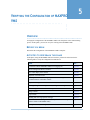
Revisions
Issue
Date
Description
1.0
March 8, 2012
New document
2.0
February, 2015
Updated for R310 Release
This page is intentionally left blank.
MAXPRO VMS R310
Table of Contents
Table of Contents
ABOUT THIS GUIDE . . . . . . . . . . . . . . . . . . . . . . . . . . . . . . . . . . . . . . . . . . . . . . 11
INTRODUCING MAXPRO® VMS R310 . . . . . . . . . . . . . . . . . . . . . . . . . . . . . . . . . . . . . .
SCOPE . . . . . . . . . . . . . . . . . . . . . . . . . . . . . . . . . . . . . . . . . . . . . . . . . . . . . . . . . . . . . . . .
INTENDED AUDIENCE . . . . . . . . . . . . . . . . . . . . . . . . . . . . . . . . . . . . . . . . . . . . . . . . . . . .
STRUCTURE OF THIS GUIDE . . . . . . . . . . . . . . . . . . . . . . . . . . . . . . . . . . . . . . . . . . . . . . .
TYPOGRAPHICAL CONVENTIONS . . . . . . . . . . . . . . . . . . . . . . . . . . . . . . . . . . . . . . . . . . . .
11
11
11
12
12
COMMISSIONING PLAN . . . . . . . . . . . . . . . . . . . . . . . . . . . . . . . . . . . . . . . . . . . 13
OVERVIEW . . . . . . . . . . . . . . . . . . . . . . . . . . . . . . . . . . . . . . . . . . . . . . . . . . . . . . . . . . . . 13
STEPS IN THE COMMISSIONING PROCESS . . . . . . . . . . . . . . . . . . . . . . . . . . . . . . . . . . . . . 13
SETTING UP THE SERVER AND CLIENT COMPUTERS . . . . . . . . . . . . . . . . . . . . . . . . . . . . . . . . . .
INSTALLING THE MAXPRO VMS R310 SOFTWARE IN THE SERVER AND CLIENT COMPUTERS
CONFIGURING THE MAXPRO VMS SYSTEM . . . . . . . . . . . . . . . . . . . . . . . . . . . . . . . . . . . . . . .
VERIFYING THE CONFIGURATION . . . . . . . . . . . . . . . . . . . . . . . . . . . . . . . . . . . . . . . . . . . . . . . .
13
13
14
15
SETTING UP THE CLIENT AND THE SERVER COMPUTERS . . . . . . . . . . . . . . . 17
OVERVIEW . . . . . . . . . . . . . . . . . . . . . . . . . . . . . . . . . . . . . . . . . . . . . . . . . . . . . . . . . . . . 17
BEFORE YOU BEGIN . . . . . . . . . . . . . . . . . . . . . . . . . . . . . . . . . . . . . . . . . . . . . . . . . . . . . . . . . . . 17
TASKS TO PERFORM IN THIS PHASE . . . . . . . . . . . . . . . . . . . . . . . . . . . . . . . . . . . . . . . . . . . . . . . 17
VIRTUAL MACHINE SPECIFICATIONS . . . . . . . . . . . . . . . . . . . . . . . . . . . . . . . . . . . . . . . . 18
USEFUL TIPS . . . . . . . . . . . . . . . . . . . . . . . . . . . . . . . . . . . . . . . . . . . . . . . . . . . . . . . . . . . . . . . . 19
HARDWARE SPECIFICATIONS . . . . . . . . . . . . . . . . . . . . . . . . . . . . . . . . . . . . . . . . . . . . . .
CONFIGURING THE MONITOR DISPLAY PROPERTIES . . . . . . . . . . . . . . . . . . . . . . . . . . . .
ABOUT SERIAL EXPANDER . . . . . . . . . . . . . . . . . . . . . . . . . . . . . . . . . . . . . . . . . . . . . . . .
ENABLING WINDOWS .NET 3.5 . . . . . . . . . . . . . . . . . . . . . . . . . . . . . . . . . . . . . . . . . . . .
20
25
25
27
INSTALLING THE MAXPRO VMS R310 SOFTWARE . . . . . . . . . . . . . . . . . . . 37
OVERVIEW . . . . . . . . . . . . . . . . . . . . . . . . . . . . . . . . . . . . . . . . . . . . . . . . . . . . . . . . . . . . 37
BEFORE YOU BEGIN . . . . . . . . . . . . . . . . . . . . . . . . . . . . . . . . . . . . . . . . . . . . . . . . . . . . . . . . . . . 37
SYSTEM REQUIREMENTS . . . . . . . . . . . . . . . . . . . . . . . . . . . . . . . . . . . . . . . . . . . . . . . . . . . . . . . 37
OPERATION SYSTEM SPECIFICATIONS FOR THE RECORDERS . . . . . . . . . . . . . . . . . . . . . . . . . . . 37
INSTALLING THE MAXPRO VMS SOFTWARE . . . . . . . . . . . . . . . . . . . . . . . . . . . . . . . . . 39
HOW TO INSTALL MAXPRO VMS . . . . . . . . . . . . . . . . . . . . . . . . . . . . . . . . . . . . . . . . . 39
COMPLETE INSTALLATION . . . . . . . . . . . . . . . . . . . . . . . . . . . . . . . . . . . . . . . . . . . . . . . . 45
BEFORE YOU BEGIN . . . . . . . . . . . . . . . . . . . . . . . . . . . . . . . . . . . . . . . . . . . . . . . . . . . . . . . . . . . 45
CUSTOM INSTALLATION . . . . . . . . . . . . . . . . . . . . . . . . . . . . . . . . . . . . . . . . . . . . . . . . . . 49
SERVER INSTALLATION . . . . . . . . . . . . . . . . . . . . . . . . . . . . . . . . . . . . . . . . . . . . . . . . . . . . . . . . 49
CLIENT INSTALLATION . . . . . . . . . . . . . . . . . . . . . . . . . . . . . . . . . . . . . . . . . . . . . . . . . . . . . . . . 55
VIDEO ANALYTICS SERVER INSTALLATION . . . . . . . . . . . . . . . . . . . . . . . . . . . . . . . . . . . 61
BEFORE YOU BEGIN . . . . . . . . . . . . . . . . . . . . . . . . . . . . . . . . . . . . . . . . . . . . . . . . . . . . . . . . . . . 61
AFTER INSTALLING MAXPRO VMS R310 . . . . . . . . . . . . . . . . . . . . . . . . . . . . . . . . . . . . . . . . 64
5
MAXPRO VMS R310
Table of Contents
REMOVING THE MAXPRO VMS R310 SOFTWARE . . . . . . . . . . . . . . . . . . . . . . . . . . . . . .65
BEFORE YOU BEGIN . . . . . . . . . . . . . . . . . . . . . . . . . . . . . . . . . . . . . . . . . . . . . . . . . . . . . . . . . . . 65
AFTER REMOVING MAXPRO VMS R310 . . . . . . . . . . . . . . . . . . . . . . . . . . . . . . . . . . . . . . . . . 71
SQL EXPRESS 2012 SCENARIOS . . . . . . . . . . . . . . . . . . . . . . . . . . . . . . . . . . . . . . . . . . . . .72
CLEANING THE SYSTEM . . . . . . . . . . . . . . . . . . . . . . . . . . . . . . . . . . . . . . . . . . . . . . . . . . . . . . . 73
MANUAL STEPS IF SQL CONNECTION FAILS . . . . . . . . . . . . . . . . . . . . . . . . . . . . . . . . . . . . . . . 75
CONFIGURING DEVICES AND SETTING UP A SITE . . . . . . . . . . . . . . . . . . . . . 77
BEFORE YOU BEGIN . . . . . . . . . . . . . . . . . . . . . . . . . . . . . . . . . . . . . . . . . . . . . . . . . . . . . . . . . . . 77
FIREWALL SETTINGS . . . . . . . . . . . . . . . . . . . . . . . . . . . . . . . . . . . . . . . . . . . . . . . . . . . . . .77
SERVER SIDE CONFIGURATION . . . . . . . . . . . . . . . . . . . . . . . . . . . . . . . . . . . . . . . . . . . . . . . . . .
RECORDERS . . . . . . . . . . . . . . . . . . . . . . . . . . . . . . . . . . . . . . . . . . . . . . . . . . . . . . . . . . . . . . . . .
OTHER RECORDERS . . . . . . . . . . . . . . . . . . . . . . . . . . . . . . . . . . . . . . . . . . . . . . . . . . . . . . . . . . .
CLIENT CONFIGURATION . . . . . . . . . . . . . . . . . . . . . . . . . . . . . . . . . . . . . . . . . . . . . . . . . . . . . .
ULTRAKEY . . . . . . . . . . . . . . . . . . . . . . . . . . . . . . . . . . . . . . . . . . . . . . . . . . . . . . . . . . . . . . . . .
77
78
78
79
79
CONFIGURING MAXPRO VMS . . . . . . . . . . . . . . . . . . . . . . . . . . . . . . . . . . . . . . . . . . . . .80
SETTING UP A SITE USING CONFIGURATOR . . . . . . . . . . . . . . . . . . . . . . . . . . . . . . . . . . . .82
ADDING SITES . . . . . . . . . . . . . . . . . . . . . . . . . . . . . . . . . . . . . . . . . . . . . . . . . . . . . . . . . . . . . . .
ADDING WORKSTATIONS . . . . . . . . . . . . . . . . . . . . . . . . . . . . . . . . . . . . . . . . . . . . . . . . . . . . . .
ADDING PARTITIONS . . . . . . . . . . . . . . . . . . . . . . . . . . . . . . . . . . . . . . . . . . . . . . . . . . . . . . . . . .
ADDING ROLES AND USERS . . . . . . . . . . . . . . . . . . . . . . . . . . . . . . . . . . . . . . . . . . . . . . . . . . . .
ADDING CONTACT GROUP AND CONTACTS . . . . . . . . . . . . . . . . . . . . . . . . . . . . . . . . . . . . . . . .
ADDING EVENT GROUPS . . . . . . . . . . . . . . . . . . . . . . . . . . . . . . . . . . . . . . . . . . . . . . . . . . . . . . .
ADDING RECORDER GROUPS . . . . . . . . . . . . . . . . . . . . . . . . . . . . . . . . . . . . . . . . . . . . . . . . . . . .
ADDING SERIAL PORTS . . . . . . . . . . . . . . . . . . . . . . . . . . . . . . . . . . . . . . . . . . . . . . . . . . . . . . . .
ADDING ANALYTICS . . . . . . . . . . . . . . . . . . . . . . . . . . . . . . . . . . . . . . . . . . . . . . . . . . . . . . . . . .
ADDING RECORDERS . . . . . . . . . . . . . . . . . . . . . . . . . . . . . . . . . . . . . . . . . . . . . . . . . . . . . . . . . .
ADDING SWITCHERS . . . . . . . . . . . . . . . . . . . . . . . . . . . . . . . . . . . . . . . . . . . . . . . . . . . . . . . . . .
ADDING VIDEO INPUTS . . . . . . . . . . . . . . . . . . . . . . . . . . . . . . . . . . . . . . . . . . . . . . . . . . . . . . . .
ADDING VIDEO OUTPUTS . . . . . . . . . . . . . . . . . . . . . . . . . . . . . . . . . . . . . . . . . . . . . . . . . . . . . .
ADDING RELAYS . . . . . . . . . . . . . . . . . . . . . . . . . . . . . . . . . . . . . . . . . . . . . . . . . . . . . . . . . . . . .
ADDING ALARM INPUTS . . . . . . . . . . . . . . . . . . . . . . . . . . . . . . . . . . . . . . . . . . . . . . . . . . . . . . .
ADDING LOGICAL CAMERAS . . . . . . . . . . . . . . . . . . . . . . . . . . . . . . . . . . . . . . . . . . . . . . . . . . . .
ADDING SEQUENCES . . . . . . . . . . . . . . . . . . . . . . . . . . . . . . . . . . . . . . . . . . . . . . . . . . . . . . . . . .
ADDING SYSTEM MACROS . . . . . . . . . . . . . . . . . . . . . . . . . . . . . . . . . . . . . . . . . . . . . . . . . . . . .
ADDING JOYSTICK CONTROLLERS. . . . . . . . . . . . . . . . . . . . . . . . . . . . . . . . . . . . . . . . . . . . . . . .
ADDING INTERCEPT KEYS . . . . . . . . . . . . . . . . . . . . . . . . . . . . . . . . . . . . . . . . . . . . . . . . . . . . . .
SCHEDULING . . . . . . . . . . . . . . . . . . . . . . . . . . . . . . . . . . . . . . . . . . . . . . . . . . . . . . . . . . . . . . . .
82
82
82
82
82
82
83
83
83
83
83
83
83
83
83
84
84
84
84
84
84
RECORDERS . . . . . . . . . . . . . . . . . . . . . . . . . . . . . . . . . . . . . . . . . . . . . . . . . . . . . . . . . . . .85
ADDING A RECORDER . . . . . . . . . . . . . . . . . . . . . . . . . . . . . . . . . . . . . . . . . . . . . . . . . . . . . . . . . 85
ADVANCED SETTINGS FOR IP ENGINE . . . . . . . . . . . . . . . . . . . . . . . . . . . . . . . . . . . . . . . . . . . . 92
DISCOVERING DEVICES . . . . . . . . . . . . . . . . . . . . . . . . . . . . . . . . . . . . . . . . . . . . . . . . . . . . . . . . 95
6
MAXPRO VMS R310
Table of Contents
ASSOCIATING PARTITIONS TO THE RECORDER . . . . . . . . . . . . . . . . . . . . . . . . . . . . . . . . . . . . . . 99
ASSOCIATING EVENTS AND EVENT ATTRIBUTES TO A RECORDER . . . . . . . . . . . . . . . . . . . . . 100
FILTERING AND GROUPING THE RECORDERS . . . . . . . . . . . . . . . . . . . . . . . . . . . . . . . . . . . . . . 110
SORTING RECORDER . . . . . . . . . . . . . . . . . . . . . . . . . . . . . . . . . . . . . . . . . . . . . . . . . . . . . . . . . 114
UPDATING A RECORDER . . . . . . . . . . . . . . . . . . . . . . . . . . . . . . . . . . . . . . . . . . . . . . . . . . . . . . 116
DELETING A RECORDER . . . . . . . . . . . . . . . . . . . . . . . . . . . . . . . . . . . . . . . . . . . . . . . . . . . . . . 116
VIDEO INPUTS . . . . . . . . . . . . . . . . . . . . . . . . . . . . . . . . . . . . . . . . . . . . . . . . . . . . . . . . . 117
ADDING VIDEO INPUTS . . . . . . . . . . . . . . . . . . . . . . . . . . . . . . . . . . . . . . . . . . . . . . . . . . . . . . .
ADDING A CAMERA. . . . . . . . . . . . . . . . . . . . . . . . . . . . . . . . . . . . . . . . . . . . . . . . . . . . . . . . . .
ASSOCIATING EVENTS AND EVENT ATTRIBUTES TO A VIDEO INPUT . . . . . . . . . . . . . . . . . . . .
ASSOCIATING PARTITIONS TO VIDEO INPUTS . . . . . . . . . . . . . . . . . . . . . . . . . . . . . . . . . . . . . .
ASSOCIATING ANALYTICS . . . . . . . . . . . . . . . . . . . . . . . . . . . . . . . . . . . . . . . . . . . . . . . . . . . . .
FILTERING AND GROUPING THE VIDEOINPUT(S) . . . . . . . . . . . . . . . . . . . . . . . . . . . . . . . . . . .
SORTING VIDEO INPUT(S) . . . . . . . . . . . . . . . . . . . . . . . . . . . . . . . . . . . . . . . . . . . . . . . . . . . . .
UPDATING A VIDEO INPUT . . . . . . . . . . . . . . . . . . . . . . . . . . . . . . . . . . . . . . . . . . . . . . . . . . . .
DELETING A VIDEO INPUT . . . . . . . . . . . . . . . . . . . . . . . . . . . . . . . . . . . . . . . . . . . . . . . . . . . .
ADDING A VIDEO INPUT DEVICE . . . . . . . . . . . . . . . . . . . . . . . . . . . . . . . . . . . . . . . . . . . . . . .
ADDING A VIDEO INPUT DEVICE (DIGITAL INPUT TRUNK) . . . . . . . . . . . . . . . . . . . . . . . . . . .
117
119
149
154
155
155
160
161
161
162
162
VIDEO OUTPUTS . . . . . . . . . . . . . . . . . . . . . . . . . . . . . . . . . . . . . . . . . . . . . . . . . . . . . . . 164
ADDING VIDEO OUTPUTS . . . . . . . . . . . . . . . . . . . . . . . . . . . . . . . . . . . . . . . . . . . . . . . . . . . . . 164
ADDING MONITORS . . . . . . . . . . . . . . . . . . . . . . . . . . . . . . . . . . . . . . . . . . . . . . . . . . . . . . . . . . 166
ADDING A VIDEO OUTPUT DEVICE (STANDARD DEVICE/SMART DEVICE/VCR/ STANDBY VCR) 169
ADDING A VIDEO OUTPUT DEVICE (TRUNK) . . . . . . . . . . . . . . . . . . . . . . . . . . . . . . . . . . . . . . 170
ADDING A VIDEO OUTPUT DEVICE (DIGITAL OUTPUT TRUNK). . . . . . . . . . . . . . . . . . . . . . . . 171
DELETING A VIDEO OUTPUT DEVICE . . . . . . . . . . . . . . . . . . . . . . . . . . . . . . . . . . . . . . . . . . . . 173
UPDATING A VIDEO OUTPUT DEVICE . . . . . . . . . . . . . . . . . . . . . . . . . . . . . . . . . . . . . . . . . . . . 173
LOCKING THE DISPLAY ON THE MONITOR . . . . . . . . . . . . . . . . . . . . . . . . . . . . . . . . . . . . . . . . 173
ASSOCIATING PARTITIONS TO VIDEO OUTPUTS . . . . . . . . . . . . . . . . . . . . . . . . . . . . . . . . . . . . 173
ASSOCIATING VIDEO OUTPUTS TO EVENT GROUPS . . . . . . . . . . . . . . . . . . . . . . . . . . . . . . . . . 174
ASSOCIATING VIDEO OUTPUTS TO JOYSTICK CONTROLLERS . . . . . . . . . . . . . . . . . . . . . . . . . . 174
JOYSTICK CONTROLLERS . . . . . . . . . . . . . . . . . . . . . . . . . . . . . . . . . . . . . . . . . . . . . . . . 175
CONFIGURING JOYSTICK CONTROLLER . . . . . . . . . . . . . . . . . . . . . . . . . . . . . . . . . . . . . . . . . . .
CONNECTING THE KEYBOARD TO MAXPRO VMS . . . . . . . . . . . . . . . . . . . . . . . . . . . . . . . . .
SIGN ON AND SIGN OFF . . . . . . . . . . . . . . . . . . . . . . . . . . . . . . . . . . . . . . . . . . . . . . . . . . . . . .
CONFIGURING THE SIGN ON AND SIGN OFF FEATURE . . . . . . . . . . . . . . . . . . . . . . . . . . . . . . .
UPDATING A JOYSTICK CONTROLLER . . . . . . . . . . . . . . . . . . . . . . . . . . . . . . . . . . . . . . . . . . . .
175
175
176
176
177
SWITCHERS . . . . . . . . . . . . . . . . . . . . . . . . . . . . . . . . . . . . . . . . . . . . . . . . . . . . . . . . . . . 179
ADDING A SWITCHER . . . . . . . . . . . . . . . . . . . . . . . . . . . . . . . . . . . . . . . . . . . . . . . . . . . . . . . .
UPDATING A SWITCHER . . . . . . . . . . . . . . . . . . . . . . . . . . . . . . . . . . . . . . . . . . . . . . . . . . . . . . .
DELETING A SWITCHER . . . . . . . . . . . . . . . . . . . . . . . . . . . . . . . . . . . . . . . . . . . . . . . . . . . . . . .
ASSOCIATING PARTITIONS TO SWITCHER . . . . . . . . . . . . . . . . . . . . . . . . . . . . . . . . . . . . . . . . .
ASSOCIATING EVENTS TO SWITCHER . . . . . . . . . . . . . . . . . . . . . . . . . . . . . . . . . . . . . . . . . . . .
179
184
184
185
185
7
MAXPRO VMS R310
Table of Contents
RELAYS . . . . . . . . . . . . . . . . . . . . . . . . . . . . . . . . . . . . . . . . . . . . . . . . . . . . . . . . . . . . . . .188
ADDING THE RELAY. . . . . . . . . . . . . . . . . . . . . . . . . . . . . . . . . . . . . . . . . . . . . . . . . . . . . . . . . . 188
DELETING THE RELAY . . . . . . . . . . . . . . . . . . . . . . . . . . . . . . . . . . . . . . . . . . . . . . . . . . . . . . . . 193
UPDATING THE RELAY . . . . . . . . . . . . . . . . . . . . . . . . . . . . . . . . . . . . . . . . . . . . . . . . . . . . . . . 194
ALARM INPUTS . . . . . . . . . . . . . . . . . . . . . . . . . . . . . . . . . . . . . . . . . . . . . . . . . . . . . . . . .195
DELETING THE ALARM INPUT . . . . . . . . . . . . . . . . . . . . . . . . . . . . . . . . . . . . . . . . . . . . . . . . . . 203
UPDATING THE ALARM INPUT . . . . . . . . . . . . . . . . . . . . . . . . . . . . . . . . . . . . . . . . . . . . . . . . . . 203
CONTACT GROUP . . . . . . . . . . . . . . . . . . . . . . . . . . . . . . . . . . . . . . . . . . . . . . . . . . . . . . .204
DELETING THE CONTACT GROUP . . . . . . . . . . . . . . . . . . . . . . . . . . . . . . . . . . . . . . . . . . . . . . . 205
UPDATING THE CONTACT GROUP . . . . . . . . . . . . . . . . . . . . . . . . . . . . . . . . . . . . . . . . . . . . . . . 205
CONTACTS . . . . . . . . . . . . . . . . . . . . . . . . . . . . . . . . . . . . . . . . . . . . . . . . . . . . . . . . . . . .206
ADDING A CONTACT . . . . . . . . . . . . . . . . . . . . . . . . . . . . . . . . . . . . . . . . . . . . . . . . . . . . . . . . . 206
USERS . . . . . . . . . . . . . . . . . . . . . . . . . . . . . . . . . . . . . . . . . . . . . . . . . . . . . . . . . . . . . . . .208
ADDING A USER . . . . . . . . . . . . . . . . . . . . . . . . . . . . . . . . . . . . . . . . . . . . . . . . . . . . . . . . . . . .
DISCOVERING AND IMPORTING USERS . . . . . . . . . . . . . . . . . . . . . . . . . . . . . . . . . . . . . . . . . . .
UPDATING A USER . . . . . . . . . . . . . . . . . . . . . . . . . . . . . . . . . . . . . . . . . . . . . . . . . . . . . . . . . . .
DELETING A USER . . . . . . . . . . . . . . . . . . . . . . . . . . . . . . . . . . . . . . . . . . . . . . . . . . . . . . . . . . .
208
220
221
221
ROLES . . . . . . . . . . . . . . . . . . . . . . . . . . . . . . . . . . . . . . . . . . . . . . . . . . . . . . . . . . . . . . . .222
ADDING A ROLE . . . . . . . . . . . . . . . . . . . . . . . . . . . . . . . . . . . . . . . . . . . . . . . . . . . . . . . . . . . . . 222
UPDATING A ROLE . . . . . . . . . . . . . . . . . . . . . . . . . . . . . . . . . . . . . . . . . . . . . . . . . . . . . . . . . . . 231
DELETING A ROLE . . . . . . . . . . . . . . . . . . . . . . . . . . . . . . . . . . . . . . . . . . . . . . . . . . . . . . . . . . . 231
SEQUENCES . . . . . . . . . . . . . . . . . . . . . . . . . . . . . . . . . . . . . . . . . . . . . . . . . . . . . . . . . . . .233
CREATING A SEQUENCE . . . . . . . . . . . . . . . . . . . . . . . . . . . . . . . . . . . . . . . . . . . . . . . . . . . . . . 233
UPDATING A SEQUENCE . . . . . . . . . . . . . . . . . . . . . . . . . . . . . . . . . . . . . . . . . . . . . . . . . . . . . . 235
DELETING A SEQUENCE . . . . . . . . . . . . . . . . . . . . . . . . . . . . . . . . . . . . . . . . . . . . . . . . . . . . . . . 235
ANALYTICS . . . . . . . . . . . . . . . . . . . . . . . . . . . . . . . . . . . . . . . . . . . . . . . . . . . . . . . . . . . .236
HONEYWELL VIDEO ANALYTICS (ACTIVEYE) REPORTING TOOL. . . . . . . . . . . . . . . . . . . . . . .
HONEYWELL VIDEO ANALYTICS (ACTIVEYE) ALARM MANAGEMENT . . . . . . . . . . . . . . . . . .
HONEYWELL VIDEO ANALYTICS (ACTIVEYE) CONFIGURATION TOOL . . . . . . . . . . . . . . . . . .
HONEYWELL VIDEO ANALYTICS (ACTIVEYE) FORENSICS TOOL . . . . . . . . . . . . . . . . . . . . . . .
HONEYWELL VIDEO ANALYTICS (ACTIVEYE) LIVE MONITORING STATION . . . . . . . . . . . . . .
HONEYWELL VIDEO ANALYTICS (ACTIVEYE) USER CONFIGURATION . . . . . . . . . . . . . . . . . .
ADDING AN ANALYTICS SERVER . . . . . . . . . . . . . . . . . . . . . . . . . . . . . . . . . . . . . . . . . . . . . . .
236
236
236
237
237
237
237
PARTITIONS . . . . . . . . . . . . . . . . . . . . . . . . . . . . . . . . . . . . . . . . . . . . . . . . . . . . . . . . . . . .242
ADDING A PARTITION . . . . . . . . . . . . . . . . . . . . . . . . . . . . . . . . . . . . . . . . . . . . . . . . . . . . . . . . 242
DELETING A PARTITION . . . . . . . . . . . . . . . . . . . . . . . . . . . . . . . . . . . . . . . . . . . . . . . . . . . . . . . 243
WORKSTATIONS . . . . . . . . . . . . . . . . . . . . . . . . . . . . . . . . . . . . . . . . . . . . . . . . . . . . . . . .244
ADDING A WORKSTATION . . . . . . . . . . . . . . . . . . . . . . . . . . . . . . . . . . . . . . . . . . . . . . . . . . . . . 244
DELETING A WORKSTATION . . . . . . . . . . . . . . . . . . . . . . . . . . . . . . . . . . . . . . . . . . . . . . . . . . . 244
SITE . . . . . . . . . . . . . . . . . . . . . . . . . . . . . . . . . . . . . . . . . . . . . . . . . . . . . . . . . . . . . . . . . .246
ADDING A SITE . . . . . . . . . . . . . . . . . . . . . . . . . . . . . . . . . . . . . . . . . . . . . . . . . . . . . . . . . . . . . 246
DELETING A SITE . . . . . . . . . . . . . . . . . . . . . . . . . . . . . . . . . . . . . . . . . . . . . . . . . . . . . . . . . . . . 246
8
MAXPRO VMS R310
Table of Contents
EVENT GROUP . . . . . . . . . . . . . . . . . . . . . . . . . . . . . . . . . . . . . . . . . . . . . . . . . . . . . . . . . 247
ADDING AN EVENT GROUP . . . . . . . . . . . . . . . . . . . . . . . . . . . . . . . . . . . . . . . . . . . . . . . . . . . . 247
DELETING AN EVENT GROUP . . . . . . . . . . . . . . . . . . . . . . . . . . . . . . . . . . . . . . . . . . . . . . . . . . 247
INTERCEPT KEYS . . . . . . . . . . . . . . . . . . . . . . . . . . . . . . . . . . . . . . . . . . . . . . . . . . . . . . . 249
ADDING INTERCEPT KEY . . . . . . . . . . . . . . . . . . . . . . . . . . . . . . . . . . . . . . . . . . . . . . . . . . . . . 249
UPDATING INTERCEPT KEYS . . . . . . . . . . . . . . . . . . . . . . . . . . . . . . . . . . . . . . . . . . . . . . . . . . . 250
DELETING INTERCEPT KEYS . . . . . . . . . . . . . . . . . . . . . . . . . . . . . . . . . . . . . . . . . . . . . . . . . . . 250
LOGICAL CAMERA . . . . . . . . . . . . . . . . . . . . . . . . . . . . . . . . . . . . . . . . . . . . . . . . . . . . . 252
ADDING A LOGICAL CAMERA . . . . . . . . . . . . . . . . . . . . . . . . . . . . . . . . . . . . . . . . . . . . . . . . . . 252
DELETING A LOGICAL CAMERA . . . . . . . . . . . . . . . . . . . . . . . . . . . . . . . . . . . . . . . . . . . . . . . . 255
UPDATING LOGICAL CAMERAS . . . . . . . . . . . . . . . . . . . . . . . . . . . . . . . . . . . . . . . . . . . . . . . . . 255
SYSTEM MACROS . . . . . . . . . . . . . . . . . . . . . . . . . . . . . . . . . . . . . . . . . . . . . . . . . . . . . . 256
ADDING A SYSTEM MACRO . . . . . . . . . . . . . . . . . . . . . . . . . . . . . . . . . . . . . . . . . . . . . . . . . . . 256
EXECUTING A SYSTEM MACRO . . . . . . . . . . . . . . . . . . . . . . . . . . . . . . . . . . . . . . . . . . . . . . . . . 256
DELETING A SYSTEM MACRO . . . . . . . . . . . . . . . . . . . . . . . . . . . . . . . . . . . . . . . . . . . . . . . . . . 257
RECORDER GROUPS . . . . . . . . . . . . . . . . . . . . . . . . . . . . . . . . . . . . . . . . . . . . . . . . . . . . 258
ASSOCIATING RECORDER TO RECORDER GROUPS . . . . . . . . . . . . . . . . . . . . . . . . . . . . . . . . . .
DISASSOCIATING RECORDERS FROM THE RECORDER GROUPS . . . . . . . . . . . . . . . . . . . . . . . . .
UPDATING RECORDER GROUP . . . . . . . . . . . . . . . . . . . . . . . . . . . . . . . . . . . . . . . . . . . . . . . . .
DELETING RECORDER GROUP . . . . . . . . . . . . . . . . . . . . . . . . . . . . . . . . . . . . . . . . . . . . . . . . . .
258
260
260
261
TRINITY CONTROLLER . . . . . . . . . . . . . . . . . . . . . . . . . . . . . . . . . . . . . . . . . . . . . . . . . . 262
SERIAL PORT . . . . . . . . . . . . . . . . . . . . . . . . . . . . . . . . . . . . . . . . . . . . . . . . . . . . . . . . . . 268
ADDING A SERIAL PORT . . . . . . . . . . . . . . . . . . . . . . . . . . . . . . . . . . . . . . . . . . . . . . . . . . . . . . 268
UPDATING A SERIAL PORT . . . . . . . . . . . . . . . . . . . . . . . . . . . . . . . . . . . . . . . . . . . . . . . . . . . . 271
DELETING A SERIAL PORT . . . . . . . . . . . . . . . . . . . . . . . . . . . . . . . . . . . . . . . . . . . . . . . . . . . . 271
USER DEFINED EVENTS . . . . . . . . . . . . . . . . . . . . . . . . . . . . . . . . . . . . . . . . . . . . . . . . . 272
EVENT ASSOCIATION . . . . . . . . . . . . . . . . . . . . . . . . . . . . . . . . . . . . . . . . . . . . . . . . . . . 274
MIGRATION . . . . . . . . . . . . . . . . . . . . . . . . . . . . . . . . . . . . . . . . . . . . . . . . . . . . . . . . . . . 276
EXPORTING THE FILES . . . . . . . . . . . . . . . . . . . . . . . . . . . . . . . . . . . . . . . . . . . . . . . . . . . . . . . 276
IMPORTING THE DATABASE . . . . . . . . . . . . . . . . . . . . . . . . . . . . . . . . . . . . . . . . . . . . . . . . . . . 276
EQUIP SERIES CAMERA . . . . . . . . . . . . . . . . . . . . . . . . . . . . . . . . . . . . . . . . . . . . . . . . . . 277
SCHEDULER . . . . . . . . . . . . . . . . . . . . . . . . . . . . . . . . . . . . . . . . . . . . . . . . . . . . . . . . . . . 281
UPDATING A SCHEDULER . . . . . . . . . . . . . . . . . . . . . . . . . . . . . . . . . . . . . . . . . . . . . . . . . . . . . 281
JOBS . . . . . . . . . . . . . . . . . . . . . . . . . . . . . . . . . . . . . . . . . . . . . . . . . . . . . . . . . . . . . . . . 285
ADDING JOBS . . . . . . . . . . . . . . . . . . . . . . . . . . . . . . . . . . . . . . . . . . . . . . . . . . . . . . . . . . . . . . 285
ALARM NOTIFICATION . . . . . . . . . . . . . . . . . . . . . . . . . . . . . . . . . . . . . . . . . . . . . . . . . . 288
SMTP SERVER SETTINGS . . . . . . . . . . . . . . . . . . . . . . . . . . . . . . . . . . . . . . . . . . . . . . . . 291
CREATING AN EMAIL TEMPLATE . . . . . . . . . . . . . . . . . . . . . . . . . . . . . . . . . . . . . . . . . . 292
VERIFYING THE CONFIGURATION OF MAXPRO VMS . . . . . . . . . . . . . . . . 301
OVERVIEW . . . . . . . . . . . . . . . . . . . . . . . . . . . . . . . . . . . . . . . . . . . . . . . . . . . . . . . . . . . 301
BEFORE YOU BEGIN . . . . . . . . . . . . . . . . . . . . . . . . . . . . . . . . . . . . . . . . . . . . . . . . . . . . . . . . . . 301
ACTIVITIES TO PERFORM IN THIS PHASE . . . . . . . . . . . . . . . . . . . . . . . . . . . . . . . . . . . . . . . . . . 301
9
MAXPRO VMS R310
Table of Contents
CHECKING THE CONNECTION WITH MAXPRO VMS SERVER . . . . . . . . . . . . . . . . . . . . .303
CHECKING THE DEVICE LISTING IN THE DEVICES WINDOW . . . . . . . . . . . . . . . . . . . . . .304
CHECKING THE LIVE VIDEO FROM CAMERAS . . . . . . . . . . . . . . . . . . . . . . . . . . . . . . . . .306
CHECKING THE PLAYBACK OF RECORDED VIDEO . . . . . . . . . . . . . . . . . . . . . . . . . . . . . .307
CHECKING THE BOOKMARK FEATURE . . . . . . . . . . . . . . . . . . . . . . . . . . . . . . . . . . . . . . .309
CHECKING THE PLAYBACK LOOP IN THE TIMELINE WINDOW . . . . . . . . . . . . . . . . . . . . .310
CHECKING THE PANNING, TILTING, AND ZOOMING . . . . . . . . . . . . . . . . . . . . . . . . . . . . .311
CHECKING FOR ACKNOWLEDGEMENT AND CLEARING OF ALARMS . . . . . . . . . . . . . . . .312
CHECKING FOR THE CREATION OF IMAGES . . . . . . . . . . . . . . . . . . . . . . . . . . . . . . . . . . .314
CHECKING THE CREATION OF CLIPS . . . . . . . . . . . . . . . . . . . . . . . . . . . . . . . . . . . . . . . .315
CHECKING THE SENDING AND RECEIVING OF OPERATOR MESSAGES . . . . . . . . . . . . . . .316
CHECKING THE SURROUNDING CAMERAS FEATURE . . . . . . . . . . . . . . . . . . . . . . . . . . . .317
CHECKING THE SAVING THE SALVO LAYOUT USING THE SALVO VIEW FEATURE . . . . .318
CHECKING THE DEVICE LISTING IN MY DEVICES WINDOW . . . . . . . . . . . . . . . . . . . . . .319
CHECKING THE SEARCH FOR RECORDED VIDEO . . . . . . . . . . . . . . . . . . . . . . . . . . . . . . .320
CHECKING THE GENERATION OF EVENT HISTORY AND OPERATOR LOG REPORT . . . . . .321
UPGRADING TO MAXPRO VMS R310 . . . . . . . . . . . . . . . . . . . . . . . . . . . . 323
OVERVIEW . . . . . . . . . . . . . . . . . . . . . . . . . . . . . . . . . . . . . . . . . . . . . . . . . . . . . . . . . . . .323
BEFORE YOU BEGIN . . . . . . . . . . . . . . . . . . . . . . . . . . . . . . . . . . . . . . . . . . . . . . . . . . . . . . . . . . 323
UPGRADING MAXPRO VMS R300 TO MAXPRO VMS R310 . . . . . . . . . . . . . . . . . . .324
BEFORE YOU BEGIN . . . . . . . . . . . . . . . . . . . . . . . . . . . . . . . . . . . . . . . . . . . . . . . . . . . . . . . . . . 324
UPGRADING MAXPRO VMS R240 TO MAXPRO VMS R300 . . . . . . . . . . . . . . . . . . .330
10
ABOUT THIS GUIDE
.....
...................................
INTRODUCING MAXPRO® VMS R310
.................................................................
MAXPRO® Video Management System R310 (MAXPRO® VMS R310) is an enterpriseclass video management and hybrid solution. It enables you to perform various surveillance
operations on traditional analog, network and IP based video equipment in the same
surveillance network. You can deploy thousands of cameras in number of locations, and add
many video devices such as recorders and monitors.
SCOPE
.................................................................
This guide helps you in:
•
Setting up the hardware for the MAXPRO VMS system
•
Installing and uninstalling the MAXPRO VMS software
•
Commissioning the MAXPRO VMS system
•
Verifying the MAXPRO VMS system after the commissioning process
•
Upgrading from previous versions of MAXPRO VMS to MAXPRO VMS R310.
INTENDED AUDIENCE
.................................................................
This guide is intended for the field and commissioning engineers of MAXPRO VMS system.
MAXPRO VMS R310 Commissioning and Installation Guide
11
ABOUT THIS GUIDE
Structure of this Guide
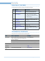
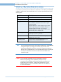
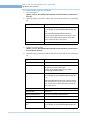
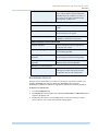
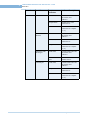
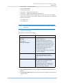
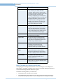
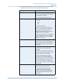
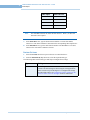
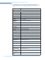
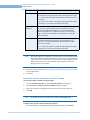
STRUCTURE OF THIS GUIDE
.................................................................
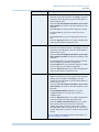
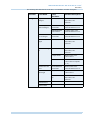
The following table describes the contents of each chapter in this guide.
No
Chapter
Description
1
Commissioning Plan
Description of the process involved in
commissioning the MAXPRO VMS.
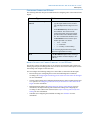
2
Setting up the Client and the
Server Computers
•
Hardware specifications for MAXPRO
VMS server and client computers.
•
Procedures for configuring the monitor
display properties.
•
Steps for installing the serial expander.
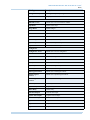
3
Installing the MAXPRO VMS
R310 Software
Procedure for installing MAXPRO VMS
R310 software.
4
Configuring devices and
Setting up a Site
Configure the MAXPRO VMS.
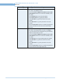
5
Verifying the Configuration
of MAXPRO VMS
Steps to verify the configuration of
MAXPRO VMS.
6
Upgrading to MAXPRO VMS
R310
Procedures to upgrade from previous
versions for MAXPRO VMS to MAXPRO
VMS R310.
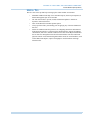
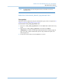
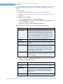
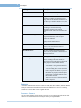
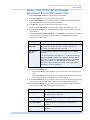
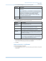
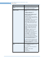
TYPOGRAPHICAL CONVENTIONS
.................................................................
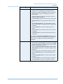
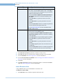
This guide uses the conventions listed in the following table.
12
Font
What it represents
Example
Swiss721 BT
Words or characters that you must type. The word
“enter” is used if you must type text and then press
the Enter or Return key.
Enter the password.
Menu titles and other items you select
Double-click Open from the File menu.
Buttons you click to perform actions
Click Exit to close the program.
Trebuchet MS
Heading
Installation
Swiss721 BT
(Bold Italic)
Cross-reference to external source
Refer to the System Administrator
Guide.
Swiss721 BT
(Italic)
Cross-reference within the guide
See Installation.
MAXPRO VMS R310 Commissioning and Installation Guide
1
COMMISSIONING PLAN
.....
...................................
OVERVIEW
.................................................................
Commissioning is the process of installing, configuring, and setting up the MAXPRO VMS
hardware and software. At the end of the commissioning process, the MAXPRO VMS system
is equipped for use by operators to perform surveillance operations. The steps in the
commissioning process must be performed one after the other for successful deployment of
MAXPRO VMS system.
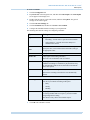
STEPS IN THE COMMISSIONING PROCESS
.................................................................
The process of commissioning consists of the following phases:
•
•
•
•
Setting up the Server and Client Computers.
Installing the MAXPRO VMS R310 Software in the Server and Client Computers.
Configuring the MAXPRO VMS System.
Verifying the Configuration.
SETTING UP THE SERVER AND CLIENT COMPUTERS
Setting up the server and client computers involve:
•
Determining the number of server and client computers at the location and ensuring that
they meet the minimum hardware requirements such as processor type and memory size.
•
to the computers after ensuring that they meet the hardware requirements. You can
connect up to four monitors to each computer. After , configure the monitor display
properties.
•
Installing the serial expander, if switchers, serial keyboards (Ultrakey), Protocol Interface
Translators (PIT), and other serial devices are used at the location.
Note:
See the chapter Setting up the Client and the Server Computers for information
on hardware requirements, how to connect the monitors to the computers, how to
configure the display properties, and how to install the serial expander.
INSTALLING THE MAXPRO VMS R310 SOFTWARE IN THE
SERVER AND CLIENT COMPUTERS
Installing the software involves:
MAXPRO VMS R310 Commissioning and Installation Guide
13
1
COMMISSIONING PLAN
Steps in the Commissioning Process
•
Ensuring that the server and client computers meet the minimum software requirements
such as operating system and anti virus software.
•
Installing the MAXPRO VMS R310 software.
Note:
See the chapter Installing the MAXPRO VMS R310 Software for information on
software requirements and installation instructions for the MAXPRO VMS R310
software.
CONFIGURING THE MAXPRO VMS SYSTEM
In this phase, you need to configure the MAXPRO VMS through the user interface. Before
you start configuring, perform the following:
•
Determine the number of sites to add in the MAXPRO VMS system. A default site is
available in MAXPRO VMS. Typically, a site is a geographical group of cameras or
similar cameras and can be used to logically group cameras.
•
Determine the number of partitions and event groups to be created for each site. A default
global partition is automatically created when you add a site in MAXPRO VMS.
Partitions and event groups are used to limit access to cameras and events.
•
Ensure that the recorders and other video devices such as cameras and streamers are
powered on and connected to the network.
•
Determine the IP addresses of the recorders and streamers. The IP addresses are required
to add the devices to the MAXPRO VMS system.
•
Determine to which site each recorder, camera, monitor, and switcher needs to be
associated.
•
Determine to which event group and partition each recorder, camera, switcher, and
monitor needs to be associated.
•
Determine the roles of users for each site. You need to create roles and define privileges
for them while configuring the MAXPRO VMS system.
•
Determine the number of users for each site. You need to create users and associate them
to roles while configuring the MAXPRO VMS system. MAXPRO can also use Windows
System users discoverable through Active directory
•
Determine which partitions, event groups, client workstations, and joystick controllers
(Ultrakey keyboard) each user can access.
Note:
14
See the chapter Configuring devices and Setting up a Site for information on how
to configure the MAXPRO VMS system.
MAXPRO VMS R310 Commissioning and Installation Guide
. . . . .
COMMISSIONING PLAN
Steps in the Commissioning Process
VERIFYING THE CONFIGURATION
•
Verifying the configuration involves checking whether the surveillance operations can be
performed using MAXPRO VMS software. Surveillance operations include, viewing the
live video, performing the pan, tilt, and zoom on the video, and starting the video
recording.
Note:
See the chapter Verifying the Configuration of MAXPRO VMS for information on
how to perform the verification.
MAXPRO VMS R310 Commissioning and Installation Guide
15
1
COMMISSIONING PLAN
Steps in the Commissioning Process
This page is intentionally left blank
16
MAXPRO VMS R310 Commissioning and Installation Guide
2
SETTING UP THE CLIENT AND THE SERVER
COMPUTERS
.....
...................................
OVERVIEW
.................................................................
Setting up the server and client computers is the first phase in the commissioning process.
BEFORE YOU BEGIN
Determine the following at the location:
•
Number of server and client computers
•
Hardware configuration of the computers
•
Number of serial devices such as joystick controllers (Ultrakey keyboard), switchers,
PITs, and other devices
TASKS TO PERFORM IN THIS PHASE
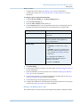
The following table lists the activities that are performed in this phase.
Tasks
See the section...
Specifications for virtual server solution
Virtual Machine Specifications
Ensure that the hardware configuration of
the server and client computers meet the
minimum specifications.
Hardware Specifications
Connect the monitors, keyboard, and mouse
to the server and client computers.
Configuring the Monitor Display
Properties
Configure the monitor display properties.
Configuring the Monitor Display
Properties.
Install the serial expander in the server to
connect serial devices.
About Serial Expander
MAXPRO VMS R310 Commissioning and Installation Guide
17
2
SETTING UP THE CLIENT AND THE SERVER COMPUTERS
Virtual Machine Specifications
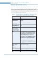
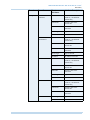
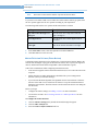
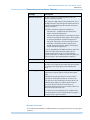
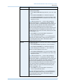
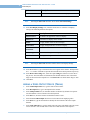
VIRTUAL MACHINE SPECIFICATIONS
.................................................................
If you choose to provide your own virtual server solution for use with Honeywell MAXPRO
VMS R310 VMS software, the solution must meet or exceed the specifications listed in the
following table.
Specification Description
Minimum Processors
Speed 3GHz, Sockets 1, Cores per socket 2
Memory
8 GB
Storage
Two separate Disk/LUN datastores on a local SCSI,
Fibre Channel or iSCSI Provisioned Thick “Eagerzeroed” preferred.
Dedicated Datastore 1 sized 120GB or larger is for the
Windows operating system, MAXPRO VMS server
software and Microsoft SQL server software.
Dedicated Datastore 2 sized 120GB or larger is for the
Microsoft SQL Server database files
Networking
One or more active VM Network adapters 1000Mb,
Full Duplex (vmxnet 3 preferred)
Video Card
Virtual Machine Video Card set to one display with
128MB total video memory
Operating System
For the VMware session install Windows Server
2008R2 or 2012 Standard Edition R2
Note:
You are responsible for the setup of the VMware ESXi host, the Virtual Machine
configuration options, operating system software, physical and virtual
networking configuration and all other customer IT requirements. Microsoft
Windows Server 2008SE R2 SP1 or 2012 Standard Edition must be installed per
the Honeywell installation instructions included on the MAXPRO VMS
installation DVDs.
Caution: You own the full responsibility for the virtual solution, computer
hardware and operating system compatibility. Honeywell is only
responsible for the MAXPRO VMS software application and Honeywellinstalled subsystem components. VMware ESXi qualification is for the
MAXPRO VMS server only. The MAXPRO VMS client is not supported
in a virtual environment.
18
MAXPRO VMS R310 Commissioning and Installation Guide
. . . . .
SETTING UP THE CLIENT AND THE SERVER COMPUTERS
Virtual Machine Specifications
USEFUL TIPS
Here are some of the tips that help in setting up the virtual machine environment.
•
•
•
•
•
MAXPRO VMS includes SQL Server 2012 R2 Express (based on prerequisites) as
default and supports SQL Server 2012 R2
The end customer has to provide, install, and maintain updates to McAfee or
Symantec Antivirus Software.
Turn off the Microsoft automatic updates option.
Always perform a full system backup prior to applying any of the tested Microsoft
hot fixes.
Follow the VMware ESXi best practices for configuring ESXi hosts and minimize
SCSI Reservation delays. To support 64-bit virtual machines, support for hardware
virtualization (Intel VT-x) must be enabled on x64 CPUs on the Physical ESXi Host
Server. Place the management network and virtual machine networks on different
physical network cards. Dedicated Gigabit Ethernet cards for virtual machines, such
as Intel PRO 1000 adapters, improve throughput to virtual machines with high
network traffic.
MAXPRO VMS R310 Commissioning and Installation Guide
19
2
SETTING UP THE CLIENT AND THE SERVER COMPUTERS
Hardware Specifications
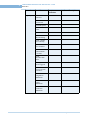
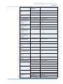
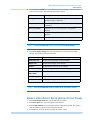
HARDWARE SPECIFICATIONS
.................................................................
The MAXPRO VMS server and client computers must meet the minimum hardware
specifications. This is necessary for proper and efficient working of the MAXPRO VMS.
There are two types of hardware configurations for the server and client namely, standard and
performance. The standard configuration uses the minimum hardware specifications. The
performance configuration uses higher hardware specifications for better performance. The
performance configuration is also recommended for compatibility with features that are going
to be provided in MAXPRO VMS in the near future.
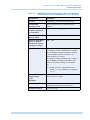
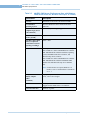
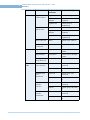
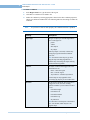
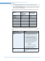
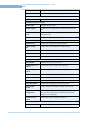
Table 2-1
MAXPRO VMS Server (Standard Spec with Windows 2008
Server R2 64 bit, Windows 2012 up to 5 Clients)
Specification Description
Processor
Single Intel® Quad Core Xeon E3 1224V3 3.2 GHz
Recommended
Operating System
Microsoft Windows® Server 2008 R2 and 2012
32&64 bit
Recommended
Computer Type (Server
or Workstation)
Server - dual power supply suggested
Recommended System
Memory (RAM)
8 GB
DVD Drive (RW (Read
Write) is required if
workstation is used for
exporting recordings)
DVD +/- RW
Disk
Two separate hard drives or two sets of RAID arrays
Disk / RAID set 1 utilizes 10K RPM SATA 150GB or
10K-15K RPM SCSI 146GB for Windows operating
system, MAXPRO VMS Server Software, and
Microsoft SQL Server software.
Disk / RAID set 2 utilizes 10K RPM SATA 150GB or
10K-15K RPM SCSI 146GB for MAXPRO VMS
database files and Microsoft SQL Server database
files.
Note: If fault tolerance is required, RAID set 1 is
RAID 1, 10 or 0+1 and RAID set 2 is RAID 10
or 0 + 1.
Multiple Monitor Card
-Display Adapter
(Video
Display Adapter with Video resolution 1024x768
pixels; 32-bit color or higher.
Resolution)
20
Serial Ports
Only required if serial device are to be connected Suggested 8 Port MOXA PCI-e serial RS232
Network Connection
1Gbit/sec or greater
MAXPRO VMS R310 Commissioning and Installation Guide
. . . . .
SETTING UP THE CLIENT AND THE SERVER COMPUTERS
Hardware Specifications
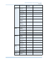
Table 2-2
MAXPRO VMS Server (Performance Spec with Windows
2008 Server R2 64 bit, Windows 2012 up to 10 Clients)
Specification Description
Processor
Single Intel® 6 Core Xeon E5 2630V2 2.6GHz
Recommended
Operating System
Microsoft Windows® Server 2008 R2 and 2012
32&64 bit
Recommended
Computer Type (Server
or Workstation)
Server - dual power supply suggested
Recommended System
Memory (RAM)
16GB
DVD Drive (RW (Read
Write) is required if
workstation is used for
exporting recordings)
DVD +/- RW
Disk
Two separate hard drives or two sets of RAID arrays
Disk / RAID set 1 utilizes 10K RPM SATA 150GB or
10K-15K RPM SCSI 146GB for Windows operating
system, MAXPRO VMS Server Software, and
Microsoft SQL Server software.
Disk / RAID set 2 utilizes 10K RPM SATA 150GB or
10K-15K RPM SCSI 146GB for MAXPRO VMS
database files and Microsoft SQL Server database
files.
Note: If fault tolerance is required, RAID set 1 is
RAID 1, 10 or 0+1 and RAID set 2 is RAID 10
or 0 + 1.
Multiple Monitor Card
-Display Adapter
(Video
Display Adapter with Video resolution 1024x768
pixels; 32-bit color or higher
Resolution)
Serial Ports
Only required if serial device are to be connected Suggested 8 Port MOXA PCI-e serial RS232
Network Connection
1Gbit/sec or greater.
MAXPRO VMS R310 Commissioning and Installation Guide
21
2
SETTING UP THE CLIENT AND THE SERVER COMPUTERS
Hardware Specifications
Table 2-3
MAXPRO VMS Server (Performance Spec with Windows
2008 Server R2 64 bit, Windows 2012 up to 25 Clients)
Specification Description
Processor
Dual Intel® 6 Core Xeon’s E5 2630V2 2.6GHz
Recommended
Operating System
Microsoft Windows® Server 2008 R2 and 2012
32&64 bit
Recommended
Computer Type (Server
or Workstation)
Server - dual power supply suggested
Recommended System
Memory (RAM)
16GB
DVD Drive (RW (Read
Write) is required if
workstation is used for
exporting recordings)
DVD +/- RW
Disk
Two separate hard drives or two sets of RAID arrays
Disk / RAID set 1 utilizes 10K RPM SATA 150GB or
10K-15K RPM SCSI 146GB for Windows operating
system, MAXPRO VMS Server Software, and
Microsoft SQL Server software.
Disk / RAID set 2 utilizes 10K RPM SATA 150GB or
10K-15K RPM SCSI 146GB for MAXPRO VMS
database files and Microsoft SQL Server database
files.
Note: If fault tolerance is required, RAID set 1 is
RAID 1, 10 or 0+1 and RAID set 2 is RAID 10
or 0 + 1.
Multiple Monitor Card
-Display Adapter
(Video
Display Adapter with Video resolution 1024x768
pixels; 32-bit color or higher
Resolution)
22
Serial Ports
Only required if serial device are to be connected Suggested 8 Port MOXA PCI-e serial RS232
Network Connection
1Gbit/sec or greater.
MAXPRO VMS R310 Commissioning and Installation Guide
. . . . .
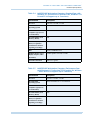
SETTING UP THE CLIENT AND THE SERVER COMPUTERS
Hardware Specifications
Table 2-4
MAXPRO VMS Workstation Computer (Standard Spec with
Windows 8.1 Professional 32-Bit and 64 bit, Windows 7 64
bit and 32 bit Supports up to 2 monitors)
Specification Description
Processor
Intel Core i7-4770K, 3.5 GHz
Recommended
Operating System
Microsoft Windows® 7 or 8.2 32&64 bit
Recommended
Computer Type (Server
or Workstation)
Workstation.
Recommended System
Memory (RAM)
8GB.
DVD Drive (RW (Read
Write) is required if
workstation is used for
exporting recordings)
DVD +/- RW.
Disk
250GB 7200RPM SATA3
Multiple Monitor Card Display Adapter (Video
NVIDIA Quadro NVS300, 512 MB
Resolution)
Network Connection
Table 2-5
1Gbit/sec or greater.
MAXPRO VMS Workstation Computer (Performance Spec
with Windows 8.1 Professional 32-Bit and 64 Bit, Windows
7 64 bit and 32 bit supports up to 4 monitors)
Specification Description
Processor
Intel Core i7-4770K, 3.5 GHz
Recommended
Operating System
Microsoft Windows® 7 or 8.2 32&64 bit
Recommended
Computer Type (Server
or Workstation)
Workstation.
Recommended System
Memory (RAM)
8 GB.
DVD Drive (RW (Read
Write) is required if
workstation is used for
exporting recordings)
DVD +/- RW
MAXPRO VMS R310 Commissioning and Installation Guide
23
2
SETTING UP THE CLIENT AND THE SERVER COMPUTERS
Hardware Specifications
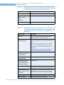
Table 2-5
MAXPRO VMS Workstation Computer (Performance Spec
with Windows 8.1 Professional 32-Bit and 64 Bit, Windows
7 64 bit and 32 bit supports up to 4 monitors)
Specification Description
Disk
250GB 7200RPM SATA3
Multiple Monitor Card
-Display Adapter
(Video
NVIDIA Quadro NVS510, 2GB
Resolution)
Network Connection
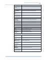
Table 2-6
1Gbit/sec or greater.
MAXPRO VMS Workstation Computer with Prowatch client
(Performance Spec with Windows 8.1 Professional 32-Bit
and 64 Bit, Windows 7 64 bit and 32 bit supports up to 2
monitors)
Specification Description
Processor
Quad Core Intel® Xeon® Processor E5620 (12M
Cache, 2.40 GHz, 5.86 GT/s Intel® QPI).
Recommended
Operating System
Microsoft Windows® 7 Professional (64-Bit and 32Bit), Microsoft Windows® 8.1 Professional 32-Bit and
64 Bit
Few of the recorders run only on specific operating
systems. Before installing the device drivers for the
recorders, please refer to the “Operating Systems”
sheet in the
MAXPROVMS_HW_SW_Compatibility_Matrix.xls
file available on the MAXPRO VMS R310 DVD.
24
Recommended
Computer Type (Server
or Workstation)
Workstation.
Recommended System
Memory (RAM)
8 GB.
DVD Drive (RW (Read
Write) is required if
workstation is used for
exporting recordings)
DVD-RW drive.
Disk
Single Disk or RAID 0 or 0+1 10K SATA 80GB or
10K to 15K SAS 73GB: Windows Operating System.
Multiple Monitor Card
-Display Adapter (Video
Resolution)
1 x 256MB PCIe x16 NVIDIA Quadro NVS 285, Dual
DVI or Dual VGA or DVI+VGA. This is for a two
monitor setup with each monitor requiring 128 MB.
Network Connection
1Gbit/sec or greater.
Video Resolution
1024x768 pixels; 24 bit color or higher.
MAXPRO VMS R310 Commissioning and Installation Guide
. . . . .
SETTING UP THE CLIENT AND THE SERVER COMPUTERS
Configuring the Monitor Display Properties
CONFIGURING THE MONITOR DISPLAY
PROPERTIES
.................................................................
The recommended display settings for the monitor are dialog box resolution of 1024 x 768
pixels and color quality of 65K colors non-interlaced. The display settings can be configured
from the Windows control panel or from the Windows desktop through the context menu.
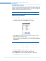
To configure the display settings from the context menu in the Windows desktop
1.
Right-click the Windows desktop to display the context-menu.
2.
Click Properties. The Display Properties dialog box appears.
3.
Click the Settings tab.
4.
Select the dialog box resolution and color quality.
5.
Click Apply to save the settings.
6.
Click OK to close the dialog box.
To configure the display settings from the Windows control panel
1.
Go to Windows control panel.
Note:
To open the control panel, click Start > Settings > Control Panel.
2.
Double-click the Display icon.The Display Properties dialog box appears.
3.
Click the Settings tab.
4.
Select the dialog box resolution and color quality.
5.
Click Apply to save the settings.
6.
Click OK to close the dialog box.
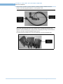
ABOUT SERIAL EXPANDER
.................................................................
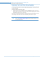
The serial expander cable is used for increasing the number of serial ports in the computer.
One end of the serial expander cable connects to a serial port in the computer. The other end
of the serial expander cable consists of eight serial ports to which you can connect serial
devices. For example, you can install the serial expander in the server to connect serial
MAXPRO VMS R310 Commissioning and Installation Guide
25
2
SETTING UP THE CLIENT AND THE SERVER COMPUTERS
About Serial Expander
devices such as switchers, joystick controllers (Ultrak keyboard), and PITs used at the
location. The following figure illustrates a serial expander cable.
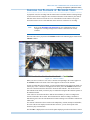
Each of the eight serial ports in the serial expander cable is marked with a number. This
number is used for identifying the serial port while configuring the settings such as baud rate,
data bits, and others using the MAXPRO VMS software.
The following figure illustrates the serial port numbering in the serial expander cable.
26
MAXPRO VMS R310 Commissioning and Installation Guide
. . . . .
SETTING UP THE CLIENT AND THE SERVER COMPUTERS
Enabling Windows .NET 3.5
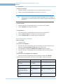
ENABLING WINDOWS .NET 3.5
.................................................................
This section describes the procedure to enable .NET 3.5 on Windows 8 and Server 2012
machine with/without internet connection.
Note:
This section is not applicable for Windows 7 and Server 2008 machines to enable
. NET 3.5.
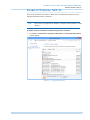
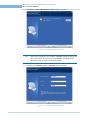
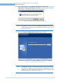
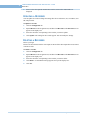
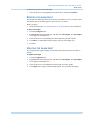
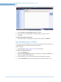
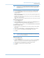
To enable .NET 3.5 on Windows 8 machine using internet connection
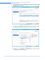
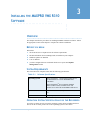
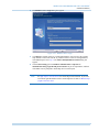
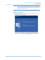
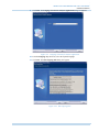
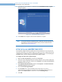
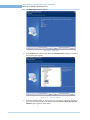
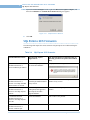
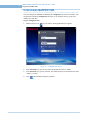
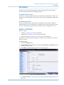
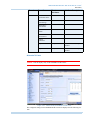
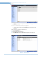
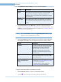
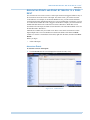
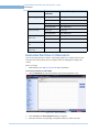
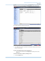
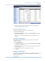
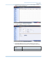
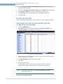
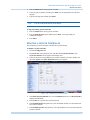
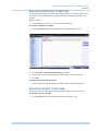
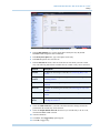
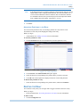
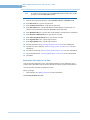
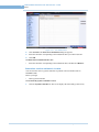
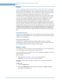
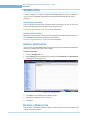
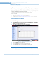
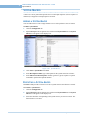
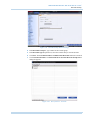
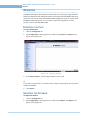
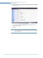
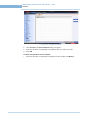
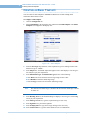
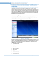
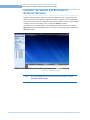
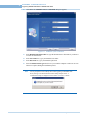
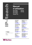
1.
Click Start > Control Panel > Programs and Features. The Programs and Features
window appears.
Figure 1-1
MAXPRO VMS R310 Commissioning and Installation Guide
Program and Features
27
2
SETTING UP THE CLIENT AND THE SERVER COMPUTERS
Enabling Windows .NET 3.5
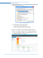
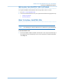
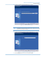
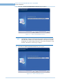
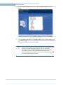
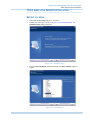
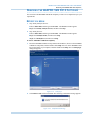
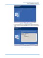
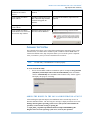
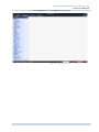
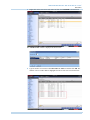
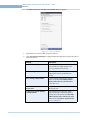
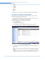
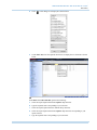
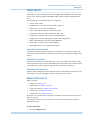
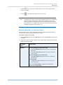
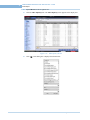
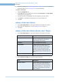
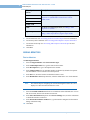
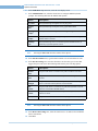
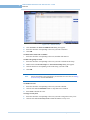
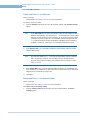
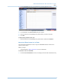
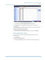
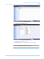
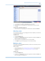
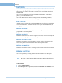
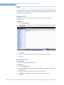
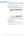
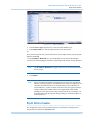
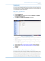
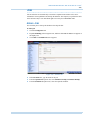
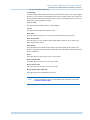
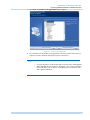
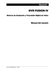
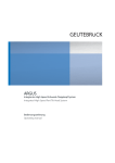
2.
Under Control Panel Home pane, click Turn Windows features on or off link. The
Windows Features dialog box appears.
Figure 1-2
3.
Windows Features
Select the following check boxes and then click OK.
•
•
•
.Net Framework 3.5 (includes .Net2.0 and 3.0)
Windows Communication Foundation HTTP Activation
Windows Communication Foundation Non-HTTP Activation
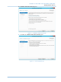
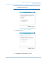
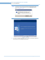
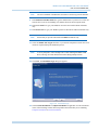
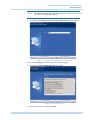
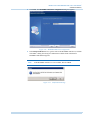
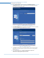
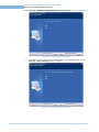
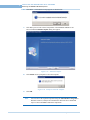
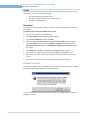
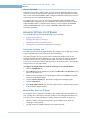
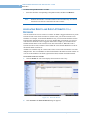
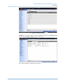
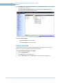
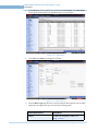
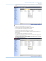
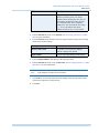
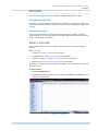
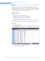
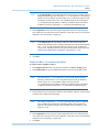
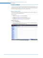
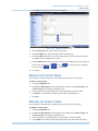
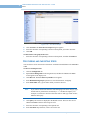
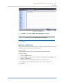
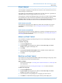
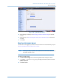
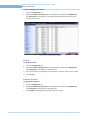
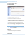
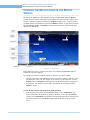
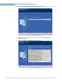
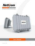
To enable .NET 3.5 on Windows Server 2012 machine using internet connection
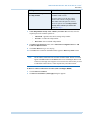
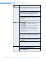
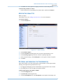
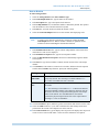
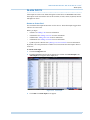
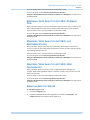
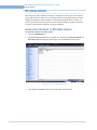
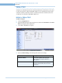
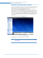
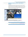
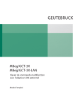
1.
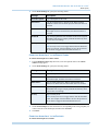
Navigate to Server Manager -> Manage and then click Add Roles and features link.
Or
Navigate to Server Manager -> Dashboard -> Configure this local server and then
click Add Roles and features link as shown below.
Figure 1-3
28
Server Manager Window
MAXPRO VMS R310 Commissioning and Installation Guide
. . . . .
SETTING UP THE CLIENT AND THE SERVER COMPUTERS
Enabling Windows .NET 3.5
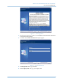
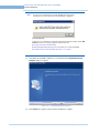
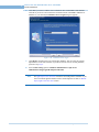
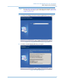
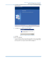
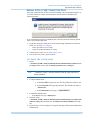
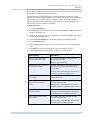
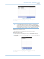
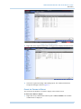
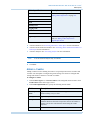
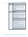
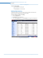
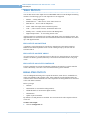
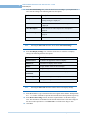
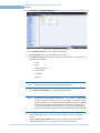
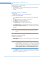
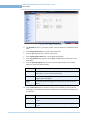
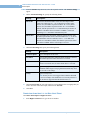
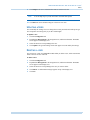
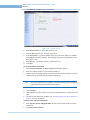
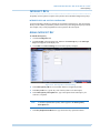
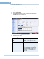
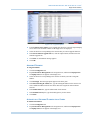
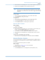
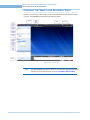
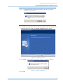
The Add Roles and Features Wizard appears.
Figure 1-4
2.
Add Roles and Features Wizard
Click Next. The Add Role and Features Wizard appears.
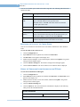
Figure 1-5
MAXPRO VMS R310 Commissioning and Installation Guide
Select Installation type
29
2
SETTING UP THE CLIENT AND THE SERVER COMPUTERS
Enabling Windows .NET 3.5
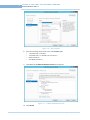
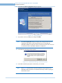
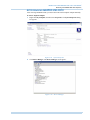
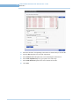
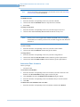
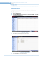
3.
Click Role-based or feature- based installation option and then click Next. The Select
Destination Server screen appears.
Figure 1-6
4.
Select destination server
Click Select a server from the server pool option and then select the current machine
name listed under Server Pool. Click Next. Select server roles screen appears.
Figure 1-7
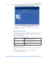
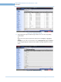
5.
30
Select Server Roles
Under Roles, select the Application server (Installed) check box and then click Next.
The Add Roles and Features Wizard appears
MAXPRO VMS R310 Commissioning and Installation Guide
. . . . .
SETTING UP THE CLIENT AND THE SERVER COMPUTERS
Enabling Windows .NET 3.5
Note:
The Add Roles and Features Wizard displayed differs on the HTTP Activation
and Non-HTTP Activation features.
Figure 1-8
6.
Click Add Features button.
Figure 1-9
7.
HTTP Activation
Non-HTTP Activation
Click Add Features. The Select Features screen appears.
MAXPRO VMS R310 Commissioning and Installation Guide
31
2
SETTING UP THE CLIENT AND THE SERVER COMPUTERS
Enabling Windows .NET 3.5
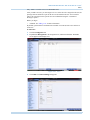
Figure 1-10
8.
Select the following feature check boxes in the Features pane:
•
•
•
•
9.
Select Features
.Net Framework 3.5 features
.Net Framework 3.5 ( includes .Net 2.0 and 3.0 )
HTTP Activation
Non-HTTP Activation
Click Next. The Confirm installation selection screen appears.
Figure 1-11
Confirm Installation Selection
10. Click Install.
32
MAXPRO VMS R310 Commissioning and Installation Guide
. . . . .
SETTING UP THE CLIENT AND THE SERVER COMPUTERS
Enabling Windows .NET 3.5
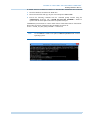
To enable .NET 3.5 on Windows 8 and Server 2012 machine without internet connection
1.
Insert the Windows OS DVD in the DVD drive.
2.
Browse the Sxs folder and copy the path. For Example: E:\ Sources\SxS.
3.
Execute the following command from the command prompt window using the
Administrative privileges. The <<PATH_TO_WIN_SXS_FOLDER>> should be
replaced with the actual path of Sxs folder as explained in step 2.
%WINDIR%\system32\dism.exe /online /enable-feature /featurename:NetFX3 /featurename:
WCF-HTTP-Activation /featurename:WCF-NonHTTP-Activation /all
/Source:<<PATH_TO_WIN_SXS_FOLDER>> /LimitAccess
Note:
Use the cmd.exe available in the path C:\windows\system32 folder on 64 bit
Operating System.
MAXPRO VMS R310 Commissioning and Installation Guide
33
2
SETTING UP THE CLIENT AND THE SERVER COMPUTERS
Enabling Windows .NET 3.5
This page is intentionally left blank
34
MAXPRO VMS R310 Commissioning and Installation Guide
3
INSTALLING THE MAXPRO VMS R310
SOFTWARE
.....
...................................
OVERVIEW
.................................................................
This chapter describes the procedures for installing MAXPRO VMS R310 software. Follow
the appropriate section in this chapter to complete the software installation.
BEFORE YOU BEGIN
Ensure that:
1.
the client and server computers meet the software requirements.
2.
Internet Information Services Manager (IIS) is installed on your computer.
3.
Windows Updates are disabled.
4.
UAC is disabled.
5.
you have configured the user credentials which never expires in Computer
Management window.
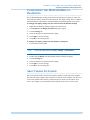
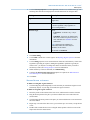
SYSTEM REQUIREMENTS
The client and server computers must meet the following specifications.
Table 2-1
Software Specifications
Operating System
Microsoft Windows® 7 Professional (64-Bit and 32Bit) and Windows 8.1 OS for MAXPRO VMS
Workstation.
Microsoft Windows® Server 2008 R2 Standard
Edition (64 Bit Version) on 64 Bit Server and
Windows server 2012 OS for MAXPRO VMS Server.
Antivirus
McAfee® VirusScan 8.8, or Symantic® Antivirus
V10.
Monitor Resolution
1024x768 pixels, 65K colors non-interlaced.
OPERATION SYSTEM SPECIFICATIONS FOR THE RECORDERS
Few of the recorders run only on specific operating systems. Before installing the device
drivers for the recorders, please refer to the “Operating Systems” sheet in the
MAXPRO VMS R310 Commissioning and Installation Guide
37
3
INSTALLING THE MAXPRO VMS R310 SOFTWARE
Overview
MAXPROVMS_HW_SW_Compatibility_Matrix.xls file available on the MAXPRO VMS
R310 DVD.
38
MAXPRO VMS R310 Commissioning and Installation Guide
. . . . .
INSTALLING THE MAXPRO VMS R310 SOFTWARE
Installing the MAXPRO VMS Software
INSTALLING THE MAXPRO VMS SOFTWARE
.................................................................
To complete MAXPRO VMS installation follow the procedures in these sections.
1.
First, How to Install MAXPRO VMS.
2.
Choose the installation that best suits your requirements and follow the appropriate steps.
•
•
Complete Installation
Custom Installation
HOW TO INSTALL MAXPRO VMS
.................................................................
Note:
The installing user should be administrator or domain/work group administrator
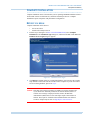
To install MAXPRO VMS
1.
Insert the MAXPRO VMS R310 DVD in the DVD drive. The setup runs automatically. If
the setup does not run automatically, browse to the setup folder on the DVD and doubleclick Setup. exe.
MAXPRO VMS R310 Commissioning and Installation Guide
39
3
INSTALLING THE MAXPRO VMS R310 SOFTWARE
How to Install MAXPRO VMS
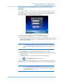
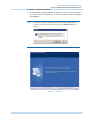
Note
A confirmation message is displayed to disable the Automatic Windows updates
as shown below. Click Yes to disable and proceed. The Welcome dialog box
appears. See Windows Updates.
Figure 3-1
2.
40
Welcome
Click Next. The License Agreement dialog box appears. The dialog box displays the
license agreement for the MAXPRO VMS software.
MAXPRO VMS R310 Commissioning and Installation Guide
. . . . .
INSTALLING THE MAXPRO VMS R310 SOFTWARE
How to Install MAXPRO VMS
Figure 3-2
License Agreement
3.
Read the license agreement, and then click I accept the terms of the license agreement
to accept the license agreement.
4.
Click Next. The Customer Information dialog box appears.
Figure 3-3
Customer Information
5.
In the Registered To box, type your name.
6.
In the Company Name box, type your company name.
MAXPRO VMS R310 Commissioning and Installation Guide
41
3
INSTALLING THE MAXPRO VMS R310 SOFTWARE
How to Install MAXPRO VMS
7.
Click Next. The Choose Destination Location dialog box appears.
Figure 3-4
Note:
8.
Honeywell recommends you to install the MAXPRO VMS R310 software in C
drive. By default C drive is selected. Click Change to change the default
destination folder, and then select the path to install.
Click Next. The Validation of User Credentials dialog box appears.
Figure 3-5
42
Choose Destination Location
Validation of User Credentials
MAXPRO VMS R310 Commissioning and Installation Guide
. . . . .
INSTALLING THE MAXPRO VMS R310 SOFTWARE
How to Install MAXPRO VMS
Note:
9.
The user credentials of theWindows user that was used to log onto the machine
In the Domain Name/Host Name list, type the domain name if you know it or select one
from the list. If you are not installing on a domain choose the local computer name.
10. In the User Name box, type your Windows user name. Provide the admin credentials
only.
11. In the Password box, type your Windows password. Provide the admin credentials only.
Note:
Ensure that you provide and install with Admin credentials only.
12. Select the Enable Auto Logon check box if you want the computer to reboot on its own
whenever required, during the installation process.
Note:
You are prompted to reboot multiple times while installing MAXPRO VMS
R310, auto log on avoids manual intervention during multiple reboots.
13. Click Next. The Installation Type dialog box appears.
Figure 3-6
Installation Type
14. Select Custom Installation or Complete Installation as applicable. Use the instructions
in one of the following sections that corresponds to the feature that you are installing,
Complete Installation or Custom Installation.
MAXPRO VMS R310 Commissioning and Installation Guide
43
3
INSTALLING THE MAXPRO VMS R310 SOFTWARE
How to Install MAXPRO VMS
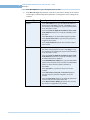
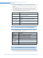
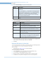
Table 2-2
Select Features to Install
Complete Installation
Installs MAXPRO VMS Server, MAXPRO VMS
Client, MAXPRO VMS Scheduler, MAXPRO VMS
Trinity Framework, Device drivers, Adapters and
Analytics Sever and Client. See Complete
Installation.
Custom Installation
Helps you to choose between MAXPRO VMS Server,
MAXPRO VMS Client and Analytics Sever and
Client. See Custom Installation.
Note: Choosing the “Custom Installation” option can
save the installation time by eliminating the
installation of any unnecessary modules.
44
MAXPRO VMS R310 Commissioning and Installation Guide
. . . . .
INSTALLING THE MAXPRO VMS R310 SOFTWARE
Complete Installation
COMPLETE INSTALLATION
.................................................................
Complete installation can be selected when you are operating MAXPRO VMS R310 from a
location that consists of all the Drivers, Switchers and Analytics Servers. Complete
installation requires computers with performance configuration.
BEFORE YOU BEGIN
Complete installation can be done to:
1.
• Server and Client.
• Install Video Analytics Server
Perform steps 1 through 13 of How to Install MAXPRO VMS, select Complete
Installation in the Installation Type dialog box, and then click Next. Click Next. The
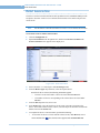
Database Server Login dialog box appears.
Figure 3-7
2.
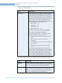
Database Server Login
Click Browse, and then select any existing SQL database. You can select the existing
SQL database on the same network or from a remote computer. If you do not want to
select an existing database, proceed to step 4.
Caution: If the SQL Server Express instance is available on a remote computer and
if you do not have sufficient permissions to fetch the instance, then as a
result an error message is displayed. In this scenario, the Database
Administrator (DBA) must execute some SQL scripts so that instance is
fetched. The scripts are available on the installation DVD. For different
scenarios on SQL Express 2012 see SQL Express 2012 Scenarios.
MAXPRO VMS R310 Commissioning and Installation Guide
45
3
INSTALLING THE MAXPRO VMS R310 SOFTWARE
Complete Installation
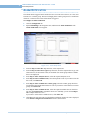
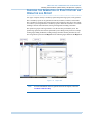
3.
Select Connect using option as Windows authentication or SQL Server
authentication using Login ID and password below as per the requirement, and then
click Next. You are prompted to install SQL Server 2012 Express.
Figure 3-8
Note:
4.
Prompt to install SQL Server 2012 Express
See SQL Express 2012 Scenarios for various SQL 2012 Scenarios. If you enter an
invalid Login ID and Password to connect SQL Server then see Manual Steps if
SQL Connection Fails.
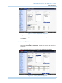
Click Yes. The Choose TrinityDatabase location dialog box appears.
Figure 3-9
Note:
46
Choose TrinityDatabase Location
Click Browse to change the default destination folder, and then select the folder
where the Trinity database server must be installed. It is best practice to Install
the Database on a seperate Mirrored hard drive. This ensures the database is still
available if the OS drive is failed or get corrupted.
MAXPRO VMS R310 Commissioning and Installation Guide
. . . . .
INSTALLING THE MAXPRO VMS R310 SOFTWARE
Complete Installation
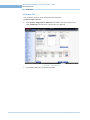
5.
Click Next. The Choose Cache file location dialog box appears.
Figure 3-10
Note:
6.
Click Browse to change the default destination folder, and then select the folder
where the cache files must be installed.
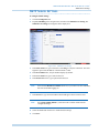
Click Next. The Language selection for analytics application dialog box appears.
Figure 3-11
7.
Choose Cache file location
Language selection for analytics application
From the Language drop-down list, select the required language.
MAXPRO VMS R310 Commissioning and Installation Guide
47
3
INSTALLING THE MAXPRO VMS R310 SOFTWARE
Complete Installation
8.
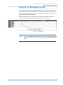
Click Next. The Start Copying Files dialog box appears.
Figure 3-12
9.
Start Copying Files
If you want to review or change any settings click Back.
Note:
The Start Copying Files dialog box displays the total approximate time for
installing the prerequisites and total approximate time for installing the
MAXPRO VMS R310 components. Please note that prerequisites take more time
for installation than the MAXPRO VMS R310 components.
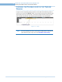
10. Click Next. The following message appears.
Figure 3-13
Confirmation Message to install Prerequisites
11. Click Yes to install the prerequisites automatically, else click No.
Note:
48
From step 12 onwards till the end of the installation, the prerequisites and
MAXPRO VMS components are installed automatically without requiring any
manual intervention.
MAXPRO VMS R310 Commissioning and Installation Guide
. . . . .
INSTALLING THE MAXPRO VMS R310 SOFTWARE
Custom Installation
12. After all the prerequisites and MAXPRO VMS R310 components are successfully
installed, the InstallShield Wizard Complete dialog box appears.
Figure 3-14
Install Shield Wizard Complete
13. Click Finish. Your computer reboots. The installation is complete after the reboot
operation.
CUSTOM INSTALLATION
.................................................................
Custom installation gives you an option to install the server and the client. You can choose to
install various device drivers. The following table lists the type of installation you can do
using the custom installation option.
Table 2-3
Select features to install
Server
MAXPRO VMS server and device drivers are
installed. See Server Installation.
Client
MAXPRO VMS client and MAXPRO VMS
Framework are installed. See Client Installation.
Honeywell Video Analytics
(HVA)
Video Analytics is installed, Video Analytics Server
Installation
SERVER INSTALLATION
Server installation involves installing MAXPRO VMS server, device drivers, and redundant
server.
1.
Perform steps 1 through 13 in the section How to Install MAXPRO VMS. The
Installation Type dialog box appears.
MAXPRO VMS R310 Commissioning and Installation Guide
49
3
INSTALLING THE MAXPRO VMS R310 SOFTWARE
Custom Installation
2.
Select Custom Installation, and then click Next. The Select Features dialog box
appears.
Figure 3-15
Note:
3.
Beta version drivers are supported but not tested.
Select MAXPRO VMS Server, and then click Next.
Note:
50
Select Features
You can add the device drivers and other features at a later stage if required. At
any point if the R310 installation fails to install the selected component, you can
clean the system using the Uninstall Utility and then reinstall the R310 software.
See Cleaning the System.
MAXPRO VMS R310 Commissioning and Installation Guide
. . . . .
INSTALLING THE MAXPRO VMS R310 SOFTWARE
Custom Installation
4.
The Database Server Login dialog box appears.
Figure 3-16
Database Server Login
5.
Click Browse, and then select any existing SQL database. You can select the existing
SQL database on the same network. If you do not want to select an existing database,
click Next and proceed to step 7. The Choose TrinityDatabase location dialog box
appears.
6.
Select Connect using option as Windows authentication or SQL Server
authentication using Login ID and password below as per the requirement, and then
click Next. You are prompted to install SQL Server 2012 Express.
Note:
See SQL Express 2012 Scenarios for various SQL 2012 Scenarios. If you enter
an invalid Login ID and Password to connect SQL Server then see Manual Steps
if SQL Connection Fails.
MAXPRO VMS R310 Commissioning and Installation Guide
51
3
INSTALLING THE MAXPRO VMS R310 SOFTWARE
Custom Installation
7.
Click Yes. The Choose TrinityDatabase location dialog box appears.
Figure 3-17 Choose TrinityDatabase location
Note:
8.
Click Browse to change the default destination folder, and then select the folder
where the Trinity database server must be installed. It is best practice to Install
the Database on a seperate Mirrored hard drive. This ensures the database is still
available if the OS drive is failed or get corrupted.
Click Next. The Choose Cache file location dialog box appears.
Figure 3-18
52
Choose Cache file location
MAXPRO VMS R310 Commissioning and Installation Guide
. . . . .
INSTALLING THE MAXPRO VMS R310 SOFTWARE
Custom Installation
Note:
9.
Click Browse to change the default destination folder, and then select the folder
where the cache files must be installed.
Click Next. The Language selection for analytics application dialog box appears.
Figure 3-19
Language selection for analytics application
10. From the Language drop-down list, select the required language.
11. Click Next. The Start Copying Files dialog box appears.
Figure 3-20
Start Copying Files
12. If you want to make any changes click Back.
MAXPRO VMS R310 Commissioning and Installation Guide
53
3
INSTALLING THE MAXPRO VMS R310 SOFTWARE
Custom Installation
Note
In some PCs the installation fails to enable MSMQ (Message Queuing)
automatically. In such scenarios the following message is displayed.
To resolve this issue
1. After the server installation is completed, download and install the windows update KB
2749655 (based on your Operating System) from the below site.
http://support.microsoft.com/kb/2749655
2. Refer and perform the instruction given in the below site to enable the MSMQ.
http://msdn.microsoft.com/en-us/library/aa967729(v=vs.110).aspx
13. Click Next. The MAXPRO VMS Server is installed and the InstallShield Wizard
Complete dialog box appears.
Figure 3-21
Install Shield Wizard Complete
14. Click Finish. The computer restarts and the installation is complete.
54
MAXPRO VMS R310 Commissioning and Installation Guide
. . . . .
INSTALLING THE MAXPRO VMS R310 SOFTWARE
Custom Installation
Note:
At any point if the R310 installation fails to install the selected components, then
you must clean the system using the Uninstall Utility and reinstall the R310
software. See Cleaning the System.
CLIENT INSTALLATION
1.
Perform steps 1 through 13 in the section How to Install MAXPRO VMS. The
Installation Type dialog box appears.
Figure 3-22
MAXPRO VMS R310 Commissioning and Installation Guide
Installation Type
55
3
INSTALLING THE MAXPRO VMS R310 SOFTWARE
Custom Installation
2.
Select Custom Installation, and then click Next. The Select Features dialog box
appears.
Figure 3-23
3.
Select MAXPRO VMS Client. The MAXPRO VMS Framework, Device Drivers, and
the Analytics Engine are selected automatically. Clear the check boxes corresponding to
the device drivers that you do not want to install.
Note:
56
Select Features
If you are installing the drivers in a client PC and later if you upgrade the Client
PC to Server PC then the respective driver scripts does not load the
configurations in the MAXPRO VMS R310 Viewer. User should run the
corresponding script (For example: HRDPUnInstallationScript.sql,
PelcoInstallationScript.sql) manually to load the configurations from the Tools
(Tools\SQLScripts\DVRScripts) folder.
MAXPRO VMS R310 Commissioning and Installation Guide
. . . . .
INSTALLING THE MAXPRO VMS R310 SOFTWARE
Custom Installation
4.
Click Next. The MAXPRO VMS Client configuration dialog box appears.
Figure 3-24
5.
MAXPRO VMS Client Configuration
In the MaxproVMS Server box, type the name of the MAXPRO VMS Server, and then
click Next. A dialog box asking for confirmation to add the client workstation to
MAXPRO VMS database appears.
Note:
If the MAXPRO VMS Server is not available, then click Next.
Figure 3-25
MAXPRO VMS R310 Commissioning and Installation Guide
Confirmation Message
57
3
INSTALLING THE MAXPRO VMS R310 SOFTWARE
Custom Installation
6.
Click Yes if you want to add the client workstation name in MAXPRO VMS database.
Click No if you do not want to add client workstation name in MAXPRO VMS Server
Database. If you click Yes, the Database Server Login dialog box appears.
Figure 3-26
7.
Click Browse, and then select any existing SQL database. You can select the existing
SQL database on the same network. If you do not want to select an existing database,
proceed to step step 9.
8.
Select Connect using option as Windows authentication or SQL Server
authentication using Login ID and password below.
Note:
58
Database Server Login
See SQL Express 2012 Scenarios section for various SQL 2012 Scenarios. If you
enter an invalid Login ID and Password to connect SQL Server then see Manual
Steps if SQL Connection Fails section.
MAXPRO VMS R310 Commissioning and Installation Guide
. . . . .
INSTALLING THE MAXPRO VMS R310 SOFTWARE
Custom Installation
9.
Click Next. The Language selection for analytics application dialog box appears.
Figure 3-27
Language selection for analytics application
10. From the Language drop-down list, select the required language.
11. Click Next. The Start Copying Files dialog box appears.
Figure 3-28
MAXPRO VMS R310 Commissioning and Installation Guide
Start Copying Files
59
3
INSTALLING THE MAXPRO VMS R310 SOFTWARE
Custom Installation
12. Click Next. The MAXPRO VMS client is installed and the InstallShield Wizard
Complete dialog box appears.
Figure 3-29
Install Shield Wizard Complete
13. Click Finish. The computer restarts and the installation is complete.
Note:
At any point if the R310 installation fails to install the selected component, you
can clean the system using the Uninstall Utility and then reinstall the R310
software. See Cleaning the System.
R U N N I N G T H E D R I V ER S C R I P T S M A N U A L L Y
After installing the drivers in Client PC for example ( NVR Driver, Digital Sentry, HRDP,
HRXD, VMS in VMS, Milestone, LG, Panasonic, EXACQ, GeViScope, Pelco Endura) If the
Client PC is upgraded to Server PC then the respective driver scripts does not load the
configurations in the MAXPRO VMS R310 Viewer. User should run the corresponding script
manually for example (HRDPUnInstallationScript.sql, PelcoInstallationScript.sql) from the
Tools (Tools\SQLScripts\DVRScripts) folder.
60
MAXPRO VMS R310 Commissioning and Installation Guide
. . . . .
INSTALLING THE MAXPRO VMS R310 SOFTWARE
Video Analytics Server Installation
VIDEO ANALYTICS SERVER INSTALLATION
.................................................................
BEFORE YOU BEGIN
•
Ensure that the MAXPRO VMS server is installed.
1.
Perform steps 1 through 13 in the section How to Install MAXPRO VMS. The
Installation Type dialog box appears.
Figure 3-30
2.
Installation Type
Select Custom Installation, and then click Next. The Select Features dialog box
appears.
Figure 3-31
MAXPRO VMS R310 Commissioning and Installation Guide
Select Features
61
3
INSTALLING THE MAXPRO VMS R310 SOFTWARE
Video Analytics Server Installation
3.
Select Analytics Engine, and then click Next. The MAXPRO VMS Client
configuration dialog box appears. Clear the check boxes corresponding to the device
drivers which you do not wish to install.
Figure 3-32
4.
MAXPRO VMS Client Configuration
In the MaxproVMS Server box, type the name of the MAXPRO VMS Server, and then
click Next. The Database Server Login dialog box appears.
Figure 3-33
62
Database Server Login
5.
Click Browse, and then select any existing SQL database. You can select the existing
SQL database on the same network. If you do not want to select an existing database,
proceed to step step 7.
6.
Select Connect using option as Windows authentication or SQL Server
authentication using Login ID and password below.
MAXPRO VMS R310 Commissioning and Installation Guide
. . . . .
INSTALLING THE MAXPRO VMS R310 SOFTWARE
Video Analytics Server Installation
Note:
7.
See SQL Express 2012 Scenarios for various SQL 2012 Scenarios. If you enter
an invalid Login ID and Password to connect SQL Server then see Manual Steps
if SQL Connection Fails.
Click Next. The Language selection for analytics application dialog box appears.
Figure 3-34
8.
Language Selection for Analytics Application
Click Next. The Start Copying Files dialog box appears.
Figure 3-35
MAXPRO VMS R310 Commissioning and Installation Guide
Start Copying Files
63
3
INSTALLING THE MAXPRO VMS R310 SOFTWARE
Video Analytics Server Installation
9.
Click Next. The video Analytics is installed and the InstallShield Wizard Complete
dialog box appears.
Figure 3-36
Install Shield Wizard Complete
10. Click Finish. Your computer restarts and the installation is complete.
Note:
At any point if the R310 installation fails to install the selected component, you
can clean the system using the Uninstall Utility and then reinstall the R310
software. See Cleaning the System.
AFTER INSTALLING MAXPRO VMS R310
The Loopback Adapters enables to stabilize the network connection in case of any network
disconnect momentarily. The loopback adapters are required in a site to stabilize the network
communication. In addition, these are recommended for MVMS servers. After installing the
MAXPRO VMS, you must configure the Microsoft Loopback Adapter.
To configure the Microsoft Loopback Adapter
64
1.
Right-click My Network Places, and then select Properties.
2.
Locate the LAN or High-Speed Internet connection that has a device name of Microsoft
Loopback Adapter, right-click, and then select Properties. The Local Area Connection
Properties dialog box appears.
3.
Select Internet Protocol (TCP/IP), and then click Properties. The Internet Protocol
(TCP/IP) Properties dialog box appears.
4.
Select Use the following IP address.
5.
In the IP address box, type the IP address between the range of 10.0.0.0 to
10.255.255.255 or 192.168.0.0 to 192.168.255.255. The subnet mask 255.255.255.0
appears in the Subnet mask box. Do not set a value for Default gateway
6.
Click OK.
MAXPRO VMS R310 Commissioning and Installation Guide
. . . . .
INSTALLING THE MAXPRO VMS R310 SOFTWARE
Removing the MAXPRO VMS R310 Software
REMOVING THE MAXPRO VMS R310 SOFTWARE
.................................................................
You can remove the MAXPRO VMS R310 completely or some of it’s components as per your
requirements.
BEFORE YOU BEGIN
1.
Stop Trinity Analytics Services.
a.Choose Start>Run, and then type services.msc. The Services window appears.
b.Right-click Trinity Analytics Service, and then select Stop.
2.
Stop Trinity Services.
a.Choose Start>Run, and then type services.msc. The Services window appears.
b.Right-click TrinityContoller, and then select Stop.
c.Right-click TrinityServer, and then select Stop.
To remove MAXPRO VMS R310 completely
1.
Insert the MAXPRO VMS R310 setup DVD in the DVD drive, browse to the MAXPRO
VMS R310 setup folder, and then double-click Setup. exe or Go to the MAXPRO VMS
R310 setup folder in your computer, and then double-click Setup. exe. The Setup Type
dialog box appears.
Figure 3-37
2.
Setup Type
Select Remove All, and then click Next. The following confirmation message appears.
Figure 3-38
MAXPRO VMS R310 Commissioning and Installation Guide
Confirmation Message
65
3
INSTALLING THE MAXPRO VMS R310 SOFTWARE
Removing the MAXPRO VMS R310 Software
3.
Click Yes. The Restoring Trinity Database dialog box appears.
Figure 3-39
4.
Click Yes to retain the Trinity database and click No to delete the Trinity database. The
Restoring Analytics Database dialog box appears.
Figure 3-40
66
Restoring Trinity Database
Restoring Analytics Database
MAXPRO VMS R310 Commissioning and Installation Guide
. . . . .
INSTALLING THE MAXPRO VMS R310 SOFTWARE
Removing the MAXPRO VMS R310 Software
5.
Click Next. The MAXPRO VMS R310 is removed completely and Uninstall Complete
dialog box appears.
Figure 3-41
6.
Click Finish. You are prompted to reboot the computer.
Figure 3-42
7.
Uninstall Complete
Prompt to remove few components
Click OK.
To remove few components
1.
Insert the MAXPRO VMS R310 setup DVD in the DVD drive, browse to the MAXPRO
VMS R310 setup folder, and then double-click Setup. exe or go to the MAXPRO VMS
R310 setup folder in your computer, and then double-click Setup. exe.
MAXPRO VMS R310 Commissioning and Installation Guide
67
3
INSTALLING THE MAXPRO VMS R310 SOFTWARE
Removing the MAXPRO VMS R310 Software
2.
The Setup Type dialog box appears.
Figure 3-43
3.
Select Remove Few, and then click Next. The Select the features dialog box similar to
the following figure appears.
Figure 3-44
4.
68
Setup Type
Select the Features
Select the components that you wish to remove by selecting the respective check boxes.
If you select the Analytics driver to uninstall and click Next then Restoring Analytics
Database figure appears as shown below.
MAXPRO VMS R310 Commissioning and Installation Guide
. . . . .
INSTALLING THE MAXPRO VMS R310 SOFTWARE
Removing the MAXPRO VMS R310 Software
Figure 3-45
5.
Restoring Analytics Database
Click the required option to retain the Analytics database residing in Analytics Engine,
and then Click Next. The Start Copying Files dialog box similar to the following figure
appears.
Figure 3-46
MAXPRO VMS R310 Commissioning and Installation Guide
Start Copying Files
69
3
INSTALLING THE MAXPRO VMS R310 SOFTWARE
Removing the MAXPRO VMS R310 Software
6.
Click Next. A confirmation message appears as shown below.
7.
Click Yes to proceed. The selected components of the MAXPRO VMS R310 are
removed and the Uninstall Complete dialog box appears.
Figure 3-47
8.
Click Finish. You are prompted to reboot the computer.
Figure 3-48
9.
Prompt to reboot the computer
Click OK.
Note:
70
Uninstall Complete
You can remove the required component using the Add or Remove Programs in
Windows. However, Honeywell recommends to follow the above mentioned
steps to remove MAXPRO VMS R310 components.
MAXPRO VMS R310 Commissioning and Installation Guide
. . . . .
INSTALLING THE MAXPRO VMS R310 SOFTWARE
Removing the MAXPRO VMS R310 Software
AFTER REMOVING MAXPRO VMS R310
After removing MAXPRO VMS, you must remove Microsoft Loopback Adapter manually.
To remove loopback adapter
1.
Right-click My Computer, and then select Properties. The System Properties dialog
box appears.
Figure 3-49
2.
System Properties
Click Device Manager. The Device Manager screen appears.
Figure 3-50
MAXPRO VMS R310 Commissioning and Installation Guide
Device Manager
71
3
INSTALLING THE MAXPRO VMS R310 SOFTWARE
SQL Express 2012 Scenarios
3.
Expand the Network Adapter branch, right-click Microsoft Loopback Adapter, and
then select Uninstall. The Confirm Device Removal dialog box appears.
Figure 3-51
4.
Confirm Device Removal
Click OK.
SQL EXPRESS 2012 SCENARIOS
.................................................................
The following table depicts the various scenarios of SQL Express 2012 while installing the
VMS R310.
Table 2-4
SQL Express 2012 Scenarios
R310 Installation Scenarios
SQL 2012 SP1 Express
Supported OS
SQL 2012 SP1 Express Unsupported OS ( If
operating system service pack is not installed
then)
If you choose for Fresh
installation and Server is
Selected without SQL instance.
Installs the SQL Express 2012
SP1 and Create Database.
It displays an error message as shown below.
If you choose for Fresh
installation and Server is
selected + local SQL Standard
Edition instance is selected.
Creates the Database in the
selected SQL Standard instance
of any version.
Create Database in the selected SQL Standard
instance of any version.
If you choose for Fresh
installation and Server is
Selected + local SQL Express
2008 R2.
Installs the SQL 2008 R2 SP1
(If Required) and Upgrade to
SQL Express 2012 SP1 +
Upgrade Database.
Create Database in SQL Express 2008 R2
instance.
If you choose for Fresh
installation and Server is
Selected + local SQL Express
2012 SP1.
Creates the Database.
This scenario is not possible.
If you choose for Fresh
installation and Server is
selected + Remote SQL.
Creates the Database.
Create Database.
72
MAXPRO VMS R310 Commissioning and Installation Guide
. . . . .
INSTALLING THE MAXPRO VMS R310 SOFTWARE
SQL Express 2012 Scenarios
If you choose for Fresh
installation and Client is
selected.
Client components will be
installed.
Client components will be installed.
If you Upgrade from R300
Server to R310.
Upgrades to SQL Express 2012
SP1, if R300 has SQL 2008 R2
available and upgrade the
Database.
Only Upgrade the Database (SQL will not be
upgraded).
If you Upgrade from R300
Client to R310.
Upgrades the client.
Upgrade the client.
If you Upgrade from R300
Client and Server is selected in
R310 with no SQL instance.
Installs the SQL Express 2012
SP1 and create the Database.
It displays an error message as shown below.
CLEANING THE SYSTEM
The Uninstall Utility allows you to clean all the installed R310 components in the system.
Uninstall Utility is available in the installation path of VMS R310 under Tools folder. It
contains the Database Files, SQL Scripts that allows you to clean the specific component.
After you clean the system you need to reinstall the R310 software.
Note:
Use this utility, if uninstallation is not done properly.
To access and run the utility
•
Browse the MAXPRO VMS R310 installation path for example C:\Program Files
(x86)\Honeywell\TrinityFramework\Tools\UninstallUtility folder and doubleclick the UninstallUtility.exe. MAXPRO VMS Uninstall Utility window appears
and displays the progress of cleaning.
A D D I N G T H E R I G H T S T O T H E L O C AL A D M I N I S T R AT O R A C C O U N T
After installing the SQL 2008 Express, the Installation fails to start the SQL service on
Windows 2008 R2 machine. The following error message is displayed in the Event viewer:
FileMgr::StartLogFiles: Operating system error 2 (The system cannot find the file
specified.) occurred while creating or opening file
'e:\sql10_main_t.obj.x86fre\sql\mkmastr\databases\objfre\i386\MSDBLog.ldf'.
Diagnose and correct the operating system error, and retry the operation.
MAXPRO VMS R310 Commissioning and Installation Guide
73
3
INSTALLING THE MAXPRO VMS R310 SOFTWARE
SQL Express 2012 Scenarios
Cause
This issue is by design and occurs because of the account that is running SQL Server Setup
does not have one or all of the following rights:
•
•
•
The right to back up files and directories,
The right to manage auditing and the security log and
The right to debug programs.
Resolution
The Setup user account requires the above default user rights for the Setup to be completed
successfully.
To add the rights to the local administrator account
1.
Log on to the computer as an administrator.
2.
Click Start >Run, the Run command window appears.
3.
Type Control admintools, and then click OK.
4.
Double-click Local Security Policy, the Local Security Settings dialog box appears.
5.
Click Local Policies, double-click User Rights Assignment, and then double-click
Backup Files and Directories. The Backup Files and Directories Properties dialog
box appears.
6.
Click Add User or Group. The Select User or Groups dialog box appears.
7.
Type the user account that is being used for setup, and then click OK two times.
8.
Repeat steps 1 through 7 for the other two policies that are mentioned in the "Cause"
section.
9.
On the File menu, click Exit to close the Local Security Settings dialog box.
W I N DO W S U P D A T E S
If the windows updates feature is enabled in any of the operating system then while installing
MAXPRO VMS R310 the following message is displayed:
User is recommended to wait until the windows updates are installed and then reinstall the
VMS R310 software.
74
MAXPRO VMS R310 Commissioning and Installation Guide
. . . . .
INSTALLING THE MAXPRO VMS R310 SOFTWARE
SQL Express 2012 Scenarios
MANUAL STEPS IF SQL CONNECTION FAILS
If the SQL Connection fails, because of invalid credentials entered in the SQL dialog box or
for various reasons for example network problem, then the install wizard displays the
following message:
If you click Yes and complete the installation then you must perform the following manual
steps to work with the application.
1.
Update the config files with SQL server and windows/SQL authentication connection
details. See To update the config files .
2.
• Trinity.SystemServices.exe.config
• Trinity.ServiceHost.Scheduler.exe.config
Add the registry entries. See To add the registry entries .
3.
Execute the create_trinity_db_R310.bat file.
TO U PD ATE TH E CO NF IG FI LE S
1.
Browse
<<INSTALL_PATH>>\Honeywell\TrinityFramework\Bin\Trinity.SystemServices.e
xe.config and then double-click the Trinity.SystemServices.exe.config file.
Note:
2.
<<INSTALL_PATH>> should be substituted with the actual path selected
during installation.
For SQL Authentication:
a. In the User ID field, type the user ID. The default user name is “sa”
b. In the Password field, type the password. The default user name is
“Password1”
c. In the Data Source field, type “.\SQLEXPRESS”
3.
4.
5.
For Windows authentication:
• In the Server field, type .\SQLExpress.
Similarly browse
<<INSTALL_PATH>>\Honeywell\TrinityFramework\Bin\Trinity.ServiceHost.Sche
duler.exe.config and then double-click the Trinity.ServiceHost.Scheduler.exe.config
file.
Repeat the steps 2 and 3 to update the config file with SQL Authentication and Windows
authentication.
MAXPRO VMS R310 Commissioning and Installation Guide
75
3
INSTALLING THE MAXPRO VMS R310 SOFTWARE
SQL Express 2012 Scenarios
TO A D D T H E R EG I ST R Y ENT R I E S
1.
Access the registry:
[HKEY_LOCAL_MACHINE\SOFTWARE\Wow6432Node\Honeywell\TrinityFra
mework].
2.
Update the registry value names with the SQL instance details which you are planning to
use:
Registry value Name
Value
TRINITYDATABASEPAT
H=
"c:\Program Files\Microsoft SQL
Server\MSSQL11.SQLEXPRESS64BIT\MSSQL\DA
TA"
Note: TRINITYDATABASEPATH should be
replaced with the path fetched from the registry, apart
from the selected SQL instance name's DATA path
where mdf and ldf files will be stored.
TRINITYDBSERVER=
"admin-PCVMS\SQLEXPRESS64BIT"
3.
Similarly access the registry:
[HKEY_LOCAL_MACHINE\SOFTWARE\Wow6432Node\Honeywell\TrinityFra
mework\DatabaseDetails]
4.
Update the registry value names with the SQL instance details which you are planning to
use:
Registry value Name
Value
"PCNAME"=
"admin-PCVMS"
"CONNECTIONSTRING"=
"Persist Security Info=False;User
ID=sa;Password=Password1;Initial
Catalog=TrinityDatabase;Data Source=adminPCVMS\SQLEXPRESS64BIT"
"DATABASEPATH"=
"c:\Program Files\Microsoft SQL
Server\MSSQL11.SQLEXPRESS64BIT\MSSQL\DA
TA"
Note: DATABASEPATH should be replaced with the
path fetched from the registry, apart from the selected
SQL instance name's DATA path where mdf and ldf
files will be stored.
76
"INSTANCENAME"=
"SQLEXPRESS64BIT"
"PASSWORD"=
"9bvmw??ݬ"
"TRINITYDBSERVER"=
"admin-PCVMS\SQLEXPRESS64BIT"
"SQLMODE"=
"1"
"USER"=
"sa"
“TRINITYDATABASEPA
TH"=
"c:\Program Files\Microsoft SQL
Server\MSSQL11.SQLEXPRESS64BIT\MSSQL\DA
TA"
MAXPRO VMS R310 Commissioning and Installation Guide
. . . . .
INSTALLING THE MAXPRO VMS R310 SOFTWARE
SQL Express 2012 Scenarios
Note:
If you are using 32 bit Operating System then you should not access the
Wow6432 Node.
EXE C U TI N G TH E C R EAT E _T R I N I TY _ D B_ R 31 0 . B A T F I L E
Prerequisites
Ensure that you have updated the config files and added the registry entries as explained in To
update the config files and To add the registry entries .
To execute the “create_trinity_db_R310.bat" file
1.
Browse the "create_trinity_db_R310.bat" file in the Tools folder available in the setup
media.
2.
Right-click the “create_trinity_db_R310.bat” file and then select Run as
Administrator. If you have selected SQL authentication then the execution prompts for
SQL server name, windows authentication option or SQL authentication option, user
name and password.
3.
Provide the necessary details. The TrinityDatabase is created.
MAXPRO VMS R310 Commissioning and Installation Guide
77
3
78
INSTALLING THE MAXPRO VMS R310 SOFTWARE
SQL Express 2012 Scenarios
MAXPRO VMS R310 Commissioning and Installation Guide
4
CONFIGURING DEVICES AND SETTING UP A SITE
.....
...................................
Configuring MAXPRO VMS involves setting up the application to perform surveillance
operations. This is the most important phase for commissioning MAXPRO VMS as it
involves organizing devices, users, and roles associated to them.
BEFORE YOU BEGIN
•
•
Ensure that you have completed MAXPRO VMS server and client hardware setup
and software installation.
Configure the firewall settings as mentioned in the Firewall Settings section.
FIREWALL SETTINGS
.................................................................
See the following tables while configuring the firewall settings for MAXPRO VMS.
SERVER SIDE CONFIGURATION
The following server side application executable files need to be excluded with the following
port configuration.
Application
Description
Port
Type
Port
Number
Trinity.SystemServices.
exe
Server Operations
TCP
Custom
20007
Controller
TCP
Custom
26026
DNS Server
TCP
Custom
53
Trinity.Controller.exe
Controller
Operations
TCP
Custom
26026
Scheduler
Scheduler
Operations
TCP
Custom
20010
MAXPRO VMS R310 Commissioning and Installation Guide
77
4
CONFIGURING DEVICES AND SETTING UP A SITE
Firewall Settings
RECORDERS
Programs
Applications
Services
Ports
Port
Type
Port
Number
DCOM Services
TCP
Standard
135
File and Printer Sharing
TCP
Standard
139, 445
TCP
Standard
137, 138
DNS Server
TCP
Standard
53
Client and Server
Communication
TCP
Standard
80
Application Description
Executable File Name
IP Engine Camera
Service
HWDVSCameraManager.exe
IP Engine COM Host
Service
System32\DllHost.exe
IP Engine Event Service
HWDVSEventServer.exe
IP Engine Integrity
Service
HWDVSDBSIntegrity.exe
IP Engine Multi
Monitor Coordinator
HWDVSMonitoeCoOrdinator.ex
Application Description
Executable File Name
IP Engine Camera
Service
HWDVSCameraManager.exe
IP Engine COM Host
Service
System32\DllHost.exe
OTHER RECORDERS
Recorder
Name
Port
Type
Port Number
Fusion
TCP
Custom
4000
RapidEye
TCP
Custom
10000
Enterprise
TCP
Custom
2377
TCP
Custom
2367
TCP
Custom
2703
TCP
Custom
1056
TCP
Custom
8016
TCP
Custom
10019
TCP
Custom
4000
HRXD
HRDP
78
MAXPRO VMS R310 Commissioning and Installation Guide
. . . . .
CONFIGURING DEVICES AND SETTING UP A SITE
Firewall Settings
Recorder
Name
Port
Type
Port Number
Digital Sentry
TCP
Custom
18772
MileStone
TCP
Custom
1237
MAXPRO
NVR
TCP
Custom
20007
TCP
Custom
26026
TCP
Custom
10000
CLIENT CONFIGURATION
Application Name
Purpose
Type
Port
Number
MMShell.Exe
Server Connection
Custom
20007
Rendering
Connection
Custom
20009
Controller
Custom
26026
DNS Server
Standard
53
Client Connection
Custom
20007
DNS Server
Standard
53
Trinity.RenderingServer.exe
ULTRAKEY
To avoid UltraKey device from going offline on a firewall enabled environment, please allow
the following in the firewall rules.
•
ICMP 'echo-request' (type 8) packets out.
•
ICMP 'echo-reply' (type 0) packets in.
MAXPRO VMS R310 Commissioning and Installation Guide
79
4
CONFIGURING DEVICES AND SETTING UP A SITE
Configuring MAXPRO VMS
CONFIGURING MAXPRO VMS
.................................................................
You can configure the MAXPRO VMS using the Configurator tab in the user interface. The
navigation area inside the Configurator tab helps you to configure devices, groups, and
manage users and roles.
To go to configurator tab
1.
Double-click the icon
on your desktop. The Log On dialog box appears.
Figure 4-1
80
MAXPRO VMS Log on
2.
In the Username box, type the user name. The default user name is “admin”.
3.
In the Password box, type the password. The default password for the default user name
“admin” is “trinity”.
4.
Click
. The Viewer tab appears by default.
MAXPRO VMS R310 Commissioning and Installation Guide
. . . . .
CONFIGURING DEVICES AND SETTING UP A SITE
Configuring MAXPRO VMS
5.
Click Configurator tab. The Configurator screen appears.
Figure 4-2
MAXPRO VMS R310 Commissioning and Installation Guide
Configurator tab
81
4
CONFIGURING DEVICES AND SETTING UP A SITE
Setting up a site using Configurator
SETTING UP A SITE USING CONFIGURATOR
.................................................................
A site enables you to monitor the activities in an area. Setting up a site involves adding and
configuring the hardware devices, defining the users, partitions, recorder groups and event
groups.
Setting up a site involves the following:
ADDING SITES
A default site is added when you install MAXPRO VMS. You can use the default site and
associate the hardware devices to it. You can also create new sites. See Site for more
information.
ADDING WORKSTATIONS
Workstations are client computers in which the MAXPRO VMS user interface is installed.
The users can perform actions such as monitoring a site, generating reports, searching for
video recording, and configuring (add, update, and delete) devices from these workstations.
See Workstations for more information.
ADDING PARTITIONS
A partition is a logical grouping of recorders, cameras, switchers, and monitors in a site. A
default partition is added when you install MAXPRO VMS. You can associate the default
partition to cameras and recorders or create new partitions. See Partitions for more
information.
Note:
Partitions are used to limit user access to devices and cameras.
ADDING ROLES AND USERS
A default administrator user with the administrator privileges is created when you install
MAXPRO VMS. The privileges for a user are defined in roles. You can define roles according
to your requirements and assign them to users. The users are associated to a site. Only the
users with access to the site can perform actions such as viewing video, acknowledging
alarms, and others based on the user privileges. See Users and Roles for more information.
ADDING CONTACT GROUP AND CONTACTS
You can add a contact group of users with different roles and also store a contact in MAXPRO
VMS. An alarm notification can be configured to a contact group. See Contact Group for
more information.
ADDING EVENT GROUPS
An event group is a grouping of events that occur on devices. The events in each event group
are defined when you add a device such as recorder, switcher, and camera. A default event
group is added when you install MAXPRO VMS. You can use the default event group or
create new event groups. See Event Group for more information.
82
MAXPRO VMS R310 Commissioning and Installation Guide
. . . . .
CONFIGURING DEVICES AND SETTING UP A SITE
Setting up a site using Configurator
ADDING RECORDER GROUPS
Recorder group feature distributes the load on a controller. It allows you to create different
groups and associate recorders to it. Associating recorders to the groups enables the load is
distributed among the recorder controllers. See Recorder Groups for more information
ADDING SERIAL PORTS
Serial ports are added for communication with joystick controllers (Ultrakey keyboards),
switchers, and Protocol Interface Translators (PIT). You can add up to 20 serial ports to
MAXPRO VMS server. See Serial Port for more information.
ADDING ANALYTICS
You can add analytics server for automating motion detection, triggering real-time alarms,
and enabling fast search and retrieval of videos. The applications can be launched directly
from the server or from a separate client personal computer (PC) that can access the server
through a TCP connection. See Analytics for more information.
ADDING RECORDERS
You can add Rapid Eye, MAXPRO NVR, Enterprise, IP Engine, HRXD, Fusion, Milestone,
DigitalSentry, MAXPRO VMS and HRDP recorders. After adding recorders, you can
associate them with partitions, and define the events. Only users of the partition that is
associated with the recorder can configure the recorder settings. Only the events defined for
the recorder can be configured to trigger event based alarms. For example, if you associate
Recorder Disconnected event to a recorder, you can configure an alarm to be triggered when
this event occurs. See Recorders for more information.
ADDING SWITCHERS
Presently, you can add Vicon, Burle, American Dynamics, Pelco, VideoBlox, and MAXPRO
switchers. See Switchers on page 179.
ADDING VIDEO INPUTS
You can add video inputs and associate them to recorders and switchers. See Video Inputs for
more information.
ADDING VIDEO OUTPUTS
You can add video outputs like standard device, trunk, VCR, analog and digital monitors. See
Video Outputs for more information.
ADDING RELAYS
You can add relays that can be connected to devices like switcher, recorder, cameras,
keyboard, and high level device.Relays send signals that perform various actions. For
example, you can set a relay to open the door automatically when a motion is detected in a
particular region. See Relays for more information.
ADDING ALARM INPUTS
You can add alarm input to raise alarms through an external device in MAXPRO VMS. These
alarm inputs can be associated to devices like switcher, recorder, cameras, keyboard, networks
and high level device. See Alarm Inputs for more information.
MAXPRO VMS R310 Commissioning and Installation Guide
83
4
CONFIGURING DEVICES AND SETTING UP A SITE
Setting up a site using Configurator
ADDING LOGICAL CAMERAS
You can group the cameras using the logical camera option. Using the logical camera option,
selection of a particular camera is made easier. See Logical Camera for more information.
ADDING SEQUENCES
You can define sequences to view live video streamed one after the other from cameras for a
specified time interval. See for more information.
ADDING SYSTEM MACROS
A macro is a rule or pattern that specifies how a certain input sequence (often a sequence of
characters) is mapped to an output sequence or action. See System Macros for more
information.
ADDING JOYSTICK CONTROLLERS
An Ultrakey keyboard is referred to as the joystick controller. Using the Ultrakey keyboard,
you can perform actions such as selecting a camera in the Viewer tab. See Joystick Controllers
for more information.
ADDING INTERCEPT KEYS
Frequently used or repetitive sequence of keystrokes can be automated using intercept keys.
Each intercept key is associated with a macro. See Intercept Keys for more information.
SCHEDULING
You can schedule an alarm notification, jobs to be performed at a stipulated time, configure
SMTP setting, and create an email template in MAXPRO VMS. See Scheduler, Jobs, SMTP
Server Settings, Alarm Notification and Creating an Email Template for more information.
84
MAXPRO VMS R310 Commissioning and Installation Guide
. . . . .
CONFIGURING DEVICES AND SETTING UP A SITE
Recorders
RECORDERS
.................................................................
Recorders are devices used for streaming video and recording video from surveillance
cameras (analog cameras and IP based digital cameras).
RECORDERS AND PARTITIONS
A partition is a logical grouping of video devices. Partitions are associated to recorders. You
can restrict a non-associated user of the partition from viewing or changing the settings of the
recorder.
RECORDERS AND EVENTS
Events are predefined actions. Recorders have predefined events by default. An alarm is
triggered whenever an event is generated. For example, when a camera is added to a recorder,
an event ‘CameraAdded’ is generated. You can also associate event attributes to events.
ADDING A RECORDER
Before you begin
•
Add Site. See Adding a Site for more information.
•
Add Partition. See Adding a Partition for more information.
•
Add Event Groups. See Adding an Event Group for more information.
By default, a site, partition and event groups are available. You can associate the recorder to
them or create new.
To add a recorder
1.
Click the Configurator tab.
2.
Expand Devices in the navigation area, and then click Recorders. The Recorders screen
appears in the display area.
3.
Click Add. The General Settings screen for the recorder appears.
Figure 4-3
4.
Recorder General Settings
In the Device Name box, type a name for the recorder. Maximum characters that you can
type is 50.
MAXPRO VMS R310 Commissioning and Installation Guide
85
4
CONFIGURING DEVICES AND SETTING UP A SITE
Recorders
5.
In the Description box, type a description for the recorder.
6.
In the Recorder Type drop-down list, select the recorder. Device settings for the selected
recorder appear. The following table explains how to configure the device settings for the
recorders.
Recorder Type
To configure the device settings
RapidEye
•
•
•
•
•
Enterprise
•
•
•
•
•
•
•
86
In the Unit Address box, type the numeric IP address or
the host name of RapidEye recorder. Click Ping to verify
the connection. The field appears in green if the IP address
or the host name is valid.
Select the Check for duplicate IP address/ device name
in the database check box to check the availability of the
host name.
In the Site Port box, the port number appears by default.
In the System Password box, type the system password
assigned to the recorder.
In the Video Format drop-down list, select the required
video format.
In the Site Address box, type the numeric IP address or the
host name of the Enterprise recorder. Click Ping to verify
the connection. The field appears in green if the IP address
or the host name is valid.
Select the Check for duplicate IP address/ device name
in the database check box to check the availability of the
IP Address/host name in database..
In the Redundant Site Address box, type the redundant IP
address or the host name for the recorder. The redundant IP
address is chosen when the primary IP address is
unavailable.
In the User ID box, type the user name to access the
recorder.
In the Password1, Password2, and Password 3 boxes,
type the respective passwords assigned to access the
recorder.
Select the Time Zone check box to enable the global time
zone box and select the required time zone.
In the Date Format to Display drop-down list, select the
date format as a applicable to the recorder.
MAXPRO VMS R310 Commissioning and Installation Guide
. . . . .
CONFIGURING DEVICES AND SETTING UP A SITE
Recorders
Recorder Type
To configure the device settings
Fusion
•
•
•
•
•
•
Intellex
•
•
•
•
•
IPEngine
•
•
•
•
•
In the Site Address box, type the numeric IP address or the
host name of the Fusion recorder. Click Ping to verify the
connection. The field appears in green if the IP address or
the host name is valid.
Select the Check for duplicate IP address/ device name
in the database check box to check the availability of the
host name.
In the Site Port box, the port number appears by default.
In the User ID box, type the user name to access the
recorder.
In the Password box, type the assigned password for the
user.
Select the Time Zone check box to enable the global time
zone box and select the required time zone.
In the Site Address box, type the numeric IP address or the
host name of the Intellex recorder. Click Ping to verify the
connection. The field appears in green if the IP address or
the host name is valid.
Select the Check for duplicate IP address/ device name
in the database check box to check the availability of the
host name
In the Live Port box, the port number appears by default.
You can change the port number as applicable.
In the Event Port box, the port number appears by default.
You can change the port number as applicable.
Select the Time Zone check box to enable the global time
zone box and select the required time zone.
In the Primary Database Server box, type the numeric IP
address or the host name of the computer where IP Engine
database server is installed. Click Ping to verify the
connection. The field appears in green if the IP address or
the host name is valid.
Select the Check for duplicate IP address/ device name
in the database check box to check the availability of the
host name
In the Redundant Database Server box, type the
redundant database server name only if you have a
redundant server.
Select the Time Zone check box to enable the global time
zone box, and then select the required time zone.
Select the Enable Client Side PTZ check box to enable
PTZ operations directly from the client workstation
without using Trinity Controller. This feature is useful
when MAXPRO VMS client and devices are on the local
network and Trinity Controller is on a Wide Area Network
(WAN).
Note: To configure the advanced settings for IP Engine, see
Advanced Settings for IP Engine.
MAXPRO VMS R310 Commissioning and Installation Guide
87
4
CONFIGURING DEVICES AND SETTING UP A SITE
Recorders
Recorder Type
To configure the device settings
HRXD
•
•
•
•
•
•
•
Digital Sentry
•
•
•
•
•
•
88
In the Site Address box, type the numeric IP address or the
host name of the HRXD recorder.
Select the Check for duplicate IP address/ device name
in the database check box to check the availability of the
host name.
In the Watch Port box, type the port number.
In the Search Port box, type the port number.
In the User ID box, type the user name to access the
recorder.
In the Password box, type the password to access the
recorder.
Select the Time Zone check box to enable the global time
zone box, and then select the time zone from the dropdown list.
In the Site Address box, type the numeric IP address or the
host name of the Digital Sentry recorder. Click Ping to
verify the connection. The field appears in green if the IP
address or the host name is valid.
Select the Check for duplicate IP address/ device name
in the database check box to check the availability of the
host name.
In the Site Port box, the port number appears by default.
In the User ID box, type the user name to access the
recorder.
In the Password box, type the password to access the
recorder.
Select the Time Zone check box to enable the global time
zone box and select the required time zone.
MAXPRO VMS R310 Commissioning and Installation Guide
. . . . .
CONFIGURING DEVICES AND SETTING UP A SITE
Recorders
Recorder Type
To configure the device settings
MileStone
•
•
•
•
•
•
•
•
In the Site Address box, type the numeric IP address or
host name of the computer where the Milestone Server
application is installed.Click Ping to verify the connection.
The field appears in green if the IP address or the host
name is valid.
In the User Type drop down list, select either “Basic” or
“Windows User” as applicable.
In the User ID box, type the user name of the selected user.
In the Password box, type the password of the selected
user.
In the Central Address box, type the IP address or host
name of the computer where Mile Stone Server application
is installed.
In the Central Port box, the port number appears by
default.
In the User ID box, the default central user name “adm in”
is displayed.
In the Password box, the default central password “pass”
is displayed.
Note: The central User ID and Password information is very
important for receiving events and alarms from the Milestone
device, and are configured in the Milestone Management
Application.
MAXPRO NVR
•
•
•
•
•
•
•
MAXPRO VMS R310 Commissioning and Installation Guide
In the Unit Address box, type the numeric IP address or
the host name of the MAXPRO NVR recorder. Click Ping
to verify the connection. The field appears in green if the IP
address or the host name is valid.
Select the Check for duplicate IP address/ device name
in the database check boxt o check the availability of the
host name.
In the Search Pot box, the port number appears by default.
In the Controller Port box, the port number appears by
default.
In the StorageEngine Port box, the port number appears
by default.
In the User Name box, the user name appears by default.
In the Password box, the password appears by default.
89
4
CONFIGURING DEVICES AND SETTING UP A SITE
Recorders
Recorder Type
To configure the device settings
MAXPRO VMS
•
•
•
•
•
In the Site Address box, type the numeric IP address or the
host name of the MAXPRO VMS recorder. Click Ping to
verify the connection. The field appears in green if the IP
address or the host name is valid.
Select the Check for duplicate IP address/hostname in
the database check box to check the availability of the
host name.
In the User ID box, type the user name to access the
recorder.
In the Password box, type the password to access the
recorder.
Select the Time Zone check box to enable the global time
zone box and select the required time zone.
Note: See VMS as a Recorder for more information about
MAXPRO VMS recorder.
HRDP
•
•
•
•
•
•
•
In the Site Address box, type the numeric IP address or
the host name of the HRDP recorder.
Not supported: Check for duplicate IP address/ device
name in the database check box to check the availability
of the host name.
In the Site Port box, the port number appears by default.
In the User ID box, type the user name to access the
recorder.
In the Password box, type the password to access the
recorder.
In the Device Type drop-down list, select the device type
as applicable.
Select the Time Zone check box to enable the global time
zone box, and then select the time zone from the dropdown list.
7.
In the Recorder Version drop-down list, select the recorder version.
8.
In the Site drop-down list, select the site to which the recorder is to be associated.
9.
Associate Partition. See Discovering Devices for more information.
10. Associate Events and Event Attributes. See Associating Events and Event Attributes to
a Recorder for more information.
11. Click Save.
12. Click Discover Devices to discover various devices that are connected to MAXPRO
VMS. See Discovering Devices for more information.
ADDING RECORDER
IN
BULK
Using Add Bulk feature you can add number of recorder at once.
To add the recorder in bulk
1.
90
In the Recorder screen, select the required recorder check box.
MAXPRO VMS R310 Commissioning and Installation Guide
. . . . .
CONFIGURING DEVICES AND SETTING UP A SITE
Recorders
2.
Right-click on the selected recorder name and then click Add Bulk as shown below.
The Add Recorders window is displayed as shown below.
3.
Type the number of recorder to add in Recorders to Add box and then click OK. The
number of new recorders added is highlighted in the recorder screen as shown below.
MAXPRO VMS R310 Commissioning and Installation Guide
91
4
CONFIGURING DEVICES AND SETTING UP A SITE
Recorders
VMS AS A RECORDER
This feature is also called “VMS in VMS”. You can configure MAXPRO VMS as recorder
similar to any other recorder like Fusion, Enterprise and so on. This configuration is useful if
there are more than 10000 MAXPRO VMS's configured in different locations and you want to
control them from one master MAXPRO VMS.
For example, there are 3 sites A, B, and C having MAXPRO VMS1, MAXPRO VM2,
MAXPRO VMS3 configured. Here A is considered as the centralized site where the master
VMS, MAXPRO VMS1 is configured. In this scenario, you can configure the MAXPRO
VMS 2 and MAXPRO VMS 3 as recorders in a MAXPRO VMS1 and monitor the
surveillance operations.
ADVANCED SETTINGS FOR IP ENGINE
You can do the following in the advanced settings for the IP Engine.
•
Configuring the Audit Log.
•
Managing Disk Space for IP Engine.
•
Monitoring the Status of the Camera Server.
•
Viewing the Version and License Information for IP Engine.
CONFIGURING
THE
AUDIT LOG
The audit log is stored in the IP Engine database. The IP Engine uses the audit log to provide
a report of all user actions and system events. See About Reports.
You cannot configure the type of system events recorded in the audit logs but you can
configure the length of time for which they are stored. The size of the audit log depends on
how often system events are generated and the length of time they are stored. To avoid
excessive use of disk space, store the audit logs only for the necessary time. A recommended
setting is between a week and a month.
To configure the length of time for which the audit logs are saved in the database
1.
Click the Configurator tab.
2.
Expand Devices in the navigation area, and then click Recorders. The Recorders screen
appears in the display area.
3.
Double-click the IP Engine or select the IP Engine, and then click Update. The general
settings for the IP Engine appear.
4.
Click the Advance Settings tab. The advance settings for the IP Engine appear.
5.
Click the Audit Log tab.
6.
In the Keep audit events for: box, select the length of time for which the audit logs must
be saved in the IP Engine database.
MANAGING DISK SPACE FOR IP ENGINE
The IP Engine can be configured to raise alarms, start deleting video clips automatically, or
stop recording onto a disk when the free space drops below the configured minimum levels.
Even after you have configured disk space settings, the disk can still run out of space if:
92
•
The rate at which recordings are being made is greater than the rate at which old
recordings are being deleted.
•
No clips suitable for automatic deletion can be found on the disk.
MAXPRO VMS R310 Commissioning and Installation Guide
. . . . .
CONFIGURING DEVICES AND SETTING UP A SITE
Recorders
If you configure the deletion threshold at a value larger than the volume of the disk, the IP
Engine disables automatic clip deletion for that disk. An alarm is raised to notify the operator
that automatic clip deletion is disabled for the disk.
The IP Engine raises an alarm when there is a need for automatic clip deletion on a disk.
Alarms are raised each time the IP Engine begins automatic clip deletion. This is followed by
alarms raised every ten minutes, until the available disk space exceeds the configured
automatic clip deletion value. If the amount of free disk space is near the automatic clip
deletion value, alarms are raised more frequently.
To manage disk space
1.
Click the Configurator tab.
2.
Expand Devices in the navigation area, and then click Recorders. The Recorders screen
appears in the display area.
3.
Double-click the IP Engine or select the IP Engine, and then click Update. The general
settings for the IP Engine appear.
4.
Click the Advance Settings tab. The advance settings for the IP Engine appear.
5.
Click the Disk Space tab.
6.
In the Camera Server box, select the server for which you want to configure the disk
space.
7.
In the Disk box, select the disk for which you want to configure the space.
8.
Configure the following disk properties according to your requirements.
Disk Property
Description
Raise a low disk space alarm
when free disk space reaches
Alarm is raised when the free disk space falls
below the specified value.
Minimum value is 1000 MB.
Automatically delete clips when
free disk space reaches
If selected, video clips are automatically deleted,
when the free space on the disk falls below the
specified value.
Minimum value is 1000 MB. This value must be
less than the low disk space alarm value.
Allow deletion of clips marked
for archiving
If selected, video clips that are marked for
archiving are deleted.
Raise a very low disk space
alarm when free disk space
reaches
Low disk space alarm is raised if the free disk
space falls below this value.
Start recording again when free
disk space reaches
The minimum free disk space required to start
recording. The IP Engine resumes recording after
having stopped due to insufficient disk space.
Stop recording when free disk
space reaches
The recording stops if the minimum free disk
space falls below this value.
Minimum value is 1000 MB. This value must be
less than the automatic clip deletion alarm value.
Minimum value is 1000 MB. This value must be
less than the start recording again value.
MAXPRO VMS R310 Commissioning and Installation Guide
93
4
CONFIGURING DEVICES AND SETTING UP A SITE
Recorders
You can view the disk space details in the Disk Usage table. The following table defines the
labels in the table.
Label
Description
Directory
The folder in which video clips are stored.
DVM Clips
(GB)
If selected, video clips are automatically deleted, when the free
space on the disk falls below the specified value.
Minimum value is 1000 MB. This value must be less than the
low disk space alarm value.
Free space (GB)
The remaining free disk space, expressed in GB.
Free space (%)
The remaining free disk space, expressed in %.
Hourly usage
(MB/hr)
Indicates, the rate at which video is being stored on the disk. The
value is shown based on the usage rate for the minute before you
called up the display, or since you last clicked Refresh.
Disk Health
Indicates the disk’s health: The options are OK or Fault
(indicates improper function of the disk to record video).
MONITORING
THE
STATUS
OF THE
CAMERA SERVER
You can view the status of each camera server. The status is indicated as: OK or Software
Fault.
To view the status of the camera server
1.
Click the Configurator tab.
2.
Expand Devices in the navigation area, and then click Recorders.
3.
The Recorders screen appears in the display area.
4.
Double-click the IP Engine or select the IP Engine, and then click Update. The general
settings for the IP Engine appear.
5.
Click the Advance Settings tab. The advance settings for the IP Engine appear.
6.
Click the Server Status tab. The list of camera servers and their status is displayed.
VIEWING THE VERSION
AND
LICENSE INFORMATION
FOR
IP ENGINE
To view license information of IP Engine
1.
Click the Configurator tab.
2.
Expand Devices in the navigation area and then click Recorders. The Recorders screen
appears in the display area.
3.
Double-click the recorder or select the recorder, and then click Update. The general
settings for the recorder appear.
4.
Click the Advanced Settings tab.
5.
Click the About tab. The version and license information is displayed. The following
table provides the information details.
Version Information
Version
The version of recorder.
Host Information
94
MAXPRO VMS R310 Commissioning and Installation Guide
. . . . .
CONFIGURING DEVICES AND SETTING UP A SITE
Recorders
Host Name
The name of the EBI, Experion, or HSS
server, if the recorder is used in conjunction
with EBI, Experion, or HSS server. None, if
the recorder is not used in conjunction with
EBI, Experion, or HSS server.
General License Information
Cameras
The number of cameras licensed for your
system.
IE Clients
The number of Microsoft Internet Explorer
clients licensed for your system.
Redundancy
Indicates whether database server
redundancy is licensed for your system.
Video Analytics License Information
Premium Algorithm
Indicates whether the premium algorithm is
licensed for your system.
Object Tracking Algorithm
The number of cameras licensed to use the
object tracking algorithm.
Object Tracking and Classification
Algorithm
The number of cameras licensed to use the
object tracking and classification algorithm.
Stationary Object Detection
Algorithm
The number of cameras licensed to use the
stationary object detection algorithm.
Third Party License Information
Third party licenses
Click View Licenses to see the license details
of third party products used by the recorder
for functions, such as video compression.
DISCOVERING DEVICES
Discover devices feature allows you to discover the devices associated to recorders (For
example: MAXPRO NVR, EXACQ, Panasonic, MAXPRO VMS, GeViscope,
EnduraExpress, HRXD, LG, Milestone, DigitalSentry, Enterprise and Fusion, RapidEye)
To discover recorder devices
1.
Click the Configurator tab.
2.
Expand Devices in the navigation area, and then click Recorders. The Recorders screen
appears in the display area.
3.
Double-click the check box corresponding to the recorder from which you want to
discover devices. The recorder screen and the settings appear.
MAXPRO VMS R310 Commissioning and Installation Guide
95
4
CONFIGURING DEVICES AND SETTING UP A SITE
Recorders
4.
Click Discover Devices. The Discovery Wizard dialog box appears.
Figure 4-4
96
Discovery Wizard
5.
Select the device or devices that you want to discover.
6.
Click View Advanced Settings to configure advanced settings and to specify the order of
discovered devices.
Settings
Instruction
Start from last Callup number
Select this option if you want to add the
device from the last callup number of the
device type that has been selected.
Use free Callup number
Select this option to use the available callup
number in the device type that has been
selected.
Select starting Callup number
Type the starting callup number, and then
choose an option from If Callup number
already exists, what do you want to do?
section. See step 7.
Override device name if it
already exists
Select the option to override the device name
that already exits.
Use Enterprise System Number
as Callup Number
Select the option to use the same callup
number of Enterprise. When this option is
selected, choose the options from If Callup
number already exists, what do you want
to do? section and Camera Type Selection.
See step 7 and step 8.
MAXPRO VMS R310 Commissioning and Installation Guide
. . . . .
CONFIGURING DEVICES AND SETTING UP A SITE
Recorders
Settings
Instruction
Use Child VMS Callup Number
as Callup Number
Note: This feature is applicable only for
MAXPRO VMS recorder.
Select the option to use the same callup
number of the cameras configured in the
child VMS. When this option is selected,
choose the options from If Callup number
already exists, what do you want to do?
section. See step 7.
7.
In If Callup number already exists, what do you want to do? selection, select the
required option. The available options are:
•
Add to End - appends to the end of existing call up number.
•
Override - overrides the callup number.
•
Don't Add - does not add the callup number
8.
In Camera Type Selection section, select Add Camera as Digital Camera or Add
Camera as Hybrid Camera.
9.
Click View Discover Log to view any log.
10. Click Close once connection established status appears in Discovery Status section.
Note:
All the cameras connected to the recorders would be added. The list of cameras
appear in the Site window in the Devices tab. In case of IP Engine, Discover IP
Cameras (Axis/Equip) screen appears. You can select the cameras that you want
to add and the Camera Server, Video Clip Directory and Video Format.
To discover cameras connected to recorders (such as IP Engine, HRDP)
1.
Click the Discover Cameras.
2.
The Discover IP Cameras (Axis/Equip) dialog box appears.
MAXPRO VMS R310 Commissioning and Installation Guide
97
4
98
CONFIGURING DEVICES AND SETTING UP A SITE
Recorders
3.
Select the check box corresponding to the camera or cameras that you want to add.
4.
From the Site drop-down list, select the required site.
5.
In the Camera Server drop-down list, select the IP Engine Camera Server.
6.
In the Video Clip Directory box, type a path to store video clips.
7.
In the Video Format drop-down list, select a format for the video.
8.
Click Add.
MAXPRO VMS R310 Commissioning and Installation Guide
. . . . .
CONFIGURING DEVICES AND SETTING UP A SITE
Recorders
ASSOCIATING PARTITIONS TO THE RECORDER
You can associate partitions to recorder. Associating a partition to a recorder restricts a nonassociated user of the partition from viewing the recorder or changing the settings of the
recorder.
Before you begin
•
Add a Partition. See Adding a Partition for more information.
To associate partition to a recorder
1.
Click the Configurator tab.
2.
Expand Devices in the navigation area.
3.
Click the Recorders branch. The Recorders screen appears in the display area.
4.
Double-click the recorder you want to associate. The General Settings screen appears.
5.
Click the Partitions tab. The screen displays the associated partitions, if any.
Figure 4-5
6.
Recorder Partitions
Click Associate. The Select Partitions dialog box appears.
Figure 4-6
Select Partitions
7.
Select the check box corresponding to the partition name you want to associate.
8.
Click OK. The recorder is associated with the partition.
MAXPRO VMS R310 Commissioning and Installation Guide
99
4
CONFIGURING DEVICES AND SETTING UP A SITE
Recorders
To disassociate partition from a recorder
•
Select the check box corresponding to the partition name, and then click Remove.
Note:
Partitions associated to a recorder cannot be removed unless they are removed
from the devices that are connected to the same recorder.
ASSOCIATING EVENTS AND EVENT ATTRIBUTES TO A
RECORDER
You can associate one or more events to a recorder. An alarm is triggered whenever any of the
associated event occurs for the recorder. For certain events, you can also associate event
attributes. For example, for an Encoder Disabled event, you can associate attributes such as
Encoder Name, Encoder ID and so on. For every attribute that you associate, you can set a
value based on which the event is triggered. In the above example, you can associate the
attribute Encoder Name to the event and set its value as Encoder A. When this event is
associated to the recorder, an alarm is raised when the event “Encoder Disabled” occurs for
the Encoder Name “Encoder A”.
Attributes are available only for certain events. These events can be associated to a recorder
multiple times. The event attributes are listed in the details of the alarm in Alarm window. To
view the event attributes of an alarm, right-click the alarm, and then click Show Details.
To associate events to a recorder
1.
Click the Events tab. The screen displays the associated events if any.
Figure 4-7
2.
100
Recorder Events
Click Associate. The Select from List dialog box appears.
MAXPRO VMS R310 Commissioning and Installation Guide
. . . . .
CONFIGURING DEVICES AND SETTING UP A SITE
Recorders
Figure 4-8
Select from List
3.
Select the check box corresponding to the event you want to associate.
4.
Click OK.
Note:
For a MAXPRO VMS recorder, all the events that are configured for the
recorders in the child VMS are displayed. Hence the Associate and Remove
buttons are disabled. To associate any new events, you must configure them in
the child VMS, and again reconfigure the child VMS in the master VMS.
To disassociate events from a recorder
•
Select the check box corresponding to the event, and then click Remove.
To add event groups to events
1.
Select the check box corresponding to the event you want to add the event group.
2.
Double-click the value under the Event Group column. The Select EventGroup dialog
box appears.
Figure 4-9
Select Event Group
3.
Select the check box corresponding to the event group you want to add.
4.
Click OK.
MAXPRO VMS R310 Commissioning and Installation Guide
101
4
CONFIGURING DEVICES AND SETTING UP A SITE
Recorders
Note:
You need to add an event group before you associate it to an event. See Adding
an Event Group for more information.
To disable an event
1.
Select the check box corresponding to the event you want to disable.
2.
Click the text under the Disabled column. A drop-down list is enabled.
3.
Select True.
To assign severity level
1.
Select the check box corresponding to the event you want assign severity level.
2.
Click the value under the Severity Level column and edit the severity level.
Note:
Severity level is set to trigger alarms when the threshold is met. For example, if
the threshold is set 50 in the preferences tab, an alarm is triggered when threshold
becomes 51.
To enter remarks
1.
Select the check box corresponding to the event you want to enter remarks.
2.
Click the text under the Remarks column and type the remarks.
To assign macros
1.
Select the check box corresponding to the event you want to assign macros.
2.
Click the box under the Start Procedure column, and then type the required macro.
3.
Click the box under the End Procedure column, and then type the required macro.
ASSOCIATING EVENT ATTRIBUTES
Before you begin
•
Associate events.
To associate event attributes
1.
Select the check box corresponding to the event for which you want to associate event
attributes. The Event attributes Settings appear in the lower pane.
2.
Click Associate. The Select Available Event Attributes dialog box appears.
3.
Select the check box corresponding to the event attributes that you want to associate.
4.
Click OK.
To disassociate event attributes from a recorder
•
102
Select the check box corresponding to the event attribute, and then click Remove.
MAXPRO VMS R310 Commissioning and Installation Guide
. . . . .
CONFIGURING DEVICES AND SETTING UP A SITE
Recorders
The following table describes the event name, event attributes, and their description.
Recorder
Event Name
Event
Attributes
Attribute Description
IP Engine
ReplicationHealth
Changed
Health Status
Possible health values like
OK, Failure, and
Unknown.
RedundancyConfi
gurationChanged
PreferedDatabase
ServerName
Computer name of the
preferred Database server.
RedundantDataba
seServerName
Computer name of the
preferred Database server.
PreferredDatabase
ServerChanged
PreferedDatabase
ServerName
Machine name of the
preferred Database server.
NetworkHealthCh
anged
Health Status
Possible health values like
OK, Failure, and
Unknown.
DiskHealthChang
ed
Health Status
Possible health values like
OK, Failure, and
Unknown.
ComputerName
Machine name of the
Camera Server.
DiskName
Disk drive name of the
Camera Server Computer
{c:, d:}.
DatabaseServerFa
ilover
PreferedDatabase
ServerName
Machine name of the
preferred Database Server.
CameraServerHea
lthChanged
Health Status
Machine name of the
Camera Server.
CameraServerNa
me
Possible health values like
OK, Failure, and
Unknown.
CameraDeleted
CameraAdded
MAXPRO VMS R310 Commissioning and Installation Guide
103
4
CONFIGURING DEVICES AND SETTING UP A SITE
Recorders
Recorder
Event Name
Event
Attributes
Attribute Description
DiskHealthOk
Health Status
Possible health values like
OK, Failure, and
Unknown.
ComputerName
Machine name of the
Camera Server.
DiskName
Disk drive name of the
Camera Server Computer
{c:, d:}.
CameraName
Possible health values like
OK, Failure, and
Unknown.
Health Status
Machine name of the
Camera Server.
ComputerName
Disk drive name of the
Camera Server Computer
{c:, d:}.
Health Status
Possible health values like
OK, Failure, and
Unknown.
Database Server
Name
Machine name of the
Database Server.
Health Status
Possible health values like
OK, Failure, and
Unknown.
ComputerName
Machine name of the
Camera Server.
DiskName
Disk drive name of the
Camera Server Computer
{c:, d:}.
Disk Health
Unknown
DatabaseServerHe
althChanged
LowDiskSpace
104
MAXPRO VMS R310 Commissioning and Installation Guide
. . . . .
CONFIGURING DEVICES AND SETTING UP A SITE
Recorders
Recorder
Event Name
Event
Attributes
Attribute Description
Enterprise
Encoder
Connected
Encoder Name
Name of the encoder. The
format is { encodername
(Station ID) }
Encoder ID
Numeric value of the
Encoder ID.
Station ID
Numeric value of the
Station ID.
Device Type
Type of encoder
IP Address
IP Address of encoder
Encoder Name
Name of the encoder. The
format is { encodername
(Station ID) }
Encoder ID
Numeric value of the
Encoder ID.
Station ID
Numeric value of the
Station ID.
Device Type
Type of encoder
IP Address
IP Address of encoder
Encoder Name
Name of the encoder. The
format is { encodername
(Station ID) }
Encoder ID
Numeric value of the
Encoder ID.
Station ID
Numeric value of the
Station ID.
Device Type
Type of encoder
IP Address
IP Address of encoder
Encoder Name
Name of the encoder. The
format is { encodername
(Station ID) }
Encoder ID
Numeric value of the
Encoder ID.
Station ID
Numeric value of the
Station ID.
Device Type
Type of encoder
IP Address
IP Address of encoder
Encoder
Disconnected
Encoder Enabled
Encoder Disabled
MAXPRO VMS R310 Commissioning and Installation Guide
105
4
CONFIGURING DEVICES AND SETTING UP A SITE
Recorders
Recorder
Event Name
Event
Attributes
Attribute Description
RingBuffer
Insufficient Space
RingBuffer Name
Name of the RingBuffer
RingBuffer
StationID
Numeric value of
RingBuffer
RingBuffer ID
Numeric value of
RingBuffer ID
RingBuffer Name
Name of the RingBuffer
RingBuffer
StationID
Numeric value of
RingBuffer
RingBuffer ID
Numeric value of
RingBuffer ID
Station Connected
Station
Numeric value of Station
ID
Station
Disconnected
Station
Numeric value of Station
ID
Output Enabled
RelayNumber
Numeric value of the Input
Number
Output Disabled
RelayNumber
Numeric value of the Input
Number
Instance ID
Numeric value of the
recorder ID
VMS ID
Numeric value of the VMS
ID
MAXPRO VMS
Server
Disconnected
Instance ID
Numeric value of the
recorder ID
VMS ID
Numeric value of the VMS
ID
MAXPRO VMS
Controller
Connected
Instance ID
Numeric value of the
recorder ID
VMS ID
Numeric value of the VMS
ID
MAXPRO VMS
Controller
Disconnected
Instance ID
Numeric value of the
recorder ID
VMS ID
Numeric value of the VMS
ID
RingBuffer
Hardware Error
Fusion
Recording
Settings Retrieved
MAXPRO
VMS
106
MAXPRO VMS
Sever Connected
MAXPRO VMS R310 Commissioning and Installation Guide
. . . . .
CONFIGURING DEVICES AND SETTING UP A SITE
Recorders
Recorder
Event Name
MAXPRO
NVR
Recording Server
Connected
Event
Attributes
Attribute Description
Recording Server
Disconnected
Low Disk Space
Recording Server
Connected
Recording Server
Disconnected
MAXPRO NVR
Controller
Connected
MAXPRO NVR
Controller
Disconnected
Recording
Settings Retrieved
HRDP
Recorder
Connected
Recorder
Disconnected
Output Enabled
Output Disabled
Milestone
Recorder
Connected
Recorder
Disconnected
Central Server
Connected
Central Server
Disconnected
Digital
Sentry
Recorder
Connected
Recorder
Disconnected
Output Enabled
Output Disabled
Intellex
Recorder
Connected
MAXPRO VMS R310 Commissioning and Installation Guide
107
4
CONFIGURING DEVICES AND SETTING UP A SITE
Recorders
Recorder
Event Name
RapidEye
Recorder
Connected
Event
Attributes
Attribute Description
Recorder
Disconnected
Sessions Rejected
System - Self
Restart
System - Reboot
System - No
Video Recording
System - Storage
Device Missing
System - Time
Server Unusable
System - No
Synchronization
in 24 Hours
System S.M.A.R.T Disk
Failure
Rule Engine
Action Triggered
System Excessive System
Clock Drift
Maintenance Configuration
Modification
Maintenance Security
Modification
Maintenance System Files
Modification
108
MAXPRO VMS R310 Commissioning and Installation Guide
. . . . .
CONFIGURING DEVICES AND SETTING UP A SITE
Recorders
Recorder
Event Name
Event
Attributes
Attribute Description
Output Enabled
RelayNumber
Numeric value of the Input
Number
Output Disabled
RelayNumber
Numeric value of the Input
Number
Maintenance Synchronize Time
Maintenance Clear Storage
Maintenance Clear Stream
System - Runtime
Failure
Session
Disconnected
Session
Connected
ADVANCED SETTINGS
Caution: This tab displays only for the MAXPRO NVR recorder.
Figure 4-10
Advanced tab for MAXPRO NVR Recorder
The configured settings for the MAXPRO NVR recorder are displayed in the following five
tabs.
MAXPRO VMS R310 Commissioning and Installation Guide
109
4
CONFIGURING DEVICES AND SETTING UP A SITE
Recorders
•
System
•
Camera
•
Schedule
•
I/O
•
Sequence
•
User
You can navigate to each of these tabs and change the configured settings as applicable.
FILTERING AND GROUPING THE RECORDERS
Filter feature enables you to filter and group the required number of recorder columns.
Filtering recorders can be performed in two ways.
a. By dragging and dropping specific column headers to group with the other columns.
b. By defining the row values to display the required columns.
To filter and group the recorder columns by drag and drop
1.
Click the Configurator tab.
2.
Expand Devices in the navigation area.
3.
Click the Recorders branch. The Recorders screen appears in the display area.
Figure 4-11 Recorder Filtering
4.
110
Drag and drop the required columns in upper header area to view the corresponding
column details.
Or
Right-click on the required column name and then choose Group by or Ungroup by
option.
Example 1: If you want to view the details of only Name, Type and IP columns at once,
drag and drop the columns one after another to the upper header area as shown below.
MAXPRO VMS R310 Commissioning and Installation Guide
. . . . .
CONFIGURING DEVICES AND SETTING UP A SITE
Recorders
Figure 4-12
Recorder grouping
Example 2: If you want to group the columns by Name then right- click on the Name column
and then choose Group by “Name” option as shown below.
The column arrangement is displayed a shown below.
MAXPRO VMS R310 Commissioning and Installation Guide
111
4
CONFIGURING DEVICES AND SETTING UP A SITE
Recorders
5.
Click
under each node to expand and view the details. Similarly repeat the step 4 to
add more column headers.
To remove the column headers from the Grouped By area
•
Drag the required columns from the Grouped By area and drop into the actual
header area.
To filter the recorder columns by defining the value
1.
Click the Configurator tab.
2.
Expand Devices in the navigation area.
3.
Click the Recorders branch. The Recorders screen appears in the display area.
Figure 4-13
112
Recorder Screen
MAXPRO VMS R310 Commissioning and Installation Guide
. . . . .
CONFIGURING DEVICES AND SETTING UP A SITE
Recorders
4.
Click
5.
Under Select All, select the required check boxes to display the row elements as shown
below.
. Filter dialog box is displayed as shown below.
OR
In the Show rows with value that, perform the following:
a. Select the required option from the Is equal to drop-down list.
b. Type the required value corresponding to your selection.
c. Select the required option from the AND/Or drop- down list.
d. Select the required option from the Is equal to drop-down list corresponding to your
option selected.
e. Type the required value corresponding to your selections.
MAXPRO VMS R310 Commissioning and Installation Guide
113
4
CONFIGURING DEVICES AND SETTING UP A SITE
Recorders
f. Click Filter. The recorder columns based on your requirement is displayed. For example
If you define a row value as:
value Starts with, MAXPRO NVR, And, that Is not equal to, Enterprise then the
result of the filter is displayed as shown below.
Figure 4-14 Defining Filter
To Clear or Reset the filter
•
Click Clear Filter in the dialog box
Or
Click Reset Filter to reset all the filters.
SORTING RECORDER
Sorting feature enables you to sort the required columns ascending or descending. It also
allows you to group or ungroup based on the specific column.
To sort the columns ascending or descending
114
1.
Click the Configurator tab.
2.
Expand Devices in the navigation area.
3.
Click the Recorders branch. The Recorders screen appears in the display area.
MAXPRO VMS R310 Commissioning and Installation Guide
. . . . .
CONFIGURING DEVICES AND SETTING UP A SITE
Recorders
Figure 4-15
Recorder Screen
4.
Right click on the required column name. Sorting options are displayed as shown below.
5.
Choose the required Ascending or Descending option. The columns information is
arranged accordingly as shown in figure 12.
CHOOSE
THE
COLUMNS
TO
DISPLAY
You can choose the attributes of recorder to display in the recorders screen.
To choose the columns to display
1.
Right click on any column header and then point to Choose Columns. The available
column names are displayed.
MAXPRO VMS R310 Commissioning and Installation Guide
115
4
CONFIGURING DEVICES AND SETTING UP A SITE
Recorders
2.
Select or clear the required column. Based on the selection the column table are
displayed.
UPDATING A RECORDER
You can update a recorder to change the settings like the recorder name, site, site address, user
ID, and password.
To update a recorder
1.
Click the Configurator tab.
2.
Expand Devices in the navigation area, and then click Recorders. The Recorders screen
appears in the display area.
3.
Select the check box corresponding to the recorder you want to update.
4.
Click Update. The settings for the recorder appear. You can modify the settings.
DELETING A RECORDER
Before you begin
Remove the associations with the video inputs or delete all the video inputs that are associated
with the recorder.
To delete a recorder
116
1.
Click the Configurator tab.
2.
Expand Devices in the navigation area, and then click Recorders. The Recorders screen
appears in the display area.
3.
Select the check box corresponding to the recorder you want to delete.
4.
Click Delete. A confirmation message appears on top of the display area.
5.
Click Yes.
MAXPRO VMS R310 Commissioning and Installation Guide
. . . . .
CONFIGURING DEVICES AND SETTING UP A SITE
Video Inputs
VIDEO INPUTS
.................................................................
Video inputs are devices through which video is supplied into MAXPRO VMS. Video input
devices can be logically grouped in MAXPRO VMS so that selecting and updating them is
easier.
The following types of video input devices are supported.
•
Camera -fixed or PTZ.
•
Standard Device - other devices, freeze frames, and so on.
•
Smart Device - devices such as multiplexers.
•
Trunk - trunk video input (from a networked system).
•
VCR (Video Cassette Recorder)- dedicated or Dub VCR.
•
Standby VCR - Standby VCR as used in VCR Management.
•
Logging VCR - Monitor logging VCR as used in VCR Management.
•
Menu - MAXPRO-Net system menu (using MaxMon).
•
Black Source - black source for monitor blanking.
•
Digital Input Trunk - to view analog camera video.
VIDEO INPUTS AND PARTITIONS
A partition is a logical grouping of video devices. Partitions are associated to cameras. You
can restrict a non-associated user of the partition from viewing or changing the settings of the
camera.
VIDEO INPUTS AND EVENTS
Events are predefined actions. Video inputs have events set by default. For example, when a
camera connection is lost, an event 'CameraDisconnected' is generated. You can also associate
event attributes to events. An alarm is triggered whenever an event is generated.
VIDEO INPUTS AND ANALYTICS
Analytics can be configured for video inputs like cameras. Video analytics monitors the video
from cameras at real time and triggers alarms to whenever an event occurs.
ADDING VIDEO INPUTS
Before you begin
•
Add Site. See Adding a Site.
•
Add Partition. See Adding a Partition.
•
Add Event Groups. See Adding an Event Group.
•
Add Recorders. See Adding a Recorder.
•
Add Switchers. See Adding a Switcher.
By default, a site, partition, and event groups are available. You can associate the camera to
them or create new.
You can add a camera to view live video and record video. You can associate cameras to
partitions and events.
To add a video input
1.
Click the Configurator tab.
MAXPRO VMS R310 Commissioning and Installation Guide
117
4
CONFIGURING DEVICES AND SETTING UP A SITE
Video Inputs
2.
Expand Devices in the navigation area, and then click Video Inputs. The Video Inputs
screen appears in the display area, and displays the list of video inputs.
Figure 4-16
3.
Click Add. The Camera screen appears by default.
Figure 4-17
4.
118
Video Inputs
Camera Screen
From the Device Type drop-down list, select the required video input type. The currently
supported video input device types are listed in the following table.
Video Input Device
Description
Camera
For details on configuring a camera, see
Adding a Camera.
MAXPRO VMS R310 Commissioning and Installation Guide
. . . . .
CONFIGURING DEVICES AND SETTING UP A SITE
Video Inputs
Video Input Device
Description
Standard Device
For details on configuring the devices, see
Adding a Video Input Device on page 162.
Smart Device
Trunk
VCR
Standby VCR
Logging VCR
Menu
Black Source
Digital Input Trunk
For details on configuring a digital input
trunk, see Adding a Video Input Device
(Digital Input Trunk).
5.
Associate Partition. See Associating Partitions to Video Inputs for more information.
6.
Associate Events and Event Attributes. See Associating Events and Event Attributes to a
Video Input for more information.
7.
Associate Analytics. See Associating Analytics for more information.
Note:
8.
You can associate analytics only for cameras.
Click Save.
ADDING A CAMERA
Adding a camera involves defining the camera’s set up and operation across switchers and
recorders. You can update or configure the general settings of a camera to configure PTZ
settings and connect a camera to a recorder or switcher.
To configure a camera
1.
In the Camera Type area, click PTZ Camera if the configured camera is PTZ or click
Fixed Camera if the camera type is fixed.
2.
In the Video Input Details area, specify the following camera details.
Field
Description
Video Input
Name
Type a camera name. The camera name appears in the devices
window making it easy to select.
Description
Type a description for the camera.
Callup Number
A unique number that identifies the camera. By default, the next
available number is allocated. The operators can use the number to
quickly view the live video from the camera using the virtual
keyboard.
Site
Location of the camera.
MAXPRO VMS R310 Commissioning and Installation Guide
119
4
CONFIGURING DEVICES AND SETTING UP A SITE
Video Inputs
3.
4.
In the Alternative Camera Settings area, specify the following details.
Settings
Description
Alternate
Camera
Type the number of the camera that has to be selected alternate
camera option is selected from the context menu while playing or
viewing live video. The range of valid camera numbers is 1 –
999999999. Zero (0) is the default value and indicates no alternate
camera is defined.
Alternate
Camera View
Type the camera view number or preset number to select the preset
view for the alternate camera. The valid camera views range is 1 –
99, 0 is the default value which indicates no camera view is to be
selected.
In the Connected To area, select Recorder, if you want to connect the camera to a
recorder (see Associating Recorder to a Video Input Device for more information). Select
Switcher, if you want to connect the camera to a switcher (see Associating a Switcher to
a Video Input for more information).
Note:
5.
If you select Recorder check box then Input Number (Recorder) text box is
displayed. Type the input number for recorder.
Select the Net Source box when you want to view a video from a camera connected to
the MAXPRO VMS within a network configuration. Specify the following details.
Settings
Description
Net Source
Specify the network node and the camera number
from which you want the video input. When the
current video input is actually connected to
another MAXPRO VMS within a network
configuration, the Net Source field is used to
specify the exact location and reference for the
video input device.
Link
Select if you want to broadcast the status changes
and actions performed on the current video input
device on the network.
Switcher Settings, Advance
Settings, and PTZ control
Settings.
•
•
Configure the Switcher Settings and Advance
Settings. See Associating a Switcher to a Video
Input for more information.
Configure the PTZ Control Settings. See
Control Settings for more information.
To preview video when camera is associated to a recorder
120
•
Select the Preview check box to view live video from the camera.
•
Click the
icon to save the current image in the clip video directory.
MAXPRO VMS R310 Commissioning and Installation Guide
. . . . .
CONFIGURING DEVICES AND SETTING UP A SITE
Video Inputs
•
Click the
icon to open any saved image in the preview screen and position the
camera accordingly.
•
Click the
Note:
icon to delete the image in the preview screen.
Using the preview option, a user can take snapshots of the area to be monitored
by the surveillance camera and save them. These snapshots can be used to
identify the proper location where the camera needs to be installed so that the
desired field of view is obtained. This can also be used to reposition the camera
and identify changes in camera field of view.
ASSOCIATING RECORDER
TO A
VIDEO INPUT DEVICE
Video input devices like cameras and digital input trunk can be associated with different
recorders. Video clips are recorded and stored in recorders.
To associate a camera to a recorder
1.
In the Connected To section, select Recorder check box. The Recorder drop-down list
is enabled.
2.
Select the recorder. The device settings for the recorder appear. Perform the instructions
listed in the following table.
Recorder
Type
Instructions
RapidEye
Recorder Settings for Fixed Camera Type
• In the Live Resolution drop-down list, select a resolution for
the recorder.
• In the Live Frame Rate drop-down list, select a frame rate
for the recorder.
Recorder Settings for PTZ Camera Type
• In the PTZ Sensitivity drop-down list, select a number for
PTZ sensitivity.
Control Settings
• Configure the Control Settings. See Control Settings for
more information.
Note: The Control Settings tab appears only when PTZ is
selected as the Camera Type.
MAXPRO VMS R310 Commissioning and Installation Guide
121
4
CONFIGURING DEVICES AND SETTING UP A SITE
Video Inputs
Recorder
Type
Instructions
Fusion
Recorder Settings
• In the PTZ Sensitivity drop-down list, select a number for
PTZ sensitivity.
Note: The PTZ Sensitivity drop-down list is enabled only when
you select the PTZ option in the General Settings (See Adding a
Camera for more information) of the camera. The numbers
represent the speed of the PTZ. The higher the number, the more
the PTZ speed.
Control Settings
• Configure the Control Settings. See Control Settings for more
information.
Note: The Control Settings tab appears only when PTZ is
selected as Camera Type.
Enterprise
Recorder Settings
•
•
•
•
•
In the Site ID box, type the site ID configured in the
Enterprise DVR.
In the Station ID box, type the station ID configured in the
Enterprise DVR.
In the Device Type box, type the model of the device.
In the Device ID box, type the device ID of the Enterprise
DVR.
In the PTZ Sensitivity drop-down list, select a number for
PTZ sensitivity.
Note: The PTZ Sensitivity drop-down list is enabled only when
you select the PTZ option in the General Settings (See Adding a
Camera for more information) of the camera. The numbers
represent the speed of the PTZ. The higher the number, the more
the PTZ speed.
Control Settings
• Configure the Control Settings. See Control Settings for more
information.
Note: The Control Settings tab appears only when PTZ is
selected as Camera Type.
Note: The source information is automatically updated when the
Discover Cameras feature is used.
HRXD
•
In the Control Settings tab, configure the Control Settings.
See Control Settings for more information.
Note: The Control Settings tab appears only when PTZ is
selected as Camera Type.
122
MAXPRO VMS R310 Commissioning and Installation Guide
. . . . .
CONFIGURING DEVICES AND SETTING UP A SITE
Video Inputs
Recorder
Type
Instructions
Intellex
Recorder Settings
• In the Resolution drop-down list, select the required
resolution.
• In the Video Quality drop-down list, select the required
video quality. The range is between 10-100 (compression
quality).
Control Settings
• Configure the Control Settings. See Control Settings for more
information.
Note: The Control Settings tab appears only when PTZ is
selected as Camera Type.
IPEngine
Recorder Settings
• In the Camera Server drop-down list, select the camera
server.
• In the Camera Server Clip Directory box, type the directory
path to save the clips or click Set to camera server installed
path to set the camera server installed path for saving clips.
• In the Streamer IP Address box, type host name or IP
address of the streamer.
• In the Streamer type drop-down list, select the model
number of the streamer.
Note: MAXPRO VMS supports five mega pixel cameras like
GrandEye, Sony, HCX, HNVE1, and Pelco.
•
In the Compression Format drop-down list, select the
required format. MPEG4 and Motion JPEG are the available
formats.
•
In the Limit Stream By drop-down list, select the frame rate
or network bandwidth to limit streaming.
•
In the Stream Type drop-down list, select the stream type as
video or audio.
•
In the Frame Delivery drop-down list, select the delivery
type as Unicast or Multicast depending on the requirement.
•
In the Video Channel Number box, type the input number
of the streamer to which you are connecting the camera. See
Configuring Cameras for IP Engine for more information on
configuring GrandEye and Axis240Q cameras.
Note: The Video Channel Number field is applicable only to
the cameras that support more than one streaming at a time.
MAXPRO VMS R310 Commissioning and Installation Guide
123
4
CONFIGURING DEVICES AND SETTING UP A SITE
Video Inputs
Recorder
Type
Instructions
•
•
•
•
•
In the Video Format drop-down list, select the type of
camera (NTSC or PAL).
In the Resolution drop-down list, select the resolution for the
video. See Configuring Cameras for IP Engine for more
information on configuring this field for GrandEye and HSX
cameras.
In the Compression Ratio drop-down list, select the degree
of compression.
In the GOP box, type the required group of picture.
In the Frame Rate drop-down list, select the number of
frames per second while capturing a video.
Control Settings
• Configure the Control Settings. See Control Settings for more
information.
Note: The Control Settings tab appears only when PTZ is
selected as Camera Type.
Advanced (Recorder) Settings
• See Advance Settings for Cameras Connected to the IP
Engine for more information.
MAXPRO NVR
Note:
124
Recorder Settings
• In the PTZ Sensitivity drop-down list, select a number for
PTZ sensitivity.
For more details on the camera specifications for other recorders, refer to the
manuals that are provided along with the cameras.
MAXPRO VMS R310 Commissioning and Installation Guide
. . . . .
CONFIGURING DEVICES AND SETTING UP A SITE
Video Inputs
CONFIGURING CAMERAS
FOR
IP ENGINE
The following table lists the special considerations for configuring some of the cameras for IP
Engine.
Streamer Type
Fields
GrandEye and Axis 240Q
cameras
•
In the Video Channel Number box,
type the input number for the streamer.
The valid input number range between 1
to 6.
•
In the Resolution drop-down list, select
the resolution. The selection of the
resolution depends on the input number
provided in the Video Channel Number
box. The resolution that should be set in
the Resolution box based on the input
number provided is as follows.
•
•
•
1 to 4 — VCam
5 — Panorama
6 — FishEye, VCam-FishEye
Note: Selecting high resolution for all the
streamers might disturb streaming.
HCX
A DVANCE S ETT INGS
In the Resolution drop-down list, selecting a
cropped resolution would not display a full
field view.
FOR
C AMERAS C ONNECTED
TO THE
IP E NGINE
The advance settings of IP Engine help you to configure record settings such as frame rate,
deleting clips and pre-recording options. You can also set the camera control options such as
PTZ settings and configure motion detection.
You can configure the following settings for a camera that is connected to the IP Engine.
•
Record settings (For configuring the user activated and background/ continuous
recording). See Configuring Record Settings for the Cameras Connected to the IP Engine
for more information.
•
Camera control settings (For configuring the PTZ settings, camera control protocol, and
VCL options). See Configuring Camera Control for the Cameras Connected to the IP
Engine for more information.
•
Motion Detection settings (See Motion Detection Settings (Video Motion) for more
information) and Object Tracking and Classification settings (For configuring the
recording of video when motion is detected). See Object Tracking and Classification
Settings for more information.
•
Schedules (For configuring the scheduled recording). See Schedules for more
information.
MAXPRO VMS R310 Commissioning and Installation Guide
125
4
CONFIGURING DEVICES AND SETTING UP A SITE
Video Inputs
CONFIGURING RECORD SETTINGS
ENGINE
FOR THE
CAMERAS CONNECTED
TO THE
IP
Before you begin
•
Configure the camera settings. See Adding a Camera for more information.
•
Associate the recorders. See Associating Recorder to a Video Input Device for more
information.
To configure the record settings
1.
Click the Advanced Settings tab. The Record Settings appear.
2.
In the Record Settings area, select the Use same settings as live viewing check box to
use the same settings as live viewing.
3.
Configure the settings in the User or Intercom Activated area.
The following table lists the settings in the User or Intercom Activated area.
4.
126
Settings
Description
Pre-record for
The duration of video that the IP Engine keeps in memory.
When user initiates the recording in viewer tab, the IP Engine
inserts this pre-record segment at the start of the recording.
Configuring a pre-record period on the recording allows you to
view what was happening before the recording started. For
example, if you set this to 10 seconds, the recording shows the
10 seconds of video before the recording is activated.
Record for
Duration for which the recording is done after the user action.
Record frame rate
Frame rate at which the video is recorded for user activated
recordings
Archive after
Period for which user-activated recordings are available for
playback before they are automatically archived. To ensure
that the clips are not deleted before archival, set the period
lesser than the period in Delete after. The period starts when
the recording of the video clip ends.
Delete after
The video clips stored for this period before being
automatically deleted. The period starts when the recording of
the video clip ends.
Configure the settings in the Background Recording area. The following table lists the
settings in the Background Recording area.
Settings
Description
Start background
recording
To start the background/ continuous recording.
Clip duration
The duration of the video clips. The video captured during
background recording is broken into numerous clips of the
specified duration. Ensure that the duration result in clips of
manageable size.
Record frame rate
The frame rate at which video is recorded.
MAXPRO VMS R310 Commissioning and Installation Guide
. . . . .
CONFIGURING DEVICES AND SETTING UP A SITE
Video Inputs
5.
Settings
Description
Archive each clip
after
The period for which background recordings are available for
playback before they are automatically archived. If set, this
must be less than the Delete each clip after period otherwise
the clips are deleted before they can be archived. The duration
commences at the clip’s end date and time.
Delete each clip
after
The duration for which background recordings are stored
before being automatically deleted. The duration commences
at the clip’s end date and time.
Configure the settings in the Macro Triggered Recording area. The following table lists
the settings in Macro Triggered Recording area.
Settings
Description
Pre-record for
The duration of video that the IP engine keeps in memory for
event activated recordings. When event is activated and a
recording is started, the IP engine inserts this pre-record
segment at the start of the recording. Configuring a prerecord
period on the recording allows you to view what was
happening before the event was activated. For example, if you
set this to 10 seconds, the recording shows the 10 seconds of
video before the recording was activated.
Record frame rate
The frame rate at which video is recorded.
Archive event
after
The period for which event-related recordings are available for
playback before they are automatically archived. If set, this
must be less than the Delete after period otherwise, the clips
are deleted before they can be archived. The duration
commences at the clip’s end date and time.
Delete event after
The duration for which event-related recordings are stored
before being automatically deleted. The duration commences
at the clip’s end date and time.
Archive low
alarms after
The period for which low alarm recordings are available for
playback before they are automatically archived. If set, this
must be less than the Delete low alarms after period otherwise,
the clips are deleted before they can be archived. The duration
commences at the clip’s end date and time.
Delete low alarms
after
The period for which low alarm recordings are stored before
being deleted. The duration commences at the clip’s end date
and time.
Archive high
alarms after
The period for which high alarm recordings are available for
playback before they are automatically archived. If set, this
must be less than the Delete high alarms after period
otherwise, the clips are deleted before they can be archived.
The duration commences at the clip’s end date and time.
Delete high alarms
after
The period for which high alarm recordings are stored before
being deleted. The duration commences at the clip’s end date
and time.
MAXPRO VMS R310 Commissioning and Installation Guide
127
4
CONFIGURING DEVICES AND SETTING UP A SITE
Video Inputs
6.
Settings
Description
Archive urgent
alarms after
The period for which urgent alarm recordings are available for
playback before they are automatically archived. If set, this
must be less than the Delete urgent alarms after period
otherwise, the clips are deleted before they can be archived.
The duration commences at the clip’s end date and time.
Delete urgent
alarms after
The period for which urgent alarm recordings are stored before
being deleted. The duration commences at the clip’s end date
and time.
Configure the settings in the I/O Activated area. The following table lists the settings in
the I/O Activated area.
Settings
Description
Pre-record for
The duration of video that the IP Engine keeps in memory.
When user initiates the recording in viewer tab, the IP Engine
inserts this pre-record segment at the start of the recording.
Configuring a pre-record period on the recording allows you to
view what was happening before the recording started. For
example, if you set this to 10 seconds, the recording shows the
10 seconds of video before the recording is activated.
Record for
Duration for which the recording is done after the user action.
Record frame rate
Frame rate at which the video is recorded for user activated
recordings
Archive after
Period for which user-activated recordings are available for
playback before they are automatically archived. To ensure
that the clips are not deleted before archival, set the period
lesser than the period in Delete after. The period starts when
the recording of the video clip ends.
Delete after
The video clips stored for this period before being
automatically deleted. The period starts when the recording of
the video clip ends.
CONFIGURING CAMERA CONTROL
ENGINE
FOR THE
CAMERAS CONNECTED TO THE IP
You can configure PTZ settings, camera control protocol, and VCL options using the camera
control option.
Before you begin
•
Configure the camera settings. See Adding a Camera for more information.
•
Associate the recorders. See Associating Recorder to a Video Input Device for more
information.
To configure camera control
128
1.
Click Advanced Settings tab, by default the Recorder Settings tab is displayed.
2.
Click the Camera Control tab. The Camera Control settings appear.
3.
Select the type of camera control protocol supported by the camera in the Camera
control type list. The types include:
MAXPRO VMS R310 Commissioning and Installation Guide
. . . . .
CONFIGURING DEVICES AND SETTING UP A SITE
Video Inputs
•
Fixed Camera — no camera control
•
Honeywell KD6 (Pelco)
•
Honeywell KD6 (VCL)
•
Pelco Dome — supports Pelco P protocol
•
Sensormatic — supports Sensormatic RS - 485 protocol
•
Use streamer settings (The camera control drivers for some of the new Axis streamers
such as the Axis 241S/SA, Axis 241Q/QA, and Axis 240Q, might need to be downloaded
from the Axis Web site.)
•
VCL Orbiter Gold
•
VCL Orbiter Lite
Note:
4.
Selecting a control type other than fixed causes the PTZ settings to appear in the
display area.
Configure the PTZ settings.
The following table lists the PTZ settings.
Settings
Description
Pan speed
(Only applicable to the PTZ live video
controls and indicators.)
Tilt speed
Zoom speed
Focus speed Iris speed
These properties appear only if they are
appropriate to the selected Camera Control
Type. They specify the speed at which a user
can change the camera’s movement or focus.
The values range between 0 and 100. (The
larger the value, the faster the camera
movement/focus changes.)
You need to optimize these values by testing
the camera’s operation.
Continuous Pan/Tilt speed
The speed of the mouse and joystick controls.
A higher speed results in the mouse or
joystick shifting the camera’s pan and tilt
faster.
Camera hardware ID
Identifies the camera on a multi-dropped
cable. This must correspond to the value
configured on the PTZ head.
(Only applicable to Honeywell KD6 (Pelco)
and Honeywell KD6 (VCL), Pelco Dome
Camera Control Type, and VCL).
5.
In the Home/Preset Tour box, select the required tour. Return to Home Preset box is
enabled.
6.
In the Return to Home Preset box, type a time in seconds to perform a tour and return to
original position.
MAXPRO VMS R310 Commissioning and Installation Guide
129
4
CONFIGURING DEVICES AND SETTING UP A SITE
Video Inputs
Note:
The Presets section lists the number of presets and the tour name.
If you select VCL Orbiter Gold or VCL Orbiter Lite in the Camera control type option, then
the VCL options appear. Set the VCL options according to your requirement.
The following table lists the VCL options and the instructions to set them.
Settings
Description
Flip camera when tilt angle is at
90 degrees
Select the check box to flip camera when tilt
angle is 90 degrees
Allow Digital Zoom
Select the check box to allow digital zoom for
the camera.
Enable infrared sensitive mode
in low light
Select the check box to enable infrared sensitive
mode for the camera when there is low light.
1.
In the VCL Tours section, select the required tour from the Tours list.
2.
Click New button to create new tours.
MOTION DETECTION SETTINGS (VIDEO MOTION)
Configuring motion detection involves defining one or more Region of Interest (ROI) in the
field of view. Rectangles or polygons are drawn in the field of view to specify the regions of
interest, and then the motion detection algorithm is tuned within those regions.
Some of the considerations while configuring motion detection are:
•
If the streamer supports streamer-based motion detection, use it to reduce the load on the
computer.
•
Motion detection recording and alarming is disabled while you are tuning motion
detection (when you click Start Tuning).
•
If you select the Premium algorithm, the algorithm uses the first 20 frames to learn the
statistics of the field of view, and the next 60 frames to set up the information learned
during the first 20 frames. Therefore motion is not detected in the field of view during the
first 80 frames.
Before you begin
•
Configure the camera settings. See Adding a Camera for more information.
•
Associate the recorders. See Associating Recorder to a Video Input Device for more
information.
To configure the motion detection
130
1.
Click the Advance Settings tab by default the Record Settings tab appears.
2.
Click the Video Analytics tab.
3.
Select the Video Analytics enabled check box.
MAXPRO VMS R310 Commissioning and Installation Guide
. . . . .
CONFIGURING DEVICES AND SETTING UP A SITE
Video Inputs
4.
Use the General properties to set the algorithm, motion server, and detection type. The
following table lists the General properties and the instructions to configure them.
Settings
Description
Algorithm
Select Standard (Low CPU) or Premium
(High CPU).
Motion Server
The Video Analytics Server you want to use
to run the algorithm. (Only applicable to
server-side algorithms.)
Detection Type
Select:
• Continuous - 24 hours a day, 7 days a
week.
• Scheduled - the time(s) at which motion
detection is enabled is specified in one or
more schedules. See Schedules for more
information.
Note: Changing from Scheduled to
Continuous deletes all video analytics
schedules for the camera.
The default is Continuous.
5.
Click Start tuning.
6.
Use the ROI to define one or more regions. See Defining Regions of Interest for more
information.
7.
Use the tuning properties to set motion detection frame rate and sensitivity. Check if the
algorithm is operating as required. (Tuning the algorithm’s operation is typically an
iterative task - you may have to change the values several times before you achieve
satisfactory results.) See Tuning Properties for more information.
8.
When satisfactory results are obtained, click Finish tuning.
9.
Configure the When motion is detected properties as required. See When Motion is
Detected Properties for more information.
10. Click Save.
D EFINI NG R EGIONS
OF
I NTEREST
To define a rectangular region of interest
1.
Click and drag the pointer diagonally over the area that you want the IP engine to track
and classify objects. As you drag, a box marks the region of interest.
To define an irregular region of interest
1.
Move the pointer to the location of the first vertex, and then click to mark its location.
2.
Drag the mouse pointer to the place you want to add the next vertex and release the
mouse button.
3.
Click and drag the mouse pointer to the place you want to add the next vertex and release
the mouse button.
4.
Repeat step 3 for each of the other vertex, (you can have up to 10 vertices), except the last
vertex.
5.
Double-click to mark the last vertex or drag the mouse pointer to the first vertex of the
shape and release the mouse button.
MAXPRO VMS R310 Commissioning and Installation Guide
131
4
CONFIGURING DEVICES AND SETTING UP A SITE
Video Inputs
Note:
To cancel the task of defining a region of interest, right-click or press the ESC
key.
To select a region of interest
Click the region of interest to select it. (If regions of interest overlap, click the edge of the
region to select.)
To modify a region of interest
1.
Click the region of interest to select it. Selection handles appear.
2.
Drag a selection handle as required. The vertices move as you drag.
To modify an irregular region of interest
1.
Double-click at the point where you want to add a new vertex.
2.
Drag the selection handle to create the new shape for region of interest.
To move a region of interest
1.
Click the region of interest to select it.
2.
Drag it to its new location.
Note:
Dragging it by a selection handle might change its shape.
To delete a vertice
•
Click the vertice and drag it onto the vertice next to it to merge them.
To delete a region of interest
1.
Click the region of interest to select it.
2.
Press DELETE.
T UNING P ROPERTIES
Algorithm tuning properties involves configuring the motion detection by a camera depending
on the frame rate of the motion, size of the object involved in motion and speed of the object
involved in motion.
1.
Click Start tuning, and then configure the settings for Standard (Low CPU) or Premium
(High CPU) as per the algorithm you selected.
Standard (Low CPU) algorithm
132
MAXPRO VMS R310 Commissioning and Installation Guide
. . . . .
CONFIGURING DEVICES AND SETTING UP A SITE
Video Inputs
The following table list the Standard (low CPU) algorithm tuning properties.
Settings
Description
Detection frame rate
The frame rate you want the motion detection algorithm to
detect a motion. (An object is considered to be “moving” if
it moves inside a region of interest for at least two
consecutive frames.)
The chance of motion being detected depends on:
• The frame rate—a higher frame rate increases the
chance of motion being detected.
•
The size of the region of interest—the larger the region
of interest, the longer the object takes to move through
it, increasing the chance of motion being detected.
•
The speed of the object—the faster the object moves
the shorter is the amount of time required to pass
through the region of interest, thereby decreasing the
chance of motion being detected.
The default frame rate is 3 frames per second. A higher
frame rate increases the chance of a fast moving object
being detected. The bandwidth at which the frames
delivered is displayed.
If you are using HNVE130A MPEG streams, VMD uses Iframes for video motion detection and the options available
for this option are Every I-frame and Every second I-frame
and so on.
When you select this option, the frame rate given to the
VMD algorithm is displayed.
Note: This setting has a high impact on the loading of the
server (the higher the frame rate the higher the load on the
CPU) and impacts the bandwidth used by the streamer
when motion detection is activated.
Optimize for
movement
(Applicable to the selected region of interest).
Select the option you want to optimize the algorithm to
detect the movement of any object.
The options are:
• In any direction (the default)
Sensitivity
•
Across field of view
•
To/from camera
(Applicable to the selected region of interest).
Indicates how sensitive the algorithm must be to detect
movement. Values are between 1 and 100 and the higher
the value the more sensitive to motion. The default is 40%.
Note: If the viewing resolution is changed, it affects this
value.
MAXPRO VMS R310 Commissioning and Installation Guide
133
4
CONFIGURING DEVICES AND SETTING UP A SITE
Video Inputs
P REMIUM (H I GH CPU) A LGORITHM
The following table list the Premium (High CPU) algorithm tuning properties.
Settings
Description
Detection frame rate
The detection frame rate description for Premium (High
CPU) Algorithm is same as Standard (Low CPU)
algorithm. Refer page 132.
Sensitivity
Specify whether the camera is aimed at an Indoors (High)
or Outdoors (Low) scene. The default is Indoors (High).
Sub-sampling
Reduces the effective resolution of the image used for
detecting motion. The greater the level of sub-sampling, the
lower the load on the CPU required for motion detection.
The values are:
• 1—no sub-sampling (the resolution of the image is not
changed)
•
2—the resolution of the image and the load on the CPU
are halved
•
4—the resolution of the image and the load on the CPU
are quartered
The default is 2.
Note: Increasing the sub-sampling might increase the
chance of a false detection.
Minimum object size
Select the minimum size of an object for which motion can
be detected, expressed in pixels.
The minimum size you can specify is limited by the subsampling property, according to the following formula: 4 x
(sub-sampling)2. For example, if you set sub-sampling to 2,
the minimum object size you can specify is 16 pixels.
The maximum object size is 64 pixels. If objects in the
scene you want to detect motion are large, increasing the
minimum object size can prevent false detections caused by
small movement changes
134
MAXPRO VMS R310 Commissioning and Installation Guide
. . . . .
CONFIGURING DEVICES AND SETTING UP A SITE
Video Inputs
W HEN M OTI ON
IS
D ETECTED P ROPERTIES
Specify the When Motion is Detected properties as follows:
Settings
Description
Consider motion
finished after
The length of time, after motion was last
detected, that motion is considered to have
stopped.
This property affects When motion is
detected properties as follows:
• A new alarm is not generated before this
time has expired.
Generate an alarm
•
A new recording does not start before
this time has expired. If you set the
Record for property to until motion
finishes, recording continues until this
time has expired.
•
Video is not resent to a Station until this
time has expired.
•
If you have a lot of false detections
occurring, increasing this value helps.
•
If your motion detection recordings are
configured to stop when the motion
stops, and does not stop as anticipated,
decreasing this value might help.
When checked, sends an alarm to the EBI,
Experion, or HSS server at the specified
Alarm level when motion is detected.
Note: The alarm is not latched to a point.
Alarm level
The alarm level can be of type:
• Urgent
•
High
•
Low
•
Journal (the default)
All alarms, except Journal, appear in
Station’s Alarm Summary. Journal alarms do
not appear in the Station Alarm Summary,
but are written to the event file and appear in
the Event Summary.
Ensure that all operators who are required to
view these alarms have access to the EBI,
Experion, or HSS system area in which the
alarms are being raised. This area is the same
as the camera’s configured area.
Start a recording
MAXPRO VMS R310 Commissioning and Installation Guide
Starts a recording when motion is detected.
Selecting this allows you to specify Prerecord for, Record for, Record frame rate,
and Archive after, and Delete after properties
for video clips created when motion is
detected.
135
4
CONFIGURING DEVICES AND SETTING UP A SITE
Video Inputs
Settings
Description
Pre-record for
The duration of video that the IP engine
keeps in memory for motion detection
recordings. When motion is detected and a
recording is started, the IP engine inserts this
pre-record segment at the start of the
recording. Configuring a pre-record period
on the recording allows you to view what was
happening immediately before the motion
was detected and a recording started. For
example, if you set this to 10 seconds, the
recording shows the 10 seconds of video
before the recording was activated.
Record for
The length of time (in seconds) recording
takes place after motion is detected. If you
select Until motion finishes, the recording
continues until no motion is detected in the
scene for the length of time specified in the
Consider motion finished after property.
Record frame rate
The frame rate at which video is recorded for
motion detection recordings.
Archive after
The period for which a motion detection
recording is available for playback before
being archived. The duration commences at
the video clip’s end date and time.
Delete after
The duration for which motion detection
recordings are stored before being
automatically deleted. The duration
commences at the clip’s end date and time.
Send video to
station
If selected, video is automatically shown in
the specified Station(s) when motion is
detected. If a Station has an alarm monitor,
the video is displayed on the alarm monitor.
Station number
The number of the Station that the video is
sent to, if you select the Send video to
Station(s) check box.
All stations in area
The area containing the Stations that the
video is sent to, if you select the Send video
to Station(s) check box.
OBJECT TRACKING
AND
CLASSIFICATION SETTINGS
Configuring object tracking and classification involves defining one or more Regions of
Interest (ROI) - rectangles or polygons in the field of view, and then tuning the operation of
the associated tracking algorithm within those regions.
In addition to defining the ROI, you must define:
136
•
The minimum size of the object to be tracked.
•
The condition that an object must meet for each region of interest before the network
recorder takes the specified action—such as raising an alarm or starting a recording.
MAXPRO VMS R310 Commissioning and Installation Guide
. . . . .
CONFIGURING DEVICES AND SETTING UP A SITE
Video Inputs
Before you begin
•
Configure the camera settings. See Adding a Camera for more information.
•
Associate the recorders. See Associating Recorder to a Video Input Device for more
information.
To configure object tracking and classification
1.
Click the Advance Settings tab. The Record Settings appears.
2.
Click the Video Analytics tab.
3.
Select the Video Analytics enabled check box.
4.
Use the General properties to set the algorithm, motion server, and detection type. The
following table lists the General properties and the instructions to configure them.
Settings
Description
Algorithm
Select Standard (Low CPU) or Premium
(High CPU).
Motion Server
The Video Analytics Server you want to use
to run the algorithm. (Only applicable to
server-side algorithms.)
Detection Type
Select:
• Continuous - 24 hours a day, 7 days a
week.
• Scheduled - the time(s) at which motion
detection is enabled is specified in one or
more schedules. See Schedules for more
information.
Note: Changing from Scheduled to
Continuous deletes all video analytics
schedules for the camera.
The default is Continuous.
5.
Click Start tuning.
6.
Use the regions of interest to define one or more regions. See Defining Regions of Interest
for more information.
7.
Define the Minimum size of an object that is to be tracked. See Defining the Minimum
Object Size for more information.
8.
Use the tuning properties to set motion detection frame rate and sensitivity. See Tuning
Properties for Object Tracking for more information.
9.
Click Finish tuning if the tuning properties are satisfactory.
10. Configure the conditions for current ROI that moving objects must meet for each region
of interest. See Defining Conditions for more information.
D EFINI NG
THE
M I NIMUM O BJECT S IZE
The minimum object size that is tracked by the algorithm is defined by a magenta rectangle.
MAXPRO VMS R310 Commissioning and Installation Guide
137
4
CONFIGURING DEVICES AND SETTING UP A SITE
Video Inputs
Note:
The position of the rectangle is not relevant for defining the minimum object size.
To define the minimum object size
138
1.
Select the rectangle. Its selection handles appear.
2.
Drag a selection handle until the rectangle is of the required size and shape.
MAXPRO VMS R310 Commissioning and Installation Guide
. . . . .
CONFIGURING DEVICES AND SETTING UP A SITE
Video Inputs
T UNING P ROPERTIES
FOR
O BJECT T RACKING
Settings
Description
Detection frame rate
The rate at which you want the algorithm to run. The
default is 5 frames per second.
This setting has a high impact on the loading of the server.
The higher the frame rate, the higher the load on the CPU. It
impacts the bandwidth used by the streamer when object
tracking is activated.
The chance of motion being detected depends on:
• The frame rate—a higher frame rate increases the
chance of motion being detected.
•
The size of the region of interest—the larger the region
of interest, the longer the object takes to move through
it, increasing the chance of motion being detected.
•
The speed of the object—the faster the object moves
the shorter is the amount of time required to pass
through the region of interest, thereby decreasing the
chance of motion being detected.
If you are using HNVE130A MPEG streamers, AVPS uses
I-frames for video motion detection and the options
available for this option are Every I-frame and Every
second I-frame and so on. When you select this option, the
frame rate given to the AVPS algorithm is displayed.
Sensitivity
Indicates whether the scene is indoor or outdoor.
Shadow correction
If there are many shadows in the scene, turn shadow
correction on, to reduce the risk of false detections. Turning
this setting on, has a high impact on the loading of the
server.
Processing Type
Indicates whether the algorithm analyzes the entire image
(Full Frame) or only the regions of interest drawn (ROI
Only).
Full Frame processing provides more accurate results—
especially for small regions of interest—because it can
track objects over the whole frame. The larger the area in
which the object might move and the longer it takes to
move in the area, the camera has to classify more
information and the detection is more accurate. However, it
does increase the load on the CPU.
Note: Even if you select Full Frame, the conditions (and
associated responses, such as raising alarms) only apply if
the object enters a region of interest.
D EFINI NG C ONDIT IONS
You can define the condition or conditions that the moving objects must meet for each region
of interest.
MAXPRO VMS R310 Commissioning and Installation Guide
139
4
CONFIGURING DEVICES AND SETTING UP A SITE
Video Inputs
To define a condition
1.
In the Region Name box, type the name of the region.
2.
Click New. A condition row is added to list.
3.
Define the condition by selecting appropriate values for the three condition properties:
Object type, Behavior and Direction. The following table lists the settings to define the
condition.
Note:
As you select a value for each property, the condition in the list is updated.
Settings
Description
Object type
The type of object you want the algorithm to
detect. Valid types are:
• person
•
vehicle
•
other Object
•
any Object
When any Object is selected, it detects any
moving object greater than the minimum
object size.
Note: You cannot select Object type when
using the object tracking algorithm. It is
available only when using the object tracking
and classification algorithm.
Behavior
The object’s behavior that triggers the event.
Valid behaviors are:
• Enter—enters the region
•
Exit—exits the region
•
Any behavior—matches any behavior
Start and stop are only applicable if the
Processing type property is set to Full Frame.
Direction
The direction in which the object must move
to trigger the event (the exact wording
depends on whether you set behavior to enter
or exit):
• to/from the Right
•
to/from the Left
•
to/from the Bottom
•
to/from the Top
•
any Direction
Note: Direction is with respect to the field of
view—not the ROI, which may have an
irregular shape.
140
MAXPRO VMS R310 Commissioning and Installation Guide
. . . . .
CONFIGURING DEVICES AND SETTING UP A SITE
Video Inputs
4.
Configure the settings to define what should happen when an object satisfies the
condition. The following table lists the settings and their description.
Settings
Description
Generate an alarm
Sends an alarm to the EBI, Experion, or HSS
server at the specified Alarm level when an
object satisfies the condition.
Note: The alarm is not latched to a point.
Alarm level.
The level of the alarms that are generated:
• Urgent
•
High
•
Low
•
Journal (the default)
All alarms, except for Journal, appear in
Station’s Alarm Summary. Journal alarms
does not appear in the Station Alarm
Summary, but are written to the event file
and appear in the Event Summary.
Ensure that all operators who are required to
view these alarms have access to the EBI,
Experion, or HSS system area in which the
alarms are being raised.
Start a recording
Selecting this allows you to specify Prerecord for, Record for, Record frame rate, and
Archive after and Delete after properties for
video clips created when an object satisfies
the condition.
Pre-record for
The duration of video that the IP engine
keeps in memory for motion detection
recordings.
When motion is detected and a recording is
started, the IP engine inserts this pre-record
segment at the start of the recording.
The pre-record period on the recording
allows you to view what was happening
immediately before the motion was detected
and a recording started. For example if you
set this to 10 seconds, the recording shows
the 10 seconds of video before the recording
was activated.
Record for
The length of time (in seconds), the recording
takes place after motion is detected.
If you select Until motion finishes, the
recording continues until no motion is
detected in the scene for the length of time
specified in the Consider motion finished
after property.
MAXPRO VMS R310 Commissioning and Installation Guide
141
4
CONFIGURING DEVICES AND SETTING UP A SITE
Video Inputs
Settings
Description
Record frame rate
The frame rate at which video is recorded for
motion detection recordings.
Archive after
The period for which a motion detection
recording is available for playback before
being archived. The duration commences at
the video clip’s end date and time. If set, this
must be less than the Delete after period.
Delete after
The duration for which motion detection
recordings are stored before being
automatically deleted. The duration
commences at the video clip’s end date and
time.
Send video to station(s)
If selected, video is automatically shown in
the specified Station(s) when an object
satisfies the condition.
If a Station has an alarm monitor, the video is
displayed on the alarm monitor.
Station number
The number of the Station that the video is
sent to, if you select the Send video to
Station(s) check box.
All stations in area
The area containing the Stations that the
video is sent, if you select the Send video to
Station(s) check box.
Do not raise repetitive events for
the same object for
The length of time, after the object has
moved outside the region of interest, new
alarms, recordings and video streams to
Station are reserved. This property affects the
other properties in this table as follows:
•
A new alarm is not generated until this
time has expired.
•
A new recording does not start until this
time has expired. In addition, if you set
the Record for property to While object
in the region, recording continues until
this time has expired.
•
Video is not re-sent to a Station until this
time has expired.
SCHEDULES
A schedule defines the date and times when recording and video analytics (motion detection,
and object tracking and classification) functions are enabled for a camera. A recurring
schedule is a schedule that occurs at regular intervals.
C REATING
A
S CHEDULE
You can create schedules for the camera to record video at recurring intervals and to enable
camera to record motion detection and object tracking at a stipulated time.
142
MAXPRO VMS R310 Commissioning and Installation Guide
. . . . .
CONFIGURING DEVICES AND SETTING UP A SITE
Video Inputs
To create a schedule
1.
Click the Configurator tab.
2.
Expand Devices in the navigation area, and then click Video Inputs. The Video Inputs
screen appears in the display area.
3.
Double-click the camera or select the camera, and then click Update. The general
settings for the camera appear.
4.
Click the Advance Settings tab.
5.
Click the Schedules tab, and then click Create a new schedule.
6.
Configure the Schedule Details according to your requirement.
The following table lists the settings for configuring a schedule.
Type
Settings
Type
The type of schedule:
• Recording—records video as specified in the schedule.
•
Start
Video Analytics—controls when video analytics is
enabled for the camera.
End
The date and time at which the schedule starts and stops. To
specify the time, click each unit (hour and minute) and type
the appropriate value.
Note
Description or comments about the schedule.
Frame rate
(Only applies to Recording schedules.)
The frame rate at which the video is recorded.
Archive after
(Only applies to Recording schedules.)The period for which
scheduled recordings are available for playback before they
are automatically archived. If set, this must be less than the
Delete after period.
Delete after
(Only applies to Recording schedules.)
The time the recording is stored before it is automatically
deleted.
Recurrence Details
Recurring
End after
Select No, if you want only one recording. Otherwise, select
how often you want the recording to take place:
• Daily
•
Weekly
•
Monthly
(Only applicable if you select recurring.) If you want to create
a recurring schedule that never expires, you must consider
using background recording.
The number of days before the schedule expires.
7.
Click OK. The schedule is created.
MAXPRO VMS R310 Commissioning and Installation Guide
143
4
CONFIGURING DEVICES AND SETTING UP A SITE
Video Inputs
Note:
D ELET ING
Clicking Cancel terminates the configured schedule.
A
S CHEDULE
You can delete a schedule for the camera when you do not want to record video at recurring
intervals and disable camera from recording motion detection and object tracking at a
stipulated time.
To delete a schedule
1.
Click the Configurator tab.
2.
Expand Devices in the navigation area.
3.
Click the Cameras branch.
4.
The Cameras screen appears in the display area.
5.
Double-click the camera or select the camera, and then click Update.The general settings
for the camera appear.
6.
Click the Advance Settings tab.
7.
Click the Schedules tab.
8.
Select the start day for the schedule in Schedules on. The schedules for that day appear in
the list. Ensure that you are deleting the right schedule.
9.
Select the schedule you want to delete from the list. The schedule’s details appear.
10. Click Delete, and then click Yes in response to the confirmation prompt.
To delete a recurring schedule
1.
Select the start day for the schedule in Schedules on. The schedules for that day appear in
the list.
2.
Select the schedule you want to delete from the list. The details of the schedule appear.
3.
Click Delete only if you want to delete the schedule occurrence on that day. If you want
to delete all occurrences of the schedule, click Delete all occurrences. (This button
appears only when you select a recurring schedule.)
ASSOCIATING A SWITCHER TO
A
VIDEO INPUT
Switchers are devices that route multiple video inputs to multiple video outputs. You can
associate video input devices like analog cameras, smart device, VCRs, and so on to a
switcher. You can also configure switcher parameters like switcher input number, macros, and
slot number.
CONFIGURING
144
THE
SWITCHER SETTINGS
1.
In the Connected to section, click Switcher. The Switcher drop-down list is enabled.
2.
Select the required switcher. The Switcher Settings appear.
3.
In the Input Number box, type the video input number on the subrack.
4.
In the Device Macro Flags section, select the required fields to set the macro flag to
True. This field allows for definition of the default cold boot state of the macro flags for
the current video input device. Click Select All to set all the macro flags to True.
5.
Under Pretext Settings, in the Pretext SubrackID box, type the address of the subrack
which contains the text insertion card. The valid range of subrack addresses is 1 - 799, a
value of 0 indicates pretext is not used.
MAXPRO VMS R310 Commissioning and Installation Guide
. . . . .
CONFIGURING DEVICES AND SETTING UP A SITE
Video Inputs
6.
In the Pretext SlotNumber, type slot number within the pretext subrack where the text
insertion card resides. The valid range of slot numbers is 1 - 32.
7.
In the X and Y boxes, type the location of the camera text to be displayed on the monitor.
Valid positions are 1-13.
CONFIGURING CONTROL SETTINGS
•
Configure the Control Settings for the switchers.
C O N F I G U R I N G A D VA N C E D S E T T I N G S
1.
Note:
2.
FOR
M AX P R O
AND
VIDEOBLOX
Click the Advanced Settings tab. The Advanced Settings screen appears.
In the Primary Subrack ID, the ID that is associated while adding a switcher is
displayed by default.
In the ByPass Subrack ID box, type the address of the subrack which must be bypassed
when selecting the current video input device.
Note:
For VideoBlox subrack, the Bypass subrack ID value must be 1-16, depending
on the input device number. For the first 1-255 physical inputs, the bypass ID is
1, and for the next 1-255 inputs, the bypass ID is 2, and so on.
3.
In the Combiner Subrack ID box, type the ID for cascading and combining
configurations. In a cascading configuration consisting of three subracks, the Combiner
Subrack ID contains the address of the second subrack that is to be bypassed when
selecting the current video input device.The valid address values range from 0 (signifying
no cascading or combining are used) through 99.
4.
In the Combiner Input Number box, type the address to which the preselector subrack
for the current video input is connected.
5.
In the Dynamic Equalization box, type the value between 1 and 8 to represent the cable
length between the video input and the switcher. It serves to improve video quality by
compensating for cable related transmission losses.
Note:
6.
The values 1 - 8 represent one hundred meters of RG-59/BU units coaxial cable.
In the Video Fail Slot box, type the slot number where the video fail detector module is
located.
Note:
The valid subrack slot numbers are 11 - 14. HD Series subracks (HMX32128)
perform video fail detection on the HMX128 subrack controller card. This is
mapped to pseudo slots as follows:
MAXPRO VMS R310 Commissioning and Installation Guide
145
4
CONFIGURING DEVICES AND SETTING UP A SITE
Video Inputs
Note:
Video Input
Video Fail Slot
1 - 32
11
33-64
12
65-96
13
97-128
14
For VideoBlox subrack, the Video fail slot must be 1. Enter 0, if video fail
detection is not required.
7.
In the Start Macro box, type the desired macro number to execute Start Macro,
whenever a video alarm condition is detected for the corresponding video input device.
8.
In the End Macro box, type the desired macro number. The End Macro is executed
whenever the video alarm condition is cleared.
CONTROL SETTINGS
1.
Select the Locked check box to prevent the user to control the device.
2.
From the PTZ Done By drop-down list, select the required PTZ type.
The following table lists the PTZ types and steps to configure their settings.
146
Type
Settings
Device
This setting is used when the PTZ camera is controlled using the
recorder. The PTZ settings are done using the local applications
of the recorder except for IP Engine. To configure PTZ settings
for a IP Engine camera, see Configuring Camera Control for the
Cameras Connected to the IP Engine for more information.
MAXPRO VMS R310 Commissioning and Installation Guide
. . . . .
CONFIGURING DEVICES AND SETTING UP A SITE
Video Inputs
Type
Settings
Serial Port
The followings settings are used when a PTZ camera is controlled
by MAXPIT or MATPIT.
a. In the Select Serial Port drop-down list, select the serial
port.
b. In the Source Control ID box, a default ID is displayed.
c. In the Source Control Slot box, type the slot number within
the control subrack where the controller for the current video
input device resides.
Note: Valid slot numbers are 1 – 32 for I/O and combination
video/I/O subracks and 1 – 8 for HD Series subracks. Within
subracks such as HMX1132 and HMX1600, the control slot is the
physical slot where the controller card resides. Whereas within
HD Series subracks (HMX32128) device control and I/O
functions are mapped to pseudo slots as all of these functions exist
on the subrack controller card (HMX128) located in slot 0. For
VideoBloxsubrack, the control slot number should be greater than
zero.Valid range: 1 to 4.
d. In the Offset box, type the ID number of the PTZ site
receiver connected to that camera.
Note: The valid range for site IDs is 1 – 16. A 0 indicates that a
hardwired relay output module is being used in the subrack slot
for controlling that camera. Offset is the hardware address
configured in the PTZ camera.
Switcher
The followings settings are used when a PTZ camera is controlled
by a matrix switcher.
a. In the Select Switcher drop-down list, select the switcher.
b. In the Source Control ID box, a default ID is displayed.
Note: The valid range for Control ID is 1 – 799, a value of 0
indicates no control capability for the device.
c. In the Source Control Slot box, type the slot number within
the control subrack where the controller for the current video
input device resides.
Note: Valid slot numbers are 1 – 32 for I/O and combination
video/I/O subracks and 1 – 8 for HD Series subracks. Within
subracks such as HMX1132 and HMX1600, the control slot is the
physical slot where the controller card resides. Whereas within
HD Series subracks (HMX32128) device control and I/O
functions are mapped to pseudo slots as all of these functions exist
on the subrack controller card (HMX128) located in slot 0.For
VideoBlox subrack, the control slot number should be greater
than zero. Valid range: 1 to 4.
d. In the Offset box, type the ID number of the PTZ site
receiver connected to that camera.
Note: The valid range for site IDs is 1 – 16. A 0 indicates that a
hardwired relay output module is being used in the subrack slot
for controlling that camera. Offset is the hardware address
configured in the PTZ camera.
MAXPRO VMS R310 Commissioning and Installation Guide
147
4
CONFIGURING DEVICES AND SETTING UP A SITE
Video Inputs
3.
In the PTZ Viewer Sensitivity drop-down list, select the required sensitiveness.
4.
In the Available Control Options area, select the options to enable or disable the control
functions. The available control functions vary between the different types of video input
device as shown in the following figures.
The following tables lists the available control functions for different types of video input
devices.
Camera
VCR or
LoggingVCR or
Standby VCR
Standard Device
or Smart Device
Wash/Wipe
Record
Output1
Manual Iris
Play
Outpu2
Pan
Rewind
Output3
Tilt
Fast Forward
Output4
Focus
Slow
Output5
Zoom
Pause
Output6
Present View
Eject
Output7
Ext/Walk/Flashback
Stop
Output8
The following table lists the special considerations for configuring some of the cameras for IP
Engine.
Streamer Type
Fields
GrandEye and Axis 240Q
cameras
•
In the Video Channel Number box, type
the input number for the streamer. The
valid input number range between 1 to 6.
•
In the Resolution drop-down list, select
the resolution The selection of the
resolution depends on the input number
provided in the Video Channel Number
box. The resolution that should be set in
the Resolution box based on the input
number provided is as follows.
•
•
•
1 to 4 — VCam
5 — Panorama
6 — FishEye, VCam-FishEye
Note: Selecting high resolution for all the
streamers might disturb streaming.
HCX
148
In the Resolution drop-down list, selecting a
cropped resolution would not display a full
field view.
MAXPRO VMS R310 Commissioning and Installation Guide
. . . . .
CONFIGURING DEVICES AND SETTING UP A SITE
Video Inputs
ASSOCIATING EVENTS AND EVENT ATTRIBUTES TO A VIDEO
INPUT
You can associate one or more events to a video input. An alarm is triggered whenever any of
the associated event occurs for the video input. For certain events, you can also associate
event attributes. For example, for an Encoder Disabled event, you can associate attributes
such as Encoder Name, Encoder ID and so on. For every attribute that you associate, you can
set a value based on which the event is triggered. In the above example, you can associate the
attribute Encoder Name to the event and set its value as Encoder A. When this event is
associated to the video input, an alarm is raised when the event “Encoder Disabled” occurs for
the Encoder Name “Encoder A”.
Attributes are available only for certain events. These events can be associated to a video
input multiple times. The event attributes are listed in the details of the alarm in Alarm
window. To view the event attributes of an alarm, right-click the alarm, and then click Show
Details.
Before you begin
•
Add a Video Input
ASSOCIATING EVENTS
To associate events to video inputs
1.
Click the Events tab. The screen displays the associated events, if any.
Figure 4-18
MAXPRO VMS R310 Commissioning and Installation Guide
Camera Events
149
4
CONFIGURING DEVICES AND SETTING UP A SITE
Video Inputs
2.
Click Associate. The Select from List dialog box appears.
Figure 4-19
Select from List
3.
Select the check box corresponding to the event you want to associate.
4.
Click OK.
To disassociate events to video input
•
Select the check box corresponding to the event, and then click Remove.
To add Event Groups to events
1.
Select the check box corresponding to the event for which you want to add the Event
Group.
2.
Double-click the cell under the Event Group column. Select EventGroup dialog box
appears.
3.
Click the check box corresponding to the Event Group you want to add.
4.
Click OK.
Note:
You need to add an event group before you associates it to an event. See Adding
an Event Group for more information.
To disable an event
1.
Select the check box corresponding to the event you want to disable.
2.
Click the cell under the Disabled column. A drop-down list is enabled.
3.
Select True.
To assign severity level
1.
Select the check box corresponding to the event you want to assign the severity level.
2.
Click the cell under the Severity Level column and edit the severity level.
Note:
Severity level is set to trigger alarms when the threshold is met. For example, if
the threshold is set 50 in the preferences tab, an alarm is triggered when threshold
becomes 51.
To enter remarks
150
MAXPRO VMS R310 Commissioning and Installation Guide
. . . . .
CONFIGURING DEVICES AND SETTING UP A SITE
Video Inputs
1.
Select the check box corresponding to the event you want to enter remarks.
2.
Click the cell under the Remarks column and type the remarks.
To assign macros
1.
Select the check box corresponding to the event you want to assign macros.
2.
Click the cell under the Start Procedure column, and then type the required macro.
3.
Click the cell under the End Procedure column, and then type the required macro.
ASSOCIATING EVENT ATTRIBUTES
Before you begin
•
Associate events.
To associate event attributes
1.
Select the check box corresponding to the event for which you want to associate event
attributes. The Event attributes Settings appear in the lower pane.
2.
Click Associate. The Select Available Event Attributes dialog box appears.
3.
Select the check box corresponding to the event attributes that you want to associate.
4.
Click OK.
To disassociate event attributes from a video input
•
Select the check box corresponding to the event attribute, and then click Remove.
The following tables describes the event name, event attributes, and their description.
Recorder (to
which camera
is connected)
Event Name
Event
Attributes
Attribute
Description
IP Engine
CameraVideoLoss
Ok
StreamerVideoInp
utNumber
Numeric values
from 1 to
maximum
channels
supported by
streamer.
CameraVideoLoss
Alarm
StreamerVideoInp
utNumber
Numeric values
from 1 to
maximum
channels
supported by
streamer.
CameraServerCha
nged
OldCamServer
Machine name
of the Camera
Server.
NewCamServer
Machine name
of the Camera
Server.
MAXPRO VMS R310 Commissioning and Installation Guide
151
4
CONFIGURING DEVICES AND SETTING UP A SITE
Video Inputs
The following tables describes the event name, event attributes, and their description related
to cameras with analytics.
Events
Event
Attributes
Attribute Description
Video lost in
analytics server
Server name
Server name
Video restored in
analytics server
Server name
Server name
Camera Blind
Detected
Camera blind
Camera blind in percentage
Camera Blur
Detected
Camera blur
Camera blur in percentage
Scene changed
Scene changed
Scene changed in percentage
Car counted in lane
Object count
Car count
Car entered
restricted zone
Zone information
Zone information
Car exited restricted
zone
Zone information
Zone information
Car parked in
handicapped zone
Zone information
Zone information
Entered target zone
Object type
Object type
Zone information
Zone information
Object entered
restricted zone
Object type
Object type
Zone information
Zone information
Person counted as
entering
Object count
Object count
Zone information
Zone information
Object type
Object type
Object count
Object count
Zone information
Zone information
Object type
Object type
Person entered
restricted zone
Zone information
Zone information
Person exited
restricted zone
Zone information
Zone information
Person loitering in
restricted zone
Zone information
Zone information
Staying in target
zone
Object type
Object type
Zone information
Zone information
Person counted as
exiting
152
MAXPRO VMS R310 Commissioning and Installation Guide
. . . . .
CONFIGURING DEVICES AND SETTING UP A SITE
Video Inputs
Events
Event
Attributes
Attribute Description
Object trespassing
line
Object type
Object type
Zone information
Zone information
Person trespassing
line
Zone information
Zone information
Car trespassing line
Zone information
Zone information
Object started
moving in wrong
direction
Object type
Object type
Zone information
Zone information
Object stopped
moving in wrong
direction
Object type
Object type
Zone information
Zone information
Person started
moving in wrong
direction
Zone information
Zone information
Person stopped
moving in wrong
direction
Zone information
Zone information
Car started moving
in wrong direction
Zone information
Zone information
Person on fence line
Zone information
Zone information
Car made an illegal
U-turn
Zone information
Zone information
Car pulled off the
road
Zone information
Zone information
Person running in
the wrong direction
Zone information
Zone information
Person started
running
Zone information
Zone information
Person stopped
running
Zone information
Zone information
Car needs assistance
Zone information
Zone information
Object entered
Object type
Object type
Zone information
Zone information
Object type
Object type
Zone information
Zone information
Object type
Object type
Zone information
Zone information
Object type
Object type
Zone information
Zone information
Object exited
Object stopped
Object started
moving
MAXPRO VMS R310 Commissioning and Installation Guide
153
4
CONFIGURING DEVICES AND SETTING UP A SITE
Video Inputs
Events
Event
Attributes
Attribute Description
Object merged
Object type
Object type
Zone information
Zone information
Object type
Object type
Zone information
Zone information
Object type
Object type
Zone information
Zone information
Object entered
sterile zone
Object type
Object type
Zone information
Zone information
Car entered sterile
zone
Zone information
Zone information
Person entered
sterile zone
Zone information
Zone information
Objects split
People passed by
ASSOCIATING PARTITIONS TO VIDEO INPUTS
You can associate partition to cameras. Associating a partition to a camera restricts a nonassociated user of the partition from viewing the camera or changing the settings of the
camera.
Before you begin
•
Add a Partition. See Adding a Partition for more information.
To associate partitions to video inputs
1.
Click the Partitions tab. The screen displays the associated partitions, if any.
Figure 4-20
154
Camera Partitions
2.
Click Associate. The Select Partitions dialog box appears.
3.
Select the check box corresponding to the partition name you want to associate.
MAXPRO VMS R310 Commissioning and Installation Guide
. . . . .
CONFIGURING DEVICES AND SETTING UP A SITE
Video Inputs
4.
Click OK. The selected partition is displayed in the list of associated partitions.
To disassociate partitions to camera
•
Select the check box corresponding to the partition name, and then click Remove.
ASSOCIATING ANALYTICS
Before you begin
Add Analytics Server. See Adding an Analytics Server for more information.
To associate analytics
1.
Click the Analytics tab.
Figure 4-21
Camera Analytics
2.
Select Enable Analytics.
3.
From the Analytics Server drop-down list, select the required analytics server.
4.
From the Package Type drop-down list, select the required package data.
5.
In the resolution settings, select Enable QCIF to set the QCIF resolution if required.
6.
Click Save.
FILTERING AND GROUPING THE VIDEOINPUT(S)
Filter feature enables you to filter and group the required number of video input columns.
Filtering video inputs can be performed in two ways.
a. By dragging and dropping specific column headers to group with the other columns.
b. By defining the row values to display the required columns.
To filter and group the video input(s) columns
1.
Click the Configurator tab.
2.
Expand Devices in the navigation area.
3.
Click the VideoInput(s) node. The VideoInput(s) screen appears in the display area.
MAXPRO VMS R310 Commissioning and Installation Guide
155
4
CONFIGURING DEVICES AND SETTING UP A SITE
Video Inputs
Figure 4-22
4.
Drag and drop the required columns in upper header area to view the corresponding
column details.
Or
Right-click on the required column name and then choose Group by or Ungroup by
option.
Example 1: If you want to view the details of only VideoInputName, Type and Address
at once, drag and drop the columns one after another to the upper header area as shown
below.
Figure 4-23
156
Video Inputs Filtering
Video Inputs Grouping
MAXPRO VMS R310 Commissioning and Installation Guide
. . . . .
CONFIGURING DEVICES AND SETTING UP A SITE
Video Inputs
Example 2: If you want to group the columns by VideoInputName then right- click on the
Name column and then choose Group by “VideoInputName” option as shown below.
The column arrangement is displayed a shown below.
5.
Click
under each node to expand and view the details. Similarly repeat the step 4 to
add more column headers.
To remove the column headers from the Grouped By area
•
Drag the required columns from the Grouped By area and drop into the actual
header area.
To filter the video inputs(s) columns by defining the value
1.
Click the Configurator tab.
MAXPRO VMS R310 Commissioning and Installation Guide
157
4
CONFIGURING DEVICES AND SETTING UP A SITE
Video Inputs
2.
Expand Devices in the navigation area.
3.
Click the Video Inputs(s)node. The Video Inputs(s) screen appears in the display area.
Figure 4-24
4.
158
Click
Video Inputs(s) Screen
. Filter dialog box is displayed as shown below.
MAXPRO VMS R310 Commissioning and Installation Guide
. . . . .
CONFIGURING DEVICES AND SETTING UP A SITE
Video Inputs
5.
Under Select All, select the required check boxes to display the row elements as shown
below.
OR
In the Show rows with value that, perform the following:
a. Select the required option from the Is equal to drop-down list.
b. Type the required value corresponding to your selection.
c. Select the required option from the AND/Or drop- down list.
d. Select the required option from the Is equal to drop-down list corresponding to your
option selected.
e. Type the required value corresponding to your selections.
f. Click Filter. The video inputs(s) columns based on your requirement is displayed. For
example If you define a row value as:
Value Start with B4 And that Contains H4D55IP model camera then the result of the
filter is displayed as shown below.
MAXPRO VMS R310 Commissioning and Installation Guide
159
4
CONFIGURING DEVICES AND SETTING UP A SITE
Video Inputs
Figure 4-25 Defining Filter
To Clear or Reset the filter
•
Click Clear Filter in the dialog box
Or
Click Reset Filter to reset all the filters.
SORTING VIDEO INPUT(S)
Sorting feature enables you to sort the required columns ascending or descending. It also
allows you to group or ungroup based on the specific column.
To sort the columns ascending or descending
1.
Click the Configurator tab.
2.
Expand Devices in the navigation area.
3.
Click the Video Input(s) branch. The Video Input(s) screen appears in the display area.
Figure 4-26
160
Video Input(s) Screen
MAXPRO VMS R310 Commissioning and Installation Guide
. . . . .
CONFIGURING DEVICES AND SETTING UP A SITE
Video Inputs
4.
Right click on the required column name. Sorting options are displayed as shown below.
5.
Choose the required Ascending or Descending option. The columns information is
arranged accordingly as shown in figure 23.
CHOOSE
THE
COLUMNS
TO
DISPLAY
You can choose the attributes of video input(s) to display in the screen.
To choose the columns to display
1.
Right click on any column header and then point to Choose Columns. The available
column names are displayed.
2.
Select or clear the required column. Based on the selection the column table are
displayed.
UPDATING A VIDEO INPUT
You can update the camera to change the existing settings and configure new settings.
To update a video input
1.
Click the Configurator tab.
2.
Expand Devices in the navigation area, and then click Video Inputs. The Video Inputs
screen appears in the display area.
3.
Double-click the video input or select the check box corresponding to the video input,
and then click Update.
4.
The Video Input screen appears. Update the required settings.
5.
Click Save.
DELETING A VIDEO INPUT
You can delete a video input when you do not want to record video from a site or do not want
the display of a live video from a site. All the associations made to the video input are
removed, when you delete it.
Before you begin
MAXPRO VMS R310 Commissioning and Installation Guide
161
4
CONFIGURING DEVICES AND SETTING UP A SITE
Video Inputs
•
Disassociate Partitions. See Associating Partitions to Video Inputs for more information.
•
Disassociate Events. See Associating Events for more information.
To delete a video input
1.
Click the Configurator tab.
2.
Expand Devices in the navigation area, and then click Video Inputs. The Video Inputs
screen appears in the display area.
3.
Select the check box corresponding to the video input that you want to delete.
4.
Click Delete. A confirmation message appears on top of the display area.
5.
Click Yes.
ADDING A VIDEO INPUT DEVICE
1.
In the Video Input Details area, specify the following video input device details.
2.
Repeat the step 2 through step 5 of section Adding a Camera on page 119
3.
Click Save.
ADDING A VIDEO INPUT DEVICE (DIGITAL INPUT TRUNK)
1.
2.
162
In the Video Input Details area, specify the following video input device details.
Field
Description
Video Input Name
Type a video input device name. The video
input device name appears in the devices
window making it easy to select.
Description
Type a description for the camera.
Callup Number
A unique number that identifies the camera.
By default, the next available number is
allocated. The operators can use the number
to quickly view the video from the video
input device using the virtual keyboard. See
About Virtual Keyboard in Monitoring a Site
section.
Site
Location of the camera.
In the Alternative Settings area, specify the following details.
Field
Description
Alternate Camera
Type the number of the camera that has to be
selected as an alternate camera when ALT
key is pressed on the keyboard. The range of
valid camera numbers is 1 – 9999. Zero (0) is
the default value and indicates no alternate
camera is defined.
MAXPRO VMS R310 Commissioning and Installation Guide
. . . . .
CONFIGURING DEVICES AND SETTING UP A SITE
Video Inputs
Field
Description
Alternate Camera View
Type the camera view number or preset
number to select the preset view for the
alternate camera. Pressing the 'ALT' key not
only displays the alternate camera, but also
move it automatically, to the designated
VIEW preset. The valid camera views range
is 1 – 99, 0 is the default value which
indicates no camera view is to be selected.
3.
In the Connected To section, select Switcher. See Associating a Switcher to a Video
Input for more information.
4.
From the Switcher drop-down list, select the required switcher. Specify the following
details in the switcher settings.
Settings
Description
Primary Subrack ID
The ID that is associated while adding a
switcher is displayed by default.
Input Number
Type the video input number on the subrack.
5.
From the Digital Monitor -TV out, select the required monitor.
6.
In the Connected To section, select the Recorder. See Associating Recorder to a Video
Input Device for more information.
Note:
Only Enterprise recorder can be associated.
7.
Select Link if you wan to broadcast the status changes and actions performed on the
current video input device on the network.
8.
Click Save.
MAXPRO VMS R310 Commissioning and Installation Guide
163
4
CONFIGURING DEVICES AND SETTING UP A SITE
Video Outputs
VIDEO OUTPUTS
.................................................................
You can add various video output devices in MAXPRO VMS. You can add digital and analog
monitors. The following types of video output devices are supported.
•
Monitor — Analog and Digital.
•
Standard Device — other devices, freeze frames and so on.
•
Smart Device— devices such as multiplexers.
•
Trunk - trunk video input (from a networked system).
•
VCR — (video cassette recorder) - dedicated or Dub VCR.
•
Standby VCR — Standby VCR as used in VCR Management.
•
Digital Output Trunk — to view analog camera video.
Analog monitors are connected to the switchers and display video from analog cameras. The
digital monitors are connected to the client workstations. Each client workstation can connect
up to four digital monitors.
VIDEO OUTPUTS AND PARTITIONS
A partition is a logical grouping of video devices. Partitions are associated to monitors.
Monitors associated to a partition can be viewed or managed only by the users who are
associated with it.
VIDEO OUTPUTS AND EVENT GROUPS
An event group is a set of events that occur on video devices. Event Groups are associated to
monitors. An alarm is generated, When any event related to the monitor in the event group
occurs.
VIDEO OUTPUTS AND JOYSTICK CONTROLLER
Joystick controllers are associated to Monitors. Monitors associated to a joystick controller
can be controlled by a user who is also associated with the joystick controller.
ADDING VIDEO OUTPUTS
You can add digital and analog video outputs like monitors, smart devices, standard device,
trunk, VCR, Standby VCR to display video. Video output devices like digital monitors are
connected to the client workstations. The video output devices analog monitors are connected
to the video matrix switchers.
Before you begin
•
Add Site.
•
Add Switcher (to associate the analog monitor).
•
Add Workstation (to associate the digital monitor).
•
Add Partition.
•
Update Joystick Controller.
By default, a site and partition are available. You can associate the video outputs to them or
create new.
To add a video output
1.
164
Click the Configurator tab.
MAXPRO VMS R310 Commissioning and Installation Guide
. . . . .
CONFIGURING DEVICES AND SETTING UP A SITE
Video Outputs
2.
Expand Devices in the navigation area, and then click Video Outputs. The Video
Output screen appears in the display area.
Figure 4-27 Video Outputs
3.
Click Add. The Monitor screen appears by default.
Figure 4-28
4.
Monitors
From the Device Type drop-down list, select the required device type. The currently
supported video output device types are listed in the following table. Click the
corresponding links in the device column list to refer to the instructions while adding.
Video Input
Device
Description
Monitor
For details on configuring the monitor, see Adding Monitors.
MAXPRO VMS R310 Commissioning and Installation Guide
165
4
CONFIGURING DEVICES AND SETTING UP A SITE
Video Outputs
Video Input
Device
Description
Standard Device
For details on configuring the devices, see Adding a Video
Output Device (Standard Device/Smart Device/VCR/
Standby VCR).
Smart Device
VCR
Standby VCR
Trunk
For details on configuring the trunk, see Adding a Video
Output Device (Trunk).
Digital OutputTrunk
For details on configuring the digital output trunk, see
Adding a Video Output Device (Digital Output Trunk).
5.
Associate Partition. See Associating Partitions to Video Outputs for more information.
6.
Associate Joystick Controllers. See Associating Video Outputs to Joystick Controllers.
7.
Associate Event Groups. See Associating Video Outputs to Event Groups for more
information.
8.
Click Save.
ADDING MONITORS
DIGITAL MONITOR
To add a digital monitor
1.
Select the Digital Monitor under Select Monitor Type.
2.
In the VideoOutput Name box, type the name for the monitor.
3.
In the Description box, type a description for the monitor.
4.
In the Callup Number box, an automatic number is allocated by default. The operator
uses this number to select a monitor from the keyboard.
5.
In the Site box, select the location in which the monitor is used.
6.
In the Default Salvo View drop-down list, select the default salvo view for the monitor.
Note:
This feature helps in configuring the wall mounted digital monitors in a site to
display live video from the selected salvo views.
7.
Select the Launch in Full Screen check box to launch the selected default salvo view in
full screen mode, whenever the monitor is turned on.
8.
In the Select Workstation drop-down list in Device Settings area, select the workstation
to which the monitor is connected.
9.
In the Workstation Monitor Number box, type the number configured for the monitor
during workstation setup.
10. Click Save.
166
MAXPRO VMS R310 Commissioning and Installation Guide
. . . . .
CONFIGURING DEVICES AND SETTING UP A SITE
Video Outputs
ANALOG MONITOR
To add a analog monitor
1.
Select the Analog Monitor under Select Monitor Type.
2.
In the VideoOutput Name box, type the name for the monitor.
3.
In the Description box, type a description for the monitor.
4.
In the Callup Number box, an automatic number is allocated by default. The operator
uses this number to select a monitor from the keyboard.
5.
In the Site box, select the location in which the monitor is used.
6.
Select the Lock VideoOutput check box to lock monitor from displaying video.
Note:
A monitor can be locked or unlocked by selecting or clearing the Lock
VideoOutput check box. When a monitor is locked, no operations on the
monitor are allowed including the multi monitor function.
7.
In the Default Video Source box, type the camera callup number of the camera from
which the live video is to be displayed.
8.
In the Default Scan Sequence box, type the scan sequence number.
9.
Select the Run Default Scan Sequence check box to automatically begin the default
scan sequence.
10. In the Slot box, type the slot number to identify the slot location of the video output
channel.
11. Click Switcher, if the monitor is connected to a switcher, and then select the required
switcher in the Switcher drop-down list. Specify the following details.
Settings
Description
Text Inserter
SubrackID
Address of the subrack that contains the text insertion card is
displayed by default. The valid range of subrack addresses is 1 –
799; a value of 0 indicates the text is not used.
Text Inserter
Slot
Type the slot number within the subrack where the text insertion
card resides.
Note: The valid range of slot numbers is 1 – 32. HD Series hardware
supports the MX208 8 channel video output/text insertion card, the
text inserter slot entries correspond with the physical video output
channel of the subrack. For VideoBloxsubrack, this number
represents the physical input location of the video output channel.
Valid range: 1 to 255 for VideoBlox.
12. Click the Net Device option, and then type the exact location and reference for the video
13. Select the LINK check box, if you want to broadcast the status changes and actions
performed on the current video output device on the network.
14. In the Video Timeout box, type the display time-out period. The display time-out period
can be set from 1-999 seconds. Enter a value zero if this function is not required.
MAXPRO VMS R310 Commissioning and Installation Guide
167
4
CONFIGURING DEVICES AND SETTING UP A SITE
Video Outputs
15. In the Text Line Settings area, select the check boxes according to your requirement to
select text line settings. The following table lists the options.
Option
Description
Message Line
Defines the line where the Message Line text (Example,
Warning message) is displayed.
Mode Line
Defines the line where the Mode text (Example, Scan mode)
is displayed.
Source Description
Defines the line the Video Input device description is
displayed.
Channel Description
Defines the line where the description for the video device is
displayed.
Real Time Clock
Defines the line the Real Time Clock is displayed.
Note:
Selecting the Select All check box selects all the Text Line Settings.
16. In the Text Display Settings area, select the check boxes to select the text display
settings. The following table lists the options.
Option
Description
Enhanced Card
To enhance the appearance of the text display.
Hidden Text
To hide the text display on the monitor.
Shadow
To apply shadow affect for the text display.
BackGround
To apply background affect for the text display.
Reverse
Black/White
To reverse black/white affect for the text display.
Double Height
To increase the height of text display on monitor.
Flash
To display blinking text on the monitor.
Note:
Selecting the Select All check box enables all the Text Display Settings.
17. In the X and Y boxes, type a location for the text to appear on the monitor. Valid positions
are 1 –13. X and Y coordinates represent the horizontal and vertical position respectively.
18. In the Device Macro Flags section, select the required fields to set the macro flag to
True. This field allows for definition of the default cold boot state of the macro flags for
the current video input device. Click Select All to set all the macro flags to True.
19. Click Save.
168
MAXPRO VMS R310 Commissioning and Installation Guide
. . . . .
CONFIGURING DEVICES AND SETTING UP A SITE
Video Outputs
ADDING A VIDEO OUTPUT DEVICE (STANDARD
DEVICE/SMART DEVICE/VCR/ STANDBY VCR)
1.
In the VideoOutput Name box, type the name for the monitor.
2.
In the Description box, type a description for the monitor.
3.
In the Callup Number box, an automatic number is allocated by default. The operator
uses this number to select a monitor from the keyboard.
4.
In the Site box, select the location in which the monitor is used.
5.
Select the Lock VideoOutput check box to lock monitor from displaying video.
6.
In the Switcher Settings, type the Slot number to identify the slot location of the video
output channel
7.
In the Text Inserter Subrack Settings area, click Switcher, if the monitor is connected
to a switcher, and then select the required switcher in the Switcher drop-down list.
Specify the following details.
Settings
Description
Text Inserter
SubrackID
Address of the subrack that contains the text insertion card is
displayed by default. The valid range of subrack addresses is 1 –
799; a value of 0 indicates the text is not used.
Text Inserter
Slot box
Type the slot number within the subrack where the text insertion
card resides.
Note: The valid range of slot numbers is 1 – 32. HD Series hardware
supports the MX208 8 channel video output/text insertion card, the
text inserter slot entries correspond with the physical video output
channel of the subrack. For VideoBloxsubrack, this number
represents the physical input location of the video output channel.
Valid range: 1 to 255 for VideoBlox.
8.
In the Network Settings area:
•
9.
Select the Net Device option, and then type the exact location and reference for the
video.
• Select the LINK check box, if you want to broadcast the status changes and actions
performed on the current video output device on the network.
In the Video Timeout box, type the display time-out period. The display time-out period
can be set from 1-999 seconds. Enter a value zero if this function is not required.
10. In the Text Line Settings area, select the check boxes according to your requirement to
select text line settings. The following table lists the options.
Option
Description
Message Line
Defines the line where the Message Line text (Example,
Warning message) is displayed.
Mode Line
Defines the line where the Mode text (Example, Scan mode)
is displayed.
Source Description
Defines the line the Video Input device description is
displayed.
Channel Description
Defines the line where the description for the video device is
displayed.
MAXPRO VMS R310 Commissioning and Installation Guide
169
4
CONFIGURING DEVICES AND SETTING UP A SITE
Video Outputs
Option
Description
Real Time Clock
Defines the line the Real Time Clock is displayed.
Note:
Selecting the Select All check box selects all the Text Line Settings.
11. In the Text Display Settings area, select the check boxes to select the text display
settings. The following table lists the options.
Option
Description
Enhanced Card
To enhance the appearance of the text display.
Hidden Text
To hide the text display on the monitor.
Shadow
To apply shadow affect for the text display.
BackGround
To apply background affect for the text display.
Reverse
Black/White
To reverse black/white affect for the text display.
Double Height
To increase the height of text display on monitor.
Flash
To display blinking text on the monitor.
Note:
Selecting the Select All check box enables all the Text Display Settings.
12. In the X and Y boxes, type a location for the text to appear on the monitor. Valid positions
are 1 –13. X and Y coordinates represent the horizontal and vertical position respectively.
13. In the Device Macro Flags area, select the required Flag check boxes to set the macro
flag to True. This field allows for definition of the default cold boot state of the macro
flags for the current video input device. Click Select All to set all the macro flags to True.
14. Click Save.
ADDING A VIDEO OUTPUT DEVICE (TRUNK)
170
1.
In the VideoOutput Name box, type the name for the monitor.
2.
In the Description box, type a description for the monitor.
3.
In the Callup Number box, an automatic number is allocated by default. The operator
uses this number to select a monitor from the keyboard.
4.
In the Site box, select the location in which the monitor is used.
5.
Select the Lock VideoOutput check box to lock monitor from displaying video.
6.
In the Slot box, type the slot number to identify the slot location of the video output
channel.
7.
In the Video Timeout box, type the display time-out period. The display time-out period
can be set from 1-999 seconds. Enter a value zero if this function is not required.
MAXPRO VMS R310 Commissioning and Installation Guide
. . . . .
CONFIGURING DEVICES AND SETTING UP A SITE
Video Outputs
8.
In the Text Line Settings area, select the check boxes according to your requirement to
select text line settings. The following table lists the options.
Option
Description
Message Line
Defines the line where the Message Line text (Example,
Warning message) is displayed.
Mode Line
Defines the line where the Mode text (Example, Scan mode)
is displayed.
Source Description
Defines the line the Video Input device description is
displayed.
Channel Description
Defines the line where the description for the video device is
displayed.
Real Time Clock
Defines the line the Real Time Clock is displayed.
Note:
9.
Selecting the Select All check box selects all the Text Line Settings.
In the Text Display Settings area, select the check boxes to select the text display
settings. The following table lists the options.
Option
Description
Enhanced Card
To enhance the appearance of the text display.
Hidden Text
To hide the text display on the monitor.
Shadow
To apply shadow affect for the text display.
BackGround
To apply background affect for the text display.
Reverse
Black/White
To reverse black/white affect for the text display.
Double Height
To increase the height of text display on monitor.
Flash
To display blinking text on the monitor.
Note:
Selecting the Select All check box enables all the Text Display Settings.
ADDING A VIDEO OUTPUT DEVICE (DIGITAL OUTPUT TRUNK)
1.
In the VideoOutput Name box, type the name for the monitor.
2.
In the Description box, type a description for the monitor.
3.
In the Callup Number box, an automatic number is allocated by default. The operator
uses this number to select a monitor from the keyboard.
4.
In the Site box, select the location in which the monitor is used.
MAXPRO VMS R310 Commissioning and Installation Guide
171
4
CONFIGURING DEVICES AND SETTING UP A SITE
Video Outputs
5.
Select the Lock VideoOutput check box to lock monitor from displaying video.
6.
In the Slot box, type the slot number to identify the slot location of the video output
channel.
7.
In the Video Timeout box, type the display time-out period. The display time-out period
can be set from 1-999 seconds. Enter a value zero if this function is not required.
8.
In the Text Line Settings area, select the check boxes according to your requirement to
select text line settings. The following table lists the options.
Option
Description
Message Line
Defines the line where the Message Line text (Example,
Warning message) is displayed.
Mode Line
Defines the line where the Mode text (Example, Scan mode)
is displayed.
Source Description
Defines the line the Video Input device description is
displayed.
Channel Description
Defines the line where the description for the video device is
displayed.
Real Time Clock
Defines the line the Real Time Clock is displayed.
Note:
9.
Selecting the Select All check box selects all the Text Line Settings.
In the Text Display Settings area, select the check boxes to select the text display
settings. The following table lists the options.
Option
Description
Enhanced Card
To enhance the appearance of the text display.
Hidden Text
To hide the text display on the monitor.
Shadow
To apply shadow affect for the text display.
BackGround
To apply background affect for the text display.
Reverse
Black/White
To reverse black/white affect for the text display.
Double Height
To increase the height of text display on monitor.
Flash
To display blinking text on the monitor.
Note:
Selecting the Select All check box enables all the Text Display Settings.
10. In the X and Y boxes, type a location for the text to appear on the monitor. Valid positions
are 1 –13. X and Y coordinates represent the horizontal and vertical position respectively.
172
MAXPRO VMS R310 Commissioning and Installation Guide
. . . . .
CONFIGURING DEVICES AND SETTING UP A SITE
Video Outputs
11. In the Device Macro Flags section, select the required fields to set the macro flag to
True. This field allows for definition of the default cold boot state of the macro flags for
the current video input device. Click Select All to set all the macro flags to True.
12. Specify the Video Source in the Digital Settings tab.
Option
Description
Video Source
From the drop-down list, select the required video input
device to display video.
DELETING A VIDEO OUTPUT DEVICE
To delete a video output device
1.
Click the Configurator tab.
2.
Expand Devices in the navigation area, and then click Video Outputs. The Video
Outputs screen appears in the display area.
3.
Select the check box corresponding to the video output device that you want to delete.
4.
Click Delete. A confirmation message appears on top of the display area.
5.
Click Yes.
UPDATING A VIDEO OUTPUT DEVICE
You can update a video output device to change its association with a partition, joystick
controller, and also to modify its settings.
To update a video output
1.
Click the Configurator tab.
2.
Expand Devices in the navigation area, and then click Video Outputs. The Video
Outputs screen appears in the display area.
3.
Select the check box corresponding to the video output you want to update.
4.
Click Update. The settings for the video output appear. You can modify the settings.
5.
Click Save.
LOCKING THE DISPLAY ON THE MONITOR
The analog monitor can be locked to display the video only from a particular camera and field
of view. The operator cannot perform pan, tilt, or zoom using a monitor with locked display.
To lock the display on a monitor
1.
Click the Configurator tab.
2.
Expand Devices in the navigation area, and then click Video Outputs. The Video
Outputs screen appears in the display area.
3.
Select the check box corresponding to the monitor you want to lock.
4.
Double-click or click Update. The General Settings for the monitor appears.
5.
Select the Lock VideoOuput check box.
6.
Click Save.
ASSOCIATING PARTITIONS TO VIDEO OUTPUTS
You can add partitions to video outputs. A video output associated with a partition can be
viewed and managed by a user who is in turn associated with the partition.
MAXPRO VMS R310 Commissioning and Installation Guide
173
4
CONFIGURING DEVICES AND SETTING UP A SITE
Video Outputs
Before you begin
•
Add a Partition. See Adding a Partition for more information.
To associate partitions to video outputs
1.
Click the Partitions tab. The screen displays the associated partitions, if any.
2.
Click Associate. The Select Partitions dialog box appears.
3.
Select the check box corresponding to the partition name you want to associate.
4.
Click OK. The selected partition is displayed in the list of associated partitions.
To disassociate partition from the video outputs
•
Select the check box corresponding to the partition name, and then click Remove.
ASSOCIATING VIDEO OUTPUTS TO EVENT GROUPS
You can associate event groups to video outputs. Associating video outputs to event groups
allows display of alarms that are associated with the event group.
Before you begin
•
Add Event Group.
To associate event groups to video outputs
1.
Click the Event Groups tab. The screen displays the associated event groups, if any.
2.
Click Associate. The Select Event Groups dialog box appears.
3.
Select the check box corresponding to the Event Group name you want to associate.
4.
Click OK.
To disassociate event groups from video outputs
•
Select the check box corresponding to the Event Group name, and then click Remove.
ASSOCIATING VIDEO OUTPUTS TO JOYSTICK CONTROLLERS
You can associate Joystick Controllers to monitors. Monitors associated to a joystick
controller can be controlled by a user who is also associated with the joystick controller.
Before you begin
•
Update Joystick Controller.
To associate joystick controllers to video output
1.
Click the Joystick Controller tab. The screen displays the associated joysticks if any.
2.
Click Associate. The Select Joystick Controller dialog box appears.
3.
Select the check box corresponding to the joystick name you want to associate.
4.
Click OK.
Note:
By default, all the joystick controllers are associated when a user is added. You
can remove the joystick that you do not require.
To disassociate Joystick Controller from a video output
•
174
Select the check box corresponding to the joystick name, and then click Remove.
MAXPRO VMS R310 Commissioning and Installation Guide
. . . . .
CONFIGURING DEVICES AND SETTING UP A SITE
Joystick Controllers
JOYSTICK CONTROLLERS
.................................................................
An Ultrakey keyboard is referred to as the joystick controller. Using the Ultra key keyboard,
you can perform actions such as selecting a panel, PTZ operations, selecting a video source
such as a camera, and others in the Viewer tab. You can program the keys in the Ultrakey
keyboard to perform a particular action by associating intercept commands to them. For
example, a key can be programmed to select a panel in the salvo layout.
By default, 99 keyboards and a server keyboard is added. Only joystick controller 1 is enabled
by default. The server keyboard cannot be deleted.
JOYSTICK CONTROLLERS AND USERS
Users are responsible for carrying out video surveillance operations in MAXPRO VMS.
Joystick controllers are associated to users. Users associated to joystick controllers can carry
out video surveillance tasks in the client workstations.
JOYSTICK CONTROLLERS AND INTERCEPT KEYS
Joystick controllers (Ultrakey keyboards) are associated to intercept keys. You can program
the keys in the Ultrakey keyboard to perform an action by associating intercept keys to them.
For example, a key can be programmed to select a panel in the salvo layout.
JOYSTICK CONTROLLERS AND VIDEO OUTPUTS
Joystick controllers are associated to video outputs in MAXPRO VMS
CONFIGURING JOYSTICK CONTROLLER
To enable the joystick controller on the MAXPRO VMS, you need to configure the joystick
controller.
To configure the joystick controller
1.
Press ALT + Home in Joystick Controller. The STARTUP Menu of the configuration
page appears.
2.
On the STARTUP MENU screen, press Configure. The Numeric Entry screen appears.
3.
In the Enter Your Password box, type the password, and then press Enter. The
Configuration screen appears.
4.
Press HardwareConfig.The HARDWARE CONFIG screen appears.
5.
Press Port Settings. The PORT SETUP screen appears.
6.
Press Ethernet. The ETHERNET SETUP screen appears.
7.
Press IP Address, and then type the IP Address of the Joystick Controller.
8.
Press Subnet Mask, and then type the Subnet Mask of the network.
9.
Press Default Gateway, select the required Gateway.
10. Press Sys.Cntl. IP Address, and then type the IP address of the MAXPRO™ VMS
Server.
11. Press Save.
12. Press Quit to return to the STARTUP Menu screen.
13. In the STARTUP Menu, press Run.
CONNECTING THE KEYBOARD TO MAXPRO VMS
To connect a keyboard to MAXPRO VMS
MAXPRO VMS R310 Commissioning and Installation Guide
175
4
CONFIGURING DEVICES AND SETTING UP A SITE
Joystick Controllers
1.
Go to C:\Program Files\Honeywell\TrinityFramework\bin, the default path where
MAXPRO VMS is installed.
2.
Double-click MAXPRO_Keyboard_Prototype.exe. The Simulator dialog box appears.
3.
In the Keyboard Number box, type the input number for the keyboard.
4.
In the IP Address box, type the IP address of the MAXPRO™ VMS Server.
5.
Click Power-On.
SIGN ON AND SIGN OFF
Before you sign on and sign off from a joystick controller, you must configure the features.
CONFIGURING THE SIGN ON AND SIGN OFF FEATURE
To configure the sign on and sign off feature
1.
Click the Configurator tab.
2.
Expand Devices in the navigation area, and then click Joystick Controllers. The
Joystick Controllers screen appears in the display area.
Figure 4-29
Joystick Controller
3.
Double-click the joystick controller for which you want to use the sign on and sign off
feature. The joystick screen appears.
4.
In the Default Operator drop-down list, select None.
5.
Click Save.
6.
Restart the trinity services.
7.
Create an ultrakey button for menu whose inctercept key value is 41. For more
information on creating a ultrakey button, refer to the ultrakey user manual.
Note:
By default, the intercept key 41 is defined in MAXPRO VMS and the
replacement macro is “?”.
To sign on to the joystick controller
176
MAXPRO VMS R310 Commissioning and Installation Guide
. . . . .
CONFIGURING DEVICES AND SETTING UP A SITE
Joystick Controllers
1.
Press the Menu button on the joystick controller.
2.
Select the operator number, and then press Enter. You are prompted to enter the four
digit pin.
3.
Type the four digit pin, and then press Enter.
Note:
You can see the names directly on the display.
To sign off from the joystick controller
1.
Press the Menu button on the joystick controller.
2.
Press the PTZ tilt down button, and then press Enter. A message asking for
confirmation appears.
3.
Press Enter.
UPDATING A JOYSTICK CONTROLLER
You can update a joystick controller to modify the keyboard settings.
To update a joystick controller
1.
Click the Configurator tab.
2.
Expand Devices in the navigation area, and then click Joystick Controllers. The
Joystick Controllers screen appears in the display area.
3.
Select the check box corresponding to the joystick controller you want to update, and
then click Update. The Enter Keyboard details screen appears.
Figure 4-30
Updating a Joystick Controller
4.
In the Enter Keyboard Details area, select the Enabled check box. The Keyboard ID is
displayed automatically.
5.
In the Name box, type the name for the keyboard.
6.
In the Default Monitor drop-down list, select the default monitor to be associated with
the joystick controller.
7.
In the Default Operator drop-down list, select the default user to be associated with the
joystick controller.
MAXPRO VMS R310 Commissioning and Installation Guide
177
4
CONFIGURING DEVICES AND SETTING UP A SITE
Joystick Controllers
8.
In the LCD Mode drop-down list, select the LCD display mode.
9.
In the Audible Status area, select the check boxes to configure audible keyboard
prompts. The following table lists the audible status options.
Option
Description
Key Click
The keyboard beeps in response to every key press.
Joystick
Click
The keyboard beeps in response to any joystickmovement.
Warning
Prompt
The keyboard buzzes in response to warning messages.
Alarm
Prompt
The keyboard beeps continuously in response to an alarm message,
until the alarm is cleared.
Deadmap
Tone
The keyboard beeps if it is not used for specific amount of time, as
defined by keyboard operator section.
Note:
Selecting the Select All check box enables all the options.
10. In the Post Event Macro box, type the Macro number to be executed after an event.
11. In the Post Event Flag area, select the check boxes to select the type of events that
triggers the post event macro.The following table lists the post event flag options.
Option
Description
Monitor
Select
The post event macro is executed every time a monitor is selected.
Source
Select
The post event macro is executed every time a video input device is
selected.
Source
Changed
The post event macro is executed every time a different video input
device is selected on the keyboard’s current monitor.
PTZ
Control
The post event macro is executed every time the keyboard is used for
control of a PAN/TILT/ZOOM camera.
VCR
Control
The post event macro is executed every time the keyboard is used for
control of a VCR.
All Keys
The post event macro is executed for every key press on the keyboard.
Note:
Selecting the Select All check box enables all the options.
12. In the Device Macro Flags area, select the check boxes to set and test from within the
macro environment.
13. Click Save.
178
MAXPRO VMS R310 Commissioning and Installation Guide
. . . . .
CONFIGURING DEVICES AND SETTING UP A SITE
Switchers
SWITCHERS
.................................................................
Switcher routes multiple analog camera inputs to multiple analog monitor outputs.
SWITCHERS AND PARTITIONS
A partition is a logical grouping of video devices. Partitions are associated to switchers. You
can restrict a non-associated user of the partition from viewing or changing the settings of the
switcher.
SWITCHERS AND EVENTS
Events are predefined actions. Switchers have predefined events by default. An alarm is
triggered whenever an event is generated. For example, when a switcher is disconnected, an
event ‘Connection lost’ is generated.
ADDING A SWITCHER
You can add a switcher to route video input (analog camera) to a video output (analog
monitor).
Before you begin
•
Add Site. See Adding a Site for more information.
•
Add Partition. See Adding a Partition for more information.
•
Add Event Groups. See Adding an Event Group for more information.
•
Add Serial Ports. See Adding a Serial Port for more information.
By default, a site, partition and event groups are available. You can associate the switcher to
them or create new.
To add a switcher
1.
Click the Configurator tab.
2.
Expand Devices in the navigation area, and then click Switchers. The Switchers screen
appears in the display area.
Figure 4-31
MAXPRO VMS R310 Commissioning and Installation Guide
Switchers
179
4
CONFIGURING DEVICES AND SETTING UP A SITE
Switchers
3.
Click Add. The General Settings appear.
Figure 4-32
4.
In the Switcher Name box, type the name of the switcher.
5.
In the Description box, type a description for the switcher.
6.
In the Switcher Type drop-down list, select the type of switcher. The following are the
available type of switchers.
Note:
7.
•
Vicon
•
Burle
•
AmericanDynamics
•
PelcoSwitcher
•
VideoBlox
•
MaxPro
Selecting “MaxPro” enables the Primary Subrack ID box.
In the Primary Subrack ID box, type the address of the subrack.
Note:
180
Switcher General Settings
Valid primary subrack addresses range from 1 – 99. A value of '0' indicates that
no video switching occurs when the device is selected. For VideoBlox subrack,
this ID represents the ‘V’+communication port number to which the VideoBlox
analog video input cards are connected. The valid primary subrack address is
‘V’+maximum communication ports. Suffix ‘A’ with primary subrack ID (for
example, V1A) indicates that the audio is enabled for that particular video input.
8.
From the Site drop-down list, select the location to which you want to connect the
switcher.
9.
From the Choose the COM Port drop-down list, select the required port. See also,
Configuring Switchers. See Configuring Switchers for more information.
MAXPRO VMS R310 Commissioning and Installation Guide
. . . . .
CONFIGURING DEVICES AND SETTING UP A SITE
Switchers
10. Associate Partition. See Associating Partitions to Switcher for more information.
11. Associate Events. See Associating Events to Switcher for more information.
12. Click Save.
CONFIGURING SWITCHERS
This section details the sequential procedure to configure the switchers that are supported by
MAXPRO VMS.
Before you begin
•
Add a Serial Port.
•
Configuring the Switcher
1.
Click the Configurator tab.
2.
Expand Server in the navigation area, and then click Serial Ports. The Serial Ports
screen appears in the display area.
3.
Click Add. A Joystick screen appears. Refer to the instructions in the table to configure
the port for various switchers.
Switchers
Instructions
Vicon
•
•
•
•
•
•
•
Burle
•
•
•
•
•
•
•
Pelco
•
•
•
•
•
•
•
MAXPRO VMS R310 Commissioning and Installation Guide
In the COM Port Number, type the reference number of the
serial port.
In the Port Name type a name for the port.
In the Port Type drop-down list, select the port type as
NONE.
In the Baud Rate drop-down list, select 9600.
In the Data Bit drop-down list, select EIGHT.
In the Stop Bit drop-down list, select ONE.
In the Parity drop-down list, select NONE.
In the COM Port Number, type the reference number of the
serial port.
In the Port Name type a name for the port.
In the Port Type drop-down list, select the port type as
NONE.
In the Baud Rate drop-down list, select 9600.
In the Data Bit drop-down list, select EIGHT.
In the Stop Bit drop-down list, select ONE.
In the Parity drop-down list, select an odd parity
181
4
CONFIGURING DEVICES AND SETTING UP A SITE
Switchers
Switchers
Instructions
MaxPro
•
•
•
•
•
•
•
American
Dynamics
•
•
•
•
•
•
•
VideoBlox
•
•
•
•
•
•
•
4.
In the COM Port Number, type the reference number of the
serial port.
In the Port Name type a name for the port.
In the Port Type drop-down list, select the port type as
NONE.
In the Baud Rate drop-down list, select 19200.
In the Data Bit drop-down list, select SEVEN.
In the Stop Bit drop-down list, select ONE.
In the Parity drop-down list, select an even parity
In the COM Port Number, type the reference number of the
serial port.
In the Port Name type a name for the port.
In the Port Type drop-down list, select the port type as
NONE.
In the Baud Rate drop-down list, select 19200.
In the Data Bit drop-down list, select EIGHT.
In the Stop Bit drop-down list, select ONE.
In the Parity drop-down list, select NONE.
Click Save.
Note:
For more information on adding serial ports, see Adding a Serial Port section.
ADDING A SWITCHER
To add a switcher
182
1.
Click the Configurator tab.
2.
Expand Devices in the navigation area, and then click Switchers. The Switchers screen
appears in the display area.
3.
Click Add. A Switcher screen appears.
4.
In the Switcher Type drop-down list, select the required switcher.
MAXPRO VMS R310 Commissioning and Installation Guide
. . . . .
CONFIGURING DEVICES AND SETTING UP A SITE
Switchers
Note:
For more details on adding a switcher, see Adding a Switcher section.
ADDING A CAMERA
AND
ASSOCIATING
A
SWITCHER
To add a camera and associate a switcher
1.
Click the Configurator tab.
2.
Expand Devices in the navigation area, and then click Cameras. The Cameras screen
appears in the display area.
3.
Click Save.
4.
Click Add. A Camera screen appears.
5.
In the Connected to area, click Switcher. The Switcher drop-down list is enabled and
displays the configured switcher.
6.
Select the required switcher. The Device Settings for the switcher appear.
7.
For detailed procedures about associating the switcher to the camera, see Associating a
Switcher to a Video Input.
Note:
You should have a camera physically connected to the input channel in the Vicon
Switcher. In this case the camera must be physically connected to the channel 1.
ADDING A ANALOG MONITOR
To add an analog monitor
1.
Click the Configurator tab.
2.
Expand Devices in the navigation area, and then click Monitors. The Monitors screen
appears in the display area.
3.
Click Add. A Monitor screen appears.
4.
In the Select Monitor Type, select Analog Monitor.
5.
In the Monitor Name box, type a name for the monitor.
Note:
The camera number and the monitor number must be same. For example if you
want the video output of camera number 1, then the monitor number must be 1.
6.
Under the Device Settings, in the Select Switcher drop-down list, select the required
switcher.
7.
For detailed procedures about associating the switcher to the camera, see Adding
Monitors.
8.
Click Save.
ASSOCIATING A JOYSTICK CONTROLLER
To associate a joystick controller
MAXPRO VMS R310 Commissioning and Installation Guide
183
4
CONFIGURING DEVICES AND SETTING UP A SITE
Switchers
1.
Click the Configurator tab.
2.
Expand Devices in the navigation area, and then click Joystick Controllers. The
Joystick Controllers screen appears in the display area.
3.
Select the check box corresponding to the Joystick Controller, and then click Update. A
Joystick Controller screen appears.
4.
In the Default Monitor drop-down list, select the default monitor to be associated with
the joystick controller. For example, if the monitor number is one to which you have
associated the required switcher, then select Monitor 1 as the default monitor.
5.
In the Default Operator drop-down list, select the default user to be associated with the
joystick controller.
Note:
6.
An operator must be added before you add a joystick controller.
Click Save.
After these settings are made in MAXPRO VMS, restart the Trinity Services.
Note:
Check whether you are able to drag and drop configured cameras on to the
monitor.
UPDATING A SWITCHER
You can update a switcher to change or edit the settings like the recorder name, site and COM
port.
To update a switcher
1.
Click the Configurator tab.
2.
Expand Devices in the navigation area, and then click Switchers. The Switchers screen
appears in the display area.
3.
Select the check box corresponding to the switcher you want to update.
4.
Click Update. The general settings for the switcher appears. You can modify the settings
according to your needs.
DELETING A SWITCHER
To delete a switcher
184
1.
Click the Configurator tab.
2.
Expand Devices in the navigation area, and then click Switchers. The Switchers screen
appears in the display area.
3.
Select the check box corresponding to the switcher you want to delete.
4.
Click Delete. A confirmation message appears on top of the display area.
5.
Click Yes.
MAXPRO VMS R310 Commissioning and Installation Guide
. . . . .
CONFIGURING DEVICES AND SETTING UP A SITE
Switchers
ASSOCIATING PARTITIONS TO SWITCHER
You can associate partitions to switcher. Associating a partition to a switcher restricts a nonassociated user of the partition from viewing the switcher or changing the settings of the
switcher.
Before you begin
•
Add a Partition. See Adding a Partition for more information..
To associate partitions to a switcher
1.
Click the Partitions tab. The screen displays the associated partitions, if any.
Figure 4-33
Switcher Partitions
2.
Click Associate. The Select Partitions dialog box appears.
3.
Select the check box corresponding to the partition name you want to associate.
4.
Click OK.
To disassociate partitions from switcher
•
Select the check box corresponding to the partition name, and then click Remove.
ASSOCIATING EVENTS TO SWITCHER
You can associate events to switcher. An alarm is triggered whenever an event occurs.
To associate events to a switcher
1.
Click the Events tab. The screen displays the associated events, if any.
MAXPRO VMS R310 Commissioning and Installation Guide
185
4
CONFIGURING DEVICES AND SETTING UP A SITE
Switchers
Figure 4-34
Switcher Events
2.
Click Associate. The Select Available Events dialog box appears.
3.
Select the check box corresponding to the event you want to associate.
4.
Click OK.
To disassociate events from a switcher
•
Select the check box corresponding to the event, and then click Remove.
To add event groups to events
1.
Select the check box corresponding to the event you want to add the Event Group.
2.
Double-click on the Event Group box. Select Event Groups dialog box appears.
3.
Click the check box corresponding to the Event Group you want to add.
4.
Click OK.
Note:
You need to add an event group before you associates it to an event. See Adding
an Event Group for more information.
To disable an event
1.
Select the check box corresponding to the event you want to disable.
2.
Click the cell under the Disabled column. A drop-down list is enabled.
3.
Select True to disable the event.
To assign severity level
186
1.
Select the check box corresponding to the event you want to assign the severity level.
2.
Click the cell under the Severity Level column and edit the severity level.
MAXPRO VMS R310 Commissioning and Installation Guide
. . . . .
CONFIGURING DEVICES AND SETTING UP A SITE
Switchers
Note:
Severity level is set to trigger alarms when the threshold is met. For example, if
the threshold is set 50 in the preferences tab, an alarm is triggered when threshold
becomes 51.
To enter remarks
1.
Select the check box corresponding to the event you want to enter remarks.
2.
Click the cell under the Remarks column and type the remarks.
3.
Type the remarks you want to enter.
To assign macros
1.
Select the check box corresponding to the event you want to assign macros.
2.
Click the cell under the Start Procedure column, and then type the required macro.
3.
Click the cell under the End Procedure column, and then type the required macro.
MAXPRO VMS R310 Commissioning and Installation Guide
187
4
CONFIGURING DEVICES AND SETTING UP A SITE
Relays
RELAYS
.................................................................
Relay is an output contact that can be triggered from MAXPRO VMS. Relays can be
connected to devices like switcher, recorder, cameras, keyboard, and high level device.Relays
send signals that perform various actions. For example, you can set a relay to open the door
automatically when a motion is detected in a particular region.
ADDING THE RELAY
Before you begin
•
Add Site. See Adding a Site for more information.
•
Add Switcher. See Adding a Switcher for more information.
•
Add Recorder. Adding a Recorder for more information.
•
Add Partition. See Adding a Partition for more information.
•
Update Joystick Controller. See Updating a Joystick Controller for more information.
By default, a site and a partition are available. You can associate the relay to them or create
new.
To add a relay
1.
Click the Configurator tab.
2.
Expand Devices in the navigation area, and then click Relays. The Relays screen appears
in the display area.
Figure 4-35 Relays
3.
188
Click Add. The Relay screen appears.
MAXPRO VMS R310 Commissioning and Installation Guide
. . . . .
CONFIGURING DEVICES AND SETTING UP A SITE
Relays
Figure 4-36 Relays General
4.
In the Callup Number box, type the unique ID to identify the relay. By default
MAXPRO VMS assigns the next available ID.
5.
In the Relay Description box, type a description for the relay.
6.
In the Site drop-down list, select the site.
7.
In the Connected To section, click one of the devices from which you want to add a
relay. The following table lists the available devices to which a relay can be connected.
Device
Description
Switcher
For details on connecting to a switcher, see Connecting Relay to the
Switcher.
Analog
Camera
For details on connecting to a analog camera, see Connecting Relay to
the Analog Camera.
Keyboard
For details on connecting to a keyboard, see Connecting the relay to
Keyboard.
Recorder
For details on connecting to a recorder, see Connecting the relay to the
Recorder.
Network
For details on connecting to a network, see Connecting Relay to the
Network.
High Level
Device
For details on connecting to a high level device, see Connecting Relay
to the High Level Device.
8.
Select the LINK check box if you want to broadcast the status changes and actions
performed on the current relay on the network.
9.
Select the Output Default State On check box if you want the relay to be set to On,
when the MAXPRO VMS is started.
10. Associate Partitions.
11. Click Save. The Trigger Relay options appear.
12. Click On to trigger relay.
MAXPRO VMS R310 Commissioning and Installation Guide
189
4
CONFIGURING DEVICES AND SETTING UP A SITE
Relays
13. Click Off to stop relay.
CONNECTING RELAY
TO THE
SWITCHER
Before you begin
•
Add Switchers. See Adding a Switcher for more information.
To connect relay to a switcher
1.
From the Switcher drop-down list, select the required switcher. The Switcher Settings
appear.
Note:
2.
In the SubrackID box, the Subrack ID number where the relay module resides is
displayed automatically. The valid range is 1 – 99. If a high level or mimic panel
output is used, the number is prefixed with an “H”. If a keyboard output is used,
the number is prefixed with a “K”. For VideoBlox subrack, this represents the
‘V’+communication port number to which the VideoBlox alarm concentrator
AVBPIT is connected. Valid range: ‘V’+maximum communication ports.
In the Subrack Slot, type a slot number within the control subrack where the control
output module resides.
Note:
The valid slot numbers are 1 – 32 for I/O and combination video/I/O subracks,
and 1 for HD Series subracks. For VideoBlox subrack, this represents the
physical control input slot number from AVBPIT alarm concentrator. Valid
range is 1 to 255.
3.
In the Output Bit section, select the required output that needs to be controlled by the
relay. Each relay can control one or more output bits. Click Select All if you want all the
output bits to be controlled by a single relay.
4.
Click Save.
CONNECTING RELAY
TO THE
ANALOG CAMERA
Before you begin
•
Add Cameras. See Adding a Camera for more information.
To connect relay to an analog camera
1.
190
From the Analog Camera drop-down list, select the required camera. The Device
Settings appears.
MAXPRO VMS R310 Commissioning and Installation Guide
. . . . .
CONFIGURING DEVICES AND SETTING UP A SITE
Relays
Note:
2.
In the Output Bit section, select the required output that needs to be controlled by the
relay. Each relay can control one or more output bits. Click Select All if you want all the
output bits to be controlled by a single relay.
Note:
3.
In the SubrackID box, the Subrack ID number where the relay module resides is
displayed automatically.The valid range is 1 – 99. If a high level or mimic panel
output is used, the number is prefixed with an “H”. If a keyboard output is used,
the number is prefixed with a “K”. For VideoBlox subrack, this represents the
‘V’+communication port number to which the VideoBlox alarm concentrator
AVBPIT is connected. Valid range: ‘V’+maximum communication ports.
In the Subrack Slot, the slot number within the control subrack where the
control output module resides is displayed automatically. The valid slot numbers
are 1 – 32 for I/O and combination video/I/O subracks, and 1 for HD Series
subracks. For VideoBlox subrack, this represents the physical control input slot
number from AVBPIT alarm concentrator. Valid range is 1 to 255.
Click Save.
CONNECTING RELAY
TO THE
HIGH LEVEL DEVICE
To connect relay to a high level device
1.
In the High Level Device box, type the device number. The Device Settings appear.
2.
In the SubrackID box, type the Subrack ID number where the relay module resides.
Note:
3.
The valid range is 1 – 99. If a high level or mimic panel output is used, the
number is prefixed with an “H”. If a keyboard output is used, the number is
prefixed with a “K”. For VideoBlox subrack, this represents the
‘V’+communication port number to which the VideoBlox alarm concentrator
AVBPIT is connected. Valid range is ‘V’+maximum communication ports.
In the Subrack Slot, the slot number within the control subrack where the control output
module resides is displayed automatically.
Note:
The valid slot numbers are 1 – 32 for I/O and combination video/I/O subracks,
and 1 for HD Series subracks. For VideoBlox subrack, this represents the
physical control input slot number from AVBPIT alarm concentrator. Valid
range is 1 to 255.
4.
In the Output Bit section, select the required output that needs to be controlled by the
relay. Each relay can control one or more output bits. Click Select All if you want all the
output bits to be controlled by a single relay.
5.
Click Save.
MAXPRO VMS R310 Commissioning and Installation Guide
191
4
CONFIGURING DEVICES AND SETTING UP A SITE
Relays
CONNECTING RELAY
TO THE
NETWORK
To connect relay to a network
1.
In the Network box, type the network node and the video input device number from
which you want the video input.
2.
Click Save.
CONNECTING THE RELAY TO THE RECORDER
Before you begin
•
Add Recorders. See Adding a Recorder for more information.
To connect relay to a analog camera
1.
From the Recorder drop-down list, select the required recorder. The Output Settings
appear.
2.
In the Relay ID box, type the relay ID number for the recorder.
3.
In the Site ID box, type the site ID of the recorder.
4.
In the Station ID box, type the station ID of the recorder.
5.
In the Digital IO Type, type the digital IO type of the recorder.
6.
In the Output Bit section, select the required output that needs to be controlled by the
relay. Each relay can control one or more output bits. Click Select All if you want all the
output bits to be controlled by a single relay.
7.
Click Save.
Note:
Steps 3 through 9 are required only when you are connecting to Enterprise
recorder.
CONNECTING THE RELAY TO KEYBOARD
To connect relay to a keyboard
1.
From the Keyboard drop-down list, select the required joystick controller. The Device
Settings appear.
Note:
2.
192
In the SubrackID box, the Subrack ID number where the relay module resides is
displayed automatically. The valid range is 1 – 99. If a high level or mimic panel
output is used, the number is prefixed with an “H”. If a keyboard output is used,
the number is prefixed with a “K”. For VideoBlox subrack, this represents the
‘V’+communication port number to which the VideoBlox alarm concentrator
AVBPIT is connected. Valid range is ‘V’+maximum communication ports.
In the Output Bit section, select the required output that needs to be controlled by the
relay. Each relay can control one or more output bits. Click Select All if you want all the
output bits to be controlled by a single relay.
MAXPRO VMS R310 Commissioning and Installation Guide
. . . . .
CONFIGURING DEVICES AND SETTING UP A SITE
Relays
Note:
3.
In the Subrack Slot, the slot number within the control subrack where the control
output module resides is displayed automatically. The valid slot numbers are 1 –
32 for I/O and combination video/I/O subracks, and 1 for HD Series subracks.
For VideoBlox subrack, this represents the physical control input slot number
from AVBPIT alarm concentrator. Valid range is 1 to 255.
Click Save.
ASSOCIATING PARTITIONS TO THE RELAY
You can associate partition to relay. Associating a partition to a relay restricts a non associated user of the relay from changing the settings of the relay.
Before you begin
•
Add a Partition. See Adding a Partition for more information.
To associate partitions to relay
1.
Click the Partitions tab. The screen displays the associated partitions, if any.
Figure 4-37
Relays Partitions
2.
Click Associate. The Select Partitions dialog box appears.
3.
Select the check box corresponding to the partition name you want to associate.
4.
Click OK. The selected partition is displayed in the list of associated partitions.
To disassociate partitions to relay
•
Select the check box corresponding to the partition name, and then click Remove.
DELETING THE RELAY
You can delete a relay when you no longer want to trigger a task that is based on a relay.
Before you begin
•
Disassociate Partitions. Associating Partitions to the Relay for more information.
To delete a relay
1.
Click the Configurator tab.
MAXPRO VMS R310 Commissioning and Installation Guide
193
4
CONFIGURING DEVICES AND SETTING UP A SITE
Relays
2.
Expand Devices in the navigation area, and then click relays. The Relays screen appears
in the display area.
3.
Select the check box corresponding to the relay that you want to delete.
4.
Click Delete. A confirmation message appears on top of the display area.
5.
Click Yes.
UPDATING THE RELAY
You can update a relay device to change its association with a partition and also to modify its
settings.
To update a relay
194
1.
Click the Configurator tab.
2.
Expand Devices in the navigation area, and then click relays. The Relays screen appears
in the display area.
3.
Select the check box corresponding to the relay you want to update.
4.
Click Update. The settings for the relay appear. You can modify the settings.
MAXPRO VMS R310 Commissioning and Installation Guide
. . . . .
CONFIGURING DEVICES AND SETTING UP A SITE
Alarm Inputs
ALARM INPUTS
.................................................................
Alarm inputs are used to raise alarms through an external device in MAXPRO VMS. These
alarm inputs can be associated to devices like switcher, recorder, camera, keyboard, network
and high level device.
ADDING AN ALARM INPUT
You can add an alarm input and associate it to the devices. These alarm inputs trigger alarm
whenever an event occurs.
Before you begin
•
Add Site. See Adding a Site for more information.
•
Add Switcher. See Adding a Switcher for more information.
•
Add Recorder. Adding a Recorder for more information.
•
Add Partition. See Adding a Partition for more information.
•
Update Joystick Controller. See Updating a Joystick Controller for more information.
By default, a site and a partition are available. You can associate the alarm input to them or
create new.
To add an alarm input
1.
Click the Configurator tab.
2.
Expand the Devices branch in the navigation area, and then click Alarm Inputs. The
Alarm Input screen appears in the display area.
Figure 4-38
3.
Alarm Input
Click Add. The Alarm Input screen appears.
MAXPRO VMS R310 Commissioning and Installation Guide
195
4
CONFIGURING DEVICES AND SETTING UP A SITE
Alarm Inputs
Figure 4-39
Adding an Alarm Input
4.
The Enabled check box is selected by default. Clear this check box to disable the alarm
input.
5.
In the Alarm Input Name box, type the alarm input name.
6.
From the Site drop-down list, select the required site.
7.
In the Alarm Input Number box, type the alarm input number
8.
In the Normal State drop-down list, select Open or Closed as the normal state for the
alarm input.
9.
From the Operating Mode drop-down list, select the required mode. The available
modes are listed in the following table.
Modes
Description
Direct
The alarm condition activates or de-activates when it physically
changes state, or is set or cleared with macros.
Latched
Once the alarm is triggered, it remains active until it is reset manually
using the alarm clear option.
Toggle
The first time the alarm is triggered it becomes active, the next time it is
cleared.
10. In the Connected To section, click one of the devices for which you want to add the
alarm input. The following table lists the available devices to which an Alarm Input can
be connected.
196
Device
Description
Switcher
For details on connecting a switcher, see Connecting Alarm Input to the
Switcher.
Recorder
For details on connecting a recorder, see Connecting Alarm Input to the
Recorder.
MAXPRO VMS R310 Commissioning and Installation Guide
. . . . .
CONFIGURING DEVICES AND SETTING UP A SITE
Alarm Inputs
Device
Description
Remote
Camera
For details on connecting a remote camera, see Connecting Alarm Input
to the Remote Camera.
Keyboard
For details on connecting a keyboard, see Connecting Alarm Input to
the Keyboard.
Network
For details on connecting a network, see Connecting Alarm input to the
Network.
High Level
Device
For details on connecting a high level device, see Connecting Alarm
Input to the High Level Device.
11. Select the LINK check box if you want to broadcast the status changes and actions
performed on the current alarm input on the network.
12. Associate Partition.
13. Click Save.
Note:
You can switch on or switch off an alarm input using the On and Off buttons
under Trigger Alarm Input.
CONNECTING ALARM INPUT
TO THE
NETWORK
To connect alarm input to a network
1.
In the Network box, type the network node and the video input device number for which
you want to associate the alarm input.
2.
On the Event Settings tab, specify the following details.
Settings
Description
Event Description
Type a description for the event.
Start Macro
Type an alarm start macro. When an alarm condition is
detected for an alarm input, the alarm start macro is
executed.
Finish Macro
Type an alarm finish macro. When a detected alarm input
returns to its normal state, the alarm finish macro is
executed.
Global ID
Type a unique global ID. If the Global Event ID is not
assigned, MAXPRO VMS assigns a unique global ID
automatically when you save the event settings.
Severity
Type a severity level.
Note: Severity level is set to trigger alarms when the
threshold is met. For example, if the threshold is set 50 in the
preferences tab, an alarm is triggered when threshold
becomes 51.
MAXPRO VMS R310 Commissioning and Installation Guide
197
4
CONFIGURING DEVICES AND SETTING UP A SITE
Alarm Inputs
3.
On the Event Groups tab, select the check box corresponding to the event group that you
want to associate to the alarm input, and then click Associate.
4.
Click Save.
CONNECTING ALARM INPUT
TO THE
RECORDER
To connect alarm input to a recorder
1.
From the Recorder drop-down list, select the required recorder. The recorder settings
appear.
2.
In the Alarm Input ID text box under Input Settings tab, type the Alarm Input ID.
3.
On the Event Settings tab, specify the following details.
Settings
Description
Event Description
Type a description for the event.
Start Macro
Type an alarm start macro. When an alarm condition is
detected for an alarm input, the alarm start macro is executed.
Finish Macro
Type an alarm finish macro. When a detected alarm input
returns to its normal state, the alarm finish macro is executed.
Global ID
Type a unique global ID. If the Global Event ID is not
assigned, MAXPRO VMS assigns a unique global ID
automatically when you save the event settings.
Severity
Type a severity level.
Note: Severity level is set to trigger alarms when the threshold
is met. For example, if the threshold is set 50 in the
preferences tab, an alarm is triggered when threshold becomes
51.
4.
On the Event Groups tab, select the check box corresponding to the event group that you
want to associate to the alarm input, and then click Associate.
5.
Click Save.
6.
For connecting alarm input to a Enterprise, see Connecting to Enterprise.
C ONNECTING
1.
198
TO
E NTERPRISE
On the Input Settings tab, specify the following details.
Site ID
Type the site ID of the recorder.
Station ID
Type the station ID of the recorder.
Bit Filter Type
Type the bit filter type
Bit Filter ID
Type the bit filter ID.
Source
Information
The source information is automatically updated when the
Discover Cameras feature is used.
MAXPRO VMS R310 Commissioning and Installation Guide
. . . . .
CONFIGURING DEVICES AND SETTING UP A SITE
Alarm Inputs
2.
On the Event Settings tab, specify the following details.
Settings
Description
Event Description
Type a description for the event.
Start Macro
Type the required macro to start the event. When an alarm
condition is detected for an alarm input, the alarm start macro is
executed.
Finish Macro
Type the required macro to end the event. When a detected
alarm input returns to its normal state, the alarm end macro is
executed.
Global ID
Type a unique global ID. If the Global Event ID is not assigned,
MAXPRO VMS assigns a unique global ID automatically when
you save the event settings.
Severity
Type a severity level.
Note: Severity level is set to trigger alarms when the threshold
is met. For example, if the threshold is set 50 in the preferences
tab, an alarm is triggered when threshold becomes 51.
CONNECTING ALARM INPUT
TO THE
REMOTE CAMERA
To connect alarm input to a remote camera
1.
From the Remote Camera drop-down list, select the required camera. The remote
camera settings appear.
2.
On the Event Settings tab, specify the following details.
Settings
Description
Event Description
Type a description for the event.
Start Macro
Type an alarm start macro. When an alarm condition is detected
for an alarm input, the alarm start macro is executed.
Finish Macro
Type an alarm finish macro. When a detected alarm input
returns to its normal state, the alarm finish macro is executed.
Global ID
Type a unique global ID. If the Global Event ID is not assigned,
MAXPRO VMS assigns a unique global ID automatically when
you save the event settings.
Severity
Type a severity level.
Note: Severity level is set to trigger alarms when the threshold
is met. For example, if the threshold is set 50 in the preferences
tab, an alarm is triggered when threshold becomes 51.
3.
On the Event Groups tab, select the check box corresponding to the event group that you
want to associate to the alarm input, and then click Associate.
4.
Click Save.
CONNECTING ALARM INPUT
TO THE
SWITCHER
To connect alarm input to a switcher
MAXPRO VMS R310 Commissioning and Installation Guide
199
4
CONFIGURING DEVICES AND SETTING UP A SITE
Alarm Inputs
1.
From the Switcher drop-down list, select the required switcher. The switcher settings
appear.
2.
On the Advanced Settings tab, specify the following details.
3.
Settings
Description
Subrack ID
Specifies the subrack ID number where the alarm input module
resides. The valid range is 1 – 99. If a high level or mimic panel
alarm is used, the number is prefixed with an “H”. If a keyboard
alarm is used, the number is prefixed with a “K”. For VideoBlox
Subrack, this ID represents the ‘V’+communication port number to
which the VideoBlox alarm concentrator AVBPIT is connected.
Valid range is ‘V’+maximum communication ports.
Subrack Slot
This field defines the slot number within the control subrack where
the alarm input module resides. Valid slot numbers are 1 – 32 for I/O
and combination video/I/O subracks, and 15 – 17 for HD Series
subracks. For VideoBlox Subrack, this number represents the alarm
concentrator AVBPIT number. Valid range is 0 to 255.
On the Event Settings tab, specify the following details.
Settings
Description
Event Description
Type a description for the event.
Start Macro
Type an alarm start macro. When an alarm condition is detected
for an alarm input, the alarm start macro is executed.
Finish Macro
Type an alarm finish macro. When a detected alarm input
returns to its normal state, the alarm finish macro is executed.
Global ID
Type a unique global ID. If the Global Event ID is not assigned,
MAXPRO VMS assigns a unique global ID automatically when
you save the event settings.
Severity
Type a severity level.
Note: Severity level is set to trigger alarms when the threshold
is met. For example, if the threshold is set 50 in the preferences
tab, an alarm is triggered when threshold becomes 51.
4.
On the Event Groups tab, select the check box corresponding to the event group that you
want to associate to the alarm input, and then click Associate.
5.
Click Save.
CONNECTING ALARM INPUT
TO THE
HIGH LEVEL DEVICE
To connect alarm input to a high level device
1.
200
In the High Level Device box, type the device number.
MAXPRO VMS R310 Commissioning and Installation Guide
. . . . .
CONFIGURING DEVICES AND SETTING UP A SITE
Alarm Inputs
2.
On the Advanced Settings tab, specify the following details
Settings
Description
Subrack ID
The Subrack ID number where the alarm input resides is displayed
automatically.
Note: The valid range is 1 – 99. If a high level or mimic panel output is
used, the number is prefixed with an “H”. If a keyboard output is used,
the number is prefixed with a “K”. For VideoBlox subrack, this
represents the ‘V’+communication port number to which the
VideoBlox alarm concentrator AVBPIT is connected. Valid range:
‘V’+maximum communication ports.
Subrack
Slot
3.
Type a slot number within the control subrack where the alarm input
resides.
On the Event Settings tab, specify the following details.
Settings
Description
Event
Description
Type a description for the event.
Start Macro
Type an alarm start macro. When an alarm condition is detected
for an alarm input, the alarm start macro is executed.
Finish Macro
Type an alarm finish macro. When a detected alarm input returns
to its normal state, the alarm finish macro is executed.
Global ID
Type a unique global ID. If the Global Event ID is not assigned,
MAXPRO VMS assigns a unique global ID automatically when
you save the event settings.
Severity
Type a severity level.
Note: Severity level is set to trigger alarms when the threshold is
met. For example, if the threshold is set 50 in the preferences tab,
an alarm is triggered when threshold becomes 51.
4.
On the Event Groups tab, select the check box corresponding to the event group that you
want to associate to the alarm input, and then click Associate.
5.
Click Save.
CONNECTING ALARM INPUT
TO THE
KEYBOARD
To connect alarm input to a keyboard
1.
From the keyboard drop-down list, select the required joystick controller. The keyboard
settings appear.
MAXPRO VMS R310 Commissioning and Installation Guide
201
4
CONFIGURING DEVICES AND SETTING UP A SITE
Alarm Inputs
2.
On the Advanced Settings tab, specify the following details.
Settings
Description
Subrack ID
The Subrack ID number where the alarm input resides is displayed
automatically.
Note: The valid range is 1 – 99. If a high level or mimic panel output
is used, the number is prefixed with an “H”. If a keyboard output is
used, the number is prefixed with a “K”. For VideoBlox subrack, this
represents the ‘V’+communication port number to which the
VideoBlox alarm concentrator AVBPIT is connected. Valid range:
‘V’+maximum communication ports.
Subrack Slot
3.
Type a slot number within the control subrack where the alarm input
resides.
On the Event Settings tab, specify the following details.
Settings
Description
Event Description
Type a description for the event.
Start Macro
Type an alarm start macro. When an alarm condition is detected
for an alarm input, the alarm start macro is executed.
Finish Macro
Type an alarm finish macro. When a detected alarm input
returns to its normal state, the alarm finish macro is executed.
Global ID
Type a unique global ID. If the Global Event ID is not assigned,
MAXPRO VMS assigns a unique global ID automatically when
you save the event settings.
Severity
Type a severity level.
Note: Severity level is set to trigger alarms when the threshold
is met. For example, if the threshold is set 50 in the preferences
tab, an alarm is triggered when threshold becomes 51.
4.
On the Event Groups tab, select the check box corresponding to the event group that you
want to associate to the alarm input, and then click Associate.
5.
Click Save.
ASSOCIATING PARTITIONS TO THE ALARM INPUT
You can associate partition to alarm inputs. Associating a partition to an Alarm Input restricts
a non - associated user from viewing or modifying the Alarm Input.
Before you begin
•
Add a Partition. See Adding a Partition for more information.
To associate partitions to alarm input
202
1.
Click the Partitions tab. The screen displays the associated partitions, if any.
2.
Click Associate. The Select Partitions dialog box appears.
3.
Select the check box corresponding to the partition name you want to associate.
4.
Click OK. The selected partition is displayed in the list of associated partitions.
MAXPRO VMS R310 Commissioning and Installation Guide
. . . . .
CONFIGURING DEVICES AND SETTING UP A SITE
Alarm Inputs
To disassociate partitions from alarm input
•
Select the check box corresponding to the partition name, and then click Remove.
DELETING THE ALARM INPUT
You can delete an alarm input when you do not want external device to raise an alarm. All the
associations made to the alarm inputs are removed, when you delete it.
Before you begin
•
Disassociate Partitions. Associating Partitions to the Alarm Input for more information.
To delete alarm input
1.
Click the Configurator tab.
2.
Expand Devices in the navigation area, and then click Alarm Inputs. The Alarm Input
screen appears in the display area.
3.
Select the check box corresponding to the alarm inputs that you want to delete.
4.
Click Delete. A confirmation message appears on the top of the display area.
5.
Click Yes.
UPDATING THE ALARM INPUT
You can update alarm input to change its association with a partition and also to modify its
settings.
To update alarm input
1.
Click the Configurator tab.
2.
Expand Devices in the navigation area, and then click Alarm Inputs. The Alarm Input
screen appears in the display area.
3.
Select the check box corresponding to the alarm input you want to update.
4.
Click Update. The settings for the alarm input appear. You can modify the settings.
MAXPRO VMS R310 Commissioning and Installation Guide
203
4
CONFIGURING DEVICES AND SETTING UP A SITE
Contact Group
CONTACT GROUP
.................................................................
Contact group is a group of users in MAXPRO VMS. You can create contact groups of users
with different roles. For example, you can create a contact group of users who are associated
to operator role. Alarm notifications can be sent to a contact group.
ADDING A CONTACT GROUP
You can add a user group to group the users on the basis of the roles. Only the “admin” user
can add a contact group in MAXPRO VMS.
Before you begin
•
Add Roles. See Adding a role for more information.
•
Add Users. See Adding a User for more information.
•
Add Workstations. Adding a Workstation for more information.
•
Add Partition. See Adding a Partition for more information.
To add a contact group
1.
Click the Configurator tab.
2.
Expand User Management in the navigation area, and then click Contact Group. The
Contact Group screen appears in the display area.
Figure 4-40
204
Contact Group
MAXPRO VMS R310 Commissioning and Installation Guide
. . . . .
CONFIGURING DEVICES AND SETTING UP A SITE
Contact Group
3.
Click Add. The settings for the contact group appears.
Figure 4-41
Adding a Contact Group
4.
In the Group Name box, type the name for the group.
5.
In the Description box, type a description for the contact group.
6.
In the Associate Users section, select the required role. The users associated to the role
are displayed in the Available Users section.
7.
In the Available Users section, select the check box corresponding to the user whom you
8.
want to select, and then click
or click
select to deselect
to deselect all.
or
to select all the users. Similarly,
Click Save.
DELETING THE CONTACT GROUP
You can delete a contact group when you no longer want to keep the contact group.
To delete a contact group
1.
Click the Configurator tab.
2.
Expand User Management in the navigation area, and then click Contact Group. The
Contact Group screen appears in the display area.
3.
Select the check box corresponding to the contact group that you want to delete.
4.
Click Delete. A confirmation message appears on top of the display area.
5.
Click Yes.
UPDATING THE CONTACT GROUP
You can update a contact group to change the users and roles for a contact group.
To update a contact group
1.
Click the Configurator tab.
2.
Expand User Management in the navigation area, and then click Contact Group. The
Contact Group screen appears in the display area.
3.
Select the check box corresponding to the contact group you want to update.
4.
Click Update. The settings for the contact group appear. You can modify the settings.
MAXPRO VMS R310 Commissioning and Installation Guide
205
4
CONFIGURING DEVICES AND SETTING UP A SITE
Contacts
CONTACTS
.................................................................
ADDING A CONTACT
You can add and store a contact in MAXPRO VMS. Only an user with administrator
privileges can add contacts.
To add a contact
1.
Click the Configurator tab.
2.
Expand User Management in the navigation area, and then click Contact. The Contact
screen appears in the display area.
Figure 4-42
3.
Click Add. The general settings for the contact appears.
Figure 4-43
4.
206
Contact
Adding a Contact
In the User Name box, type a name for the user.
MAXPRO VMS R310 Commissioning and Installation Guide
. . . . .
CONFIGURING DEVICES AND SETTING UP A SITE
Contacts
5.
In the Email ID box, type the email ID for the user, if required.
6.
Click Save.
MAXPRO VMS R310 Commissioning and Installation Guide
207
4
CONFIGURING DEVICES AND SETTING UP A SITE
Users
USERS
.................................................................
A user in MAXPRO VMS is responsible for performing various operations like viewing
video, reporting alarms, and other video surveillance tasks. You can create two types of users
in MAXPRO VMS —System Local User and Windows User. Any new user when added is
automatically associated to all the event groups and joystick controller. You can remove the
association of a user to event groups and joystick controller to limit the access.
SYSTEM LOCAL USER
A system local user can access only MAXPRO VMS. This user may not have the access to
client workstation.
WINDOWS USER
A windows user can access client workstation and also MAXPRO VMS.
USERS AND ROLES
Roles are provided to a user. These roles comprise in them a set of privileges. When a user is
associated to a role, the privileges that are available for the role are also assigned to the user.
THE “ADMIN” USER
The first time MAXPRO VMS is deployed at a site, a default user named “admin” is created.
The “admin” user is assigned the role “administrator”. Only this user can add new users,
assign roles to the added users, add or modify the privileges to the users, and also assign the
users to partitions.
USERS AND PARTITIONS
A partition is a logical grouping of video devices. Partitions are associated to users. Users are
directly associated to the partition which is associated to the role. Users can view and manage
the video devices that are grouped inside the associated partitions. A user can also be
associated to other partitions which are not associated to the assigned role.
USERS AND JOYSTICK CONTROLLERS
Joystick controllers are keyboards that are attached to video outputs in MAXPRO VMS.
Users are associated to joystick controllers. These users can use the associated joystick
controllers to carry the video surveillance tasks in MAXPRO VMS.
USERS AND EVENT GROUPS
An event group is a set of events that occur on video devices. Users are associated to Event
Groups. When any event in the event group occurs, only the users who are associated to the
event group can acknowledge the event.
USERS AND WORKSTATIONS
A workstation is a computer in which the MAXPRO VMS user interface is installed.
Workstations are associated to Users. Users associated to a workstation can log on to
MAXPRO VMS user interface and perform various actions. Users are directly associated to
the workstation which is associated to the role. A user can be associated to other workstations
also which are not associated to a role.
ADDING A USER
You can add a user by providing a unique user name and a password.
208
MAXPRO VMS R310 Commissioning and Installation Guide
. . . . .
CONFIGURING DEVICES AND SETTING UP A SITE
Users
Only “admin” can add a new user in MAXPRO VMS.
After you add a new user, you can assign a role to it. After the role is assigned to the user, the
privileges that are defined as a part of the role are also added to the user. You can add or
remove any privileges for the specific user-role combination using the “Customized
Privileges” option.
Before you begin
•
Add Role. See Adding a role for more information.
By default, a partition and a workstation are available. You can associate a user to them or
create new.
To add a user
1.
Click the Configurator tab.
2.
Expand User Management in the navigation area, and then click Users. The Users
screen appears in the display area.
Figure 4-44
3.
Users
Click Add. The General Settings tab appears.
MAXPRO VMS R310 Commissioning and Installation Guide
209
4
CONFIGURING DEVICES AND SETTING UP A SITE
Users
Figure 4-45
Adding User
4.
In the User ID box, type a name for the user.
5.
In the User Name box, type the name of the user.
6.
In the Description box, type the required description.
7.
In the Role box, select the role you want to assign to the user.
8.
Select the Customized Privileges check box to enable or disable privileges for a user.
The following table lists the privileges you can enable for a user.
Privileges
Description
Viewer
210
Viewer Access
To restrict access to viewer tab.
Site View
To view sites.
Alarm
To view alarms.
ImageClipTreeVie
w
To view image clip tree.
Message Box
To view message box.
MyDevices
To view MyDevices.
Shared Devices
Permission
To view and restrict shared devices.
KeyboardUtility
To access virtual keyboard.
Store Pre-shots
To store pre-shots
Reloading Device
Connections
To reload the device connections.
View/Update
License
To view or update license.
Iris Access
To access iris of the camera.
Focus Access
To access focus access of the camera.
Monitors
To view monitors.
Sequences
To view sequences.
Salvo Views
To view salvo.
Add My Salvo View
To add my salvo view.
Modify My Salvo
View
To modify my salvo view.
Delete My Salvo
View
To delete my salvo view.
Add Shared Salvo
View
To add shared salvo view.
Modify Shared
Salvo View
To modify shared salvo view.
MAXPRO VMS R310 Commissioning and Installation Guide
. . . . .
CONFIGURING DEVICES AND SETTING UP A SITE
Users
Privileges
Description
Delete Shared
Salvo View
Delete Shared Salvo View.
Add or update
Surrounding
Camera
To add or update surrounding camera.
Enable/Disable
Camera
To enable or disable the cameras.
Configure Privacy
To configure the privacy settings.
Show Calender
Search
To display the calender search.
Time Line
TimeLine Access
To allow the user to access TimeLine window.
Clip Delete
To delete video clips.
Image Delete
To delete images.
Create Bookmark
To create bookmark.
View Bookmark
To view bookmark.
Delete Bookmark
To delete bookmark.
Create Loop
To allow user to create loop.
Update loop
To allow user to update loop.
Clip Creation
To allow user to create clips.
Configurator
Configurator
Access
To allow user to access configurator.
Add Switcher
To allow user to add switcher.
Update Switcher
To allow user to update switcher.
Delete Switcher
To allow user to delete switcher.
Add System Macro
To allow user to add system macro.
Update System
Macro
To allow user to update system macro.
Delete System
Macro
To allow user to delete system macro.
Add Logical
Camera
To allow user to add logical camera.
Update Logical
Camera
To allow user to update logical camera
Delete Logical
Camera
To allow user to delete logical camera
Add Relay
To add relay.
MAXPRO VMS R310 Commissioning and Installation Guide
211
4
212
CONFIGURING DEVICES AND SETTING UP A SITE
Users
Privileges
Description
Update Relay
To update relay.
Delete Relay
To delete relay.
Add Alarm Input
To add an alarm input.
Update Alarm
Input
To update an alarm input.
Delete Alarm Input
To delete an alarm input.
Update Controller
To update controller.
Import
To Import files into MAXPRO VMS.
Export
To export the MAXPRO VMS files.
Configure Equip
Camera
To configure equip camera.
Cold/Warm Boot
To allow user to boot.
Add Job
To add a job.
Update Job
To update a job.
Delete Job
To delete a job.
Add Contact
To add a contact.
Update Contact
To update a contact.
Delete Contact
To delete a contact.
Add Contact
Group
To add a contact group.
Update Contact
Group
To update a contact group.
Delete Contact
Group
To delete a contact group.
Add User
To add new users.
Delete User
To allow user to delete new users.
Modify User
Privilege
To modify user privilege.
Add Recorder
To allow user to add recorder.
Update Recorder
To allow user to update recorder.
Delete Recorder
To allow user to delete recorder.
Add Video Input
To allow user to add Video Input.
Update Video Input
To allow user to update video input.
Delete Video Input
To allow user to delete video input.
Add Video Output
To allow user to add video output.
MAXPRO VMS R310 Commissioning and Installation Guide
. . . . .
CONFIGURING DEVICES AND SETTING UP A SITE
Users
Privileges
Description
Update Video
Output
To allow user to update video output.
Delete Video
Output
To allow user to delete video output.
Add Sequence
To allow user to add sequence.
Update Sequence
To allow user to update sequence.
Delete Sequence
To allow user to delete sequence.
Add Port
To allow user to add a port.
Update Port
To allow user to update a port.
Delete Port
To allow user to delete a port.
Add Partition
To allow user to add a partition.
Update Partition
To allow user to update a partition.
Delete Partition
To allow user to delete a partition.
Add Site
To allow user to add a site.
Update Site
To allow user to update a site.
Delete Site
To allow user to delete a site.
Add Workstation
To allow user to add a workstation.
Update
Workstation
To allow user to update a workstation.
Delete Workstation
To allow user to delete a workstation.
Add Event Group
To allow user to add event group.
Update Event
Group
To allow user to update event group.
Delete Event Group
To allow user to delete event group.
Add Intercept
To allow user to add intercept keys.
Update Intercept
To allow user to update joystick controller.
Delete Intercept
To allow user to delete intercept
Update Joystick
Controller
To allow user to update joystick controller
Add Role
To allow user to add role.
Update Role
To allow user to update role.
Delete Role
To allow user to delete role.
Search
Search Access
To allow user to access search features.
Clip Archive
To allow user to perform clip archive.
Clip Restore
To allow user to perform clip restore.
MAXPRO VMS R310 Commissioning and Installation Guide
213
4
CONFIGURING DEVICES AND SETTING UP A SITE
Users
Privileges
Description
Clip Delete
To allow user to perform to delete clip.
Reports
Report Access
To allow user to access report features.
Controller Operator Privileges
Display Name
To display the users name.
Multiple SignOn
To allow user to be signed on to more than one keyboard at a
time.
Swap PTZ Up
Down
To reverse the up/down control of a pan/tilt camera when it is
being used by user.
Scan Set
To allow user to edit scan sequences.
Camera View Set
To allow user to set PTZ camera views.
UserMacro Set
To allow user to create user keyboard macros
Camera Analog
PTZ
To allow user to set PTZ options for analog camera.
Standard Device
To allow user to control standard device functions.
Video Recorder
To allow user to control VCR functions.
Smart Device
To allow user to control smart device functions.
Controller Menu Access
Video Disable
To disable live video view for a user.
ScanSequence Lock
Unlock
To allow user to lock or unlock scan sequences.
VideoControl Lock
Unlock
To allow user to lock or unlock video control.
Set Clock
To allow user to set the system time and date.
SignOff
To allow user to sign off from a key board.
Change Pin
To allow user to change the PIN of all system users.
Status Information
To allow user to change the current system status.
Alarm Enable
Disable
To allow system user to enable or disable system alarms.
System
Configuration
To allow user to run the Windows SetMax configuration
editor, save the current system environment as the default
settings, or exit to Windows.
UserMacro Lock
Unlock
To allow user to lock or unlock user macros.
ToolBar Buttons
SalvoLayouts...
214
To allow user to add or access different salvolayouts.
MAXPRO VMS R310 Commissioning and Installation Guide
. . . . .
CONFIGURING DEVICES AND SETTING UP A SITE
Users
Privileges
Description
Surrounding
Camera
To allow user to view surrounding cameras.
Full Screen Mode
To allow user to view full screen mode.
Sync PlayBack
Mode
To allow user to access the sync playback mode.
Remote Monitor
Mode
To allow user to access the remote monitor mode.
Incident
management Mode
To allow user to access the incident management mode.
Create Salvo
To allow user to create a salvo.
Application
Launch Pad
To allow user to access the application launch pad.
Salvo Snapshot
To allow user to capture a salvo snapshot.
Instant Clip Export
to enable user to instantly export a clip.
Snapshot
To capture a snapshot.
Color Correction
Allow user to perform color correction
Flip
Allow user to flip a video
Mirror
Allow user to mirror view a video
Preview
Allow user to preview a video
Remove Text
Overlay
Allow user to remove text overlay
Analytics
Add Analytics
server
To add analytics server
Update Analytics
server
To update analytics server
Delete Analytics
server
To delete analytics server
Launch HVA
Configurator
To launch HVA configurator
Launch HVA Live
Monitor
To launch HVA Live Monitor
Reports and
Foresenics
To access the reports and forsenics
Enable Analytics
Option for Camera
To allow user to enable the analytics option for camera
MAXPRO VMS R310 Commissioning and Installation Guide
215
4
CONFIGURING DEVICES AND SETTING UP A SITE
Users
Note:
9.
To enable all the privileges select the Allow All check box and to deny all the
privileges, select the Deny All check box.
From the User Type drop-down list, select System Local User or Windows User.
10. In the Password box, type the user password.
11. In the Confirm Password box, retype the user password.
12. In the Pin Number box, type the Pin number. The Pin number is required only for
Ultrakey keyboard and not required for MAXPRO VMS client login.
13. In the Domain Name box, type the name of the domain. Currently this box is disabled.
14. In the Keyboard Timeout (Sec) box, type the time out value.
15. In the Auto SignOff Period (Sec) box, type the time out value.
16. In the Sign On Macro box, type the sign on macro.
17. In the Sign Off Macro box, type the sign off macro.
18. Associate Partitions. See Associating Partitions to the User for more information.
19. Associate Joystick Controllers. See Associating joystick controller to users for more
information.
20. Associate Event Groups. See Associating Event Groups to Users for more information.
21. Associate Workstations. Associating Workstations to the Users for more information.
22. Click Save.
ASSOCIATING PARTITIONS TO THE USER
You can associate partitions to a user. Associating partitions to a user enables the user to
perform video surveillance tasks for all the video devices that are grouped in the partition.
You can associate more than one partition to a user.
Before you begin
•
Add a Partition. See Adding a Partition for more information.
To associate partitions to a user
216
MAXPRO VMS R310 Commissioning and Installation Guide
. . . . .
CONFIGURING DEVICES AND SETTING UP A SITE
Users
1.
Click the Partitions tab. The screen displays the associated partitions, if any.
Figure 4-46
User Partitions
2.
Click Associate. The Select Partitions dialog box appears.
3.
Select the check box corresponding to the partition name you want to associate.
4.
Click OK.
To disassociate partitions from a user
•
Select the check box corresponding to the partition name, and then click Remove.
ASSOCIATING WORKSTATIONS
TO THE
USERS
You can associate workstations to users to log on to MAXPRO VMS user interface and
perform various actions.
Before you begin
•
Add a Workstation. Adding a Workstation for more information.
To associate a user to workstation
1.
Click the User Workstations tab. The screen displays the associated workstations if any.
MAXPRO VMS R310 Commissioning and Installation Guide
217
4
CONFIGURING DEVICES AND SETTING UP A SITE
Users
Figure 4-47
User Workstations
2.
Click Associate. The Select User Workstation dialog box appears.
3.
Select the check box corresponding to the workstation name you want to associate.
4.
Click OK.
To disassociate workstation from a user
•
Select the check box corresponding to the workstation name, and then click Remove.
ASSOCIATING JOYSTICK CONTROLLER
TO USERS
You can associate users to joystick controllers to perform video surveillance tasks in
MAXPRO VMS.
Before you begin
•
Add a joystick controller.
To associate the joystick controller to a user
1.
218
Click the Joystick Controller tab. The screen displays the associated joysticks if any.
MAXPRO VMS R310 Commissioning and Installation Guide
. . . . .
CONFIGURING DEVICES AND SETTING UP A SITE
Users
Figure 4-48
User Joystick Controller
2.
Click Associate. The Select Joystick Controller dialog box appears.
3.
Select the check box corresponding to the joystick name you want to associate.
4.
Click OK.
By default, all the joystick controllers are associated when a user is added. You can remove
the joystick controllers that you do not require.
To disassociate Joystick Controller from user
•
Select the check box corresponding to the joystick name, and then click Remove.
ASSOCIATING EVENT GROUPS TO USERS
You can associate a user to a event group to acknowledge the event that occurs in it.
Before you begin
•
Add Event Group.
To associate a event group to a user
1.
Click the Event Groups tab. The screen displays the associated event groups if any.
MAXPRO VMS R310 Commissioning and Installation Guide
219
4
CONFIGURING DEVICES AND SETTING UP A SITE
Users
Figure 4-49 User Event Groups
2.
Click Associate. The Select Event Groups dialog box appears.
3.
Select the check box corresponding to the Event Group name you want to associate.
4.
Click OK.
To disassociate event group from a user
•
Select the check box corresponding to the Event Group name, and then click Remove.
DISCOVERING AND IMPORTING USERS
You can discover users connected to a domain or workstation and add them to the MAXPRO
VMS.
To discover and import users
1.
Click the Configurator tab.
2.
Expand User Management in the navigation area, and then click Users. The Users
screen appears in the display area.
3.
Click Discover. The User Discovery Details screen appears.
4.
In the Domain/Workgroup drop-down list, select the domain or workgroup.
5.
In the Name Filter box, type the name which you want to discover.
Note:
220
If you want to search more than one name belonging to the same category, type
the full name or partial name succeeded by a “*”, and then click Query. For
example, to search users who have their first name as John, type John* or Joh*,
and then click Query.
6.
Click Query. The results are displayed in the Results section. The users who are not
added to MAXPRO VMS are listed in green color.
7.
Select the check box corresponding to the required user.
8.
In the User Role drop-down list, select a role for the user.
MAXPRO VMS R310 Commissioning and Installation Guide
. . . . .
CONFIGURING DEVICES AND SETTING UP A SITE
Users
9.
Click Import. The user is added and his name is listed in red color.
Note:
You can skip step 5 if you do not want to use name filter option.
10. Click Reset to restore default settings or to discover new users.
UPDATING A USER
You can modify the settings of user to change the user ID, password and enable privileges.
You can update user settings only if you have admin rights.
To update a user
1.
Click the Configurator tab.
2.
Expand User Management in the navigation area, and then click Users. The Users
screen appears in the display area.
3.
Select the check box corresponding to the user.
4.
Click Update. The general settings for the user appear. You can modify the settings.
DELETING A USER
You can remove a user from MAXPRO VMS. When you delete a user, all the associations
made to the user are also removed.
To delete a user
1.
Click the Configurator tab.
2.
Expand User Management in the navigation area, and then click Users. The Users
screen appears in the display area.
3.
Select the check box corresponding to the user you want to delete.
4.
Click Delete. A confirmation message appears on top of the display area.
5.
Click Yes.
MAXPRO VMS R310 Commissioning and Installation Guide
221
4
CONFIGURING DEVICES AND SETTING UP A SITE
Roles
ROLES
.................................................................
The users in MAXPRO VMS perform various video surveillance operations. The surveillance
operations can be monitoring the live video, recording scenes of interest and so on. Some of
these operations can be critical while some can be routine ones that are performed every day.
A user can be responsible for carrying out the routine tasks or critical tasks. This
responsibility for performing various tasks is provided to the users by means of roles. With
every role, there are a set of predefined privileges that are also assigned to the user. While a
role can be just a label that is assigned to a user, like Operator or Administrator, it is the
privileges that provide the right and responsibility for carrying out the operations.
Administrator and operator are the predefined roles in MAXPRO VMS and consists of a set of
privileges. The role Administrator cannot be deleted or updated. Apart from the predefined
roles, you can add a new role with a set of privileges. When you associate users to the role, the
privileges that are defined as a part of the role is also added to the user. Any new partition and
workstation added are automatically associated to the administrator role. If required, you can
also add or remove privileges for a user-role combination. The modified set of privileges is
applied only to the specific user-role combination and does not change the privilege set for the
role.
ROLES AND PARTITIONS
A partition is a logical grouping of video devices. Partitions are associated to Roles. Roles are
assigned to users, which enable them to view and manage the video devices that are grouped
inside the associated partitions.
ROLES AND WORKSTATIONS
A workstation is a computer in which the MAXPRO VMS user interface is installed.
Workstations are associated to Roles. Roles are assigned to users which enables them to log
on to MAXPRO VMS user interface and perform various actions.
ADDING A ROLE
You can add a new role by providing a role name. After adding a role, you can associate users
to it. The role along with its set of privileges is added to the user.
You can also add or remove privileges to the user-role combination. In addition, you can also
deny all privileges to the user-role.
Before you begin
•
Add Workstations. See Adding a Workstation for more information.
•
Add Partition. See Adding a Partition for more information.
By default, a partition and a workstation are available. You can associate a role to them or
create new.
To add a role
222
1.
Click the Configurator tab.
2.
Expand User Management in the navigation area, and then click Roles. The Roles
screen appears in the display area.
MAXPRO VMS R310 Commissioning and Installation Guide
. . . . .
CONFIGURING DEVICES AND SETTING UP A SITE
Roles
Figure 4-50
3.
Roles
Click Add. The General Settings tab appears.
Figure 4-51
Roles General Settings
4.
In the Name box, type a name for the role.
5.
In the Associated User area, the user associated with the role is displayed.
Note:
User is displayed only when the role is associated.
MAXPRO VMS R310 Commissioning and Installation Guide
223
4
CONFIGURING DEVICES AND SETTING UP A SITE
Roles
6.
In the Privileges section, select the check box corresponding to the privileges for
enabling them for the role. The following table lists the privileges you can enable for a
user.
Privileges
Description
Viewer
224
Viewer Access
To restrict access to viewer tab.
Site View
To view sites.
Alarm
To view alarms.
ImageClipTreeView
To view image clip tree.
Message Box
To view message box.
MyDevices
To view MyDevices.
Shared Devices
Permission
To view and restrict shared devices.
KeyboardUtility
To access virtual keyboard.
Store Pre-shots
To store pre-shots
Reloading Device
Connections
To reload the device connections.
View/Update License
To view or update license.
Iris Access
To access iris of the camera.
Focus Access
To access focus access of the camera.
Video Outputs
To view Video Outputs.
Monitors
To view/access monitors.
Sequences
To view sequences.
Salvo Views
To view salvo.
Add My Salvo View
To add my salvo view.
Modify My Salvo
View
To modify my salvo view.
Delete My Salvo View
To delete my salvo view.
Add Shared Salvo
View
To add shared salvo view.
Modify Shared Salvo
View
To modify shared salvo view.
Delete Shared Salvo
View
Delete Shared Salvo View
Add or update
Surrounding Camera
To add or update surrounding camera.
Enable / Disable
cameras
To allow user to enable/disable cameras.
MAXPRO VMS R310 Commissioning and Installation Guide
. . . . .
CONFIGURING DEVICES AND SETTING UP A SITE
Roles
Privileges
Description
Configure Privacy
To configure the privacy settings.
Show Calender Search
To display the calender search.
Time Line
TimeLine Access
To allow user to access TimeLine window.
Clip Delete
To delete video clips.
Image Delete
To delete images.
Create Bookmark
To create bookmark.
View Bookmark
To view bookmark.
Delete Bookmark
To delete bookmark.
Create Loop
To allow user to create loop.
Update loop
To allow user to update loop.
Clip Creation
To allow user to create clips.
Configurator
Configurator Access
To allow user to access configurator.
Add Switcher
To allow user to add switcher.
Update Switcher
To allow user to update switcher.
Delete Switcher
To allow user to delete switcher.
Add System Macro
To allow user to add system macro.
Update System Macro
To allow user to update system macro.
Delete System Macro
To allow user to delete system macro.
Add Logical Camera
To allow user to add logical camera.
Update Logical
Camera
To allow user to update logical camera
Delete Logical
Camera
To allow user to delete logical camera
Add Relay
To add relay.
Update Relay
To update relay.
Delete Relay
To delete relay.
Add Alarm Input
To add an alarm input.
Update Alarm Input
To update an alarm input.
Delete Alarm Input
To delete an alarm input.
Update Controller
To update controller.
Import
To Import files into MAXPRO VMS.
Export
To export the MAXPRO VMS files.
MAXPRO VMS R310 Commissioning and Installation Guide
225
4
226
CONFIGURING DEVICES AND SETTING UP A SITE
Roles
Privileges
Description
Configure Equip
Camera
To configure equip camera.
Cold/Warm Boot
To allow user to boot.
Add Job
To add a job.
Update Job
To update a job.
Delete Job
To delete a job.
Add Contact
To add a contact.
Update Contact
To update a contact.
Delete Contact
To delete a contact.
Add Contact Group
To add a contact group.
Update
Contact Group
To update a contact group.
Delete Contact Group
To delete a contact group.
Add User
To add new users.
Delete User
To allow user to delete new users.
Modify User Privilege
To modify user privilege.
Add Recorder
To allow user to add recorder.
Update Recorder
To allow user to update recorder.
Delete Recorder
To allow user to delete recorder.
Add Video Input
To allow user to add Video Input.
Update Video Input
To allow user to update video input.
Delete Video Input
To allow user to delete video input.
Add Video Output
To allow user to add video output.
Update Video Output
To allow user to update video output.
Delete Video Output
To allow user to delete video output.
Add Sequence
To allow user to add sequence.
Update Sequence
To allow user to update sequence.
Delete Sequence
To allow user to delete sequence.
Add Port
To allow user to add a port.
Update Port
To allow user to update a port.
Delete Port
To allow user to delete a port.
Add Partition
To allow user to add a partition.
Update Partition
To allow user to update a partition.
Delete Partition
To allow user to delete a partition.
MAXPRO VMS R310 Commissioning and Installation Guide
. . . . .
CONFIGURING DEVICES AND SETTING UP A SITE
Roles
Privileges
Description
Add Site
To allow user to add a site.
Update Site
To allow user to update a site.
Delete Site
To allow user to delete a site.
Add Workstation
To allow user to add a workstation.
Update Workstation
To allow user to update a workstation.
Delete Workstation
To allow user to delete a workstation.
Add Event Group
To allow user to add event group.
Update Event Group
To allow user to update event group.
Delete Event Group
To allow user to delete event group.
Add Intercept
To allow user to add intercept keys.
Update Intercept
To allow user to update joystick controller.
Delete Intercept
To allow user to delete intercept.
Add Role
To allow user to add role.
Update Role
To allow user to update role.
Delete Role
To allow user to delete role.
Search
Search Access
To allow user to access search features.
Clip Archive
To allow user to perform clip archive.
Clip Restore
To allow user to perform clip restore.
Clip Delete
To allow user to perform to delete clip.
Reports
Report Access
To allow user to access report features.
Controller Operator Privileges
Display Name
To display the users name.
Multiple SignOn
To allow user to be signed on to more than one keyboard at a
time.
Swap PTZ UpDown
To reverse the up/down control of a pan/tilt camera when it is
being used by user.
Scan Set
To allow user to edit scan sequences.
Camera View Set
To allow user to set PTZ camera views.
UserMacro Set
To allow user to create user keyboard macros
Camera Analog PTZ
To allow user to set PTZ options for analog camera.
Standard Device
To allow user to control standard device functions.
Video Recorder
To allow user to control VCR functions.
Smart Device
To allow user to control smart device functions.
MAXPRO VMS R310 Commissioning and Installation Guide
227
4
CONFIGURING DEVICES AND SETTING UP A SITE
Roles
Privileges
Description
Controller Menu Access
Video Disable
To disable live video view for a user.
ScanSequence Lock
Unlock
To allow user to lock or unlock scan sequences.
VideoControl Lock
Unlock
To allow user to lock or unlock video control.
VideoSource Lock
Unlock
To allow user to lock or unlock videosource.
Set Clock
To allow user to set the system time and date.
SignOff
To allow user to sign off from a key board.
Change Pin
To allow user to change the PIN of all system users.
Status Information
To allow user to change the current system status.
Alarm Enable Disable
To allow system user to enable or disable system alarms.
System Configuration
To allow user to run the Windows SetMax configuration
editor, save the current system environment as the default
settings, or exit to Windows.
UserMacro Lock
Unlock
To allow user to lock or unlock user macros.
ToolBar Buttons
228
SalvoLayouts...
To allow user to add or access different salvolayouts.
Surrounding Camera
To allow user to view surrounding cameras.
Full Screen Mode
To allow user to view full screen mode.
Sync PlayBack Mode
To allow user to access the sync playback mode.
Remote Monitor
Mode
To allow user to access the remote monitor mode.
Incident management
Mode
To allow user to access the incident management mode.
Create Salvo
To allow user to create a salvo.
Application Launch
Pad
To allow user to access the application launch pad.
Salvo Snapshot
To allow user to capture a salvo snapshot.
Instant Clip Export
to enable user to instantly export a clip.
Snapshot
To capture a snapshot.
Color Correction
Allow user to perform color correction.
Flip
Allow user to flip a video.
Mirror
Allow user to mirror view a video.
Preview
Allow user to preview a video.
MAXPRO VMS R310 Commissioning and Installation Guide
. . . . .
CONFIGURING DEVICES AND SETTING UP A SITE
Roles
Privileges
Description
Remove Text Overlay
Allow user to remove text overlay.
Analytics
Add Analytics server
To add analytics server.
Update Analytics
server
To update analytics server.
Delete Analytics
server
To delete analytics server.
Launch HVA
Configurator
To launch HVA configurator.
Launch HVA Live
Monitor
To launch HVA Live Monitor.
Reports and Forsenics
To access the reports and forsenics.
Enable Analytics
Option for Camera
To allow user to enable the analytics option for camera.
Note:
To enable all the privileges select the Allow All check box and to deny all the
privileges, select the Deny All check box.
7.
Associate Partitions. See Associating Partitions to the Roles for more information.
8.
Associate Workstations. Associating Workstations to the Roles for more information.
9.
Click Save.
ASSOCIATING PARTITIONS TO THE ROLES
You can associate partitions to roles. Associating partitions to a role enables a user to perform
video surveillance tasks for all the video devices that are grouped in the partition.
Before you begin
•
Add a Partition. See Adding a Partition for more information.
To associate partition to the role
1.
Click the Configurator tab.
2.
Expand the User Management branch in the navigation area, and then click Roles. The
Roles screen appears in the display area.
3.
Double-click the role you want to associate. The General Settings screen appears.
4.
Click the Partitions tab. The screen displays the associated partitions, if any.
MAXPRO VMS R310 Commissioning and Installation Guide
229
4
CONFIGURING DEVICES AND SETTING UP A SITE
Roles
Figure 4-52
Roles Partitions
5.
Click Associate. The Select Partitions dialog box appears.
6.
Select the check box corresponding to the partition name you want to associate.
7.
Click OK.
To disassociate partitions from the role
•
Select the check box corresponding to the partition name, and then click Remove.
ASSOCIATING WORKSTATIONS
TO THE
ROLES
You can associate client workstations to roles to enable a user associated to the role to log on
to MAXPRO VMS user interface and perform various actions.
Before you begin
•
Add a Workstation. Adding a Workstation for more information.
To associate workstations to the role
230
1.
Click the Configurator tab.
2.
Expand the User Management branch in the navigation area, and then click Roles. The
Roles screen appears in the display area.
3.
Double-click the role you want to associate. The General Settings screen appears.
4.
Click the Workstations tab. The screen displays the associated workstations, if any.
MAXPRO VMS R310 Commissioning and Installation Guide
. . . . .
CONFIGURING DEVICES AND SETTING UP A SITE
Roles
Figure 4-53
Roles Workstations
5.
Click Associate. The Select User Workstation dialog box appears.
6.
Select the check box corresponding to the workstation name you want to associate.
7.
Click OK.
To disassociate workstations from the role
•
Select the check box corresponding to the workstation name, and then click Remove.
UPDATING A ROLE
You can update the details of a role by changing the role name. In addition, you can also add
or remove privileges to the role.
To update a role
1.
Click the Configurator tab.
2.
Expand the User Management branch in the navigation area, and then click Roles. The
Roles screen appears in the display area.
3.
Select the check box corresponding to the role you want to update.
4.
Click Update. The general settings appear. You can modify the settings.
DELETING A ROLE
You can delete a role from MAXPRO VMS. Before you delete a role, ensure that you remove
all the associations made to it.
Before you begin
•
Disassociate Partitions. See Associating Partitions to the Roles for more information.
•
Disassociate Workstations. See Associating Workstations to the Roles for more
information.
To delete a role
1.
Click the Configurator tab.
2.
Expand the User Management branch in the navigation area, and then click Roles. The
Roles screen appears in the display area.
MAXPRO VMS R310 Commissioning and Installation Guide
231
4
232
CONFIGURING DEVICES AND SETTING UP A SITE
Roles
3.
Select the check box corresponding to the role you want to delete.
4.
Click Delete. A confirmation message appears on top of the display area.
5.
Click Yes.
MAXPRO VMS R310 Commissioning and Installation Guide
. . . . .
CONFIGURING DEVICES AND SETTING UP A SITE
Sequences
SEQUENCES
.................................................................
A sequence is a set of live video streamed one after the other from cameras for a specified
time interval. You can select the cameras or presets to be included in a sequence and also
specify the time interval for which the video from each camera or preset must be displayed.
Note:
Presets must be defined for the cameras before including them in the sequence
CREATING A SEQUENCE
You can create a sequence to display video that is being captured from different cameras
located across the sites.
To create a sequence
1.
Click the Configurator tab.
2.
Expand Groups in the navigation area, and then click Sequences. The Sequences screen
appears in the display area.
3.
Click Add. The Scan screen appears.
4.
From the Sequence Type drop-down list, select the required sequence type. The available
sequence types are listed in the table.
Sequence
Type
Description
Scan
During a Scan sequence operation, camera selection entries are
wrapped around when the end of the scan sequence is reached. This
mode of operation continues until the scan sequence is halted.
Tour
During a Tour sequence, the scan sequence is stepped through only
once.
Index
When Index is selected for this field, it indicates that the table is used to
hold information for complex macro programming.
5.
In the Description box, type a name for the sequence.
6.
Follow steps 7 through 11 if you select Scan or Tour as scan type.
If you select index type:
7.
• In the Sequence Type drop-down list, select Index.
• Type the index value corresponding to the camera ID.
• Click Save.
In the Dwell Time box, type the dwell time, in seconds, for the camera to display video
before advancing to next camera.
8.
In the Select Cameras list, click
9.
Select the check box corresponding to the cameras that must be included in the sequence.
. The Select from List dialog box appears.
10. Click OK to close the Select from List dialog box. The cameras included in the sequence
appear in the Select Cameras list.
MAXPRO VMS R310 Commissioning and Installation Guide
233
4
CONFIGURING DEVICES AND SETTING UP A SITE
Sequences
11. To include presets in the sequence, type the preset number in the Preset column next to a
camera. The video from each camera in the list is displayed sequentially.
Note:
If the value is zero in the preset column, the presets are not included in the
sequence. By default, presets are zero for a fixed camera.
12. Click Save.
PLAYING A SEQUENCE
To play a sequence
1.
Click the Viewer tab.
2.
Click the Sequences window.
3.
Double-click the sequence you want to play or select the sequence, and then click Play
Sequence. You can drag and drop the sequence on a panel in the salvo layout.
You can also play a sequence using the joystick controller (Ultrakey keyboard). See About
Joystick Controllers for more information.
REARRANGING THE CAMERAS
IN THE
SEQUENCE
You can rearrange the cameras and presets in the sequence. When you rearrange them, the
sequence of live video streaming from each of the cameras is altered based on the
rearrangement.
To rearrange the cameras
1.
Select the check box corresponding to the camera you want to rearrange inside the
sequence.
2.
Click
down.
3.
Click Save.
to move the camera one row up, or click
REMOVING CAMERAS
FROM THE
to move the camera one row
SEQUENCE
You can delete a camera from a sequence, when you do not want to view the live video from it
as a part of the sequence. \
To remove cameras from a sequence
1.
In the Select Cameras list, select the check box corresponding to the cameras you want
to remove.
2.
Click the
3.
Click Save.
to remove the cameras from the sequence.
REMOVING PRESETS
FROM THE
SEQUENCE
You can remove a preset when you do not want it to be associated with a sequence.
To remove presets from a camera
1.
234
In the Preset column, delete the preset number next to the camera.
MAXPRO VMS R310 Commissioning and Installation Guide
2.
Click Save.
LOCKING
A
SEQUENCE
You can lock an existing sequence to prevent the users from modifying it.
To lock a sequence
1.
Select the Locked check box.
2.
Click Save.
UPDATING A SEQUENCE
Updating a sequence allows you to change the sequence of video display from cameras.
To update a sequence
1.
Click the Configurator tab.
2.
Expand Groups in the navigation area, and then click Sequences. The Sequences screen
appears in the display area.
3.
Select the check box corresponding to the sequence you want to update.
4.
Click Update. You can change the sequence of the cameras.
DELETING A SEQUENCE
To delete a sequence
1.
Click the Configurator tab.
2.
Expand Groups in the navigation area, and then click Sequences. The Sequences screen
appears in the display area.
3.
Select the check box corresponding to the sequence.
4.
Click Delete. A confirmation message appears on top of the display area.
5.
Click Yes.
4
CONFIGURING DEVICES AND SETTING UP A SITE
Analytics
ANALYTICS
.................................................................
Analytics server enables smooth and effective daily surveillance operations. Analytics system
is efficient in taking video inputs from live cameras, analyze the video content, and extract
relevant information from the video. Automation of motion detection, triggering real-time
alarms, and enabling fast search and retrieval of video are some of the distinct features of
analytics.
Video Analytics takes video inputs from multiple live cameras, analyzes the video content in
real-time, and extracts relevant information in the video. The system includes analytics
servers, which analyze the content of the video, and various client GUI applications that can
connect to the analytics servers to perform specific management or monitoring tasks. The
applications can be launched directly from the server or from a separate client personal
computer that can access the server through a TCP connection.
HONEYWELL VIDEO ANALYTICS (ACTIVEYE) REPORTING
TOOL
The Honeywell Video Analytics (ActivEye) Reporting Tool provides statistics report
generation for any of the events detected in the system, including counting data as well as
surveillance events. You can configure the reporting template and also set up scheduled e-mail
reporting.
The Reporting Tool has three client applications:
•
Honeywell Video Analytics (ActivEye) Reports Generator
•
Honeywell Video Analytics (ActivEye)Reports Health Monitor
•
Honeywell Video Analytics (ActivEye) Reports Scheduler
For more details, refer to the Video Analytics V4 Reference Guide.
To access the guide, choose Start>Programs>Honeywell Video
Analytics>Documentation>Video Analytics V4 Reference Guide. pdf or locate the file in
installation DVD.
HONEYWELL VIDEO ANALYTICS (ACTIVEYE) ALARM
MANAGEMENT
The Honeywell Video Analytics (ActivEye) Alarm Management component allows you to
monitor the real-time alarms at a central station from multiple Video Analytics Servers. There
are three components that enable the alarm management functionality:
•
Honeywell Video Analytics (ActivEye) Alarm Watch Admin
•
Honeywell Video Analytics (ActivEye) Alarm Watch Manager
•
Honeywell Video Analytics (ActivEye) Alarm Watch Station
For more details, refer to the Video Analytics V4 Reference Guide.
To access the guide, choose Start>Programs>Honeywell Video
Analytics>Documentation>Video Analytics V4 Reference Guide.pdf or locate the file in
installation DVD.
HONEYWELL VIDEO ANALYTICS (ACTIVEYE) CONFIGURATION
TOOL
Honeywell Video Analytics (ActivEye) configuration tool allows you to configure the rules in
each camera view for your daily surveillance or operational needs.
236
MAXPRO VMS R310 Commissioning and Installation Guide
. . . . .
CONFIGURING DEVICES AND SETTING UP A SITE
Analytics
For more details, refer to the Video Analytics V4 Reference Guide.
To access the guide, choose Start>Programs>Honeywell Video
Analytics>Documentation>Video Analytics V4 Reference Guide.pdf or locate the file in
installation DVD.
HONEYWELL VIDEO ANALYTICS (ACTIVEYE) FORENSICS
TOOL
Honeywell Video Analytics (ActivEye) Forensics tool allows remote users to connect to the
Video Analytics database on the server to conduct search and retrieval of past incidents.
For more details, refer to the Video Analytics V4 Reference Guide.
To access the guide, choose Start>Programs>Honeywell Video
Analytics>Documentation>Video Analytics V4 Reference Guide.pdf or locate the file in
installation DVD.
HONEYWELL VIDEO ANALYTICS (ACTIVEYE) LIVE
MONITORING STATION
Honeywell Video Analytics (ActivEye) Live Monitoring Station allows remote users to
receive live video streams with analytics annotations as well as real-time events and alarms
across multiple Analytics Servers.
For more details, refer to the Video Analytics V4 Reference Guide.
To access the guide, choose Start>Programs>Honeywell Video
Analytics>Documentation>Video Analytics V4 Reference Guide.pdf or locate the file in
installation DVD.
HONEYWELL VIDEO ANALYTICS (ACTIVEYE) USER
CONFIGURATION
Honeywell Video Analytics (ActivEye) User Configuration allows managing user
accounts.All the client applications require a valid user account to log on to the server and
perform various tasks
For more details, refer to the Video Analytics V4 Reference Guide.
To access the guide, choose Start>Programs>Honeywell Video
Analytics>Documentation>Video Analytics V4 Reference Guide.pdf or locate the file in
installation DVD.
ADDING AN ANALYTICS SERVER
To add and analytics server
1.
Click the Configurator tab.
2.
Expand the Servers branch in the navigation area, and then click Analytics. The
Analytics Servers screen appears in the display area.
MAXPRO VMS R310 Commissioning and Installation Guide
237
4
CONFIGURING DEVICES AND SETTING UP A SITE
Analytics
3.
Click Add. The general settings screen appears.
Figure 4-54
Analytics Server
4.
In the Server Name box, type a name for the server.
5.
From the Site drop-down list, select the required site.
6.
In the Server IP box, type the IP address of the server where the analytics is installed.
Click Ping to verify the connection. The field appears in green if the IP address or the
host name is valid.
7.
In the Port box, type the port number to connect the server.
8.
Click Save.
To associate cameras to analytics
1.
Click Associate Cameras. The Select camera list dialog box appears.
2.
Select the cameras that have to be associated to analytics.
3.
From the Analytics package settings for the selected cameras drop-down list, select the
required package, and then click Set analytics package type.
Note:
The license information of each Honeywell Video Analytics (HVA) package is
explained under the License Information section.
4.
Click Associate.
5.
Click Cancel to exit. The cameras are associated and displayed in the Analytical Server
page.
6.
Associate Events and Events Attributes. See Associating Events and Event Attributes to
Analytics for more information.
To disassociate cameras from analytics
238
1.
In the List of Cameras configured under section, select the camera that you want to
disassociate.
2.
Click Disassociate Cameras.
MAXPRO VMS R310 Commissioning and Installation Guide
. . . . .
CONFIGURING DEVICES AND SETTING UP A SITE
Analytics
Setting alarm filter threshold
1.
From the Alarm filter threshold drop-down list, select a severity level for the alarm
threshold.
Note:
This severity level is applicable only for Analytics alarms. If “alarm threshold
value” is 4, then the events with severity level less than 4 are not stored in the
Trinity database. However, you can view these events using the ActiveEye tool.
ASSOCIATING EVENTS
AND
EVENT ATTRIBUTES
TO
ANALYTICS
You can associate one or more events to a analytics server. An alarm is triggered whenever
any of the associated event occurs for the analytics server. For certain events, you can also
associate event attributes. For example, for an Encoder Disabled event, you can associate
attributes such as Encoder Name, Encoder ID and so on. For every attribute that you
associate, you can set a value based on which the event is triggered. In the above example,
you can associate the attribute Encoder Name to the event and set its value as Encoder A.
When this event is associated to the video input, an alarm is raised when the event “Encoder
Disabled” occurs for the Encoder Name “Encoder A”.
Attributes are available only for certain events. These events can be associated to a analytics
multiple times. The event attributes are listed in the details of the alarm in Alarm window. To
view the event attributes of an alarm, right-click the alarm, and then click Show Details.
To associate events to a analytics
1.
Click the Events tab. The screen displays the associated events if any.
2.
Click Associate. The Select Available Events dialog box appears.
3.
Select the check box corresponding to the event you want to associate.
4.
Click OK.
To disassociate events from a analytics
•
Select the check box corresponding to the event, and then click Remove.
To add Event Groups to events
1.
Select the check box corresponding to the event you want to add the Event Group.
2.
Double-click on the Event Group box. Select Event Groups dialog box appears.
3.
Click the check box corresponding to the Event Group you want to add.
4.
Click OK.
To disassociate events from a analytics
•
Select the check box corresponding to the event, and then click Remove.
Note:
You need to add an event group before you associate it to an event. See Adding
an Event Group for more information.
To disable an event
1.
Select the check box corresponding to the event you want to disable.
2.
Click the Disabled box. A drop-down list is enabled.
MAXPRO VMS R310 Commissioning and Installation Guide
239
4
CONFIGURING DEVICES AND SETTING UP A SITE
Analytics
3.
Select True.
To assign severity level
1.
Select the check box corresponding to the event you want assign severity level.
2.
Double-click on the Severity Level box and edit the severity level.
Note:
Severity level is set to trigger alarms when the threshold is met. For example, if
the threshold is set 50 in the preferences tab, an alarm is triggered when threshold
becomes 51.
To enter remarks
1.
Select the check box corresponding to the event you want to enter remarks.
2.
Click the Remarks box and type the remarks.
To assign macros
1.
Select the check box corresponding to the event you want to assign macros.
2.
Click the Start Procedure box, and then type the required macro.
3.
Click the End Procedure box, and then type the required macro.
A SSOCI ATING E VENT A TTRIBUT ES
Before you begin
•
Associate events.
To associate event attributes
1.
Select the check box corresponding to the event for which you want to associate event
attributes. The Event attributes Settings appear in the lower pane.
2.
Click Associate. The Select Available Event Attributes dialog box appears.
3.
Select the check box corresponding to the event attributes that you want to associate.
4.
Click OK.
To disassociate event attributes from a analytics
•
Select the check box corresponding to the event attribute, and then click Remove.
The following table describes the event name, event attributes, and their description
240
Event Name
Event Attributes
Attribute Description
Analytics server CPU is
overloaded
CPU usage in
percentage
CPU usage in percentage
Low disk space in analytics
server
Free disk space in
MB
Available free disk space in
MB
Analytics server disk
reaching minimum disk
space
Free disk space in
MB
Available free disk space in
MB
Analytics server disk is
healthy
Free disk space in
MB
Available free disk space in
MB
MAXPRO VMS R310 Commissioning and Installation Guide
. . . . .
CONFIGURING DEVICES AND SETTING UP A SITE
Analytics
MAXPRO VMS R310 Commissioning and Installation Guide
241
4
CONFIGURING DEVICES AND SETTING UP A SITE
Partitions
PARTITIONS
.................................................................
A partition is a logical grouping of recorders, video inputs, switchers, and video outputs
across various sites. Partitions are created for granting specific access rights to the users of
MAXPRO VMS.
You can add a new partition by specifying a unique ID and a description. After adding a
partition, you can add video devices to it.
You can also delete a partition when it is no longer needed. Before deleting a partition,
disassociate the video devices from it and also unassign it from the user.
DEFAULT PARTITION
A default partition is automatically created in MAXPRO VMS and all the newly added video
devices are associated to it. Since, all the new devices are a part of the default partition, all
users logging on to MAXPRO VMS can view them.
PARTITIONS AND USERS
Partitions are associated to the users. They can view and manage the video devices that are
grouped inside the associated partitions.
PARTITIONS AND ROLES
Partitions are associated to roles. Roles are assigned to users. A user can view and manage the
video devices that are grouped inside the associated partitions.
PARTITIONS AND VIDEO DEVICES
Partitions are associated to devices like cameras, recorders, switchers and monitors. Users
associated to a partition can view and manage all the devices grouped inside it.
PARTITIONS AND MONITORS
Partitions are associated to monitors. Users associated to a partition can perform surveillance
operations through monitors associated in that group.
ADDING A PARTITION
You can add a partition by specifying a unique identification number and a description.
Note:
By default, a global partition is added in MAXPRO VMS and all video devices
are associated to it.
To add a partition
242
1.
Click the Configurator tab.
2.
Expand Groups in the navigation area, and then click Partitions. The Partitions screen
appears in the display area.
MAXPRO VMS R310 Commissioning and Installation Guide
. . . . .
CONFIGURING DEVICES AND SETTING UP A SITE
Partitions
Figure 4-55
3.
Click Add. By default, the Partition ID and Description are displayed.
Note:
4.
Partitions
You can change the default Partition ID and Description.
Click Save.
DELETING A PARTITION
You can delete a partition when you no longer need it. Before deleting a partition, ensure that
you disassociate all video devices and unassign the user.
Before you begin
Disassociate all the devices, relays, users, and roles associated to the partition.
To delete a partition
1.
Click the Configurator tab.
2.
Expand Groups in the navigation area, and then click Partitions. The Partitions screen
appears in the display area.
3.
Select the check box corresponding to the partition you want to remove.
4.
Click Delete. A confirmation message appears on the top of the display area.
5.
Click Yes.
MAXPRO VMS R310 Commissioning and Installation Guide
243
4
CONFIGURING DEVICES AND SETTING UP A SITE
Workstations
WORKSTATIONS
.................................................................
A client workstation is a computer in which the MAXPRO VMS user interface is installed. A
user can log on to MAXPRO VMS interface through workstations and perform various
operations.
WORKSTATIONS AND USERS
Users are directly associated to the workstation which is associated to the role. A user can be
associated to other workstations which are not associated to a role.
See Associating Workstations to the Users for more information.
WORKSTATIONS AND ROLES
Workstations are associated to Roles. Roles are assigned to users which enables them to log
on to MAXPRO VMS interface and perform various actions.
See Associating Workstations to the Roles for more information.
ADDING A WORKSTATION
A user can log on to MAXPRO VMS user interface through client workstation. Workstation
name is the computer name of the client computer.
To add a workstation
1.
Click the Configurator tab.
2.
Expand Groups in the navigation area, and then click Workstations. The Workstations
screen appears in the display area.
Figure 4-56
Workstations
3.
Click Add. A new workstation gets added to the list.
4.
Rename the workstation name if necessary.
5.
Click Save.
DELETING A WORKSTATION
You can delete a workstation. When you delete a workstation, all the associations made to the
workstation are also removed.
244
MAXPRO VMS R310 Commissioning and Installation Guide
. . . . .
CONFIGURING DEVICES AND SETTING UP A SITE
Workstations
To delete a workstation
1.
Click the Configurator tab.
2.
Expand Groups in the navigation area, and then click Workstations. The Workstations
screen appears in the display area.
3.
Select the check box corresponding to the workstation you want to remove.
4.
Click Delete. A confirmation message appears on top of the display area.
5.
Click Yes.
MAXPRO VMS R310 Commissioning and Installation Guide
245
4
CONFIGURING DEVICES AND SETTING UP A SITE
Site
SITE
.................................................................
Site is a location where video input devices are situated. You can define more than one site in
MAXPRO VMS. A default site is automatically created in MAXPRO VMS and all the video
input devices can be associated to it.
ADDING A SITE
You can add a site to associate video inputs, recorders, switchers, video outputs, and
workstations.
To add a site
1.
Click the Configurator tab.
2.
Expand Groups in the navigation area, and then click Sites. The Sites screen appears in
the display area.
Figure 4-57
Sites
3.
Click Add.
4.
A new site gets added to the list. You can rename the site name if necessary.
5.
Click Save.
DELETING A SITE
Before you begin
•
Disassociate all the associations to the site.
To delete a site
246
1.
Click the Configurator tab.
2.
Expand Groups in the navigation area, and then click Sites. The Sites screen appears in
the display area.
3.
Select the check box corresponding to the site you want to delete.
4.
Click Delete. A confirmation message appears on top of the display area.
5.
Click Yes.
MAXPRO VMS R310 Commissioning and Installation Guide
. . . . .
CONFIGURING DEVICES AND SETTING UP A SITE
Event Group
EVENT GROUP
.................................................................
An event group is a grouping of events that occur on devices. The events that can occur vary
based on the type of video devices.
For example, if a video connected to a recorder is lost, an event ‘video loss’ is generated. In
MAXPRO VMS, an alarm is triggered whenever an event occurs.
Event groups are created for providing privileges to the users for viewing or acknowledging
the events that occur on the video devices. By default, 99 Event Groups are added in
MAXPRO VMS. Events that occur on the devices are grouped under different Event Groups.
By default, all the events that can occur on devices are associated to Event Group 1.
EVENT GROUPS AND USERS
Event groups are associated to users. When any events in the event group occur, only the
associated users can acknowledge it. See Associating Event Groups to Users for more
information.
EVENT GROUPS AND MONITORS
Event groups are associated to monitors. When any event in the event group occurs, the event
details are displayed in the associated monitors for viewing. See Associating Video Outputs to
Event Groups for more information.
ADDING AN EVENT GROUP
You can add an event group to provide privileges for a user to acknowledge the events that
occur on video devices.
To add an event group
1.
Click the Configurator tab.
2.
Expand Groups in the navigation area, and then click Event Groups. The Event
Groups screen appears in the display area.
3.
Click Add.
4.
In the Event Group ID and Description column, a default reference number and a
description for the event group appear by default.
5.
Click Save.
DELETING AN EVENT GROUP
You can delete an event group from MAXPRO VMS. Before deleting an event group, ensure
that you disassociate the users and monitors from it.
Before you begin
•
Disassociate Video Outputs. Associating Events and Event Attributes to a Video Input for
more information.
•
Disassociate Users. See Associating Event Groups to Users for more information.
To delete an event group
1.
Click the Configurator tab.
2.
Expand Groups in the navigation area, and then click Event Groups. The Event
Groups screen appears in the display area.
3.
Select the check box corresponding to the event group you want to remove.
4.
Click Delete. A confirmation message appears on the top of the display area.
MAXPRO VMS R310 Commissioning and Installation Guide
247
4
CONFIGURING DEVICES AND SETTING UP A SITE
Event Group
5.
248
Click Yes.
MAXPRO VMS R310 Commissioning and Installation Guide
. . . . .
CONFIGURING DEVICES AND SETTING UP A SITE
Intercept Keys
INTERCEPT KEYS
.................................................................
Frequently used or repetitive sequence of keystrokes can be automated using intercept keys.
INTERCEPT KEYS AND JOYSTICK CONTROLLERS
Joystick controllers (Ultrakey keyboards) are associated to intercept keys. You can program
the keys in the Ultrakey keyboard to perform an action by associating intercept keys to them.
For example, a key can be programmed to select a panel in the salvo layout.
ADDING INTERCEPT KEY
To add an intercept key
1.
Click the Configurator tab.
2.
Expand Groups in the navigation area, and then click Intercept Keys. The Intercept
Keys screen appears in the display area.
3.
Click Add. The General Settings screen for Intercept Keys displays.
Figure 4-58
Intercept Keys- General Settings
4.
In the Intercept Key ID box, next available number is assigned by default.
5.
In the Key Code box, type the key code of the key that is to be intercepted.
6.
In the Intercept Key Description box, type a description for the intercept key for
reference, if required.
Note:
7.
A default sequential Intercept Key name appears in the Intercept Key
Description box.
In the Key Replacement Macro box, type the desired key replacement macro.
MAXPRO VMS R310 Commissioning and Installation Guide
249
4
CONFIGURING DEVICES AND SETTING UP A SITE
Intercept Keys
Note:
8.
In the Key Release Macro box, type the desired key release macro.
Note:
9.
When the specified key press on the selected keyboards is detected, the Key
Replacement Macro is executed.
When the specified key on the selected keyboards is detected, the Key Release
Macro is executed.
Associate Joystick Controller. See Associating Joystick Controllers to Intercept Keys for
more information.
10. Click Save.
To restore default intercept keys
•
Click Restore.
ASSOCIATING JOYSTICK CONTROLLERS
TO INTERCEPT
KEYS
To associate joystick controller to intercept keys
1.
Click the Joystick Controller tab. The Joystick Controller screen appears.
2.
Click Associate. The Select Joystick Controllers dialog box appears.
3.
Select the check box corresponding to the joystick name you want to associate.
4.
Click OK.
Note:
By default, 99 joystick controllers are available in MAXPRO VMS.
To disassociate joystick controller from intercept keys
•
Select the check box corresponding to the joystick name, and then click Remove.
UPDATING INTERCEPT KEYS
You can update intercept keys to change the key press number and change the description.
To update intercept keys
1.
Click the Configurator tab.
2.
Expand Groups in the navigation area, and then click Intercept Keys. The Intercept
Keys screen appears in the display area.
3.
Select the check box corresponding to the intercept key you want to update.
4.
Click Update. The general settings for the intercept key appear. You can modify the
settings according to your needs.
DELETING INTERCEPT KEYS
To delete intercept keys
1.
250
Click the Configurator tab.
MAXPRO VMS R310 Commissioning and Installation Guide
. . . . .
CONFIGURING DEVICES AND SETTING UP A SITE
Intercept Keys
2.
Expand Groups in the navigation area, and then click Intercept Keys. The Intercept
Keys screen appears in the display area.
3.
Select the check box corresponding to the intercept key you want to delete.
4.
Click Delete. A confirmation message appears on top of the display area.
5.
Click Yes.
MAXPRO VMS R310 Commissioning and Installation Guide
251
4
CONFIGURING DEVICES AND SETTING UP A SITE
Logical Camera
LOGICAL CAMERA
.................................................................
Logical camera selection allows cameras to be grouped together so that selection of a
particular camera is made more easy for the user. Instead of selecting the camera by its
number, the user can select the group the camera belongs to, followed by a number within that
group. For example, Camera 1234 can instead be selected as ‘Level 1 Cameras’, ‘5’, with the
name of the group (in this case Level 1 Cameras) being selected by a single button press. This
speeds up and simplifies the selection of video inputs.
You can add a logical camera and associate it to the Joystick Controller.
Before you begin
•
Add Camera. See Adding a Camera for more information.
•
Configure Joystick Controller. Configuring joystick controller for more information.
ADDING A LOGICAL CAMERA
To add a logical camera
1.
Click the Configurator tab.
2.
Expand Groups in the navigation area, and then click Logical Camera. The Logical
Camera screen appears in the display area.
3.
Click Add. The Group screen for Logical Camera displays.
Figure 4-59
4.
In the Group ID box, type the unique ID.
5.
In the Group Name box, type a name for the logical group.
6.
In the Intercept Key box, type a kicked number to select the group.
Note:
252
Logical Camera- General Settings
Typing a number in the Intercept Key field automatically updates the Intercept
Keyboard Keys table.
MAXPRO VMS R310 Commissioning and Installation Guide
. . . . .
CONFIGURING DEVICES AND SETTING UP A SITE
Logical Camera
7.
Specify the following details in the table.
Features
Description
Selection
Number
Type a unique number within each group. It defines the number
entered by the operator to select the Primary Camera in the group.
There can be up to 99 different selection numbers per group. Valid
values are 1 – 9999.
Primary
Camera
Specify camera number that is selected when the operator selects a
Group and a selection number within that group. Valid values are 1
– 9999, and must correspond to a camera number defined in the
Video Inputs table.
Primary
Camera View
The primary camera can also be a PTZ camera with view recall
capability. In this case an actual View number can be specified.
Therefore, selecting the group and selection number within that
group not only displays the primary camera but also automatically
moves it to the designated View preset position. The valid camera
views range is 1 – 99, 0 is the default value which indicates no
camera view is to be selected.
Note: As the view number '0' is used for indicating that NO VIEW
is specified, view '0' can NOT be recalled by this field.
Alternate
Camera 1
This field defines the first alternate camera to be selected when the
'ALT' key is pressed. This camera is also selected by pressing the ?
key on the keyboard after the primary camera has been selected, or
the ? key after the Alternate Camera 2 has been selected. The range
of valid camera numbers is 1 – 9999. The alternate camera 1 would
have to be defined elsewhere in the video input table. A value of 0
is the default value and indicates no alternate camera is defined.
Alternate
Camera View
When Alternate Camera 1 is selected, it can automatically move to
the designated View preset position. The valid camera views range
is 1 – 99, 0 is the default value which indicates no camera view is to
be selected.
Note: As the view number '0' is used for indicating that NO VIEW
is specified, view '0' can NOT be recalled by this field.
Alternate
Camera 2
Define the second alternate camera to be selected when the 'ALT'
key is pressed again after selecting alternate camera 1. The range of
valid camera numbers is 1 – 9999. The alternate camera 2 must be
defined elsewhere in the video input table. A value of 0 is the
default value and indicates no alternate camera is defined.
Alternate View
When Alternate Camera 2 is selected, it can automatically move to
the designated View preset position. The valid camera views range
is 1 – 99, 0 is the default value which indicates no camera view is to
be selected.
Note: As the view number '0' is used for indicating that NO VIEW
is specified, view '0' can NOT be recalled by this field.
Alternate
Camera 3
Define the third alternate camera to be selected when the 'ALT' key
is pressed again after selecting alternate camera 2. The range of
valid camera numbers is 1 – 9999. The alternate camera 3 has to be
defined elsewhere in the video input table. A value of 0 is the
default value and indicates no alternate camera is defined.
MAXPRO VMS R310 Commissioning and Installation Guide
253
4
CONFIGURING DEVICES AND SETTING UP A SITE
Logical Camera
Features
Description
Alternate View
When Alternate Camera 3 is selected, it can automatically move to
the designated View preset position. The valid camera views range
is 1 – 99, 0 is the default value which indicates no camera view is to
be selected.
Note: As the view number '0' is used for indicating that NO VIEW
is specified, view '0' cannot be recalled by this field.
Alternate
Camera 4
This field defines the fourth alternate camera to be selected when
the 'ALT' key is pressed again after selecting alternate camera 3.
The range of valid camera numbers is 1 – 9999. The alternate
camera 4 would have to be defined elsewhere in the video input
table. A value of 0 is the default value and indicates no alternate
camera is defined.
Alternate View
When Alternate Camera 4 is selected it can automatically move to
the designated VIEW preset position. The valid camera views
range is 1 – 99, 0 is the default value which indicates no camera
view is to be selected.
Note: As the view number '0' is used for indicating that NO VIEW
is specified, view '0' cannot be recalled by this field.
Note:
Pressing the ALT key continuously on the keyboard cycles around the Primary
camera and Alternate cameras defined in the group. Using the upper arrow and
lower arrow keys selects the next or previous camera in the group until the last
defined camera has been selected. Then an “End of Sequence” message is
displayed on the user’s monitor.
8.
Associate Joystick Controller. See Associating Joystick Controllers to Logical Camera
for more information.
9.
Click Save.
ASSOCIATING JOYSTICK CONTROLLERS
TO
LOGICAL CAMERA
To associate joystick controller to logical camera
1.
Click the Joystick Controller tab. The Joystick Controller screen appears.
2.
Click Associate. The Select Joystick Controllers dialog box appears.
3.
Select the check box corresponding to the joystick name you want to associate.
4.
Click OK.
Note:
By default, 99 joystick controllers are available in MAXPRO VMS.
To disassociate joystick controller from logical camera
•
254
Select the check box corresponding to the joystick name, and then click Remove.
MAXPRO VMS R310 Commissioning and Installation Guide
. . . . .
CONFIGURING DEVICES AND SETTING UP A SITE
Logical Camera
DELETING A LOGICAL CAMERA
To delete logical camera
1.
Click the Configurator tab.
2.
Expand Groups in the navigation area, and then click Logical Camera. The Group
screen appears in the display area.
3.
Select the check box corresponding to the logical camera that you want to delete.
4.
Click Delete. A confirmation message appears on top of the display area.
5.
Click Yes.
UPDATING LOGICAL CAMERAS
You can update logical cameras to change the group name or the alternative camera.
To update logical cameras
1.
Click the Configurator tab.
2.
Expand Groups in the navigation area, and then click Logical Camera. The Group
screen appears in the display area.
3.
Select the check box corresponding to the logical camera you want to update.
4.
Click Update. The general settings for the logical camera appear. You can modify the
settings according to your needs.
MAXPRO VMS R310 Commissioning and Installation Guide
255
4
CONFIGURING DEVICES AND SETTING UP A SITE
System Macros
SYSTEM MACROS
.................................................................
A macro is a rule or pattern that specifies how a certain input sequence (often a sequence of
characters) is mapped to an output sequence or action.
ADDING A SYSTEM MACRO
You can add a macro to enter a single character or a word to perform a series of actions.
To add a system macro
1.
Click the Configurator tab.
2.
Expand Groups in the navigation area, and then click System Macros. The System
Macros screen appears in the display area.
Figure 4-60
System Macros
3.
Click Add. A System Macro is added.
4.
In the Description column, type a description for the system macro for reference.
5.
In the Macro Execution Sequence column, type the key press sequence or special
command to perform the required function.
EXECUTING A SYSTEM MACRO
MAXPRO VMS provides a feature to execute a system macro as and when it is created.
To execute a system macro
256
1.
Click the Configurator tab.
2.
Expand Groups in the navigation area, and then click System Macros. The System
Macros screen appears in the display area.
3.
Select the check box corresponding to the system macros you want to execute. The
desired macro is executed.
MAXPRO VMS R310 Commissioning and Installation Guide
. . . . .
CONFIGURING DEVICES AND SETTING UP A SITE
System Macros
Note:
Click Restore, to restore all the system macros to their factory default settings.
The following message appears”All macros will be reset to factory default. All
your modifications will be removed. Do you want to Proceed”?. Click Yes or
No as applicable.
DELETING A SYSTEM MACRO
To delete a system macro
1.
Click the Configurator tab.
2.
Expand Groups in the navigation area, and then click System Macros. The System
Macros screen appears in the display area.
3.
Select the check box corresponding to the system macros you want to delete.
4.
Click Delete. A confirmation message appears on top of the display area.
5.
Click Yes to remove the system macro.
MAXPRO VMS R310 Commissioning and Installation Guide
257
4
CONFIGURING DEVICES AND SETTING UP A SITE
Recorder Groups
RECORDER GROUPS
.................................................................
Recorder group feature distributes the load on a controller. It allows you to create different
groups and associate recorders to it. Associating recorders to the groups enables, the load is
distributed among the recorder controllers. You can add, update and delete recorders in a
specific group. Based on the load you can create maximum number of groups and associate
recorder to each group. By default five groups are displayed.
ASSOCIATING RECORDER TO RECORDER GROUPS
To associate recorder to recorder groups
1.
Click the Configurator tab.
2.
Expand the Servers branch in the navigation area, and then click Recorder Group. The
Recorder Group screen appears in the display area with default recorder groups.
Figure 4-61
3.
258
Recorder Group Screen
Click Add. The General settings screen for Recorder Group displays.
MAXPRO VMS R310 Commissioning and Installation Guide
. . . . .
CONFIGURING DEVICES AND SETTING UP A SITE
Recorder Groups
Figure 4-62
Recorder Group- General Settings
4.
In the Recorder Group box, type a name for the recorder group.
5.
In the Recorder Type drop-down list, select the recorder that you want to associate.
6.
Click Save. The Associate Recorders and Disassociate Recorders buttons are activated.
7.
Click Associate Recorders. The Select from list to Associate Recorder Group Server
dialog box appears.
Figure 4-63
MAXPRO VMS R310 Commissioning and Installation Guide
Select from list - Associate
259
4
CONFIGURING DEVICES AND SETTING UP A SITE
Recorder Groups
8.
Select the required Recorder Group Server from the list and then click Associate. The
list of recorders associated in a specific group is displayed under List of Recorders
configured under Recorder Group.
DISASSOCIATING RECORDERS FROM THE RECORDER GROUPS
To dissociate recorders from the Recorder Groups
1.
In the List of Recorders configured under Recorder Group, click Disassociate
Recorder. The Select from list to dissociate Recorder dialog box appears.
Figure 4-64
2.
Select from list - Disassociate
Select the Recorder from the list and then click Disassociate. The selected recorders
are successfully disassociated from the Recorder Group message is displayed.
UPDATING RECORDER GROUP
To update a recorder group
260
1.
In the Recorder Groups screen, select the required Recorder Group check boxes.
2.
Click Update. The General settings screen for Recorder Group displays.
Or
Double-click the required recorder group from the list. The General settings screen for
specific Recorder Group displays.
MAXPRO VMS R310 Commissioning and Installation Guide
. . . . .
CONFIGURING DEVICES AND SETTING UP A SITE
Recorder Groups
Figure 4-65
Update Recorder Group
3.
Repeat the steps 7 and step 8 of Associating recorder to Recorder Groups to associate
recorder.
4.
Repeat the steps of Disassociating Recorders from the Recorder Groups to disassociate
recorders.
5.
Click Close.
DELETING RECORDER GROUP
To delete the recorder groups you need to first disassociate the recorders under that group. See
Disassociating Recorders from the Recorder Groups.
Note:
Deleting recorder group deletes the recorder service but the load is carried over to
the actual controller service.
To delete a recorder group
1.
In the Recorder Groups screen, select the required Recorder Group check boxes.
2.
Click Delete. A confirmation message Do you really want to delete selected recorder
group is displayed.
3.
Click Yes to delete.
MAXPRO VMS R310 Commissioning and Installation Guide
261
4
CONFIGURING DEVICES AND SETTING UP A SITE
Trinity Controller
TRINITY CONTROLLER
.................................................................
Trinity controller is a service which enables the system to fetch alarm status. It allows you
perform PTZ operations and execute the macros. You can edit the special system parameters
of the trinity controller. These fields default to values that are satisfactory for most video
system applications.
To update the trinity controller
1.
Click the Configurator tab.
2.
Expand the Servers branch in the navigation area, and then click Controller. The
Controller screen appears in the display area.
3.
Click Update. The Trinity Controller screen appears.
Figure 4-66
4.
Specify the following settings.
•
General Settings
Settings
262
Trinity Controller
Instructions/Description
Name
By default, the name of the server, in this
case trinity controller appears.
Description
Type a description for the controller.
Real Time Clock Accuracy (in
seconds)
Type a value to correct the drift in the realtime clock. After the system is installed and
is operational, the number of seconds gained
or lost should be measured over a 24-hour
period. Type the number of seconds lost or
gained in this field. The correction factor is
entered using “+” for gained time, and “–“
for lost time.
MAXPRO VMS R310 Commissioning and Installation Guide
. . . . .
CONFIGURING DEVICES AND SETTING UP A SITE
Trinity Controller
Settings
Trunk Steal Criteria
Instructions/Description
From the drop-down list, select a priority.
• Priority Level – A user can steal a trunk
from another user with a lower priority.
• On Alarm Only – A trunk can be stolen
if an alarm condition causes a system
macro to make a video selection. A user
cannot steal from another, regardless of
priority.
• Never Steal – Trunks are assigned on a
first come first serve basis, regardless of
user priorities.
Video trunk lines are used for carrying video
signals from one system to another. These
trunk lines are managed automatically by the
MAXPRO VMS to service the video
selection demands of the users. It is possible
to run out of video trunk lines and the Trunk
Steal Criteria allows the selection of the
action that occurs under this congestion
condition.
Language
•
From the drop-down list, select the required
language.
Network Settings
Settings
Instructions/Description
Video Level Fail (in seconds)
Type a value to set the detection period time
that elapses before a video level failure is
reported. Valid values are 0 (immediate) to
30 seconds.
Note: A video sync loss is detected
immediately and is not effected by the value
in the video level fail field.
Network Node ID
Type a unique network node ID.
Valid network node numbers are 1 – 99. For a
single system this value should be zero (0).
Note: The “Network node ID” is not live
updated to the server.
Ethernet Port Number
Type the port number that are used by the
clients to connect to the server over the
Ethernet. The default port number is 26026.
The “Ethernet Port Number” is not live
updated to the server.
IP Address
MAXPRO VMS R310 Commissioning and Installation Guide
Type the IP Address of the server of the
Server to which the controller needs to be
connected.
263
4
CONFIGURING DEVICES AND SETTING UP A SITE
Trinity Controller
•
Macro Settings
Settings
Instructions/Description
Cold Boot Macro
Type the desired macro.
When the MAXPRO VMS Server is powered
up or reset, the Cold Boot macro sequence is
executed following all the normal system and
equipment initialization.
Note: Cold Boot can be initiated from
MAXPRO VMS (Cold Boot button in the
Trinity Controller page).
Warm Boot Macro
Type the desired macro.
When the MAXPRO VMS Server receives a
reset command, the Warm Boot macro
sequence is executed following all the normal
system and equipment initialization.
Note: Warm Boot can be initiated from
MAXPRO VMS (Cold Boot button in the
Trinity Controller page).
Printer Fail Macro
Type the desired macro.
When the MAXPRO VMS Server detects the
hard-copy printer is no longer online, the
Printer Fail Macro sequence is executed.
5.
Select the Master Network Clock check box to select this node in a networked system to
be the master clock. Selecting this check box ensures that once in every hour, all the other
network nodes have the time and date synchronized to this node’s clock.
Note:
264
Only one network node in the system is permitted to be the master clock source.
6.
Select the Forward Net Broadcast check box to suppress the forwarding of incoming
broadcast messages.
7.
Specify the settings for the following tabs.
MAXPRO VMS R310 Commissioning and Installation Guide
. . . . .
CONFIGURING DEVICES AND SETTING UP A SITE
Trinity Controller
•
•
Display Settings
Settings
Instructions/Description
Text Type /Height
The rows on the table represent the different
text type and heights that can be selected for
display. Five (5) lines of normal height text
or three (3) lines of double height text can be
displayed.
• Monitor Normal – normal height text
displayed on monitors.
• Monitor Double – double height text
displayed on monitors.
• VCR/Other Normal – normal height
text displayed on VCRs and other video
output devices.
• VCR/Other Double – double height test
displayed on VCRs and other video
output devices.
• Pretext Normal – normal height text
inserted by pretext subracks.
• Pretext Double – double height text
inserted by pretext subracks.
Information Lines
The columns on the table represent the types
of information that are displayed as text. Not
all information line types are available for
every text type and height.
• Real Time Clock Line – defines the line
where the Real Time Clock is displayed.
• Video Source Description – defines the
line where the video input device
description is displayed.
• Monitor/Keyboard Description –
defines the line where the monitor
description is displayed. When an
operator selects the monitor this text is
replaced with Keyboard description or the
User description.
• Mode Line – defines the line where the
mode text (for example, scan mode) is
displayed.
• Message Line – defines the line where
the message line text (for example,
warning message) is displayed.
Other Settings
Settings
Instructions/Description
Auto Message Timeout (in
seconds)
Type a value to define the time period for the
automatic display of automatic message line
text. Valid values are 2-9 9 seconds.
MAXPRO VMS R310 Commissioning and Installation Guide
265
4
CONFIGURING DEVICES AND SETTING UP A SITE
Trinity Controller
Settings
Instructions/Description
Pretext Message Timeout (in
seconds)
Type a value to define the time period for the
automatic display of pretext message line
text. Valid values are 2-99 seconds.
Default Test Mode
From the drop-down list, select the required
test mode.
• Normal – displays the system
Configuration Summary.
• Rx data – displays the data received on
all the MAXPRO VMS Server serial
communication ports.
• TX data – displays the data transmitted
from all the MAXPRO VMS Server serial
communication ports.
• Execute Macros – displays all the macro
sequences executed by the system.
• Macro Trails – displays the macro trail
of the executed macro sequence on the
screen.
• Error log – displays all the subsequent
entries to the error log file on the screen.
• Printer – displays all the subsequent
output to the hard-copy printer on the
screen.
• Video Select – displays every video
switching action in the system.
• Control – displays every control action
for PTZ cameras, VCRs and so on.
• Auto Number – no data is displayed on
the menu output in this test mode.
However, if this mode is selected, the
description text displayed on video output
show the logical device number of the
device at the start of the text line.
Note: When the system is running, the menu
output can be selected to display any of the
test modes by selecting ALT-F1 to ALT-F10
on the Qwerty keyboard.
Equipment Polling – Failed
Macro
•
•
Select an Equipment Polling status.
In the Equipment Fail Macro box, type
the desired macro.
Types of equipment that can be polled are:
• Subracks
• High Level /Mimic Panels
• Keyboards
• Network nodes
266
MAXPRO VMS R310 Commissioning and Installation Guide
. . . . .
CONFIGURING DEVICES AND SETTING UP A SITE
Trinity Controller
Settings
Instructions/Description
Pretext Status
Select the required pretext status.
Note: All the pretext modules in the system
must be of the standard or enhanced type. It
is not possible to mix types. This does not
apply to post text modules, which are
defined, in the video outputs section.
You can select the Enhanced Text Card or
the Hidden Text Card, but not both. The
Shadow and Double Height features can both
be selected for either type text card.
•
Printer- Errorlog Reporting
Settings
8.
Instructions/Description
Event Group
Type the required event group.
Errorlog Printing
Select Errorlog Printing if you want to send
the error log messages to printer.
Sign On/Off
Select Sign On/Off to send a report to printer
whenever a user is signed on or signed off.
Errorlog Reporting
Select the type of error log messages that
needs to be sent to the printer.
Click Save to change the updates.
COLD BOOT
AND
WARM BOOT
You can perform cold boot or warm boot of the MAXPRO VMS Controller.
1.
Click the Configurator tab.
2.
Expand the Servers branch in the navigation area, and then click Controller. The
Controller screen appears in the display area.
3.
Click Update. The Trinity Controller screen appears.
4.
Click Cold Boot to restart the MAXPRO VMS Controller.
Or
Click Warm Boot to reinitialize all the devices connected to the MAXPRO VMS without any
restart or shutdown of MAXPRO VMS Server.
MAXPRO VMS R310 Commissioning and Installation Guide
267
4
CONFIGURING DEVICES AND SETTING UP A SITE
Serial Port
SERIAL PORT
.................................................................
Serial port is a communication interface with which information is transferred in or out one bit
at a time. Serial ports are added to MAXPRO VMS server for communication with joystick
controllers (Ultrakey keyboards), Switchers, and Protocol Interface Translators (PIT). You
can add up to 20 serial ports in MAXPRO VMS server.
ADDING A SERIAL PORT
To add a serial port
1.
Click the Configurator tab.
2.
Expand the Servers branch in the navigation area, and then click Serial Ports. The Serial
Ports screen appears in the display area.
3.
Click Add. A Joystick screen appears.
Figure 4-67
4.
268
Joystick
Specify the Basic Settings. The following table lists the basic settings.
Field
Description
COM Port Number
The reference number of the serial port.
There can be up to 20 ports defined in a
single system.
Port Name
The port name that you want to assign.
Ensure that the port name does not exceed
18-characters.
MAXPRO VMS R310 Commissioning and Installation Guide
. . . . .
CONFIGURING DEVICES AND SETTING UP A SITE
Serial Port
Field
Description
Port Type
The type of the serial port. You can select the
port type from the drop-down list.
The ports types are:
• Joystick Controller
• VB PIT
• Auxiliary (Max Pro)
• Error log - The error logged in the error
log file is sent through the serial port.
Only one port can be selected for errorlog
data.
• Analog -Mimic Panel
• Serial Network
• Serial Printer - The system hard copy
print output is redirected to the serial port
if this option is selected. Only one port
can be selected as a printer port.
• MaxPro Switcher
• IO-Control (VideoBlox)
• Auxiliary Control (VideoBlox)
• Pre-Tilter
• Test (Not recommended)
MAXPRO VMS R310 Commissioning and Installation Guide
269
4
CONFIGURING DEVICES AND SETTING UP A SITE
Serial Port
5.
Select the Advanced Settings check box, to specify the advance settings. The following
table lists the advanced settings.
Field
Description
ID 1 to ID 8
These fields are used for limiting the amount of data that
is transmitted from a selected port. Placing a number in
any of these fields only transmits data to the equipment of
selected type with that ID number. The ID1 field allows
the value ALL to be entered, which enables all data of the
selected type to be transmitted, regardless of the ID
number. Selecting ALL clears all the other ID fields. The
valid ID range for the selected port types are:
• Keyboard ID 1 – 99
•
Subrack ID 1 – 799
•
Network ID 1 – 255
•
Highlevel/Mimic ID 1 – 99
Enter the value in each ID field and press ENTER.
Note: This is not applicable for VideoBlox.
For VideoBlox subrack (ID3 – ID4), these two fields
represent the video loss source device type.
• 0 & 0 represents video loss source device is Input
cards.
•
0 & 1 represents video loss source device is
Concentrator.
•
1 & 0 represents video loss source device is MVT or
pretext devices.
•
1 & 1 represents no device as video loss source
device.
For VideoBlox subrack (ID6), this ID represents the
version of matrix switcher hardware for audio switching.
1 represents the old VideoBlox matrix switcher hardware.
For VideoBlox subrack (ID7), this ID represents the
version of matrix switcher hardware for video switching.
1 represents the old VideoBlox matrix switcher hardware.
6.
270
Specify the COM Port Settings. The following table lists the COM port settings.
Field
Description
Baud Rate
The rate at which data is transferred through the port. By default,
a baud rate of 19.2K is available for the port. To change the baud
rate, select the desired baud rate from the drop-down list.
Stay Alive
Indicates if the MAXPRO-NET Server is functioning. When you
enable this check box, an ACK character is transmitted from the
port every 2 seconds. By default, the function is disabled. Select
Enabled or Disabled setting from the drop-down list.
MAXPRO VMS R310 Commissioning and Installation Guide
. . . . .
CONFIGURING DEVICES AND SETTING UP A SITE
Serial Port
7.
Field
Description
Xon/Xoff
If this option is enabled, Xon and Xoff characters are transmitted
to resume and stop the data flow (Software handshaking).
Xon/Xoff is enabled by default. To change the setting, select the
desired setting /from the drop-down list.
Data Bit
The number of data bits per character can be selected as 7 or 8.
The default value is 7. To change the data bits setting, select the
desired setting from the drop-down list.
Stop Bit
The number of stop bits per character can be selected as 1 or 2.
The default value is 1.
Parity
The type of parity to be used by the port can be selected as Even,
Odd, or None. The Default is even parity. To change the parity
setting, select the desired setting from the drop-down list. The
value can also be typed into the field.
Click Save.
Note:
Click Restore Default to restore the default settings.
UPDATING A SERIAL PORT
You can update the serial port when you want to change the basic, advanced, and COM port
settings.
To update a serial port
1.
Click the Configurator tab.
2.
Expand Server in the navigation area.
3.
Click the Serial Ports branch. The serial ports screen appears in the display area.
4.
Select the check box corresponding serial port you want to update, and then click Update.
5.
Modify the Basic Settings.
6.
Modify the Advanced Settings.
7.
Modify the COM Port Settings.
8.
Click Save.
DELETING A SERIAL PORT
To delete a serial port
1.
Click the Configurator tab.
2.
Expand Server in the navigation area.
3.
Click the Serial Ports branch. The list of existing serial ports is displayed on the screen.
4.
Select the check box corresponding to the serial port you want to delete.
5.
Click Delete. A message asking for confirmation appears on the top of the display area.
6.
Click Yes.
MAXPRO VMS R310 Commissioning and Installation Guide
271
4
CONFIGURING DEVICES AND SETTING UP A SITE
User Defined Events
USER DEFINED EVENTS
.................................................................
The devices such as recorders and cameras have predefined events. MAXPRO VMS provides
an option to customize new events to recorders and cameras. These events can be mapped to
an external source to trigger an alarm whenever an event occurs.
Note:
For more information on mapping the events, contact your system administrator.
To add and associate an event to devices
1.
Click the Configurator tab.
2.
Expand Associations in the navigation area, and then click User Defined Events. The
User defined event association screen appears in the display area.
3.
Click Add & Associate. The Associated Devices dialog box appears.
Figure 4-68
Associate Devices
4.
From the Device filter drop-down list, select the required device category. The device
number and the name of the device are listed.
5.
Select the check box corresponding to the name of the device for which you want to
define an event, and then click Associate. The device appears on the User defined event
association screen.
Note:
You can select multiple device names by selecting multiple check boxes.
6.
In the Global Event ID box, type the unique global ID. If the Global Event ID is not
assigned, MAXPRO VMS assigns a unique global ID automatically when you save the
event.
7.
In the Event Description box, type a description for the event.
8.
In the Start Procedure box, type the required macro to start the event.
9.
In the End Procedure box, type the required macro to end the event.
10. Click the Disabled box, and then select True or False from the drop-down list.
11. Click the Severity Level box and edit the severity level.
272
MAXPRO VMS R310 Commissioning and Installation Guide
. . . . .
CONFIGURING DEVICES AND SETTING UP A SITE
User Defined Events
Note:
Severity level is set to trigger alarms when the threshold is met. For example, if
the threshold is set to 50 on the preferences tab, an alarm is triggered when
threshold becomes 51.
12. Click the Normal State box and define the alarm normal state as Closed or Open.
13. Click the Operating Mode box and select the operating mode for the alarm. The
available modes are:
•
Direct - The alarm condition activates or de-activates when it physically changes state, or
is set or cleared with macros.
•
Latched - Once triggered the alarm will remain active until it is reset manually using the
alarm clear key on the keyboard.
•
Toggle - The first time the alarm is triggered it becomes active, the next time it is cleared.
To add a system generated event
1.
Click the Configurator tab.
2.
Expand Associations in the navigation area, and then click User Defined Events. The
User defined event association screen appears in the display area.
3.
Click Add. Follow steps 6 through 11 of See To add and associate an event to devices.
To add Event Groups to events
1.
Select the check box corresponding to the device name for which you want to add the
Event Group.
2.
Double-click the Event Group box. The Select Event Groups dialog box appears.
3.
Select the check box corresponding to the Event Group you want to add.
4.
Click OK.
Note:
You need to add an event group before you associates it to an event. See Adding
an Event Group for more information.
To delete user defined events
1.
Click the Configurator tab.
2.
Expand the Associations branch in the navigation area, and then click User Defined
Events. The User defined event association screen appears in the display area.
3.
Select the check box corresponding to the event that you want to delete.
4.
Click Delete. A message asking for confirmation appears.
5.
Click Yes.
MAXPRO VMS R310 Commissioning and Installation Guide
273
4
CONFIGURING DEVICES AND SETTING UP A SITE
Event Association
EVENT ASSOCIATION
.................................................................
The devices such as recorders and cameras have predefined events. MAXPRO VMS provides
an option to associate events to a set of cameras and recorders at one stretch with just a few
mouse clicks.
Note:
Use this feature to do bulk association of events to a set of cameras and recorders.
To associate events to cameras and recorders
1.
Click the Configurator tab.
2.
Expand Associations in the navigation area, and then click Event Association. The
Event Association screen appears in the display area.
Figure 4-69
Event Association
3.
Select “Recorder” or “Video Input” under Event Type Filter.
4.
From the Device Types drop-down list, select the required device.
Based on the device selected, the following information appears.
•
The list of events associated to a device are listed in the Events table.
•
The number of devices corresponding to the selected device are listed under
Devices.
5.
From the Site drop-down list, select a site.
6.
In the Events table, select the check box for the events you want to associate to the
device. To associate all the events to a device, select the top level check box located in the
header section of the Events table.
7.
To complete the device event association, perform the following:
•
To associate one device at a time with the selected events, under Devices, select a
camera and then click
274
. The selected camera appears under Associated Devices.
MAXPRO VMS R310 Commissioning and Installation Guide
. . . . .
CONFIGURING DEVICES AND SETTING UP A SITE
Event Association
•
•
Click
to associate all the devices to the selected events. All the devices appear
under Associated Devices.
To remove a device, under Associated List, select a check box corresponding to the
device, and then click
8.
. The selected device appears under Devices.
• Click
to disassociate all the devices to Devices.
Click Save to save the information.
MAXPRO VMS R310 Commissioning and Installation Guide
275
4
CONFIGURING DEVICES AND SETTING UP A SITE
Migration
MIGRATION
.................................................................
MAXPRO VMS supports data migration of mpn and max files from legacy applications like
MaxproNet. Enterprise NVR configuration data can be migrated into MAXPRO VMS using
the HLI file. You can also export the MAXPRO VMS configuration whenever required. From
MAXPRO VMS R200 onwards, you can export or import the configuration file of the
previous versions of the MAXPRO VMS.
EXPORTING THE FILES
To export the database
1.
Click the Configurator tab.
2.
Expand Migrations in the navigation area, and then click Export. The Export screen
appears in the display area.
Figure 4-70
3.
Exporting Database
In the Export Path box, click the ellipses button to select a path.
Or
If you want to export the files to a network location, click the ellipses button, specify the path,
and then click Load.
4.
Click Export.
IMPORTING THE DATABASE
To import the database
276
1.
Click the Configurator tab.
2.
Expand Migrations in the navigation area, and then click Import. The Import screen
appears in the display area.
MAXPRO VMS R310 Commissioning and Installation Guide
. . . . .
CONFIGURING DEVICES AND SETTING UP A SITE
Equip Series Camera
Figure 4-71
Importing Database
3.
From the Source Type drop-down list, select the required database type.
4.
In the Import Path box, click the ellipses button to select the location.
Or
If you want to import the files to a network location, click the ellipses button, specify the path,
and then click Load
5. In the IP Address/ Hostname box, type the IP address or host name of the Enterprise
recorder from which mapping has been done in the enterprise HLI file that is being imported.
Note:
5.
The IP Address/ Hostname box appears only when you select Enterprise HLI as
the source type.
Click Import.
Note:
When you change the IP address of an Enterprise recorder, after importing the
HLI file, a message asking for confirmation to delete sub devices appears. If you
click Yes, the hybrid cameras revert to analog cameras. The VCR entries are
missed and hence, you have to import .mpn and .ini file once again to retain the
settings of Maxpronet and HLI. However, the Digital Input Trunk remains
unchanged. If you click No, the settings of hybrid camera does not change. It is
recommended to click No when the message asking for confirmation appears to
deflect sub devices.
EQUIP SERIES CAMERA
.................................................................
You can upgrade, assign a new IP, and also check the version details of the Equip series
cameras that are connected to MAXPRO VMS.
MAXPRO VMS R310 Commissioning and Installation Guide
277
4
CONFIGURING DEVICES AND SETTING UP A SITE
Equip Series Camera
To discover Equip series cameras
1.
Click the Configurator tab.
2.
Expand IP Camera Management in the navigation area, and then click Equip Series.
The Equip Series screen appears in the display area displaying the list of discovered
cameras by the system.
Figure 4-72
Equip Series Cameras
VERSION
To check the version
1.
Click the Configurator tab.
2.
Expand IP Camera Management in the navigation area, and then click Equip Series.
The Equip Series screen appears in the display area.
3.
Select the check box corresponding to the cameras for which you want to check version.
4.
Click Version.
FIRMWARE UPGRADE
To upgrade the firmware
278
1.
Click the Configurator tab.
2.
Expand IP Camera Management in the navigation area, and then click Equip Series.
The Equip Series screen appears in the display area.
3.
Click Upgrade. The upgrade options appear in the lower pane.
MAXPRO VMS R310 Commissioning and Installation Guide
. . . . .
CONFIGURING DEVICES AND SETTING UP A SITE
Equip Series Camera
Figure 4-73
Upgrade Options
4.
From the Please select camera type to upgrade drop-down list, select the required Equip
series camera. The available cameras for the Equip series are displayed.
5.
Select the check box corresponding to the cameras that you want to upgrade firmware.
6.
In the Select firmware upgrade file box, click the ellipses button, and then select the
firmware upgrade file.
7.
Click Start. A confirmation message appears.
8.
Click OK.
ASSIGNING IP ADDRESS
To assign IP address
1.
Click the Configurator tab.
2.
Expand IP Camera Management in the navigation area, and then click Equip Series.
The Equip Series screen appears in the display area.
3.
Select the check box corresponding to the cameras for which you want to assign IP
address.
4.
Click IP Assign. The IP assign options appear in the lower pane.
5.
In the Enter Starting IP Address box, type the starting IP address for the camera. The
next available IP address from the one that is entered is assigned to cameras that are
selected.
6.
In the Subnet Mask box, type the subnet mask for the camera.
7.
In the Default Gateway box, type the default gateway for the camera.
8.
Click Start.
AUTOMATICALLY OBTAINING IP
ADDRESS FOR A
CAMERA
To obtain an IP address
1.
Click the Configurator tab.
2.
Expand IP Camera Management in the navigation area, and then click Equip Series.
The Equip Series screen appears in the display area.
MAXPRO VMS R310 Commissioning and Installation Guide
279
4
CONFIGURING DEVICES AND SETTING UP A SITE
Equip Series Camera
3.
Double-click the camera for which you want to obtain an IP address. The general settings
for the camera appear.
Figure 4-74
4.
Select the Obtain an IP Address automatically check box, and then click Save. A
confirmation message appears.
5.
Click OK.
Note:
280
Camera General Settings
You can also edit the IP address, subnet mask, and default gateway if the camera
has a static IP address.
MAXPRO VMS R310 Commissioning and Installation Guide
. . . . .
CONFIGURING DEVICES AND SETTING UP A SITE
Scheduler
SCHEDULER
.................................................................
You can create jobs in MAXPRO VMS to back up data and also to clean up the database. You
can associate these jobs to schedulers. MAXPRO VMS currently has a default scheduler and
it is recommended to retain the default settings.
UPDATING A SCHEDULER
To update a scheduler
1.
Click the Configurator tab.
2.
Expand Scheduling in the navigation area, and then click Scheduler. The Scheduler
screen appears in the display area.
3.
Click Update. The Scheduler General Settings screen appears.
Figure 4-75
Scheduler General Settings
4.
In the IP Address box, the default IP address displays. You can type a new IP address as
applicable.
5.
In the Port Number box, the default port number displays. You can type a new port
number as applicable.
6.
In the Description box, the default description displays. You can type a new description
for the scheduler as applicable.
7.
Associate Partitions. See Associating Partitions to Scheduler for more information.
8.
Associate Events. Associating Events and Event Attributes to a Scheduler for more
information.
9.
Click Save.
ASSOCIATING EVENTS
AND
EVENT ATTRIBUTES
TO A
SCHEDULER
You can associate one or more events to the scheduler. An alarm is triggered whenever any of
the associated event occurs for the scheduler. For certain events, you can also associate event
attributes. For example, for an Scheduler Job Failed event, you can associate attributes such
as Scheduler Name, Scheduler Description and so on. For every attribute that you associate,
you can set a value based on which the event is triggered. In the above example, you can
associate the attribute Scheduler Name to the event and set its value as Scheduler A. When
MAXPRO VMS R310 Commissioning and Installation Guide
281
4
CONFIGURING DEVICES AND SETTING UP A SITE
Scheduler
this event is associated to the scheduler, an alarm is raised when the event “Scheduler Job
Failed” occurs for the Scheduler Name “Scheduler A”.
To associate events to a scheduler
1.
Click the Events tab. The screen displays the associated events, if any.
Figure 4-76
Scheduler Events
2.
Click Associate. The Select From List dialog box appears.
3.
Select the check box corresponding to the event you want to associate.
4.
Click OK.
To disassociate events from a scheduler
• Select the check box corresponding to the event, and then click Remove. The events are
disassociated from the scheduler
To add Event Groups to events
1.
Select the check box corresponding to the event you want to add the Event Group.
2.
Double-click on the Event Group box. The Select Event Groups dialog box appears.
3.
Click the check box corresponding to the Event Group you want to add.
4.
Click OK.
Note:
You need to add an event group before you associates it to an event. See Adding
an Event Group for more information.
To disable an event
1.
Select the check box corresponding to the event you want to disable.
2.
Click on the Disabled box. A drop-down list is enabled.
3.
Select True to disable the event.
To assign severity level
282
MAXPRO VMS R310 Commissioning and Installation Guide
. . . . .
CONFIGURING DEVICES AND SETTING UP A SITE
Scheduler
1.
Select the check box corresponding to the event you want to assign the severity level.
2.
Double-click on the Severity Level box and edit the severity level.
Note:
Severity level is set to trigger alarms when the threshold is met. For example, if
the threshold is set 50 in the preferences tab, an alarm is triggered when threshold
becomes 51.
To enter remarks
1.
Select the check box corresponding to the event you want to enter remarks.
2.
Click the Remarks box and type the remarks
To assign macros
1.
Select the check box corresponding to the event you want to assign macros.
2.
Click the Start Procedure box, and then type the required macro.
3.
Click the End Procedure box, and then type the required macro.
A SSOCI ATING E VENT A TTRIBUT ES
Before you begin
•
Associate events.
To associate event attributes
1.
Select the check box corresponding to the event for which you want to associate event
attributes. The Event attributes settings appear in the lower pane.
2.
Click Associate. The Select Available Event Attributes dialog box appears.
3.
Select the check box corresponding to the event attributes that you want to associate.
4.
Click OK.
To disassociate event attributes from a video input
•
Select the check box corresponding to the event attribute, and then click Remove.
ASSOCIATING PARTITIONS TO SCHEDULER
You can associate partitions to a scheduler. Associating a partition to a scheduler restricts a
non- associated user of the partition from viewing the scheduler or changing the settings of
the scheduler.
You can associate more than one partition to a scheduler.
Before you begin
•
Add a Partition. See Adding a Partition for more information.
To associate partitions to a scheduler
1.
Click the Partitions tab. The screen displays the associated partitions, if any.
MAXPRO VMS R310 Commissioning and Installation Guide
283
4
CONFIGURING DEVICES AND SETTING UP A SITE
Scheduler
Figure 4-77
Scheduler Partitions
2.
Click Associate. The Select Partitions dialog box appears.
3.
Select the check box corresponding to the partition name you want to associate.
4.
Click OK.
To disassociate partitions from a scheduler
•
284
Select the check box corresponding to the partition name, and then click Remove.
MAXPRO VMS R310 Commissioning and Installation Guide
. . . . .
CONFIGURING DEVICES AND SETTING UP A SITE
Jobs
JOBS
.................................................................
Jobs are tasks that are automatically executed at a stipulated time and date. Jobs can be
scheduled to clean up database and back up the database. The frequency to perform the tasks
can be defined. Only a user with admin rights can create jobs in MAXPRO VMS.
ADDING JOBS
You can add a job to clean up the database or backup the data.
To add a job
1.
Click the Configurator tab.
2.
Expand Scheduling in the navigation area, and then click Job. The Job screen appears in
the display area.
3.
Click Add. The Schedule Job screen appears.
Figure 4-78 Schedule Job
4.
In the Job Name box, type the name for the job.
5.
From the Operation drop-down list, select Database Cleanup or Database Backup.
6.
From the Scheduler drop-down list, select the required scheduler.
MAXPRO VMS R310 Commissioning and Installation Guide
285
4
CONFIGURING DEVICES AND SETTING UP A SITE
Jobs
7.
On the Job Settings tab, specify the settings. The following table lists the settings for
both Database Cleanup and Database Backup
Settings
Instructions
Database Backup
•
In the Backup Path At Server box, type
the path to back up the data.
Note: The backup path must not contain any
spaces in the directory name.
•
In the Backup Type section, click Full
Backup or Differential Backup as per
your requirement.
Note: Differential backup contains all files
changed since the last full backup. Ensure
that a full back up is taken at least once
before the differential back.
Database Cleanup
•
•
Select Event History or Audit Log or
both as per the requirement.
In the Cleanup Criteria, select All if you
want to clean up all records in the
database.
or
• Select Last, and then type the number of
days from when the records should be
cleaned. For example, if you type 30, then
the records of the last 30 days are
cleaned.
or
• Select Last, and then type the number of
records to be cleaned. For example, if you
type 30, then the last 30 records that were
created are deleted.
8.
286
On the Frequency tab, specify the following settings.
Settings
Instructions
Start From
Specify the start date and time.
End By
Specify the end date and time.
No End Date
Select this option if you do not want any end
date for any schedules.
MAXPRO VMS R310 Commissioning and Installation Guide
. . . . .
CONFIGURING DEVICES AND SETTING UP A SITE
Jobs
9.
Settings
Instructions
Frequency
You can choose from a set of frequencies that
are available. The available frequencies are:
• Now - to run a job at that point of time.
• Once - to run a job once.
• Hourly - to run a job every hour.
• Daily - to run a job daily.
• Weekly - to run a job weekly. Select a
day on which you want the job to run.
• Monthly - to run a job monthly. In the
Every___of every___Month(s), type the
day on which the job has to be performed
every month.
• Yearly - to run a job yearly.
Click Save.
MAXPRO VMS R310 Commissioning and Installation Guide
287
4
CONFIGURING DEVICES AND SETTING UP A SITE
Alarm Notification
ALARM NOTIFICATION
.................................................................
The alarms that are triggered can be notified to users. You can select a device, its events, and
associate it to a contact group. The users belonging to the contact group receive a notification
whenever a selected event occurs and an alarm is triggered.
To configure an alarm notification
1.
Click the Configurator tab.
2.
Expand Scheduling in the navigation area, and then click Alarm Notification. The
Alarm Notification screen appears.
Figure 4-79 Alarm Notification
288
3.
From the Step 1: Select Site drop-down list, select required site.
4.
From the Step 2: Select device types drop-down list, select the required device type. The
related devices, the associated events, the available user contact group and the available
devices are displayed.
5.
In the Step 3: Select Analytics Server, select the required analytics server.
6.
In the Step 4: Select available Events, select the required events. If you want to select all
the events, click Select All.
7.
In the Step 5: Select available user contact group, select the contact group check box
for which the alarm notification needs to be sent. If you want to select all the user contact
groups, click Select All.
8.
In the Step 6: Select available devices, select the required available devices check box.
You can click Expand All to expand the devices tree. Similarly you can click Collapse
All to collapse the devices tree.
If you want to select all the available devices, click Select All.
9.
Click Save. The selected events for which alarm notification needs to be sent is displayed
in the Events Configured for notification section as shown below.
MAXPRO VMS R310 Commissioning and Installation Guide
. . . . .
CONFIGURING DEVICES AND SETTING UP A SITE
Alarm Notification
Figure 4-80
Events Configured for notification
Removing events from alarm notification
1.
In the Events Configured for notification section, select the required events.
2.
Click Remove.
FILTERING THE EVENTS CONFIGURED
To filter the events configured
1.
In the Events Configured for Notification, select the filter from the drop down list as
shown below.
Or
Type the filter name in the box. The specified events are displayed in the table.
Figure 4-81
MAXPRO VMS R310 Commissioning and Installation Guide
Filtering the Events Configured
289
4
CONFIGURING DEVICES AND SETTING UP A SITE
Alarm Notification
2.
Click Save.
ATTACHING CLIP
You can attach a clip to the event configured for the notification.
To attach a clip to an event
1.
In the Events Configured for Notification table, double-click on the required event
under Attach Clip as shown below. A drop-down list is displayed
Figure 4-82
2.
290
Attaching Clip
Select True to attach the clip and then click Save.
MAXPRO VMS R310 Commissioning and Installation Guide
. . . . .
CONFIGURING DEVICES AND SETTING UP A SITE
SMTP Server Settings
SMTP SERVER SETTINGS
.................................................................
To configure SMTP settings
1.
Click the Configurator tab.
2.
Expand Scheduling in the navigation area, and then click SMTP Server Setting. The
SMTP Server Settings screen appears in the display area.
Figure 4-83
SMTP Server Settings
3.
In the Host Name box, type a host name. Click Ping to verify the connection. The field
appears in green if the IP address or the host name is valid.
4.
In the Port Number box, the port number displays by default.
5.
In the User Name box, type a name for the user.
6.
In the Password text box, type a password for the user.
Note:
7.
Select the Use Default Credentials check box, if you want to use the credentials
that were used while logging on.
In the From box, type the email address that should appear when an email is sent.
Note:
Select Stop Sending Email, if you do not want to send an email from the
configured settings.
8.
Select the Enable SSL check box to enable the SSL settings.
9.
Click Save.
MAXPRO VMS R310 Commissioning and Installation Guide
291
4
CONFIGURING DEVICES AND SETTING UP A SITE
Creating an Email Template
CREATING AN EMAIL TEMPLATE
.................................................................
You can create an email template in MAXPRO VMS and use it while sending email
notification about alarms to users.
To configure email template
1.
Click the Configurator tab.
2.
Expand Scheduling in the navigation area, and then click Email Template. The Email
Template screen appears in the display area.
Figure 4-84
Email Template
3.
From the Text Type drop-down list, select required text type for sending an email. The
default text type is “HTML”.
4.
In the Subject box, the default subject that appears in an e-mail displays. You can type a
new subject as per your requirement.
5.
In the Email Title Logo1 and Email Title Logo2, do one of the following:
a. Click Browse to browse and select the title logo image for the e-mail.
b. Click Default to retain the default logo image.
c. Click No Logo to remove the selected or default logo image.
Note:
The dimension for Email Logo 1 should be 900 X 50 and for Email logo 2 should
be 400 X 50.
6.
In the Heading Text box, the default heading text displays. You can type a new heading
text as per your requirement.
7.
In the Message to User box, type the required message to user if any.
8.
In the Signature box, provide the signature.
9.
In the No Reply Info box, type the no reply message to the user if any.
10. In the Contact Info box, type the contact details for user to communicate.
292
MAXPRO VMS R310 Commissioning and Installation Guide
. . . . .
CONFIGURING DEVICES AND SETTING UP A SITE
Creating an Email Template
11. In the Disclaimer Text box, the default disclaimer text displays. You can type a new
disclaimer text as per your requirement.
12. Click Preview if you want to preview the e-mail.
Note:
Click Reset, if you want to reset the email template.
13. Click Save.
MAXPRO VMS R310 Commissioning and Installation Guide
293
4
294
CONFIGURING DEVICES AND SETTING UP A SITE
Creating an Email Template
MAXPRO VMS R310 Commissioning and Installation Guide
5
VERIFYING THE CONFIGURATION OF MAXPRO
VMS
.....
...................................
OVERVIEW
.................................................................
Verifying the configuration of the MAXPRO VMS is the final phase in the commissioning
process. In this phase, you need to verify the working of the MAXPRO VMS.
BEFORE YOU BEGIN
Ensure that the configuration of the MAXPRO VMS is complete.
ACTIVITIES TO PERFORM IN THIS PHASE
In this phase, using the MAXPRO VMS user interface, perform the tasks listed in the
following table to verify the configuration in VMS Server.
Task
See...
Connection with the MAXPRO VMS server (logging on)
page 303
Device listing in the Devices window
page 304
Live video display from cameras
page 306
Playback of recorded video
page 307
Inserting comments and marking the point of interest using the
bookmark feature in Timeline window
page 309
Playback of loop (mark in and mark out feature) in Timeline window
page 310
Panning, tilting, and zooming functions (analog PTZ and Digital PTZ)
page 311
Acknowledgement of alarms and clearing of alarms
page 312
Image creation
page 314
Clip creation
page 315
Sending and receiving operator messages
page 316
Video from the surrounding cameras (video pursuit or surrounding
cameras feature in MAXPRO VMS)
page 317
Saving the salvo layout using the salvo view feature
page 318
MAXPRO VMS R310 Commissioning and Installation Guide
301
5
302
VE R I F Y I N G T H E C O N F I G U RA T I O N O F M A X P R O V M S
Overview
Task
See...
Device listing in My Devices window
page 319
Searching recorded video
page 320
Generating and viewing the event and operator log report
page 321
MAXPRO VMS R310 Commissioning and Installation Guide
. . . . .
VE R I F Y I N G T H E C O N F I G U RA T I O N O F M A X P R O V M S
Checking the Connection with MAXPRO VMS server
CHECKING THE CONNECTION WITH MAXPRO VMS
SERVER
.................................................................
The MAXPRO VMS can consist of one or more servers. You can save the address of each
server in profiles from the Log On dialog box that appears when you start MAXPRO VMS.
The Log On dialog box is illustrated in the following figure.
Figure 5-1
MAXPRO VMS Log on
To connect to a MAXPRO VMS R310 server from the client computer
1.
Click the language selection option, and then select the required language from the dropdown list. The supported languages are Chinese, German, French, and Arabic. The
default language is English.
Note:
You can localize the language using the localization tool. For more details, refer
to the MAXPRO VMS R310 Localization Guide. pdf which is available on the
DVD.
2.
In the Username box, type the user name. The default user name is “admin”.
3.
In the Password box, type the password. The default password for the default user name
“admin” is “trinity”.
4.
In the Profile box, select the profile in which the server address is saved.
5.
Click
. The MAXPRO VMS dialog box is displayed.
You can set a profile as the default profile. When a profile is set as default, you need not select
the profile each time you log on to MAXPRO VMS. You can also modify and delete profiles.
Note:
Refer to the MAXPRO VMS R310 Help for more information on how to save
server addresses in profiles, how to set a profile as default profile, and how to
modify and delete profiles.
MAXPRO VMS R310 Commissioning and Installation Guide
303
5
VE R I F Y I N G T H E C O N F I G U RA T I O N O F M A X P R O V M S
Checking the Device Listing in the Devices Window
CHECKING THE DEVICE LISTING IN THE DEVICES
WINDOW
.................................................................
By default, the Viewer tab is selected when you log on to MAXPRO VMS. The Devices
window lists the recorders, and switchers along with the cameras connected to them in a tree
structure. Similarly sequences are listed in the Sequences window, salvo views are listed in
the Views window, and monitors are listed in the Monitors window. A drop-down box on the
top of the Devices window and Monitors window lists the partitions. The following figure
illustrates the Viewer tab.
Figure 5-2
Viewer tab
Ensure that all the devices, sequences, and salvo views added to the MAXPRO VMS are
listed in the respective windows.
To view the list of devices, monitors, sequences, and salvo views that are added:
•
Click the required tab, in the Viewer. The devices, monitors, sequences, and salvo views
are displayed in a tree view. For example, if you want to view the sequences, click the
Sequences tab. The Sequences window appears with the list of sequences displayed in a
tree structure. The sites that are associated to the monitors are also displayed in the
Monitors window.
To view the list of devices and monitors for all the partitions
•
304
In the drop down box, on the top of the Devices window, select All Partitions. The
devices associated to the partition are displayed. Similarly, on the top of the Monitors
window, select All Partitions. The monitors associated to the partition are displayed. The
icons next to the devices in the Devices window indicate the status and type of each
device.
MAXPRO VMS R310 Commissioning and Installation Guide
. . . . .
VE R I F Y I N G T H E C O N F I G U RA T I O N O F M A X P R O V M S
Checking the Device Listing in the Devices Window
Note:
Refer to the MAXPRO VMS R310 Help for more information on the Viewer tab.
MAXPRO VMS R310 Commissioning and Installation Guide
305
5
VE R I F Y I N G T H E C O N F I G U RA T I O N O F M A X P R O V M S
Checking the Live Video from Cameras
CHECKING THE LIVE VIDEO FROM CAMERAS
.................................................................
To ensure that all the cameras are connected and functioning properly, you need to check for
live video from them.
To select the cameras and view live video
•
Double-click the camera in the Devices window or My Devices window. You can also
drag the camera on a panel in the salvo layout. The panel starts displaying live video and
the label Live appears over the video display.
The camera can also be selected using the virtual keyboard and joystick controller. You can
select multiple cameras and view live video in different panels of the salvo layout.
Note:
306
Refer to the MAXPRO VMS R310 Help for more information on how to view
live video from cameras.
MAXPRO VMS R310 Commissioning and Installation Guide
. . . . .
VE R I F Y I N G T H E C O N F I G U RA T I O N O F M A X P R O V M S
Checking the Playback of Recorded Video
CHECKING THE PLAYBACK OF RECORDED VIDEO
.................................................................
To playback video, the recording from the camera must be available and the recording settings
for the camera must be configured. You can find out the status of the camera by the colored
indicator on the camera icon in the site view. If the indicator on the camera icon is green
means the camera is active. If the indicator on the camera is red means it is recording.
Note:
Refer to the MAXPRO VMS R310 Help for more information on how to
configure the recording settings for the cameras connected to the various
recorders.
Recorded video can be played from the Timeline window. The following figure illustrates the
Timeline window.
Figure 5-3
Time line window
When you select a camera to view video, a timeline corresponding to the camera appears in
the Timeline window. The name of the camera appears on the left of the timeline.
To play recorded video from a camera, you can click the timeline at the point from which you
want to play video. A timescale is displayed in the lower part of the Timeline window. You
can refer to the divisions in the timescale to locate the date and time. You can also select a
date and time from which you want to play recorded video using the date and time options in
the timeline window.
Color codes are used in the timeline to indicate the availability of video recording for the
cameras connected to the recorder. The time duration for which recording is available is
indicated in green color. The time duration for which recording is not available is indicated in
white color.
For cameras connected to other recorders such as Rapid Eye, Fusion, Enterprise and Intellex,
the color codes are not displayed in the timeline. However, you can click a point in the
timeline to play recorded video.
The label Rec is displayed in red color on the panel displaying recorded video from a camera.
MAXPRO VMS R310 Commissioning and Installation Guide
307
5
VE R I F Y I N G T H E C O N F I G U RA T I O N O F M A X P R O V M S
Checking the Playback of Recorded Video
Note:
308
For more information on how to play recorded video from the Timeline window
and how to use the player controls, refer to the MAXPRO VMS R310 Help.
MAXPRO VMS R310 Commissioning and Installation Guide
. . . . .
VE R I F Y I N G T H E C O N F I G U RA T I O N O F M A X P R O V M S
Checking the Bookmark Feature
CHECKING THE BOOKMARK FEATURE
.................................................................
The bookmark feature is used for marking points of interest in a video recording. Comments
are added to the bookmarks and they appear as ToolTips in the timeline at marked points.
They are helpful while reviewing recorded video. The bookmarks can be cut or copied and
pasted at different points in the timeline.
Operators can selectively view video by browsing from one bookmark to another in a
timeline. The following figure illustrates bookmarks added to the timeline.
Figure 5-4
Note:
Bookmarks
For more information on how to add, edit, cut, copy, paste, and delete bookmarks
and on how to browse between bookmarks, refer to the MAXPRO VMS R310
Help.
MAXPRO VMS R310 Commissioning and Installation Guide
309
5
VE R I F Y I N G T H E C O N F I G U RA T I O N O F M A X P R O V M S
Checking the Playback Loop in the Timeline Window
CHECKING THE PLAYBACK LOOP IN THE TIMELINE
WINDOW
.................................................................
Loops are used for repeatedly playing a portion of video. Mark in and mark out points are
used to create a loop in the Timeline window. You can add a mark in point to mark the start
date and time of the loop in the timeline. To mark the end date and time of the loop, add a
mark out point in the timeline. The following figure illustrates a loop in the timeline.
Figure 5-5
Note:
310
Loops
For more information on how to create loops by adding mark in and mark out
points and how to play a loop, refer to the MAXPRO VMS R310 Help.
MAXPRO VMS R310 Commissioning and Installation Guide
. . . . .
VE R I F Y I N G T H E C O N F I G U RA T I O N O F M A X P R O V M S
Checking the Panning, Tilting, and Zooming
CHECKING THE PANNING, TILTING, AND ZOOMING
.................................................................
In MAXPRO VMS, you can perform two types of PTZ namely, analog PTZ and Digital PTZ.
Using the digital PTZ feature in MAXPRO VMS, you can perform tilting and zooming on
live and recorded video and clips. You can also perform panning operations on live video and
clips. The digital PTZ feature when enabled allows you to perform panning and tilting on the
video display that is zoomed or enlarged in a panel.
You need to perform both analog and digital PTZ on cameras to verify the functioning.
Note:
For more information on how to perform analog and digital PTZ, refer to the
MAXPRO VMS R310 Help.
MAXPRO VMS R310 Commissioning and Installation Guide
311
5
VE R I F Y I N G T H E C O N F I G U RA T I O N O F M A X P R O V M S
Checking for Acknowledgement and Clearing of Alarms
CHECKING FOR ACKNOWLEDGEMENT AND CLEARING
OF ALARMS
.................................................................
Alarms notify the occurrence of events and event attributes to the operators. You can
configure alarms to be triggered when events such as recorder disk space nearing full, motion
detection, and others happen. The event attributes that are associated to events are listed in the
details of the alarm in Alarm window. The events that trigger an alarm can be selected while
configuring the recorders, cameras, and switchers. Events can be associated to event groups.
Each alarm goes through the following states.
New or Unacknowledged
When an alarm is triggered it appears in the Alarm window. You can click the Alarm tab to
view the Alarm window. The state of the alarm after it is triggered is referred to as
unacknowledged. You can view the list of all the unacknowledged alarms in a table in the
Alarm window. The following figure illustrates the Alarm window.
Figure 5-6
Alarm window
The number of unacknowledged alarms is displayed in a blinking mode in the status bar in red
color. For example, Alarms (10) indicate that there are ten unacknowledged alarms. You can
select various options using the context menu or shortcut menu by right clicking on the
Alarms window. The options include:
312
•
Acknowledge (ACK)
•
Clear on ACK
•
Ack all
•
Show Video
•
Show Preview Pane
•
Show Details
•
Freeze
•
Receive Alarms Only
•
Receive Events Only
MAXPRO VMS R310 Commissioning and Installation Guide
. . . . .
VE R I F Y I N G T H E C O N F I G U RA T I O N O F M A X P R O V M S
Checking for Acknowledgement and Clearing of Alarms
•
Receive both Alarms and Events
Acknowledge
An acknowledged alarm indicates that the operator has taken the action. After acknowledging
the alarm, it is moved to the acknowledged alarms list in the Alarm window. You can also use
the Acknowledge button below Alarms window. To clear acknowledged alarms, use the Clear
button below Acknowledged list window.
Clear on ACK
This option clears the alarms which are acknowledged.
Ack all
This option acknowledges all the alarms at once.
Show Video
Select this option if you want to view video from which the alarm was generated.
Show Preview Pane
This option gives you four windows which display alarms which are on, pre-alarm, post
alarm, and live alarm videos.
Show Details
This option displays the Alarm Details window. The Alram Details window displays the
details of description of the alarm, Device name, Date time, Alarm State, Global Event ID and
the Event attributes.
Freeze
Select this option if you no longer wish to receive alarms.
Receive Alarms Only
Select this option if you want to receive only alarms.
Receive Events Only
Select this option if you want to receive only Events.
Receive both Alarms and Events
Select this option receive both alarms and events.
Note:
For more information on how to acknowledge and clear alarms, refer to the
MAXPRO VMS R310 Help.
MAXPRO VMS R310 Commissioning and Installation Guide
313
5
VE R I F Y I N G T H E C O N F I G U RA T I O N O F M A X P R O V M S
Checking for the Creation of Images
CHECKING FOR THE CREATION OF IMAGES
.................................................................
A frame of video displayed in the panel can be saved as an image. The image can be saved in
Bitmapped Graphics (BMP), Joint Photographic Experts Group (JPG) format, Portable
Graphics format (PNG), and Graphics Interchange Format (GIF).
Only the images saved in the ImagesAndClips folder at the location in the hard drive in
which MAXPRO VMS files are installed can be viewed in the Image/ Clip window. You can
double-click the image view option in the Image/Clip window to view images on the salvo
layout. You can also select the image size large, medium, and small as per the requirement.
For example, X:\ProgramFiles\Honeywell\TrinityFramework\ImagesAndClips. Here, X:
is the disk drive.
The following figure illustrates the Image/Clip window.
Figure 5-7
Image/Clip window
The images can also be saved in other folders on the computer.
Note:
314
For more information on how to save and view images, refer to the MAXPRO
VMS R310 Help.
MAXPRO VMS R310 Commissioning and Installation Guide
. . . . .
VE R I F Y I N G T H E C O N F I G U RA T I O N O F M A X P R O V M S
Checking the Creation of Clips
CHECKING THE CREATION OF CLIPS
.................................................................
Clips can be created from recorded video and saved in MP4, MPG, AVI, and WMV format
depending on the format supported by the recorders. Only the clips saved in the
ImagesAndClips folder at the location in the hard drive in which MAXPRO VMS files are
installed can be viewed in the Image/ Clip window.
For example, X:\ProgramFiles\Honeywell\TrinityFramework\ImagesAndClips. Here, X:
is the hard drive.
The clips can also be saved in other folders on the computer.
The clips can be saved with digital signatures. Digital signatures ensure authenticity of clips.
Digital signatures are primarily used to authenticate videos that are produced in courts as
evidence. A digital signature generates a unique string for the clip using algorithms
recommended by the World Wide Web Consortium (W3C) standards. If the video in the clip
is modified, a verification check for the unique string fails indicating that the content is
tampered. When a clip is saved with the digital signature, a package file with the.PKG
extension is created to save the clip.
Note:
For more information on how to save and view images, refer to the MAXPRO
VMS R310 Help.
MAXPRO VMS R310 Commissioning and Installation Guide
315
5
VE R I F Y I N G T H E C O N F I G U RA T I O N O F M A X P R O V M S
Checking the Sending and Receiving of Operator Messages
CHECKING THE SENDING AND RECEIVING OF
OPERATOR MESSAGES
.................................................................
Operator messaging enables operators to send video displayed in one or more panels or the
whole salvo layout to other operators and digital monitors. Comments can be included in the
message sent to operators. The comments are not included when the message is send to digital
monitors. The received messages can be viewed in the Messages window.
The number of new messages appears in the blinking mode in the status bar. For example,
Messages(3) in green color indicates three new messages. The following figure illustrates the
Messages window.
Figure 5-8
Note:
316
Messages window
For more information on how to send and receive messages, refer to the
MAXPRO VMS R310 Help.
MAXPRO VMS R310 Commissioning and Installation Guide
. . . . .
VE R I F Y I N G T H E C O N F I G U RA T I O N O F M A X P R O V M S
Checking the Surrounding Cameras Feature
CHECKING THE SURROUNDING CAMERAS FEATURE
.................................................................
A camera can be associated to a group of cameras using the surrounding cameras feature. This
feature enables operators to view video from a group of related cameras at the same time. For
example, video from cameras located in the same area.
Note:
For more information on how to associate camera and how to view video from a
group of related cameras, refer to the MAXPRO VMS R310 Help.
MAXPRO VMS R310 Commissioning and Installation Guide
317
5
VE R I F Y I N G T H E C O N F I G U RA T I O N O F M A X P R O V M S
Checking the Saving the Salvo Layout using the Salvo View Feature
CHECKING THE SAVING THE SALVO LAYOUT USING
THE SALVO VIEW FEATURE
.................................................................
A salvo layout that is customized based on the preferences of the operators is referred to as a
salvo view. Cameras and sequences that are selected frequently and the preferred salvo layout
can be saved as a salvo view. The saved salvo views appear in the Views window.
Note:
318
For more information on how to create, select, and manage salvo views, refer to
the MAXPRO VMS R310 Help.
MAXPRO VMS R310 Commissioning and Installation Guide
. . . . .
VE R I F Y I N G T H E C O N F I G U RA T I O N O F M A X P R O V M S
Checking the Device Listing in My Devices Window
CHECKING THE DEVICE LISTING IN MY DEVICES
WINDOW
.................................................................
In the My Devices window, operators can group the video sources, which are frequently
selected such as cameras, monitors, and sequences. If you group the video sources, it is easy
to select and you need not search in the Devices window, which generally consists of many
video sources. You can also group the devices under shared devices. Devices grouped under
shared devices are displayed on all client workstations irrespective of the logged in user.
The following figure illustrates My Devices window.
Figure 5-9
Note:
My Devices window
For more information on how to add a video source to My Devices window and
how to create folders to group them, refer to the MAXPRO VMS R310 Help.
MAXPRO VMS R310 Commissioning and Installation Guide
319
5
VE R I F Y I N G T H E C O N F I G U RA T I O N O F M A X P R O V M S
Checking the Search for Recorded Video
CHECKING THE SEARCH FOR RECORDED VIDEO
.................................................................
Operators can search for recorded video, events, bookmarks from cameras connected to the
recorders. The Search tab looks similar to the following figure.
Figure 5-10
Note:
320
Search tab
For more information on how to search for recorded video, clips and bookmarks
and how to play the search results, refer to the MAXPRO VMS R310 Help.
MAXPRO VMS R310 Commissioning and Installation Guide
. . . . .
VE R I F Y I N G T H E C O N F I G U RA T I O N O F M A X P R O V M S
Checking the Generation of Event History and Operator Log Report
CHECKING THE GENERATION OF EVENT HISTORY AND
OPERATOR LOG REPORT
.................................................................
Two types of reports, namely event history report and operator log report, can be generated.
The event history report can be generated for cameras, monitors, recorders, and switchers.
The event history report lists the events related to a device during a time period. For example,
for a camera, you can generate the event history report to know the occurrence of events like
enabling of camera motion detection, starting of background recording, and others.
The operator log report can be generated to view the activities performed by users. The
operator log report lists the activities performed by users during a time period. For example,
creating clips, adding bookmarks, sending messages and other actions performed by a user.
You can generate reports from the Report tab. The following figure illustrates the Report tab.
Figure 5-11
Note:
Report tab
For more information on how to generate and view the reports, refer to the
MAXPRO VMS R310 Help.
MAXPRO VMS R310 Commissioning and Installation Guide
321
5
VE R I F Y I N G T H E C O N F I G U RA T I O N O F M A X P R O V M S
Checking the Generation of Event History and Operator Log Report
This page is intentionally left blank
322
MAXPRO VMS R310 Commissioning and Installation Guide
6
UPGRADING TO MAXPRO VMS R310
.....
...................................
OVERVIEW
.................................................................
This chapter describes a common procedure for upgrading MAXPRO VMS software from:
•
R300 Build 185 to R310
•
R300 Build 188 to R310
•
R300 SP1 to R310
•
R300 SP2 to R310
The upgrade procedure is same for all the patches that are released on top of R300 SP1 and
SP2.
BEFORE YOU BEGIN
•
Ensure that the client and server computers meet the software requirements.
MAXPRO VMS R310 Commissioning and Installation Guide
323
6
UP GRA DI NG TO M AXPR O VM S R310
Upgrading MAXPRO VMS R300 to MAXPRO VMS R310
UPGRADING MAXPRO VMS R300 TO MAXPRO
VMS R310
.................................................................
See the instructions in the following sections to upgrade to MAXPRO VMS R300.
BEFORE YOU BEGIN
1.
Stop Trinity Services.
a. Choose Start>Run, and then type services.msc. The Services window appears.
b. Right-click TrinityContoller, and then select Stop.
c. Right-click TrinityServer, and then select Stop.
2.
Stop the recorder Services if you have any recorder client or server installed.
a. Choose Start>Run, and then type services.msc. The Services window appears.
b. Right-click IP Engine Logger, and then select Stop. The Stop Other Services dialog
box appears.
c. Click Yes.
3.
Update the firewall configuration to allow SQL Server and SQL Express connections.
Caution: For upgrading recorder driver from the MAXPRO VMS R300 to
MAXPRO VMS R310, please ensure that your computer has Internet
Explorer version 7.0 or later.
324
MAXPRO VMS R310 Commissioning and Installation Guide
. . . . .
UP GRA DING TO MA XPRO VMS R310
Upgrading MAXPRO VMS R300 to MAXPRO VMS R310
To upgrade to MAXPRO VMS R310
1.
Insert the MAXPRO VMS R310 DVD in the DVD drive. The setup runs automatically. If
the setup does not run automatically, browse to the setup folder on the DVD and doubleclick Setup. exe.
Note
A confirmation message is displayed to disable the Automatic Windows updates
as shown below. Click Yes to disable and proceed. The Welcome dialog box
appears.
Figure 6-1
MAXPRO VMS R310 Commissioning and Installation Guide
Welcome
325
6
UP GRA DI NG TO M AXPR O VM S R310
Upgrading MAXPRO VMS R300 to MAXPRO VMS R310
2.
Click Next. The Validation of User Credentials dialog box appears
Figure 6-2
3.
In the Domain Name/Host Name list, type the domain name or host name if you know it
or select one from the list.
4.
In the User Name box, type your Windows user name.
5.
In the Password box, type your Windows password.
6.
Select the Enable Auto Logon check box if you want the computer to reboot on its own
whenever required, during the installation process.
Note
326
Validation of User Credentials
You are prompted to reboot multiple times while upgrading to MAXPRO VMS
R310, auto log on avoids manual intervention during multiple reboots. A
confirmation message is displayed as shown below. Click Yes to continue.
MAXPRO VMS R310 Commissioning and Installation Guide
. . . . .
UP GRA DING TO MA XPRO VMS R310
Upgrading MAXPRO VMS R300 to MAXPRO VMS R310
7.
Click Next. The Features to be upgraded dialog box appears.
Figure 6-3 Features to be upgraded
8.
The check boxes for the features to be upgraded are selected by default. Select the new
features you want to install by clicking the respective check boxes.
Note:
•
•
Clear the check boxes for the features that you do not want to install/upgrade.
While upgrading the recorder driver, the message “ Are you sure you want to
remove the Kinley Client” appears. Click OK to proceed with the recorder
400.3 upgrade installation.
MAXPRO VMS R310 Commissioning and Installation Guide
327
6
UP GRA DI NG TO M AXPR O VM S R310
Upgrading MAXPRO VMS R300 to MAXPRO VMS R310
9.
Click Next. The Choose Cache file location dialog box appears.
Figure 6-4
Choose Cache File Location
10. Click Next. Step 9 is required only if Analytics is selected in the Features to be
upgraded dialog box.
11. Click Next. The Start Copying Files dialog box appears.
Figure 6-5
328
Start Copying Files
MAXPRO VMS R310 Commissioning and Installation Guide
. . . . .
UP GRA DING TO MA XPRO VMS R310
Upgrading MAXPRO VMS R300 to MAXPRO VMS R310
Note
A confirmation message is displayed as shown below. Click Yes to proceed and
to install the list of prerequisites.
12. Click Next. The set up status of various components appears. After the components are
installed/upgraded successfully, the Upgrade Complete dialog box appears.
Figure 6-6
Upgrade Complete
13. Click Finish. You are prompted to reboot the computer to complete installation.
Figure 6-7
Prompt for Rebooting
14. Click OK.
MAXPRO VMS R310 Commissioning and Installation Guide
329
6
UP GRA DI NG TO M AXPR O VM S R310
Upgrading MAXPRO VMS R240 To MAXPRO VMS R300
UPGRADING MAXPRO VMS R240 TO MAXPRO
VMS R300
.................................................................
Refer to MAXPRO VMS R300 Commissioning and Installation Guide to upgrade VMS
R240 To MAXPRO VMS R300.
330
MAXPRO VMS R310 Commissioning and Installation Guide
Honeywell Video Systems (Head Office)
2700 Blankenbaker Pkwy, Suite 150
Louisville, KY 40299, USA
www.honeywellvideo.com
+1.800.796.2288
Honeywell Video Systems Northern Europe
Netwerk 121
1446 WV Purmerend, The Netherlands
www.honeywell.com/security/nl
+31.299.410.200
Honeywell Security Australia Pty Ltd.
Unit 5, Riverside Centre, 24-28 River Road West
Parramatta, NSW 2150, Australia
www.honeywellsecurity.com/au
+61.2.8837.9300
Honeywell Systems Group
Aston Fields Road, Whitehouse Ind Est
Runcorn, Cheshire, WA7 3DL, UK
www.honeywell.com/security/uk
+44 (0)1928 756999
Honeywell Security Asia Pacific
33/F Tower A, City Center, 100 Zun Yi Road
Shanghai 200051, China
www.asia.security.honeywell.com
+86 21.2527.4568
Honeywell Security South Africa
Unit 6 Galaxy Park, 17 Galaxy Avenue
Linbro Park, P.O. Box 59904
2100 Kengray, Johannesburg, South Africa
www.honeywell.co.za
+27.11.574.2500
Honeywell Security Asia
Flat A, 16/F, CDW Building, 388 Castle Peak Road
Tsuen Wan, N.T., Hong Kong
www.asia.security.honeywell.com
+852.2405.2323
Honeywell Security France
Parc Gutenberg, 8, Voie La Cardon
91120, Palaiseau, France
www.honeywell.com/security/fr
+33.01.64.53.80.40
Honeywell Security Italia SpA
Via Treviso 2 / 4
31020 San Vendemiano
Treviso, Italy
www.honeywell.com/security/it
+39.04.38.36.51
Honeywell Security España
Mijancas 1. 3a Planta
P.Ind. Las Mercedes
28022 Madrid, Spain
www.honeywell.com/security/es
+34.902. 667.800
Honeywell Security Deutschland
Johannes-Mauthe-Straße 14
D-72458 Albstadt, Germany
www.security.honeywell.com/de
+49.74 31.8 01.0
Honeywell Security Poland
Chmielewskiego 22a, 70-028
Szczecin, Polska
www.ultrak.pl
+48.91.485.40.60
Honeywell Security Czech Republic
Havránkova 33, Brno
Dolní Heršpice, 619 00, Czech Republic
www.olympo.cz
+420.543.558.111
Honeywell Security Slovakia Republic
Vajnorská 142, 83104 Bratislava
Slovakia
www.olympo.sk
+421.2.444.54.660
www.honeywellvideo.com
[email protected]
Document 800-20433-A – 02/2015
© 2015 Honeywell International Inc. All rights reserved. No part of this publication may be reproduced by any means without written permission
from Honeywell Video Systems. The information in this publication is believed to be accurate in all respects. However, Honeywell Video Systems
cannot assume responsibility for any consequences resulting from the use thereof. The information contained herein is subject to change without
notice. Revisions or new editions to this publication may be issued to incorporate such changes.