1
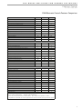
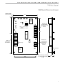
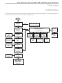
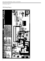
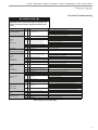
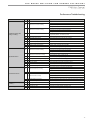
CXM CONTROLS
CXM Digital
Heat Pump Controller
Application, Operation
& Maintenance
97B0003N12
Rev.: 03 January, 2011
CXM Electronic Controls Features Comparison
3
CXM Electronic Heat Pump Control
4
CXM Physical Dimensions & Layout
5
CXM Controls
6
CXM Service & Application Notes
10
Troubleshooting Information
12
Troubleshooting Chart
13
CXM Wiring Diagram
14
Functional Troubleshooting
15
Performance Troubleshooting
17
Revision History
20
WATER-SOURCE HEAT PUMPS
CXM Unit Control
R e v. : 0 3 J a n u a r y, 2 0 1 1
This Page Intentionally Left Blank
2
THE SMART SOLUTION FOR ENERGY EFFICIENCY
CXM Unit Control
R e v. : 0 3 J a n u a r y, 2 0 1 1
CXM Electronic Controls Features Comparison
Basic Features
CXM
CXM-Lon
High and Low Refrigerant Pressure Protection
S
S
S
Water Coil Low Temperature Cutout
S
S
S
True 24VA Thermostat Signals
S
S
S
Thermostat Inputs Compatible with Triacs
S
S
S†
†
†
CXM-MPC
Condensate Overflow Sensor
S
S
S
Anti-Short-Cyle Time Delay
S
S
S
Random Start
S
S
S
Alarm (selectable dry contact or 24VA)
S
S
S
Water Valve Relay
Water Valve Relay with Compressor Delay
S
S
S
N/A
N/A
N/A
Emergency Shutdown
N/A
DDC
DDC
Night Setback with Override
N/A
DDC
DDC
Outdoor Air Damper Control
N/A
N/A
N/A
Advanced Features
Intelligent Reset
S
S
S
High and Low Voltage Protection
S
S
S
Air Coil Low Temperature Cutout
S
S
S
Low Temperature Setpoint Field Select (water, antifreeze)
S
S
S
Electric Heat Control Outputs
S
S
S
Boilerless Electric Heat Control
N/A
N/A
N/A
Intelligent Reversing Valve Operation
N/A
DDC
DDC
High/Low Fan Speed Outputs
N/A
N/A
N/A
Intelligent Fan Speed Control
N/A
N/A
N/A
N/A
Thermostat Type Select (Y,O or Y,W)
N/A
N/A
Reversing Valve Signal Select (O or B)
N/A
N/A
N/A
Dehumidistat Input
N/A
N/A
N/A
Reheat Dehumidification Control*
N/A
N/A
N/A
Multiple Units on One Thermostat/Wall Sensor
N/A
DDC
DDC
Service and Reliability Features
Service Test Mode
S
S
S
LED Fault and Status Lights
S
S
S
Fault Memory after Reset
S
S
S
Unit Performance Sentinel
S
S
S
Harness-Type Factory Wiring Connections
S
S
S
Fully Noise-Tested Design
S
S
S
CE Approval
S
S
S
N/A
N/A
N/A
N/A
S
N/A
BACNET Compliant
N/A
N/A
S
Johnson N2 Compliant
N/A
N/A
S
Removable Low Voltage Connector
DDC / Energy Management Features
Echelon LonMark Compliant
Modbus Compliant
N/A
N/A
S
Leaving Air and Water Temperature Sensor
N/A
S
S
Digital Wall Sensor
N/A
O
O
S = Standard
O = Optional
DDC = Feature can be provided by DDC System
CXM-Lon = CXM with LonMark Module
CXM-MPC = CXM with MPC Module
* = Check with your Factory Representative for model availability
MPC = Multiple ProtoCol (BACNET, N2, Modbus)
† = Compatible with our thermostats. For customer supplied thermostat, check with Controls Engineering Department for approval.
3
WATER-SOURCE HEAT PUMPS
CXM Unit Control
R e v. : 0 3 J a n u a r y, 2 0 1 1
CXM Electronic Heat Pump Control
CXM Overview
The CXM electronic control is a microprocessor based
heat pump controller that is simple to use, yet provides
all the necessary features to improve the operation and
safety of water source heat pumps.
Grounding
The control board is grounded through two of the
metal standoffs.
Field connection ratings for the CXM control:
‘A’ terminal: 20VA at 24VAC.
CXM Controller Part Number:
17B0001N01 CXM Control Board
Product Specification Features
• Anti-short cycle protection
• High and low pressure cutouts
• Water coil low temperature cut-out
• Air coil low temperature cut-out
• Random start
• Unit Performance Sentinel
• Over/under voltage protection
• Diagnostic LED
• Reset lockout at unit or disconnect
• Intelligent reset
• Condensate overflow sensor
• Test Mode
• Electric heat outputs
• Accessory water valve connection
General Operating Parameters
The following are general operating parameters for the
CXM control:
• Operating Environment: -40°F to 176°F and up to 95%
relative humidity, non-condensing.
• Storage Environment: -40°F to 185°F and up to 95%
relative humidity, non-condensing.
Power Requirements:
• CXM only power draw • Normally 5 VA draw at 24VAC.
• Maximum 9 VA draw at 24VAC.
• A dedicated 24VAC, 50-60Hz, 1Ph, 40VA transformer
minimum is required for typical WSHP application.
Relay Contact Ratings
The following relays are mounted on the CXM control:
• Compressor Relay: 40VA at 24VAC.
• Alarm Relay: 28VA at 24VAC.
4
THE SMART SOLUTION FOR ENERGY EFFICIENCY
CXM Unit Control
R e v. : 0 3 J a n u a r y, 2 0 1 1
CXM Physical Dimensions & Layout
Factory 0.250”
Quick Connects
4.00”
BR
C
R
BRG
Test
CCG
CC
Off On
Comp
Relay
5 Dip SW
JW3
JW2
1
FP1 Low Temp
FP2 Low Temp
Y
6.00”
Field
Thermostat
Connections
Y
W
O
G
R
C
AL1
AL2
A
Micro
12
Status
LED
JW1- AL2 Dry
P2
HP
HP
LP
LP
FP1
FP1
FP2
FP2
RV
RV
CO
CO
P3
1 24Vdc
EH1
4 EH2
P1
Alarm
Relay
Factory Low
Voltage Molex
connector for unit
harness
5.50”
Factory Low
Voltage Molex
connector for
electric heat
harness
3/8” standoff
CO
3.50”
Use 4 Mounting Screws:
#6 sheet metal screw
1” long
1.50”
Rev: 6/7/10
5
WATER-SOURCE HEAT PUMPS
CXM Unit Control
R e v. : 0 3 J a n u a r y, 2 0 1 1
CXM Controls
Field Selectable Inputs
Test Mode - Test Mode allows the service personnel to
check the operation of the control in a timely manner. By
momentarily shorting the test terminals, the CXM control
enters a 20 minute Test Mode period in which all time
delays are sped up 15 times. Upon entering Test Mode,
the Status LED will flash a code representing the last
fault. For diagnostic ease at the thermostat, the Alarm
Relay will also cycle during Test Mode. The Alarm Relay
will cycle on and off similar to the status LED to indicate a
code representing the last fault, at the thermostat.
Note: Code 1 indicates there is no fault in memory;
stated differently, the control has not faulted since
the last power-down to power-up sequence.
Test Mode can be exited by shorting the test terminals
for 3 seconds.Test Mode can also be entered and exited
by cycling the G input, 3 times within a 60 second time
period.
During Test Mode, the control monitors to see if the FP1
and FP2 thermistors are in the appropriate place. If the
control is in Test Mode, the control will lockout with Code
9 after 30 seconds if:
the compressor is On in Cooling Mode and the FP1
sensor is colder than the FP2 sensor, or,
the compressor is On in Heating Mode and the FP2
sensor is colder than the FP1 sensor.
Table 1: LED & Alarm Relay Operations
Description of Operation
LED
Alarm
Normal Mode
ON
Normal Mode w/UPS Warning
ON
CXM is non-functional
Fault Retry
Lockout
OFF
Slow Flash
Fast Flash
Over/Under Voltage Shutdown
Slow Flash
Test Mode - No Fault in Memory
Test Mode - HP Fault in Memory
Test Mode - LP Fault in Memory
Test Mode - FP1 Fault in Memory
Test Mode - FP2 Fault in Memory
Test Mode - CO Fault in Memory
Test Mode - Over/Under
Shutdown in Memory
Test Mode - UPS in Memory
Test Mode - Swapped Thermistor
Flashing Code 1
Flashing Code 2
Flashing Code 3
Flashing Code 4
Flashing Code 5
Flashing Code 6
Cycle (Closed 5 seconds,
Open 25 seconds)
Open
Open
Closed
Open (Closed after 15
Minutes)
Cycling Code 1
Cycling Code 2
Cycling Code 3
Cycling Code 4
Cycling Code 5
Cycling Code 6
Open
Flashing Code 7
Cycling Code 7
Flashing Code 8
Flashing Code 9
Cycling Code 8
Cycling Code 9
Special Notes and Examples:
- Slow Flash = 1 flash every 2 seconds
- Fast Flash = 2 flashes every 1 second
- Flash code 2 = 2 quick flashes, 10 sec. pause,
2 quick flashes, 10 sec. pause, etc.
- On pulse 1/3 sec.; off pulse 1/3 sec.
6
Retry Mode - If the control is attempting a retry of a
fault, the status LED will slow flash (slow flash = one flash
every 2 seconds) to indicate the control is in process of
retrying.
Note: In the following field configuration options,
jumper wires should be clipped ONLY when power is
removed from the CXM control.
Water Coil Low Temperature Cut-Out Limit Setting Jumper 3 (JW3-FP1 Low Temp) provides field selection of
temperature limit setting for FP1 to be 30°F or 10°F.
Not Clipped = 30°F. Clipped = 10°F.
Air Coil Low Temperature Cut-Out Limit Setting Jumper 2 (JW2-FP2 Low Temp) provides field selection of
temperature limit setting for FP2 to be 30°F or 10°F.
Not Clipped = 30°F. Clipped = 10°F.
Alarm Relay Setting - Jumper 1 (JW1-AL2 Dry) provides
field selection of Alarm Relay terminal AL2 to be
jumpered to 24VAC or to be dry (no connection).
Not Clipped = AL2 connected to R. Clipped = AL2 dry
contacts (no connection).
DIP Switches
Note: In the following field configuration options, DIP
switches should only be moved when power is removed
from the CXM control, to ensure proper operation.
DIP Switch 1: Unit Performance Sentinel Disable provides field selection to disable the UPS feature.
On = Enabled. Off = Disabled.
DIP Switch 2: Stage 2 Selection - provides selection of
whether the compressor has an on delay. If set to stage
2, the compressor will have a 3 second delay before
energizing. Also, if set for stage 2, the Alarm Relay will
NOT cycle during Test Mode.
On = Stage 1. Off = Stage 2
DIP Switch 3: - Not Used.
DIP Switch 4: DDC Output at EH2 - provides selection
for DDC operation. If set to DDC Output at EH2, the EH2
terminal will continuously output the last fault code of the
controller. If set to EH2 Normal, then the EH2 will operate
as standard electric heat output.
On = EH2 Normal. Off = DDC Output at EH2.
THE SMART SOLUTION FOR ENERGY EFFICIENCY
CXM Unit Control
R e v. : 0 3 J a n u a r y, 2 0 1 1
NOTE: Some CXM controls only have a 2 position DIP
switch package. If this is the case, then this option can
be selected by clipping the jumper which is in position
4 of SW1:
Jumper not clipped = EH2 Normal. Jumper clipped =
DDC Output at EH2.
DIP Switch 5: Factory Setting - Normal position is ON.
Do not change selection unless instructed to do so by
the Factory.
Safety Features
The following safety features are provided to protect
the compressor, heat exchangers, wiring and other
components from damage caused by operation outside
of design conditions.
Anti-Short Cycle Protection - The control features a 5
minute anti-short cycle protection for the compressor.
Note: The 5 minute anti-short cycle also occurs at
power up.
Random Start - The control features a 5-80 second
random start upon power up.
Extended Compressor Operation Monitoring - If the
compressor relay has been on for 4 continuous hours,
then the control will automatically turn off the compressor
relay and wait the short cycle protection time. All
appropriate safeties including the LP will be monitored
during the off time. If all operation is normal, and if the
compressor demand is still present, the control will turn
the compressor back on.
Fault Retry - In Fault Retry Mode, the Status LED begins
slow flashing to signal that the control is trying to recover
from a fault input. The CXM control will stage off the
outputs and then “try again” to satisfy the thermostat "Y"
input call. Once the thermostat input calls are satisfied,
the control will continue on as if no fault occurred. If 3
consecutive faults occur without satisfying the thermostat
"Y" input call, then the control will go into Lockout Mode.
The last fault causing the lockout will be stored in memory
and can be viewed by going into Test Mode.
Note: If “1 Try” is selected for FP1 and FP2, then
there will be no “retries” for FP1 and FP2 faults. The
control will only try one time for these faults.
� CAUTION! �
CAUTION! Do not restart units without inspection and
remedy of faulting condition. Equipment damage may occur.
Lockout Mode can be soft reset via the thermostat “Y”
input or can be hard reset via the disconnect. The last fault
causing the lockout will be stored in memory and can be
viewed by going into Test Mode.
Lockout with Emergency Heat - While in Lockout Mode,
if W becomes active, then Emergency Heat Mode will
occur.
High Pressure Switch - When the high pressure switch
opens due to high refrigerant pressures, the compressor
relay is de-energized immediately since the high pressure
switch is in series with the compressor contactor coil. The
High Pressure Fault recognition is immediate as well.
High Pressure Lockout Code = 2
Example: 2 quick flashes, 10 sec. pause, 2 quick flashes,
10 sec. pause, etc.
Low Pressure Switch - The low pressure switch must be
open and remain open for 30 continuous seconds during
ON cycle to be recognized as a Low Pressure fault. If
the low pressure switch is open for 30 seconds prior to
compressor power up it will be considered a low
pressure (loss of charge) fault. The low pressure switch
input is bypassed for the initial 120 seconds of a
compressor run cycle.
Low Pressure Lockout Code = 3
Water Coil Low Temperature Cut-Out Limit (FP1) - The
control will recognize an FP1 fault, during a compressor
run cycle if:
a) the thermistor temperature is below the selected low
temperature protection limit setting, and,
b) the thermistor temperature is rising (getting warmer)
at a rate LESS than 2°F per 30 second time period.
The FP1 input is bypassed for the initial 120 seconds
of a compressor run cycle.
FP1 Lockout Code = 4
Lockout - In Lockout Mode, the Status LED will begin fast
flashing. The compressor relay is turned off immediately.
7
WATER-SOURCE HEAT PUMPS
CXM Unit Control
R e v. : 0 3 J a n u a r y, 2 0 1 1
Air Coil Low Temperature Cut-Out Limit (FP2) - The
control will recognize an FP2 fault, during a compressor
run cycle if:
a) the thermistor temperature is below the selected low temperature protection limit setting, AND
b) the thermistor temperature is rising (getting warmer)
at a rate LESS than 2F per 30 second time period.
Swapped FP1/FP2 Thermistors - During Test Mode, the
control monitors to see if the FP1 and FP2 thermistors are
in the appropriate place. If the control is in Test Mode,
the control will lockout, with Code 9, after 30 seconds if:
a) the compressor is On in Cooling Mode and the FP1
sensor is colder than the FP2 sensor. Or,
b) the compressor is On in Heating Mode and the FP2
sensor is colder than the FP1 sensor.
The FP2 input is bypassed for the initial 120 seconds of a
compressor run cycle.
Swapped FP1/FP2 Thermistor Code = 9.
FP2 Lockout Code = 5
Condensate Overflow - The Condensate Overflow
sensor must sense overflow levels for 30 continuous
seconds to be recognized as a CO fault. Condensate
Overflow will be monitored during compressor run cycle.
CO Lockout Code = 6
Over/Under Voltage Shutdown - An Over/Under Voltage
condition exists when the control voltage is outside
the range of 18VAC to 31.5VAC. Over/Under Voltage
Shutdown is self resetting in that if the voltage comes back
within range of 18.5VAC to 31VAC for at least 0.5 seconds,
then normal operation is restored. This is not considered
a fault or lockout. If the CXM is in Over/Under Voltage
Shutdown for 15 minutes, the Alarm Relay will close.
Diagnostic Features - The Status LED on the CXM
control advises the serviceman of the current status of
the CXM control. The status LED can display either the
current CXM Mode or the last fault memory if in Test
Mode. See Table 1 for a complete listing of codes. If the
fault type is "Primary" (HP, LP, FP1, FP2, or CO) then the
fault type will always be retained in memory (Primary
faults will overwrite Secondary faults). If the fault type is
"Secondary" (Over/Under Voltage, UPS or Swapped FP1/
FP2) then the fault type will only be retained if there are
no "Primary" faults in memory. The Secondary fault types
will not "overwrite" the Primary fault memory.
Unit Operation Description
Over/Under Voltage Shutdown Code = 7
PowerUp - The unit will not operate until all the inputs
and safety controls are checked for normal conditions.
Note: The compressor will have a 5 minute anti-short
cycle delay at power-up.
Unit Performance Sentinel - UPS (patent pending) - The
UPS feature warns when the heat pump is operating
inefficiently. A UPS condition exists when:
Standby - In Standby Mode, Y and W inputs are not
active. Inputs O and G may be active. Compressor will
be off.
a) in Heating Mode with compressor energized, if FP2 is
greater than 125°F for 30 continuous seconds, or
b) in Cooling Mode with compressor energized, if FP1
is greater than 125°F for 30 continuous seconds, OR
FP2 is less than 40°F for 30 continuous seconds.
Cooling - To enter Cooling Mode, Y and O become
active. The first time after power-up that there is a call
for compressor, the compressor will follow a 5 to 80
second random start delay. There will also be a 5 minute
compressor anti-short cycle protection time as well. After
the random start delay and the anti-short cycle delay,
the compressor relay is energized. On all subsequent
compressor calls, the random start delay is omitted.
If a UPS condition occurs, the control will immediately go
to UPS warning. The status LED will remain on as if the
control is in Normal Mode. (see "LED and Alarm Relay
Operation Table" ). Outputs of the control, excluding
LED and Alarm Relay, will NOT be affected by UPS. The
UPS condition cannot occur during a compressor off
cycle. During UPS warning, the Alarm Relay will cycle on
and off. The cycle rate will be On for 5 seconds, Off for 25
seconds, On for 5 seconds, Off for 25 seconds, etc.
Unit Performance Sentinel Warning Code = 8
8
THE SMART SOLUTION FOR ENERGY EFFICIENCY
CXM Unit Control
R e v. : 0 3 J a n u a r y, 2 0 1 1
Heating Stage 1 - To enter Heating Stage 1 Mode, Y
becomes active. The first time after power-up that there is
a call for compressor, the compressor will follow a 5 to 80
second random start delay. There will also be a 5 minute
compressor anti-short cycle protection time as well. After
the random start delay and the anti-short cycle delay,
the compressor relay is energized. On all subsequent
compressor calls, the random start delay is omitted.
Heating Stage 2 - To enter Heating Stage 2 Mode, W
becomes active (Y already active). The G input must
be active or the W input is ignored. The compressor
relay remains on. EH1 is turned on immediately. With
continuing Heating Stage 2 demand, EH2 will turn on
after 10 minutes. The EH2 will not turn on (or will turn off
if already on) if FP1 temperature is greater than 45°F and
FP2 is greater than 110°F.
Emergency Heat - In Emergency Heat Mode, W
becomes active while Y is not active. The G input must
be active or the W input is ignored. EH1 is turned on
immediately. With continuing Emergency Heat demand,
EH2 will turn on after 5 minutes. The FP1 and FP2
temperatures do not effect emergency heat operation.
Table 1a: Fault Description Table
Fault
Fault
LED Code
Fault Condition
No Fault in Memory
1
There has been no fault
detected since the last power
down/power up sequence
High Pressure Switch
2
HP Open Instantly
Low Pressure Switch
or LOC
3
LP open for 30 continuous
seconds before or during a call
(bypassed for first 120 seconds)
Low Temperature
Cut-Out Coax - FP1
4
FP1 below Temp limit for 30
continuous seconds (bypassed
for first 120 seconds of
operation)
Low Temperature
Cut-Out Aircoil - FP2
5
FP2 below Temp limit for 30
continuous seconds (bypassed
for first 120 seconds of
operation)
Condensate Overflow
6
Sense overflow (grounded) for
30 continuous seconds
Over/Under Voltage
Shutdown
7
(Autoreset)
“R” power supply is <18VAC or
>31.5VAC
UPS Warning
8
Unit Performance Warning
signal has occurred
Swapped FP1/FP2
9
FP1 and FP2 are in
reversed positions
Engineering Guide Specifications
The following engineering guide specifications for the
CXM control should be a part of all product submittals.
CXM Control
A microprocessor-based compressor controller (CXM)
shall be provided to monitor and control unit operation.
The control shall provide compressor and electric heater
sequencing, high and low pressure monitoring, field
selectable water and air coil low temperature cut-out
sensing, condensate overflow sensing, over/under
voltage monitoring, and unit performance sentinel. The
control shall also provide for water valve connection, a
Test Mode, short cycle protection, random start-up, as
well as fault LED, fault memory, and intelligent fault retry.
The control shall employ a quick attach harness assembly
for low voltage connections to the CXM control board
to aid in troubleshooting or replacement. An integral
terminal block with screw terminals shall be provided on
the CXM control for all field low voltage connections.
9
WATER-SOURCE HEAT PUMPS
CXM Unit Control
R e v. : 0 3 J a n u a r y, 2 0 1 1
CXM Service & Application Notes
Table 2: 1% Sensor Calibration Points
CXM Sensors
Pressure Switches
All pressure switches are designed to be normally closed
during normal operating conditions, and to open upon
fault.
Temp
(°F)
Minimum
Resistance
(Ohm)
Maximum
Resistance
(Ohm)
Nominal
Resistance
(Ohm)
78.5
9523
9715
9619
77.5
9650
9843
9746
Condensate Sensor
The Condensate Sensor input will fault upon sensing
impedance less than 100,000 Ohms for 30 continuous
seconds. The recommended design uses a single wire
terminated with a male 1/4" quick connect located in the
drain pan at desired trip level. Upon a high condensate
level the water will short between the air coil and the
quick connect producing a resistance less than 100,000
Ohms. Since condensate is free of impurities, it has no
conductivity. Only the impurities from the drain pan
and coil dust or dirt create the conductance. A second
ground wire with appropriate terminal to the drain
pan can be used with the control to replace the air coil
ground path. The Condensate Sensor can also essentially
be any open contact that closes upon a fault condition.
76.5
10035
10236
10135
75.5
10282
10489
10385
33.5
30975
31598
31285
32.5
31871
32512
32190
31.5
32653
33310
32980
30.5
33728
34406
34065
1.5
80624
82244
81430
0.5
83327
85002
84160
0.0
84564
86264
85410
Chart 1: Thermistor Nominal Resistance
Thermistor Temperature Sensors
The thermistor is available in the following configurations
shown in Table 2. The thermistor is an NTC (negative
temperature coefficient) type. The sensor has a 1%
tolerance and follows the Table 2 and Chart 2 shown.
Table 4 shows the nominal resistance at any given
temperature and can be used for field service reference.
The sensor will use a minimum of 24 awg wire and be
epoxy embedded in the beryllium copper clip.
Table 3: Replacement Thermistor FP1, FP2 Part Numbers
Thermistor
Type
FP1 (Gray)
FP2 (Violet)
10
Tube OD
Lead Length (in.)
36
48
96
192
3/8, 1/2
17B0027N06
N/A
17B0027N04
N/A
5/8, 7/8
N/A
N/A
17B0026N01
N/A
3/8, 1/2
N/A
17B0026N02
N/A
17B0005N05
5/8, 7/8
N/A
N/A
N/A
17B0026N02
THE SMART SOLUTION FOR ENERGY EFFICIENCY
CXM Unit Control
R e v. : 0 3 J a n u a r y, 2 0 1 1
Table 4: Nominal Resistance at Various Temperatures
Temp
(°C)
Temp
(°F)
Resistance
(kOhm)
Temp
(°C)
Temp
(°F)
Resistance
(kOhm)
CXM Thermostat Details
Thermostat Compatibility - Most all heat pump
thermostats can be used with the CXM control. However
Heat/Cool stats are NOT compatible with the CXM.
Anticipation Leakage Current - Maximum leakage current
for "Y" is 50 mA and for "W" is 20mA. Triacs can be used
if leakage current is less than above. Thermostats with
anticipators can be used if anticipation current is less
than that specified above.
Thermostat Signals
• "Y" and "W" have a 1 second recognition time when
being activated or being removed.
• "O" and "G" are direct pass through signals but are
monitored by the micro processor.
• "R" and "C" are from the transformer.
• "AL1" and "AL2" originate from the Alarm Relay.
• "A" is paralleled with the compressor output for use
with well water solenoid valves.
• The "Y" 1/4" quick connect is a connection point to
the "Y" input terminal P1 for factory use. This "Y"
terminal can be used to drive panel mounted relays
such as the loop pump relay.
Safety Listing
The CXM control is listed under the UL Standard for
limit controls and is CE listed under EN50081-1 and
EN61000-3.
11
WATER-SOURCE HEAT PUMPS
CXM Unit Control
R e v. : 0 3 J a n u a r y, 2 0 1 1
Troubleshooting Information
General - CXM board troubleshooting in general is
best summarized as simply verifying inputs and outputs.
After this process has been verified, confidence in
board operation is confirmed and the trouble must be
elsewhere. Below are some general guidelines required
for developing training materials and procedures when
applying the CXM Control.
CXM Field Inputs - All inputs are 24VAC from the
thermostat and can be verified using a Volt meter
between C and Y, G, O, W. See the I/O reference table
(table 5).
Sensor Inputs - All sensor inputs are 'paired wires'
connecting each component with the board. Therefore
continuity on pressure switches can be checked at the
board connector.
The thermistor resistance should be measured with the
connector removed so that only the impedance of the
thermistor is measured. If desired this reading can be
compared to the chart shown in the thermistor section
of this manual based upon the actual temperature of
the thermistor clip. An ice bath can be used to check
calibration of a thermistor if needed.
CXM Outputs - The compressor relay is 24VAC and can
be verified using a voltmeter. The fan signal is passed
through the board to the external fan relay. The alarm
relay can either be 24VAC as shipped or dry contacts
(measure continuity during fault) for use with DDC by
clipping the J1 jumper. Electric heat outputs are 24VDC
and require a voltmeter set for DC to verify operation.
When troubleshooting, measure from 24VDC terminal to
EH1 or EH2 terminals. See the I/O reference table.
Test Mode - Test Mode can be entered for 20 minutes
by shorting the test pins. For diagnostic ease at the
thermostat, the alarm relay will also cycle during Test
Mode. The alarm relay will cycle on and off similar to the
fault LED to indicate a code representing the last fault,
at the thermostat. Test Mode can also be entered and
exited by cycling the G input, 3 times within a 60 second
time period.
Table 5: CXM Input/Output Reference Table
Connection
R
C
Y
W
O
G
AL1
AL2
A
BR
BRG
CC
CCG
HP
LP
FP1
FP2
RV
CO
24VDC
W1
W2
12
Input or
Output
I
I
I
I
O
O
O
O
O
O
O
I
I
I
I
O
I
O
O
O
Description
24 VAC
24 VAC (grounded common)
Connect to thermostat - Y output call for compressor
Connect to thermostat - W output call for Htg2 or Emerg Ht
Connect to thermostat - 0 output call for reversing valve with cooling
Connect to thermostat - G output call for fan
Connect to thermostat fault light - 24VAC or dry alarm
Alarm Relay 24VAC or dry
Output for water solenoid valve - paralleled with compressor contactor coil
Connection for blower relay-direct connect from G
Blower relay common connection
Connection for compressor contactor
Compressor contactor common connection
High Pressure Switch input terminals
Low Pressure Switch input terminals
Water Coil Low Temperature Thermistor Input
Air Coil Low Temperature Thermistor Input
Reversing Valve Output Terminals - direct connect from "O"
Condensate overflow input terminals
24 VDC supply to electric heat module
Output terminal for stage 1 electric heat
Output terminal for stage 2 electric heat
THE SMART SOLUTION FOR ENERGY EFFICIENCY
CXM Unit Control
R e v. : 0 3 J a n u a r y, 2 0 1 1
Troubleshooting Chart
Use the following troubleshooting flow chart to find appropriate troubleshooting strategies on the following pages for
the CXM control and most water source heat pump applications.
Start
Did unit
attempt to
start?
No
Did unit
lockout at
start-up?
No
Yes
Check main power
(see power problems)
Yes
See "Unit
short
cycles"
Yes
See "Only
fan runs"
Yes
See "Only
comp
runs"
See "Does
not operate
in clg"
Unit short
cycles?
See HP
Fault
No
Yes
Only fan
runs?
No
Only
compressor
runs?
No fault
shown
Check fault LED code
on control board
See FP2
Fault
See
LP/LOC
Fault
See FP1
Fault
See
Condensate
Fault
Replace
CXM/
DXM
CXM
See Over/
Under
Voltage
No
No
Did unit lockout Yes
after a period of
operation?
No
Does unit
operate in
cooling?
Yes
Unit is OK!
"See Performance
Troubleshooting" for
further help
13
WATER-SOURCE HEAT PUMPS
CXM Unit Control
R e v. : 0 3 J a n u a r y, 2 0 1 1
CXM Wiring Diagram
14
THE SMART SOLUTION FOR ENERGY EFFICIENCY
CXM Unit Control
R e v. : 0 3 J a n u a r y, 2 0 1 1
Functional Troubleshooting
� CAUTION! �
CAUTION! Do not restart units without inspection and
remedy of faulting condition. Equipment damage may
occur.
Fault
Main power problems
HP Fault
Code 2
Htg Clg Possible Cause
Air temperature out of range in heating
Overcharged with refrigerant
Bad HP Switch
Insufficient charge
Check line voltage circuit breaker and disconnect.
Check for line voltage between L1 and L2 on the contactor.
Check for 24VAC between R and C on CXM/DXM'
Check primary/secondary voltage on transformer.
Check pump operation or valve operation/setting.
Check water flow adjust to proper flow rate.
Bring water temp within design parameters.
Check for dirty air filter and clean or replace.
Check fan motor operation and airflow restrictions.
Dirty Air Coil- construction dust etc.
Too high of external static. Check static vs blower table.
Bring return air temp within design parameters.
Check superheat/subcooling vs typical operating condition table.
Check switch continuity and operation. Replace.
Check for refrigerant leaks
X
Compressor pump down at start-up
Check charge and start-up water flow.
X
Reduced or no water flow in heating
X
Inadequate antifreeze level
Improper temperature limit setting (30°F vs
10°F [-1°C vs -2°C])
Water Temperature out of range
X
X
Green Status LED Off
X
Reduced or no water flow in cooling
X
Water Temperature out of range in cooling
Reduced or no air flow in heating
X
High Pressure
LP/LOC Fault
Code 3
X
X
X
X
X
X
X
Low Pressure / Loss of Charge
LT1 Fault
Code 4
Water coil low
temperature limit
X
X
X
Bad thermistor
X
Reduced or no air flow in cooling
X
X
X
X
Air Temperature out of range
Improper temperature limit setting (30°F vs
10°F [-1°C vs -12°C])
Bad thermistor
Blocked drain
Improper trap
X
Poor drainage
X
x
X
X
X
Moisture on sensor
Plugged air filter
Restricted Return Air Flow
X
X
Under Voltage
X
X
X
LT2 Fault
Code 5
Air coil low
temperature limit
X
X
X
X
Condensate Fault
Code 6
Over/Under
Voltage Code 7
(Auto resetting)
Unit Performance Sentinel
Code 8
No Fault Code Shown
Solution
X
X
X
X
X
X
X
X
Over Voltage
Heating mode FP2>125°F [52°C]
Cooling Mode FP1>125°F [52°C] OR FP2<
40ºF [4ºC])
No compressor operation
Compressor overload
Control board
Check pump operation or water valve operation/setting.
Plugged strainer or filter. Clean or replace..
Check water flow adjust to proper flow rate.
Check antifreeze density with hydrometer.
Clip JW3 jumper for antifreeze (10°F [-12°C]) use.
Bring water temp within design parameters.
Check temp and impedance correlation per chart
Check for dirty air filter and clean or replace.
Check fan motor operation and airflow restrictions.
Too high of external static. Check static vs blower table.
Too much cold vent air? Bring entering air temp within design parameters.
Normal airside applications will require 30°F [-1°C] only.
Check temp and impedance correlation per chart.
Check for blockage and clean drain.
Check trap dimensions and location ahead of vent.
Check for piping slope away from unit.
Check slope of unit toward outlet.
Poor venting. Check vent location.
Check for moisture shorting to air coil.
Replace air filter.
Find and eliminate restriction. Increase return duct and/or grille size.
Check power supply and 24VAC voltage before and during operation.
Check power supply wire size.
Check compressor starting. Need hard start kit?
Check 24VAC and unit transformer tap for correct power supply voltage.
Check power supply voltage and 24VAC before and during operation.
Check 24VAC and unit transformer tap for correct power supply voltage.
Check for poor air flow or overcharged unit.
Check for poor water flow, or air flow.
See "Only Fan Operates".
Check and replace if necessary.
Reset power and check operation.
Table Continued on Next Page
15
WATER-SOURCE HEAT PUMPS
CXM Unit Control
R e v. : 0 3 J a n u a r y, 2 0 1 1
Fault
Unit Short Cycles
Only Fan Runs
Only Compressor Runs
Unit Doesn’t Operate
in Cooling
16
Htg Clg Possible Cause
X
X
X
X
X
X
X
X
X
X
X
X
X
X
Dirty air filter
Unit in "test mode"
Unit selection
Compressor overload
Thermostat position
Unit locked out
Compressor Overload
X
X
Thermostat wiring
X
X
Thermostat wiring
X
X
X
X
X
X
Fan motor
X
X
Thermostat wiring
X
Reversing valve
X
X
Thermostat setup
Thermostat wiring
X
Thermostat wiring
Fan motor relay
Solution
Check and clean air filter.
Reset power or wait 20 minutes for auto exit.
Unit may be oversized for space. Check sizing for actual load of space.
Check and replace if necessary
Ensure thermostat set for heating or cooling operation.
Check for lockout codes. Reset power.
Check compressor overload. Replace if necessary.
Check thermostat wiring at heat pump. Jumper Y and R for compressor operation
in test mode.
Check G wiring at heat pump. Jumper G and R for fan operation
Jumper G and R for fan operation. Check for Line voltage across BR contacts.
Check fan power enable relay operation (if present).
Check for line voltage at motor. Check capacitor.
Check thermostat wiring at heat pump. Jumper Y and R for compressor operation
in test mode
Set for cooling demand and check 24VAC on RV coil and at CXM/DXM board.
If RV is stuck, run high pressure up by reducing water flow and while operating
engage and disengage RV coil voltage to push valve.
Check for ‘O’ RV setup not ‘B’.
Check O wiring at heat pump. Jumper O and R for RV coil ‘click’.
Put thermostat in cooling mode. Check 24 VAC on O (check between C and
O); check for 24 VAC on W (check between W and C). There should be voltage
on O, but not on W. If voltage is present on W, thermostat may be bad or wired
incorrectly.
THE SMART SOLUTION FOR ENERGY EFFICIENCY
CXM Unit Control
R e v. : 0 3 J a n u a r y, 2 0 1 1
Performance Troubleshooting
Performance Troubleshooting
Htg Clg Possible Cause
X
X
Dirty filter
Solution
Replace or clean.
Check for dirty air filter and clean or replace.
Reduced or no air flow in heating
X
Check fan motor operation and airflow restrictions.
Too high of external static. Check static vs. blower table.
Check for dirty air filter and clean or replace.
X
Reduced or no air flow in cooling
Check fan motor operation and airflow restrictions.
Leaky duct work
Check supply and return air temperatures at the unit and at distant duct registers
if significantly different, duct leaks are present.
Too high of external static. Check static vs. blower table.
Insufficient capacity/ Not
cooling or heating
X
X
X
X
Low refrigerant charge
Check superheat and subcooling per chart.
X
X
Restricted metering device
Check superheat and subcooling per chart. Replace.
X
Defective reversing valve
Perform RV touch test.
X
Thermostat improperly located
Check location and for air drafts behind stat.
X
X
X
Unit undersized
Recheck loads & sizing. Check sensible clg. load and heat pump capacity.
X
X
Scaling in water heat exchanger
Perform scaling check and clean if necessary.
X
X
Inlet water too hot or too cold
Check load, loop sizing, loop backfill, ground moisture.
Check for dirty air filter and clean or replace.
Reduced or no air flow in heating
X
Check fan motor operation and air flow restrictions.
Too high of external static. Check static vs. blower table.
High Head Pressure
Check pump operation or valve operation/setting.
X
Reduced or no water flow in cooling
X
Inlet water too hot
Check load, loop sizing, loop backfill, ground moisture.
Air temperature out of range in heating
Bring return air temperature within design parameters.
X
Check water flow. Adjust to proper flow rate.
X
Scaling in water heat exchanger
Perform scaling check and clean if necessary.
X
X
Unit overcharged
Check superheat and subcooling. Re-weigh in charge.
X
X
Non-condensables in system
Vacuum system and re-weigh in charge.
X
X
Restricted metering device.
Check superheat and subcooling per chart. Replace.
Check pump operation or water valve operation/setting.
X
Reduced water flow in heating.
Plugged strainer or filter. Clean or replace.
X
Water temperature out of range.
Bring water temperature within design parameters.
Check water flow. Adjust to proper flow rate.
Check for dirty air filter and clean or replace.
Low Suction Pressure
X
Reduced air flow in cooling.
Check fan motor operation and air flow restrictions.
X
Air temperature out of range
Too much cold vent air? Bring entering air temperature within design parameters.
X
Insufficient charge
Check for refrigerant leaks.
Too high of external static. Check static vs. blower table.
X
Low Discharge Air Temperature
in Heating
High humidity
X
Too high of air flow
Check fan motor speed selection and air flow chart.
X
Poor performance
See ‘Insufficient Capacity’
X
Too high of air flow
Check fan motor speed selection and airflow chart.
X
Unit oversized
Recheck loads & sizing. Check sensible clg load and heat pump capacity.
17
WATER-SOURCE HEAT PUMPS
CXM Unit Control
R e v. : 0 3 J a n u a r y, 2 0 1 1
Notes:
18
THE SMART SOLUTION FOR ENERGY EFFICIENCY
CXM Unit Control
R e v. : 0 3 J a n u a r y, 2 0 1 1
Notes:
19
WATER-SOURCE HEAT PUMPS
CXM Unit Control
R e v. : 0 3 J a n u a r y, 2 0 1 1
Revision History
Date:
Item:
Action:
01/03/11
Format - All Pages
Updated
06/11/10
Format - All Pages
Updated
06/11/10
CXM Physical Dimensions & Layout
Illustration Updated
10/30/09
Functional Troubleshooting Table
Updated
04/29/09
CXM Physical Dimensions & Layout
FP1 and FP2 Information Corrected
01/5/09
First Published
*97B0003N12*
97B0003N12
We work continually to improve our products. As a result, the design and specifications of each product at the time of order may be changed without
notice and may not be as described herein. Please contact our Customer Service Department at 1-405-745-6000 for specific information on the
current design and specifications. Statements and other information contained herein are not express warranties and do not form the basis of any
bargain between the parties, but are merely our opinion or commendation of its products.
We are a proud supporter of the Geothermal Exchange Organization - GEO. For more information visit geoexchange.org
20
© LSB, Inc. 2008
Rev.: 03 January, 2011