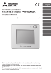
1
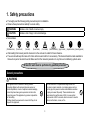
Air Conditioning Control System AHC ADAPTER PAC-IF01AHC-J Installation and Instructions Manual WARNING or Safety notes are marked with CAUTION, depending on the severity of possible consequences that may result when the instructions are not followed exactly as stated. Proper installation is important for your safety and proper functioning of the units. Thoroughly read the following safety precautions prior to installation. To ensure safety and proper operation of the unit, the unit should only be installed by qualified personnel. After reading this manual, pass the manual on to the end user to retain for future reference. The users should keep this manual for future reference and refer to it as necessary. This manual should be made available to those who repair or relocate the units. Make sure that the manual is passed on to any future air conditioning system users. 1.Safety precautions................................................................................ 3 2.Important notice.................................................................................... 9 3.Functions............................................................................................ 10 4.Package contents............................................................................... 12 5.Specifications...................................................................................... 13 5-1. Product specifications of AHC ADAPTER........................................... 13 5-2. External dimensions of AHC ADAPTER.............................................. 14 6.System configuration.......................................................................... 15 7.Installation procedures........................................................................ 16 7-1. Programming....................................................................................... 17 7-2. Installation........................................................................................... 18 7-2-1. Field-supplied items.................................................................. 19 7-2-2. Installation method.................................................................... 20 Method 1: Installation using L-fittings............................................... 21 Method 2: Installation using DIN rail................................................ 22 7-2-3. Wiring connections.................................................................... 24 7-2-3-1. Removing the cover to access the wiring........................... 24 7-2-3-2. Connecting functional ground wire..................................... 25 7-2-3-3. Connecting M-NET transmission cables............................ 26 7-2-3-4. Securing the cables in place.............................................. 27 7-2-3-5. Reinstalling the cover......................................................... 28 7-2-4. Connecting AHC ADAPTER with ALPHA2................................ 29 7-2-5. H/W information (Switch types and display contents)............... 32 7-2-6. Function selection (SW103)...................................................... 33 7-3. Initial settings and Test run.................................................................. 34 7-3-1. Initial settings............................................................................. 34 7-3-2. Test run...................................................................................... 35 7-3-3. Diagnostics with the LED light on the AHC ADAPTER circuit board......................................................................................... 36 8.Error code list...................................................................................... 37 About Advanced HVAC CONTROLLER (AHC) Advanced HVAC CONTROLLER (hereafter referred to as AHC) comprises of MITSUBISHI ELECTRIC’s AHC ADAPTER (PAC-IF01AHC-J) and α2 SIMPLE APPLICATION CONTROLLER* (hereafter referred to as ALPHA2). * α2 SIMPLE APPLICATION CONTROLLER is one of the Programming Logic Controllers that are manufactured by MITSUBISHI ELECTRIC CORPORATION. AHC allows for the connection of MITSUBISHI ELECTRIC’s air conditioning network system (hereafter referred to as M-NET) to other systems, which was not possible with the use of ALPHA2 alone. AHC provides the following functions. 1 Controls external devices using the sensor data of the air conditioning units connected to M-NET. 2 Interlocks the operation of air conditioning units and external devices that are connected to ALPHA2. 3 Controls air conditioning units that are connected to M-NET. 4 Allows for the combined use of the items 1-3 above. 5 Monitors the input/output status of ALPHA2 via a remote controller or a centralized controller. Compatible controllers [As of April 2013 (North America); June 2013 (outside North America)] • Remote Controller: PAR-U01MEDU, PAR-U02MEDA • Centralized Controller: EB-50GU-A, EB-50GU-J * Refer to the manual that came with ALPHA2 for information about ALPHA2. * The use of AHC ADAPTER requires either a remote controller or a centralized controller. 2 1. Safety precautions ●● Thoroughly read the following safety precautions prior to installation. ●● Observe these precautions carefully to ensure safety. WARNING Indicates a risk of death or serious injury. CAUTION Indicates a risk of injury or structural damage. ●● Nomenclature (Prohibited actions) (Do not touch) (No water) (No wet hands) (Fire hazards) (Electric shock hazards) (Injury hazards) (Important actions) (Grounding required) ●● After reading this manual, pass the manual on to the end user to retain for future reference. ●● The users should keep this manual for future reference and refer to it as necessary. This manual should be made available to those who repair or relocate the units. Make sure that the manual is passed on to any future air conditioning system users. All electric work must be performed by qualified personnel. General precautions WARNING This appliance is not intended for use by persons (including children) with reduced physical, sensory or mental capabilities, or lack of experience and knowledge, unless they have been given supervision or instruction concerning use of the appliance by a person responsible for their safety. Children should be supervised to ensure that they do not play with the appliance. Do not install AHC in a place where large amounts of oil, steam, organic solvents, or corrosive gases, such as sulfuric gas, are present or where acidic/alkaline solutions or sprays are used frequently. These substances can compromise the performance of AHC or cause certain components of AHC to corrode, which can result in electric shock, malfunctions, smoke, or fire. 3 To reduce the risk of injury or electric shock, before spraying a chemical around AHC, stop the operation and cover AHC. To reduce the risk of electric shock, malfunctions, smoke or fire, do not operate the switches/buttons or touch other electrical parts with wet hands. To reduce the risk of injury or electric shock, stop the operation and switch off the power supply before cleaning, maintaining, or inspecting AHC. Properly install all required covers to keep moisture and dust out of AHC. Dust accumulation and water can cause electric shock, smoke, or fire. To reduce the risk of shorting, current leakage, electric shock, malfunctions, smoke, or fire, do not wash AHC with water or any other liquid. To reduce the risk of injury, keep children away while installing, inspecting, or repairing AHC. CAUTION To reduce the risk of fire or explosion, do not place flammable materials or use flammable sprays around AHC. To reduce the risk of injury and electric shock, avoid contact with sharp edges of certain parts. To reduce the risk of damage to AHC, do not directly spray insecticide or other flammable sprays on AHC. To reduce the risk of injury, wear protective gear when working on AHC. Precautions during installation WARNING Do not install AHC where there is a risk of leaking flammable gas. If flammable gas accumulates around AHC, it may ignite and cause a fire or explosion. Properly dispose of the packing materials. Plastic bags pose suffocation hazard to children. To prevent injury, install AHC on a flat surface strong enough to support its weight. Take appropriate safety measures against earthquakes to prevent AHC from causing injury. 4 CAUTION To reduce the risk of shorting, current leakage, electric shock, malfunctions, smoke, or fire, do not install AHC in a place exposed to water or in a condensing environment. AHC must be installed by qualified personnel according to the instructions detailed in this manual. Improper installation may result in electric shock or fire. Precautions during wiring WARNING To reduce the risk of damage to AHC, malfunctions, smoke, or fire, do not connect the power cable to the signal terminal block. To reduce the risk of current leakage, overheating, smoke, or fire, use properly rated cables with adequate current carrying capacity. Properly secure the cables in place and provide adequate slack in the cables so as not to stress the terminals. Improperly connected cables may break, overheat, and cause smoke or fire. Proper grounding must be provided by a licensed electrician. Do not connect the protective ground wire to a gas pipe, water pipe, lightning rod, or telephone wire. Improper grounding may result in electric shock, smoke, fire, or malfunction due to electrical noise interference. To reduce the risk of injury or electric shock, switch off the main power before performing electrical work. All electric work must be performed by a qualified electrician according to the local regulations, standards, and the instructions detailed in this manual. Capacity shortage to the power supply circuit or improper installation may result in malfunction, electric shock, smoke, or fire. 5 CAUTION To reduce the risk of electric shock, shorting, or malfunctions, keep wire pieces and sheath shavings out of the terminal block. To reduce the risk of electric shock, malfunctions, or fire, seal the gap between the cable access holes with putty. To reduce the risk of shorting, current leakage, electric shock, or malfunctions, keep the cables out of contact with the AHC edges. Precautions for moving or repairing AHC WARNING CAUTION AHC should be repaired or moved only by qualified personnel. Do not disassemble or modify AHC. Improper installation or repair may cause injury, electric shock, or fire. To reduce the risk of shorting, electric shock, fire, or malfunction, do not touch the circuit board with tools or with your hands, and do not allow dust to accumulate on the circuit board. Additional precautions To avoid damage to AHC, use appropriate tools to install, inspect, or repair AHC. Take appropriate measures against electrical noise interference when installing the air conditioners in hospitals or facilities with radio communication capabilities. Inverter, high-frequency medical, or wireless communication equipment as well as power generators may cause the air conditioning system to malfunction. Air conditioning system may also adversely affect the operation of these types of equipment by creating electrical noise. AHC is designed for exclusive use with the Building Management System by Mitsubishi Electric. The use of AHC for with other systems or for other purposes may cause malfunctions. 6 To reduce the risk of erroneous signal output, malfunctions, and resultant accidents, provide an external safety circuit to ensure a safe operation of the entire system in case problems occur with external power supply or with AHC. To avoid malfunctions, do not bundle power cables and signal cables together, or place them in the same metallic conduit. To reduce the risk of electric shock, turn off the power to AHC before installing or wiring AHC. To reduce the risk of erroneous signal output, malfunctions, and resultant accidents, turn on the power to AHC first before turning on the power to external devices. To avoid causing damage or fire, do not apply an AC voltage or a voltage higher than 32 VDC to the M-NET or the power supply (24 VDC) terminal blocks on AHC ADAPTER. To reduce the risk of smoke and fire that may result from overcurrent continuously transmitted to the output circuit for an extended period of time due to overload current above the rated current or due to overload short-circuit, provide an external safety circuit (e.g., fuse). To avoid damage to AHC, do not overtighten the screws. To avoid damage to AHC, do not make holes on the AHC cover. Do not use solderless terminals to connect cables to the terminal block. Solderless terminals may come in contact with the circuit board and cause malfunctions. When error signals are input through the Digital Input on ALPHA2, controllers connected to M-NET will display the detection of an error upon detection of an ON-signal at the Digital Input. Do not connect a device that would output an ON-signal during normal operation and an OFF-signal during an error. When connecting such devices, reverse their circuits. To avoid deformation and malfunction, do not install AHC in direct sunlight or where the ambient temperature may exceed 55°C (131°F) or drop below -10°C (14°F). Do not install AHC on the panel door of the metal control box. Vibrations or shocks to AHC may damage AHC or cause AHC to fall. To ensure proper operation, when temperature signals are input through the Analog Input on ALPHA2, make sure that the temperature unit (Celsius/Fahrenheit) settings on the ALPHA2 program and the dipswitch settings on the circuit board of AHC ADAPTER match. Do not use AHC for security or disaster prevention purposes. Have a backup system ready in case of power outage or AHC malfunction if AHC is to be used for these purposes. Do not use AHC in the way that would put lives at risk. Do not connect control or communication cables to the main circuit or power wires, and do not run them in close proximity. To reduce the risk of electrical noise interference and resultant malfunctions, keep them apart by at least 100 mm. 7 Do not turn off the power to AHC or reset AHC while making the settings. Doing so will corrupt the settings data on the Flash ROM and require re-setting of data. It may also result in malfunctions. When controlling heaters or pumps with AHC, a large current (10 times the normal current) may pass through these units when the output signal turns from OFF to ON. Select units that can tolerate such current flow. After the completion of initial setting, perform a test run and make sure that the control settings and other settings are properly set and that the system is functioning properly. When controlling heaters or pumps with AHC by inputting error signals from external devices through the Digital Input on ALPHA2, a large current (10 times the normal current) may pass through these units when the output signal turns from OFF to ON. Select units that can tolerate such current flow. Note: Be sure to read all the restrictions and cautionary notes in the technical manual that came with the AHC, and use AHC correctly. 8 2. Important notice • Read this manual before installing or using AHC, and follow all the instructions. • This manual contains explanations and figures to help the user to properly install, program, and operate AHC. • All the examples and figures contained in this manual are there for the sole purpose of clarification. It is not guaranteed that AHC will properly work in the types of applications used as examples or are shown in figures. MITSUBISHI ELECTRIC shall not be held responsible for any damage or loss that may result from the use of AHC in the manners shown in the examples and figures contained in this manual. • Thoroughly read the technical manual, and check the surrounding for safety before changing the settings of AHC in operation (e.g., changing programs or parameters, forcing signal output, or changing the operation status). 9 3. Functions AHC comprises of an ALPHA2 and an AHC ADAPTER. The use of AHC ADAPTER requires the use of ALPHA2. The following ALPHA2 are compatible with AHC. Other types of ALPHA2 do not support AHC. • AL2-14MR-A • AL2-14MR-D • AL2-24MR-A • AL2-24MR-D Compatible controllers [As of April 2013 (North America); June 2013 (outside North America)] • Remote Controller: PAR-U01MEDU, PAR-U02MEDA • Centralized Controller: EB-50GU-A, EB-50GU-J AHC enables the connection of M-NET with other systems, which was not possible with the use of ALPHA2 alone. AHC supports the functions listed in Table 1. 10 Table 1 AHC function list AHC function Example Supplemental Inf. ontrols external devices 1 C using the sensor data of the air conditioning units connected to M-NET. ●● External heaters are controlled, using the temperature sensors on air conditioning units or on remote controllers. By using the sensor on the air conditioning unit connected to the M-NET, no other external sensors will be required. *1 the operation of 2 Interlocks air conditioning units and external devices that are connected to ALPHA2. ●● The operation of external heaters is interlocked with the operation of air conditioning units in heating operation. ●● The operation of external humidifiers is interlocked with up to 16 air conditioning units. Humidifiers will go into operation whenever at least one air conditioning unit is in operation. Operation status data of a maximum of 2 groups of units can be simultaneously collected. Each group can contain a maximum of 16 units. Error status of a maximum of 50 units can be simultaneously collected. ontrols air conditioning 3 C units that are connected to M-NET. ●● The ON/OFF operation of air conditioning units is interlocked with the insertion/removal of a card into or out of a card reader. A maximum of 2 groups of units can be simultaneously controlled. Each group can contain a maximum of 16 units. llows for the combined 4 A use of the items 1-3 above. ●● Drying operation of air conditioning units is controlled, using the built-in humidity sensor on the remote controller. 5 Monitors the input/output status of ALPHA2 via a remote controller or a centralized controller. *1 The sensor on the air conditioning unit connected to the M-NET will collect data at 70-second intervals. If a real time control at intervals shorter than 70 seconds is required, connect a sensor to the Analog Input on ALPHA2. Note: For detailed information about the functions supported by AHC, refer to the technical manual that came with the AHC. 11 4. Package contents The following items are included in the package of AHC ADAPTER. Package contents Qty. 1 AHC ADAPTER (PAC-IF01AHC-J) 1 2 L-fitting 2 3 DIN rail attachment 1 4 M3 (6 mm (1/4 in)) roundhead screw (for fixing L-fittings 2 or DIN rail attachment 3) 4 5 Cable tie 1 6 Installation and Instructions Manual (this manual) 1 7 CD-ROM Installation and Instructions Manual Technical Manual (English only) Basic AHC program 1 Note ●● The Installation and Instructions Manual is available in English, French, German, Italian, Russian, Spanish, and Swedish. ●● The CD-ROM can only be played on a CD-drive or a DVD-drive. Do not attempt to play the CD-ROM on an audio CD player as this may damage your ears and/or speakers. ●● Each document is in PDF format. Viewing documents requires a computer with Adobe ® Reader ® or Adobe ® Acrobat ® installed. “Adobe ® Reader ®” and “Adobe ® Acrobat ®” are registered trademarks of Adobe Systems Incorporated. * Other than the items listed above, some items must be field-supplied. Refer to section 7-2 "Installation" for details. * To fulfill all functions, ALPHA2 is required. ALPHA2 can be purchased on site. (sold separately) * Refer to the ALPHA2 manual for ALPHA2 performance and other options. 12 5. Specifications 5-1. Product specifications of AHC ADAPTER Item Power supply Interface Ambient conditions Specifications M-NET 17–32 VDC M-NET transmission terminal Exclusively for connection to M-NET Connector for ALPHA2 Exclusively for connection to ALPHA2 Temperature Humidity Operating temperature range -10°C – +55°C [+14°F – +131°F] Storage temperature range -20°C – +60°C [-4°F – +140°F] 30%–90% RH (Non-condensing) Dimensions (W × H × D) 116 × 90 × 40 mm [4-9/16 × 3-1/2 × 1-9/16 in] Weight 0.4 kg (0.9 lbs) Installation conditions Inside the metal control box * To be used in a business office or similar environment 13 5-2. External dimensions of AHC ADAPTER * Refer to the ALPHA2 manual for the dimensions of ALPHA2. Unit: mm (in) 90.00 [3-1/2] 52.50 [2-1/16] 116.00 [4-1/2] 139.00 [5-1/2] 159.00 [6-1/4] 40.00 [1-9/16] AL2-CAB BOARD 37.50 [1-7/16] 500 [19-10/16] Fig. 5-1 14 6. System configuration The figure below only shows the transmission cable connections. Power cables are omitted. Power (24 VDC) Power supply unit PAC-SC51KUA (optional) Centralized controller [000] LAN Indoor unit RC M-NET Outdoor unit Group 1 Group 2 AHC ALPHA2 AHC AHC [051] TB7 [001] Outdoor units that supply power AHC ADAPTER ALPHA2 TB3 [002] Remote controller M-NET transmission cable AHC ADAPTER [003] [201] [004] Numbers in the parentheses indicate address numbers. [005] M-NET M-NET RC [101] Outdoor unit RC [103] BC controller Group 3 [056] TB7 [057] Units to which power is supplied (e.g., indoor units, remote controllers, AHC) TB3 [006] [007] [008] [009] RC [106] Fig. 6-1 * AHC ADAPTER requires either an outdoor unit or a power supply device as a power source. * The power consumption coefficient of AHC ADAPTER (PAC-IF01AHC-J) is "0.5." If the total power supply that the units such as indoor units, remote controllers, and AHC require exceeds the outdoor unit's ability to supply power, a Transmission booster (PAC-SF46EPA) will be required. Outdoor unit Transmission booster Indoor unit 32 25 1 *1 Remote Controller (PAR-U01MEDU, PAR-U02MEDA) 0.5 AHC ADAPTER 0.5 *1 "7" for P200 and P250 models 15 7. Installation procedures The table below summarizes the procedures for using AHC. Initial settings Installation and Test run Programming Steps Location Necessary tools 1 Programming of ALPHA2 using PC’s programming tool Office PC, programming tool (ALVLS Programming Software) 2 Programming verification (simulation function) using PC’s programming tool Office PC, programming tool 3 Downloading the program to ALPHA2 Office or on site ALPHA2 *1, ALPHA2-PC connection cable (AL-232CAB) *2, PC, programming tool 4 On-site installation of AHC On site AHC (ALPHA2 + AHC ADAPTER) 5 Initial setting of AHC ADAPTER using Maintenance Tool On site (office) AHC, Maintenance Tool *3, PC, MN converter (CMS-MNG) or Centralized Controller *4 6 Test run On site AHC, Maintenance Tool *3, PC, MN converter or Centralized Controller *4, ALPHA2-PC connection cable, programming tool Reference section 7-1 7-2 7-3 *1 Includes the power supply to ALPHA2. (A separate power supply is required for AC and DC types.) *2 ALPHA2-PC connection cable (AL-232CAB) is an optional part of ALPHA2. Refer to the ALPHA2 manual for details. *3 Use Maintenance Tool ver. 5.08 or later. *4 Systems with a Centralized Controller do not require an MN converter (LAN connection). Systems without a Centralized Controller require an MN converter. Note: For the details of installation process, refer to the technical manual that came with AHC. 16 7-1. Programming 12 Programming and programming verification (simulation function) of ALPHA2 using PC’s programming tool Programming mode screen Simulation mode screen PC * Proper operation of what is shown on the programming screen above is not guaranteed. 3 Downloading the program to ALPHA2 PC ALPHA2-PC connection cable (AL-232CAB) Program download 17 ALPHA2 7-2. Installation 4 On-site installation of AHC To reduce the risk of shorting, current leakage, electric shock, malfunctions, smoke, or fire, do not install AHC in a place exposed to water or in a condensing environment. To reduce the risk of electric shock, malfunctions, or fire, seal the gap between the cable access holes with putty. Do not install AHC on the panel door of the metal control box. Vibrations or shocks to the controller may damage AHC or cause AHC to fall. To prevent injury, install AHC on a flat surface strong enough to support its weight. IMPORTANT ●● Leave the AL2-CAB BOARD (Fig. 5-1) wrapped in bubble wrap until after AHC ADAPTER has been installed in the metal control box. 18 7-2-1. Field-supplied items The following items are required to install AHC ADAPTER. * Two types of installation options (A and B in the table below) are available for AHC ADAPTER. Select the one that is best suited for a given environment. Field-supplied items Specifications A Unit fixing screw (required when using L-fittings) M4 x 2 pcs. B DIN rail and fixing screw (required when using DIN rails) DIN rail width: 35 mm (1-13/32 in) Applicable type (IEC 60715/DIN 60715): TH35-7.5Fe, TH35-7.5Al Functional ground wire * Use a wire with an appropriate diameter so that the wire can be fixed with the cable strap below the terminal block. A diameter of 10 mm is recommended. Sleeved ring terminal M3.5 ring terminal (for M-NET transmission cables (A, B, S)) M4 ring terminal (for functional ground wire) Transmission cable Type: Sheathed vinyl cable ● CVVS Min. 1.25 mm² (Min. AWG 16) * CPEVS: PE*1 insulated PVC*1 jacketed shielded communication cable * CVVS: PVC*1 insulated PVC*1 jacketed shielded control cable * Use cables with an appropriate diameter so that the cables can be fixed with the cable strap below the terminal block. A diameter of 10 mm is recommended. *1 PE: Polyethylene; PVC: Polyvinyl chloride 19 7-2-2. Installation method AHC must be installed inside the metal control box. Either the supplied L-fittings or DIN rail attachment can be used for the installation. Leave adequate space between ALPHA2 and AHC ADAPTER as shown in the figure below so as not to strain the cables. * Secure the cable that connects ALPHA2 and AHC ADAPTER in place with the supplied cable tie regardless of whether L-fittings or DIN rails are used. (Fig. 7-1 and Fig. 7-2) 90.00 [3-1/2] Unit: mm (in) 90.00 [3-1/2] 116.00 [4-1/2] 116.00 [4-1/2] Fig. 7-1 Fig. 7-2 20 Method 1: Installation using L-fittings 1. Have a metal control box ready. (Minimum steel thickness: 1 mm (3/64 in)) 2. Attach the supplied two L-fittings to the AHC ADAPTER with the supplied M3 screws. (Fig. 7-3) 3. Properly install the AHC ADAPTER with the M4 screws (field-supplied) horizontally inside the metal control box. (Fig. 7-3) M3 (6 mm (1/4 in)) M4 XS M3 (6 mm (1/4 in)) M4 Fig. 7-3 Note ●● Each L-fitting must be attached to the AHC ADAPTER with two M3 screws. ●● The AHC ADAPTER to which the L-fittings are attached must be fixed to the metal control box with total of two M4 screws to prevent it from falling. ●● The surface on which the AHC ADAPTER will be installed needs to be strong enough to support its weight. ●● Fix the AHC ADAPTER in place with the dedicated fixtures if the AHC ADAPTER slides aside. ●● Leave the AL2-CAB BOARD (Fig. 5-1) wrapped in bubble wrap until after AHC ADAPTER has been installed in the metal control box. 21 Method 2: Installation using DIN rail 1. Have a metal control box ready. (Minimum steel thickness: 1 mm (3/64 in)) 2. Attach the supplied DIN rail attachment to the AHC ADAPTER with the supplied M3 screws. (Fig. 7-4) 3. Properly mount the AHC ADAPTER on the DIN rail vertically. (Fig. 7-5 and Fig. 7-6) DIN rail attachment M3 (6 mm (1/4 in)) up Fig. 7-4 Fig. 7-5 Note ●● The DIN rail attachment must be fixed to the AHC ADAPTER with four M3 screws. ●● The surface on which the AHC ADAPTER will be installed needs to be strong enough to support its weight. ●● Do not install the AHC ADAPTER where it may receive vibration. Use studs to fix the AHC ADAPTER as necessary. ●● Leave the AL2-CAB BOARD (Fig. 5-1) wrapped in bubble wrap until after AHC ADAPTER has been installed in the metal control box. 22 [Mounting/removing the AHC ADAPTER on/from the DIN rail] up DIN rail attachment DIN rail Mounting Removing Fig. 7-6 (1) Mounting 1. Hook the upper side of the attachment to the DIN rail. 2. Push the lower part of the AHC ADAPTER until it snaps into place. Note ●● Ensure that the DIN rail attachment is fixed securely in place to the DIN rail. (2) Removing 1. Push the AHC ADAPTER downwards. 2. Pull it up toward you. 23 7-2-3. Wiring connections To reduce the risk of injury or electric shock, switch off the main power before performing electrical work. All electric work must be performed by a qualified electrician according to the local regulations, standards, and the instructions detailed in this manual. Capacity shortage to the power supply circuit or improper installation may result in malfunction, electric shock, smoke, or fire. To reduce the risk of damage to AHC, malfunctions, smoke, or fire, do not connect the power cable to the signal terminal block. IMPORTANT ●● To avoid damage to AHC, do not connect an AC power cable to the terminal block. ●● Be careful not to injure your hands with sharp edges of the AHC ADAPTER cover. 7-2-3-1. Removing the cover to access the wiring Unscrew the two screws on the cover to remove it as shown in the figure below. XS Fig. 7-7 24 7-2-3-2. Connecting functional ground wire Connect an M4 ring terminal to the functional ground wire, and connect it to the ground terminal as shown in Fig. 7-8. * Tighten screws to a torque of 1.47 N•m. Functional ground wire Fig. 7-8 25 7-2-3-3. Connecting M-NET transmission cables Connect the M-NET transmission cables as shown in Fig. 7-9. (M-NET transmission cables A and B: Non-polarized; S: Shield) * Tighten terminal screws to a torque of 0.78 N•m. * When connecting two ring terminals to a terminal, make sure the flat surfaces of the ring terminals face each other. Fig. 7-9 26 7-2-3-4. Securing the cables in place Hold the M-NET transmission cable and functional ground wire with the cable strap so as not to strain the cable connections. Unit: mm (in) TYPE A TYPE B Place the oval hole on the right. 15.00 [9/16] 3.00 [1/8] Fig. 7-10 * Depending on the cable thickness, secure the cables in one of the two ways (TYPE A or B) shown above. 27 7-2-3-5. Reinstalling the cover Reinstall the cover using the two screws that were unscrewed. XS Fig. 7-11 28 7-2-4. Connecting AHC ADAPTER with ALPHA2 Connecting AHC ADAPTER and ALPHA2 using an AL2-CAB BOARD that is built in inside the case AL2-CAB BOARD Case Inside Outside CN02 For connection to cable from ALPHA2 CN01 Serial cable connector Fig. 7-12 29 1. Release screw A from ALPHA2. 2. Carefully remove the factory-fitted ALPHA2 expansion port cover or the special module cover. 3. Install the AL2-CAB BOARD into the cavity, carefully placing the cable from the AL2-CAB BOARD in the cable channel located on the input terminal side. Install 30 4. 4. Attach the ALPHA2 expansion port cover or the special module cover, taking care that the cover does not interfere with the AL2CAB BOARD. 5. Tighten screw A to a torque of 0.4 N•m. 5. 6. 6. Secure the cable in place with the cable tie. 31 7-2-5. H/W information (Switch types and display contents) LED: Lit when energized/ Blinks during error Dip switches (Function selection) (SW103) M-NET address switches 100’s digit 10’s digit 1’s digit SW102 SW101 2 Fixed Note ●● Refer to section 7-2-6 for function setting with Dip SW103. ●● Only the 10’s and the 1’s digits need to be set to set the addresses. (The 100’s digit is fixed to 2.) ●● Set the address switches to values between 201 and 250. (The 100’s digit is fixed to 2.) All values from 251 and up will be treated as 250. ●● The factory setting for the address switches is 200. Do not leave it to 200, or the controller will not be able to display AHC status. 32 7-2-6. Function selection (SW103) Switch SW103 Switch name Function according to the switch setting OFF ON Switch setting timing OFF Notes ON 1 Temperature unit setting Celsius (ºC) Fahrenheit (ºF) Before turning on the power 2 Emergency stop setting Disabled Enabled Before turning on the power 3 - - - - 4 - - - - 5 - - - - 6 - - - - 7 - - - - 8 - - - - *1 Do not change the switch settings. *1 If the switch is set to ON (Enabled), when the centralized controller receives emergency stop signal, the ALPHA2 program will stop, and any output signal or operation signal from ALPHA2 will be ignored. *2 The settings indicated in the shaded cells are factory settings. 33 7-3. Initial settings and Test run 7-3-1. Initial settings 5 Initial setting of AHC ADAPTER using Maintenance Tool (a) System without a Centralized Controller (MN converter connection) M-NET AHC Initializing Setting screen AHC ALPHA2 PC AHC ADAPTER MN converter (CMS-MNG) USB cable Initial Setting Data (b) System with a Centralized Controller (LAN connection) M-NET AHC Initializing Setting screen AHC ALPHA2 PC AHC ADAPTER Centralized Controller LAN cable Initial Setting Data 34 7-3-2. Test run 6 Test run M-NET Indoor unit AHC ALPHA2 AHC ADAPTER Indoor unit Indoor unit Monitoring operation status PC ALPHA2-PC connection cable (AL-232CAB) MN converter or Centralized Controller USB cable or LAN cable Monitor mode screen PC ALPHA2’s internal state check * There are no problems connecting the same PC to ALPHA2 and to the M-NET. 35 Operation Status Monitor screen on the Maintenance Tool 7-3-3. Diagnostics with the LED light on the AHC ADAPTER circuit board LED status Description Lit AHC ADAPTER is operating properly. Unlit AHC ADAPTER is not energized. Blinking AHC ADAPTER is in error. Cause Troubleshooting Normal Power is not supplied. Check the voltage at the M-NET terminal block. AHC ADAPTER is in failure. Replace the AHC ADAPTER. AHC is malfunctioning. Check the error code that is displayed on the controller, and take appropriate actions. 36 8. Error code list When an error occurs within AHC, the error code will appear on the remote controller and the centralized controller, and the LED indicator on the circuit board will blink. The table below summarizes the types of errors that AHC detects. Error code Definitions 0101 Equipment abnormality in system (DI01) 0102 Equipment abnormality in system (DI02) ~ 0115 Equipment abnormality in system (DI15) 0116 Equipment abnormality in system (EI01) ~ 0119 Equipment abnormality in system (EI04) 0403 Serial transmission trouble 6600 M-NET communication error - Address duplicate 6601 M-NET communication error - Polarity unsettled 6602 M-NET communication error - Transmission processor hardware error 6603 M-NET communication error - Transmission line busy 6604 M-NET communication error - No ACK return 6605 M-NET communication error - No return of response frame 6606 M-NET communication error - Transmission processor communication error 7130 System abnormality - Different unit model error (Program compatibility error) Note: For detailed information about the error codes and their definitions, refer to the technical manual that came with AHC. 37 38 Note: This equipment has been tested and found to comply with the limits for a Class B digital device, pursuant to Part 15 of the FCC Rules. These limits are designed to provide reasonable protection against harmful interference in a residential installation. This equipment generates, uses and can radiate radio frequency energy and, if not installed and used in accordance with the instructions, may cause harmful interference to radio communications. However, there is no guarantee that interference will not occur in a particular installation. If this equipment does cause harmful interference to radio or television reception, which can be determined by turning the equipment off and on, the user is encouraged to try to correct the interference by one or more of the following measures: - Reorient or relocate the receiving antenna. - Increase the separation between the equipment and receiver. - Connect the equipment into an outlet on a circuit different from that to which the receiver is connected. - Consult the dealer or an experienced radio/TV technician for help. 39 This product is designed and intended for use in the residential, commercial and light-industrial environment. The product at hand is based on the following EU regulations: • Electromagnetic Compatibility Directive 2004/108/EC • Restriction of Hazardous Substances 2011/65/EU Please be sure to put the contact address/telephone number on this manual before handing it to the customer. HEAD OFFICE: TOKYO BLDG., 2-7-3, MARUNOUCHI, CHIYODA-KU, TOKYO 100-8310, JAPAN WT06775X04