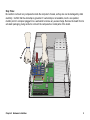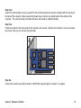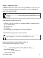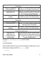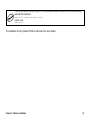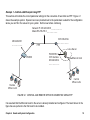
1
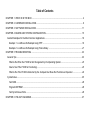
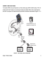
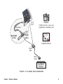
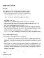
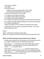
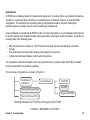
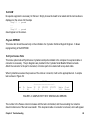
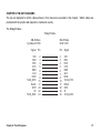
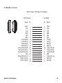
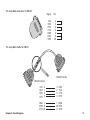
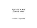
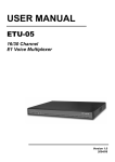
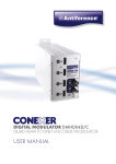
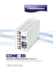
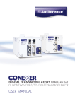
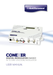
Cyclades-PC300
Installation Manual
Cyclades Corporation
Cyclades-PC300 Installation Manual
Version 2.1 – December 2000
Copyright (C) Cyclades Corporation, 2000
We believe the information in this manual is accurate and reliable. However, we assume no responsibility, financial
or otherwise, for any consequences of the use of this product or Installation Manual.
This manual is published by Cyclades Corporation, which reserves the right to make improvements or changes in
the products described in this manual as well as to revise this publication at any time and without notice to any
person of such revision or change. This manual corresponds to version 3.3.0 of the driver.
All brand and product names mentioned in this publication are trademarks or registered trademarks of their
respective holders.
FCC Warning Statement:
The Cyclades-PC300 has been tested and found to comply with the limits for Class A digital devices, pursuant to
Part 15 of the FCC rules. These limits are designed to provide reasonable protection against harmful interference
when the equipment is operated in a commercial environment. This equipment generates, uses and can radiate
radio frequency energy and, if not installed and used in accordance with the Installation Manual, may cause
harmful interference to radio communications. Operation of this equipment in a residential area is likely to cause
harmful interference in which case the user is required to correct the problem at his or her own expense.
Canadian DOC Notice:
The Cyclades-PC300 does not exceed the Class A limits for radio noise emissions from digital apparatus set out
in the Radio Interference Regulations of the Canadian Department of Communications.
Le Cyclades-PC300 n’émet pas de bruits radioélectriques dépassant les limites applicables aux appareils
numériques de la classe A prescrites dans le règlement sur le brouillage radioélectrique edicté par le Ministère
des Communications du Canada.
Table of Contents
CHAPTER 1 WHAT IS IN THE BOX .................................................................................................................... 4
CHAPTER 2 HARDWARE INSTALLATION.......................................................................................................... 8
CHAPTER 3 SOFTWARE INSTALLATION ........................................................................................................ 11
CHAPTER 4 BOARD AND SYSTEM CONFIGURATION .................................................................................. 15
Guided Examples for the Most Common Applications .................................................................................... 18
Example 1 A LAN-to-LAN Example Using PPP .......................................................................................... 19
Example 2 A LAN-to-LAN Example Using Frame Relay ............................................................................ 21
CHAPTER 5 TROUBLESHOOTING ................................................................................................................... 23
General Tips ..................................................................................................................................................... 23
What to Do When the PC300 is Not Recognized by the Operating System................................................ 23
How to Test if the PC300 is Functioning ...................................................................................................... 23
What to Do if the PC300 is Detected by the Computer but Does Not Function as Expected...................... 24
Cyctest/Linux .................................................................................................................................................... 25
Test RAM ...................................................................................................................................................... 26
Program EEPROM ....................................................................................................................................... 26
Test Synchronous Ports ............................................................................................................................... 26
CHAPTER 6 PIN-OUT DIAGRAMS.................................................................................................................... 27
CHAPTER 1 WHAT IS IN THE BOX
The Cyclades-PC300 can be purchased with one of three interface types--RSV/V.35 (RSV models), T1/E1 (TE
models) and X.21 (X21 models). One- and two-port varieties are available. What is in the box will depend on
the model. The purposes of the cables and how they should be connected are demonstrated in Figures 1.1-1.3.
Diskette CYCTEST
Driver
Pc300 nus Linux
For LiHardware Test
DB-25
Female
Flat Cable
Model With
2 Ports
//////////
DB-25
Female
DB-25
Male
Diskettes
PC300 Driver for Linux and
Cyctest/Linux Hardware Test
Installation Manual
Straight
Cable
DB-25
Male
DB-25 Female/
M.34 Male Converter
RS-232 Modem
with DB-25
Interface
V.35 DSU/CSU
with DB-25
Interface
FIGURE 1.1 RSV MODEL AND ACCESSORIES
Chapter 1 What is in the Box
4
The RSV model with 2 ports is accompanied by 4 cables, 2 of each type.
Diskette CYCTEST
Driver
Pc300 nus Linux
For LiHardware Test
Diskettes
PC300 Driver for Linux and
Cyctest/Linux Hardware Test
Model With Two Ports
RJ-48C
To T1 or E1
Connection
//////////
RJ-48C
Installation Manual
FIGURE 1.2 TE MODEL AND ACCESSORIES
The TE model with 2 ports is accompanied by 2 cables.
Chapter 1 What is in the Box
5
Diskette CYCTEST
Driver
Pc300 nus Linux
For LiHardware Test
DB-25
Female
Diskettes
PC300 Driver for Linux and
Cyctest/Linux Hardware Test
Flat Cable
Model With
2 Ports
//////////
DB-25
Female
Installation Manual
DB-25
Male
DB-15
Male
X.21 DSU/CSU
with DB-15
Interface
FIGURE 1.3 X21 MODEL AND ACCESSORIES
Chapter 1 What is in the Box
6
The X21 model with 2 ports is accompanied by 2 cables.
Two diskettes are provided: one contains the PC300 driver and its use is described in chapter 3; the other
contains Cyctest/Linux, a diagnostic tool, and its use is described in chapter 5.
Upgrades of Software and Manuals
This product is provided with a printed Installation Manual. Both this manual and software for the PC300 are
updated frequently, and the latest versions can be downloaded free from the Cyclades web site.
Chapter 1 What is in the Box
7
CHAPTER 2 HARDWARE INSTALLATION
The body carries static electricity and if the person installing the PC300 is not correctly grounded, the board
could suffer irreversible damage. Please follow the instructions outlined below carefully to avoid harming the
board.
Step One:
Unplug the computer and remove all cables connecting the computer to other devices.
Step Two:
Carry the computer to a workbench or table where an anti-static wrist-strap is available. If an anti-static wriststrap is not available (though it is highly recommended that one be used), continue on to the next step.
Remove the computer cover, exposing the boards inside. Attach the wrist-strap to your wrist.
.
Chapter 2 Hardware Installation
8
Step Three:
Be careful to not touch any components inside the computer’s chassis, as they also can be damaged by static
electricity. Confirm that the wrist-strap is grounded. If a wrist-strap is not available, touch a non-painted,
metallic part of a computer plugged in to a wall outlet to remove any excess charge. Remove the board from its
anti-static packaging, being careful to not touch the components or metal parts of the board.
.
Chapter 2 Hardware Installation
9
Step Four:
Insert the board carefully into any unused PCI slot so that the external connector is aligned with the opening in
the back of the computer. Make sure that the board does not touch any metallic parts of the interior of the
computer. The second bracket of models with two ports should be installed similarly.
Step Five:
Fasten the bracket to the back panel of the computer with a screw. Replace the computer’s cover and replace
the screws. Now you can remove the wrist-strap.
Step Six:
Connect the board to an external modem or DSU/CSU using the figure in chapter 1 as a guide.
Chapter 2 Hardware Installation
10
CHAPTER 3 SOFTWARE INSTALLATION
The PC300 driver diskette contains the files needed to run the Cyclades-PC300 in a Linux environment. This
driver should run without problems with all processors supported by Linux. However, Intel X86 is the only
platform officially supported by Cyclades.
This Installation manual assumes a minimum knowledge of the Linux operating system. Please
read the file /usr/src/linux/README before continuing, in order to understand the basics of kernel
compilation.
System Requirements for compatibility with the PC300:
• Linux kernel 2.0.34 or later; 2.2.15 or later; or 2.4.x (the last kernels tested for this release were versions
2.0.38, 2.2.16 and 2.4.0-test4).
• 486 processor or better.
• PCI bus support.
• Frame Relay support is only available for the 2.2.x series kernel, v.2.2.15 or later.
These instructions assume that your kernel source tree is /usr/src/linux.
Before installing the driver, please back up any critical information in your system.
Log in to the Linux computer as root. Place the diskette in the diskette drive.
Execute the following commands, beginning from any directory:
cd /tmp
tar xvf /dev/fd0 (this command copies the tar file from the diskette to the directory /tmp)
ls (to see the name of the tar file)
tar zxvf filename.tgz (to unzip and untar the file)
ls (to see the name of the directory)
Chapter 3 Software Installation
11
cd pc300-<version> (to go to the newly created directory)
NOTE: at this point you should read the file README included in the directory pc300-<version> to
learn about any changes implemented since this manual was produced.
sh install
(to run the install script)
This script will detect the system information (kernel version, current Cyclades-PC300 driver version, etc.) and
install the proper driver package files.
If an older version of the PC300 driver already exists, the files pc300.c, pc300.h, hd64572.h and falc-lh.h are
backed up with modified names in the same directory. If a newer version is already installed, the files will not be
updated with those of the older driver.
Configure the kernel by executing “make config” or “make menuconfig”:
Please note the following before beginning the kernel configuration. The only difference between
selecting Y/* or M is the following: Y/* causes the driver to be compiled as part of the kernel and is
activated every time the computer is booted; M creates the driver as a module, which can be
loaded or unloaded with a command without the need to reboot the computer.
The left column presents the commands and parameters that should be followed when using make config.
The right column provides the corresponding commands and parameters for make menuconfig.
cd /usr/src/linux
cd /usr/src/linux
make config
make menuconfig
For kernels 2.0.x:
CONFIG_PCI=Y (PCI support)
CONFIG_PC300=Y or M
select with '*' or 'm' the option "Cyclades-PC300 support" under
"Network device support"
CONFIG_KERNELD=Y to allow module
select with '*' the option "Kernel daemon support" under
autoloading.
"Loadable module support" to allow module autoloading.
Chapter 3 Software Installation
12
For kernels 2.2.x:
CONFIG_PCI=Y (PCI support) and
select with '*' or 'm' the option "Development and/or incomplete
CONFIG_EXPERIMENTAL=Y
code/drivers" in the "Code Maturity Level Options" section.
CONFIG_HDLC=Y or M,
select with '*' or 'm' the option "Generic HDLC driver" under
CONFIG_PC300=Y or M.
"Network device support", "Wan interfaces", and then select
with '*' or 'm' the option "Cyclades-PC300 support"
CONFIG_KMOD=Y to allow module
select with '*' the option "Kernel module loader" under
autoloading.
"Loadable module support" to allow module autoloading.
For kernels 2.4.x:
CONFIG_PCI=Y (PCI support)
CONFIG_PC300=Y or M
select with '*' or 'm' the option "Cyclades-PC300 support" under
"Network device support", "Wan interfaces"
CONFIG_KMOD=Y to allow module
select with '*' the option "Kernel module loader" under
autoloading.
"Loadable module support" to allow module autoloading.
For all kernels, if X.25 is to be used:
CONFIG_X25=Y or M,
to enable X.25 support, select with '*' the option "CycladesCONFIG_LAPB=Y or M,
PC300 X.25 support"; in the "Network Options" section select
and CONFIG_PC300_X25=Y
with "*" the option "CCITT X.25 Package Layer" and select with
enable X.25 support
"*" the option "LAPB Data Link Driver"
After leaving “make config” or “make menuconfig”, execute the command
make dep
to set up the dependencies.
Rebuild and install the PC300 driver using any common kernel compilation and installation method. One such
method is typing the following command from the /usr/src/linux directory:
make bzlilo
Chapter 3 Software Installation
13
If the PC300 driver or any other part of the Linux system was compiled as a module (M above),
execute the command
make bzlilo modules modules_install
instead of just
make bzlilo
The installation of the Cyclades-PC300 is continued in the next chapter.
Chapter 3 Software Installation
14
CHAPTER 4 BOARD AND SYSTEM CONFIGURATION
This chapter describes the configuration of the Cyclades-PC300. After the general instructions, guided
examples are provided to assist in parameter selection. Read the example closest to your application if in
doubt as to the best value for a parameter.
STEP ONE
Go to the directory /etc/cyclades/pc300 and type ls.
Each PC300 interface is assigned a device with the name hdlcN (where N is an integer). For the one-port
model, one ifcfg-hdlcN file must be created. For the two-port model, two files must be created. If this is the first
board being installed, the sample file ifcfg-hdlc0 will have already been placed in the directory above. When
additional boards/ports are installed, the ifcfg-hdlc0 file will not be overwritten (since it is being used by the first
interface installed), and additional files (ifcfg-hdlc1, etc.) must be created.
The notation hdlcN will be used throughout this manual to represent the file/port being manipulated and the
letter N should always be replaced by the appropriate integer.
When Frame Relay is used, an additional file with the name ifcfg-pvcN (where N is an integer) must
be created for each permanent virtual circuit (PVC).
STEP TWO
Create and/or modify the ifcfg-hdlcN file(s) for the ports of the PC300 installed. The parameters in the ifcfghdlcN file are as follows:
Parameter
DEVICE
BOARD
IPADDR
Description
Value
The device name assigned by the computer to hdlcN
this interface.
The board type.
pc300
The IP address of this interface.
Chapter 4 Board and System Configuration
15
NETMASK
NETWORK
The subnet mask of the IPADDR.
The network address of network where the
interface is installed.
BROADCAST
The broadcast address of the network.
POINTOPOINT The IP address of the device to which the
PC300 port is connected.
ONBOOT
Determines whether or not the interface is
activated when the computer is booted.
MEDIA
The hardware media used for this port
PROTO
The encapsulation protocol. The monitor
option causes the PC300 to emulate a line
analyzer--it does not process received
packets before sending them on and
cannot send packets
DCE
Applies when frame relay is used.
Determines if the interface will be a DCE or
a DTE. If the PC300 is connected to a
public frame relay network, it will be a DTE.
CLOCK
The clock mode or clock rate in bps.
LCODE
FRAME
LBO
RX_SENS
ACTIVE_CH
yes or no
rs232, v35, x21, t1 or e1
x25, ppp, cisco (for Cisco HDLC), fr_ansi (for
ANSI frame relay), fr_ccitt (for CCITT frame
relay) and monitor (for passive mode).
yes or no
ext (for external clock) or a number
representing the clock speed (which implies an
internal clock). For TE boards only, int (for
internal clock) should be used when applicable.
For T1/E1 channels only. The line code.
T1: ami, b8zs, or nrz; E1: ami, hdb3, or nrz.
For T1/E1 channels only. The frame mode. T1: esf or d4; E1 crc4, non-crc4 or unframed.
For T1 channels only.
0, 7.5, 15, or 22.5.
For T1/E1 channels only. The receiver
sh (for short haul) or lh (for long haul)
sensitivity.
For T1/E1 channels only. The active 64Kb all (for full links), x,a-b,w etc. (where the letters
channels.
are numbers; to specify the channels x and w
and the range of channels a-b, inclusive for
fractional links)
Chapter 4 Board and System Configuration
16
When frame relay is used, create and/or modify the ifcfg-pvcN file(s) for the PVC to be used with
the PC300 installed. The parameters in the ifcfg-pvcN file are as follows:
Parameter
DEVICE
MASTERDEV
DLCI
IPADDR
POINTOPOINT
ONBOOT
Description
The device name assigned by the computer to
this PVC.
The interface with which this PVC is
associated
The DLC number assigned to this PVC
The local IP address of this PVC.
The remote IP address of the PVC.
Determines whether or not the interface is
activated when the computer is booted.
Value
pvcN
hdlcN (this N is not necessarily the same
as the N in the device name pvcN above)
yes or no
STEP THREE
If the driver was installed as a module (see explanation in chapter 3), the file /etc/conf.modules
(or /etc/modules.conf, depending on the distribution) must be modified. Add the line
alias hdlcN pc300
anywhere in the file.
STEP FOUR
After creating and editing the ifcfg-hdlcN file(s) for the port(s),
execute the command
pc300up hdlcN
to activate each interface.
The following command can be executed to deactivate the interface:
pc300down hdlcN
Chapter 4 Board and System Configuration
17
When frame relay is used, after creating and editing the ifcfg-pvcN file(s) for the PVC(s), execute the
command pc300up pvcN to activate each PVC.
The command ifconfig (without parameters) will show the status of all activated ports. Each hdlcN
device should be listed separately (one per port).
STEP FIVE
For the Linux to function as a router, routing must be enabled. This can be done by executing the following
command:
echo 1 > /proc/sys/net/ipv4/ip_forward
To make this effective every time the system is booted, include the line above in one of the scripts run during
initialization (in /etc/rc.d). Some distributions provide a configuration interface to set this parameter (such as
linuxconf.) Refer to the Linux distribution documentation.
Reboot the system and inspect the boot messages. The driver should report the PC300 boards detected.
Cyclades-PC300 driver <version> <date> built <date>
hdlc0: PC300/RSV #1, 256KB of RAM at 0xMMMM, IRQn, channel 1.
hdlc1: PC300/RSV #2, 256KB of RAM at 0xMMMM, IRQn, channel 1.
etc.
At this point the installation of the board is complete.
Guided Examples for the Most Common Applications
This chapter provides detailed examples that can be used as models for similar applications. Turn to the
example that is closest to your application, read the explanations, and edit the configuration file with
parameters appropriate to your system.
Chapter 4 Board and System Configuration
18
Example 1 A LAN-to-LAN Example Using PPP
This section will indicate the correct parameter settings for the connection of two LANs via PPP. Figure 4.1
shows the example system. Spaces have been provided next to the parameters needed for the configuration
where you can fill in the values for your system. Do this now before continuing.
Network IP: 200.240.230.0 _ _ _ _ _ _ _ _
Mask:255.255.255.0 _ _ _ _ _ _ _ _
200.240.230.1
________
PPP
V.35 DSU/CSU
________
Linux Server
PR2000
PC300 RSV
V.35 Interface
200.240.230.2
________
Ethernet Card
Central
Office’s LAN
Remote
Office’s LAN
FIGURE 4.1 CENTRAL AND REMOTE OFFICES CONNECTED USING PPP
It is assumed that the Ethernet board in the server is already installed and configured. The board shown in the
figure has one port and is the first board to be installed.
Chapter 4 Board and System Configuration
19
The file ifcfg-hdlcN file for the example is:
DEVICE=hdlc0
BOARD=pc300
IPADDR=200.240.230.2
NETMASK=255.255.255.0
NETWORK=200.240.230.0
BROADCAST=200.240.230.255
POINTOPOINT=200.240.230.1
ONBOOT=yes
MEDIA=v35
PROTO=ppp
CLOCK=ext
The clock is external because it is generated by the DSU/CSU.
A default gateway should have been set up, either using linuxconf or an alternative method. The
command netstat -rn shows all routes in the routing table.
At this point, the PC300 should be performing router functions. Use the method described in chapter 5 , “How
to Test if the PC300 is Functioning”, to confirm that the installation and configuration have been performed
correctly.
Chapter 4 Board and System Configuration
20
Example 2 A LAN-to-LAN Example Using Frame Relay
This section will indicate the configuration settings for the connection of two LANs via Frame Relay. Figure 4.2
shows the example system. Spaces have been provided next to the parameters needed for the configuration
where you can fill in the values for your system. Do this now before continuing.
16
Public
Frame Relay
Network
200.240.230.1
________
PR2000
Remote
Office’s LAN
V.35 DSU/CSU
________
Linux Server
PC300 RSV
V.35 Interface
200.240.230.2
________
Ethernet Card
Central
Office's LAN
FIGURE 4.2 CENTRAL AND REMOTE OFFICES CONNECTED USING FRAME RELAY
It is assumed that the Ethernet board in the server is already installed and configured. The board shown in the
figure has one port and is the first board to be installed.
Chapter 4 Board and System Configuration
21
The ifcfg-hdlcN file for the example is:
DEVICE=hdlc0
BOARD=pc300
ONBOOT=yes
MEDIA=v35
PROTO=fr_ansi or fr_ccitt
DCE=no
CLOCK=ext
The ifcfg-pvcN file for the example is:
DEVICE=pvc0
MASTERDEV=hdlc0
DLCI=16
IPADDR=200.240.230.2
POINTOPOINT=200.240.230.1
ONBOOT=yes
A default gateway should have been set up, either using linuxconf or an alternative method. The
command netstat -rn shows all routes in the routing table.
At this point, the PC300 should be performing router functions. Use the method described in chapter 5 , “How
to Test if the PC300 is Functioning”, to confirm that the installation and configuration have been performed
correctly.
Chapter 4 Board and System Configuration
22
CHAPTER 5 TROUBLESHOOTING
General Tips
What to Do When the PC300 is Not Recognized by the Operating System
• Does the operating system detect the PC300 on boot? A message similar to
Cyclades-PC300 driver <version> <date> built <date>
hdlc0: PC300/RSV #1, 256KB of RAM at 0xMMMM, IRQn, channel 1.
hdlc1: PC300/RSV #2, 256KB of RAM at 0xMMMM, IRQn, channel 1.
etc.
•
•
•
•
should appear on boot. If not,
Is the board properly installed (physically)? Check the connections inside the computer.
Does your Linux operating system meet the requirements outlined at the beginning of chapter 3? The
kernel version can be discovered by typing the command uname -r.
The steps in chapter 4 related to the device files should be reviewed and the configuration files checked.
Check the configurations modified using “make config” or “make menuconfig” (details supplied in chapter
3). If they are incorrect, execute the commands make dep and then make bzlilo modules
modules_install again to rebuild the kernel. Reboot the computer and see if the boards are detected.
How to Test if the PC300 is Functioning
• The simplest way to test a WAN connection is by pinging. Type ping <IP address of device to be
pinged>. If a response is not received from the remote machine there is probably a problem with the link.
Make sure the remote machine is up by accessing it from another computer before following the directions
below.
• When the PC300 driver is installed, a utility called pc300util is placed in the /usr/local/sbin directory. It can
be used to detect problems between the PC300 and the operating system. This utility provides statistics,
the line status, line traces, loop-back tests for T1/E1 lines, and a listing of the configuration of the board. It
accepts the following options:
pc300util [-csStlrpUDP] [-d hdlcN] [-f file_name]
where
Chapter 5 Troubleshooting
23
-c: Shows the board´s configuration
-s: Shows statistics
-S: Shows the status of the link
For RSV/X.21 boards, shows the signals DCD, DSR, CTS, RTS, and DTR
For TE boards, shows link alarms and if the line is synchronized or not.
-t: Starts a line trace which continues until CTRL-C is pressed.
-l: For TE boards only, sets the interface to local loop-back.
-r: For TE boards only, sets the interface to remote loop-back.
-p: For TE boards only, sets the interface to payload loop.
-U: For TE boards only, sends signal (loop UP) indicating that the remote interface should set itself to loop.
-D: For TE boards only, send signal (loop DOWN) indicating that the remote interface should stop looping.
-P: For TE boards only, starts a pattern test.
-d: Selects the device (hdlcN). If the name of the interface is not supplied, hdlc0 will be assumed.
-f: Defines the file to which the trace, statistics or status information will be written. If not included, the
information will appear on the screen.
Examples:
pc300util -c -d hdlc1 will show the configuration of the hdlc1 interface
pc300util -t -f trc_hdlc0 will begin a line trace for the hdlc0 interface and write the results to the file trc_hdlc0
What to Do if the PC300 is Detected by the Computer but Does Not Function as Expected.
• Is the cable properly connected and is the correct cable being used? Check the physical connection and
refer to chapter 1 for descriptions and uses of the cables that accompany the product.
• Type the command ifconfig. Do the devices set up for the board in chapter 4 appear? If you set the
parameter ONBOOT to no in the configuration file, you will need to activate the interface with the
command ifup hdlcN, also described in chapter 4.
• Type the command cat /proc/sys/net/ipv4/ip_forward. If the result is 0, routing was not set up
correctly. Return to the instructions for linuxconf in chapter 4, step 5, and confirm that routing is enabled.
• Type the command netstat -rn to see the routing table. Have you defined a default gateway and/or have
a route that includes the remote device you are trying to reach?
Chapter 5 Troubleshooting
24
Cyctest/Linux
All PC300s are completely tested at Cyclades before being sold. It is unlikely that a new board will be defective.
Therefore, if a new board does not function, it is probably due to a hardware conflict or an incorrect BIOS
configuration. The board and Linux operating system configurations should be checked, following the
instructions given in chapters 3 and 4, before considering a hardware test.
A second diskette is included with all PC300 models. It contains Cyctest/Linux, a set of hardware tests than can
be used to determine if a hardware problem really exists before returning the board to Cyclades. Cyctest/Linux
is usually used in the following cases:
• After the instructions in chapters 3, 4 and 5 have been followed, but the board still does not function
correctly.
• If the board stops functioning after having worked properly for some time.
• To detect and eliminate hardware conflicts with other devices.
The Cyctest/Linux diskette is bootable, and to use Cyctest/Linux the computer where the PC300 is installed
must be booted with the Cyctest/Linux diskette.
The main menu of Cyctest/Linux is shown in Figure 5.1.
Single Board
Operations
Choose Board
Test Asynchronous Ports
Test Synchronous Ports
Test RAM
Test IRQ
Program EEPROM
Shading Indicates Test That Does Not Apply to the PC300
FIGURE 5.1 MAIN MENU OF CYCTEST
Chapter 5 Troubleshooting
25
Test RAM
No special equipment is necessary for this test. Simply choose the board to be tested and the test results are
displayed on the screen. All the steps
Step 1.1 ... passed
...
...
Step 4.2 ... passed
should appear on the screen.
Program EEPROM
This menu item should be used only on the indication of a Cyclades Technical Support Engineer. It allows
reprogramming of the EEPROM.
Test Synchronous Ports
This menu option tests all Synchronous Cyclades board ports installed in the computer. A loop-back cable or
connector is necessary. The pin diagrams are provided in the Cyclades Serial Boards Reference Guide.
Attach the connector to the port to be tested, or link two ports to be tested with a loop-back cable.
When Cyctest/Linux senses the presence of the cable or connector, it will run the appropriate test. A sample
test is shown in Figure 5.2
Brd
1
Ch
1
Passes
68
ERRORS
<----------------------->
TX
RX
DTR/DCD
RTS/CTS
0
0
0
0
Media
V.35
Clock
Master
FIGURE 5.2 SAMPLE PORT TEST SHOWING NO ERRORS.
The number in the Passes column increases until the test is terminated, and the succeeding four columns
should contain zeros if the test is successful. If the loop-back cable or connector is removed, errors will appear.
Chapter 5 Troubleshooting
26
CHAPTER 6 PIN-OUT DIAGRAMS
The pin-out diagrams for all the cables shown in this manual are provided in this chapter. Which cables are
provided with the product will depend on model and country.
The Straight Cable:
Straight Cable
DB-25 Male
Cyclades-PC300
Chapter 6 Pinout Diagrams
DB-25 Male
DCE / DTE
Signal
Pin
Pin
Signal
TxD
RxD
RTS
CTS
DSR
Gnd
DCD
TxClk_DTE
RxClk
DTR
RI
TxClk_DCE
2
3
4
5
6
7
8
15
17
20
22
24
2
3
4
5
6
7
8
15
17
20
22
24
TxD
RxD
RTS
CTS
DSR
Gnd
DCD
TxClk_DTE
RxClk
DTR
RI
TxClk_DCE
27
The Router MD/V35 Cable:
DB-25 Male
Cyclades-PC300
D/
V.
M
DB-25 Male
35
Rou
ter
DB-25 Male
Chapter 6 Pinout Diagrams
DB-25 Male
Telebrás Standard
Signal
Pin
Pin
PGnd
RTS
CTS
DSR
Gnd
DCD
TxD/V.35 (B)
TxD/V.35 (A)
RxD/V.35 (B)
RxD/V.35 (A)
TxClk_DTE/V.35 (B)
TxClk_DTE/V.35 (A)
TxClk_DCE/V.35 (B)
TxClk_DCE/V.35 (A)
RxClk/V.35 (A)
RxClk/V.35 (B)
1
4
5
6
7
8
11
12
13
14
16
18
19
21
23
25
1
5
7
9
13
10
15
2
17
4
16
3
24
11
6
19
- A
- C
- D
- E
- B
- F
- S
- P
- T
- R
- AA
- Y
- W
- U
- V
- X
28
The DB-25/M.34 Converter:
DB-25 Female - M.34 Male (V.35) Adapter
DB-25 Female
Chapter 6 Pinout Diagrams
M.34 Male
Signal
Pin
Pin
Signal
PGnd
RTS
CTS
DSR
Gnd
DCD
TxD/V.35 (B)
TxD/V.35 (A)
RxD/V.35 (B)
RxD/V.35 (A)
TxClk_DTE/V.35 (B)
TxClk_DTE/V.35 (A)
TxClk_DCE/V.35 (B)
DTR
TxClk_DCE/V.35 (A)
RxClk V.35 (A)
RxClk V.35 (B)
1
4
5
6
7
8
11
12
13
14
16
18
19
20
21
23
25
A
C
D
E
B
F
S
P
T
R
AA
Y
W
H
U
V
X
PGnd
RTS
CTS
DSR
Gnd
DCD
TxD (B)
TxD (A)
RxD (B)
RxD (A)
TxClk_DTE (B)
TxClk_DTE (A)
TxClk_DCE (B)
DTR
TxClk_DCE (A)
RxClk (A)
RxClk (B)
29
The T1/E1 Cable:
Cyclades-PC300
RJ-48C
T1/E1 Terminal Adapter
RJ-48C
Pin Signal
Signal Pin
RxTip
RxRing
N.C.
TxTip
TxRing
N.C.
N.C.
N.C.
1
2
3
4
5
6
7
8
1
2
3
4
5
6
7
8
RxTip
RxRing
N.C.
TxTip
TxRing
N.C.
N.C.
N.C.
The DB-25/DB-15 Cable for X.21:
Cyclades-PC300
(DB-25)
Chapter 6 Pinout Diagrams
X.21 Equipment
(DB-15)
Signal
Pin
Pin
Signal
CGND
CLKINDRxDGND
CTLTxDCLK+
IND+
RxD+
CTL+
TxD+
1
2
4
6
7
9
11
15
17
19
22
24
1
6
5
4
8
3
2
13
12
11
10
9
CGND
CLKINDRxDGND
CTLTxDCLK+
IND+
RxD+
CTL+
TxD+
30
The Loop-Back Connector for DB-25:
T
E
T
S
E
Signal
Pin
TxD
RxD
RTS
CTS
DSR
DCD
DTR
2
3
4
5
6
8
20
The Loop-Back Cable for DB-25:
DB-25 Female
DB-25 Female
TxD
RxD
RTS
CTS
2
3
4
5
GND 7
DCD 8
DTR 20
Chapter 6 Pinout Diagrams
3
2
5
4
RxD
TxD
CTS
RTS
7 GND
20 DTR
8 DCD
31
Cyclades Corporation
41829 Albrae Street
Fremont, CA 94538 - USA
Phone: (510) 770-9727
Fax: (510) 770-0355
www.cyclades.com
Cyclades Europe
Kenzestrasse 5-7
D-85737 Ismaning - Germany
Phone: +49-89-96-22-84-55
Fax: +49-89-96-22-84-39
www.cyclades.de
Cyclades South America
Av. Santa Catarina, 155
São Paulo, SP, Brazil
CEP: 04635-000
Phone: (11) 5033-3333
www.cyclades.com.br