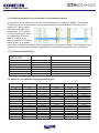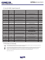
1
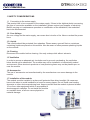
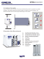
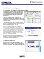
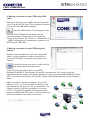
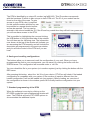
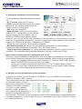
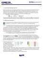
DIGITAL TRANSMODULATORS DTM6x4•3x2
QUAD& TWIN DVB-S/S2 - DVB-T TRANSMODULATOR
USER MANUAL
DTM6x4•3X2
Congratulations on your purchase of your Digital Transmodulator (DTM)
This ‘state of the art’ product, is a digital transmodulator and performs the following
functions within the system:
a) It receives the satellite programmes from 2 (DTM3x2) or 4 (DTM6x4) satellite frequencies.
b) The programmes of the satellite inputs are re-multiplexed together with programmes from off air Freeview, additional DTM units and/or Conexer digital encoder modulators.
c) An extra USB input allows connection of a USB stick containing ‘.ts files’. These ‘.ts files’ can be used for broadcast purposes by creating its own programme or replacing an existing programme based on a time schedule.
d) An ethernet connection allows connection to the web for re-configuration/
monitoring.
CONTENTS
1
Safety considerationspage 3
1.8 Location of the modulepage 4
2
Description of the different elements
page 4
3
Installation of operating softwarepage 5
3.1
Downloading & installing softwarepage 5
3.2
Launching the DTViFacepage 5
4
Making connection to your DTM using USB cable
page 6
5
Making connection to your DTM using the internet
page 6
6
Saving and recalling configurations
page 7
7
Standard programming of the DTM
page 7
8
Setting the parameters of the modulator
page 8
9
Adding services to the modulator
page 8
10
Using High definition HD LCN
page 9
11
Additional informationpage 9
12
Relative bandwidth of a programme page 10
13
Technical Specifications
page 10
14
Appendix A Constellation & max bit rates
page 10
15
Appendix B ONID original network ID
page 11
16
Declaration of Conformitypage 11
2
DTM6x4•3X2
1 SAFETY CONSIDERATIONS
1.1 Connecting to the mains supply
This product has to be connected to the mains supply. If there is the slightest doubt concerning
the type of connection available on the installation, please contact your supplier of electricity.
Before carrying out maintenance operation or modification of the installation, the modulator
has to be disconnected.
1.2 Over Voltage
An over voltage on the mains supply, can cause short circuits or fire. Never overload the power
lines.
1.3 Liquids
This module should be protected from splashes. Please assure yourself that no containers
containing liquids are placed on this module. Also be aware of other persons splashing liquids
on the module.
1.4 Cleaning
Disconnect the module before cleaning. Use only a damp cloth without solvents.
1.5 Ventilation
In order to assure an adequate air circulation and to prevent overheating, the ventilation
holes should not be obstructed. The module may not be installed in a hermetically sealed
environment. Other electronic products or heat producing items may not be placed upon or
near the module.
1.6 Accessories
The use of accessories not manufactured by the manufacturer can cause damage to the
module.
1.7 Installation of the module
The module must be installed in a place well protected from direct sunlight. All measures
have to be taken to avoid installation in humid or sunny places. Do not install near heating
elements or other devices producing heat. Assure yourself that the module is placed at least
10 cm from other equipment which is susceptible to
electromagnetic radiation. Do not install the module
on unstable items, a fall can cause physical or
material damage.
3
DTM6x4•3X2
1.8 Location of the module
Leave a minimum pace of at least 15cm above and below the product to guarantee an optimal
ventilation. The module should be mounted to assure a maximum natural ventilation. The
module should be fixed to a wall using the wall fixings on the module.
15cm
15cm
2 Description of the different elements
C6
C12
C5
C11
C4
C10
C3
C9
C2
C8
C1
C7
C1
Input LNB A (first module RR5 = input C)
C2
Output LNB A (first module RR5 = input C)
C3
Input LNB B (second module RR5 = input C)
C4
Input LNB B (second module RR5 = input C)
C5
USB input ( for reading.ts files (first RR5)
C6 Ethernet connection (RJ45) (first RR5)
C7
Input LNB A
C8
Output LNB A
C9
Input LNB B
C10 Output LNB B
C11
USB input ( for reading .ts files (first RR5)
C12 Ethernet connection (RJ45) (first RR5)
C13 DVBT input (bypass)
C14 DVBT output
C15 Power input 230v
C16 USB input (PC
C15
connection)
C14
C13
C16
4
DTM6x4•3X2
3 Installation of the operating software
3.1 Downloading and installing the programming software
Programming is achieved via the DVTiFace which
can be downloaded for free from www.antiference.
co.uk/conexer-dvd-s2-dvb-t-transmodulators and
clicking the downloads tab on the transmoduator
product page.
The DVTiFace is the control software for the
Antiference DTM range and can also be used for the
configuration of the DMSD and DMHD A/V and HDMI
modulator range.
This section will explain how to install the software
on your PC making a connection via USB or over the
web, saving and re-opening ‘.dtc’ files
The DVTiFace is compatible with Windows XP, 7
& 8 and can be downloaded at www.antiference.
co.uk/conexer-dvb-s2-dvb-t-transmodulators and by
clicking on the ‘downloads’ tab. Locate the zip file
and download. The software can be installed to your
machine using wizard and following instructions.
Once the installation is complete you can connect
your PC to the Conexer product.
We are constantly improving our software so we
advise you to regularly check our website to ensure
you have the latest release installed.
3.2 Launching the DTViFace
Double click the DVTiFace icon installed on your
desktop or find DVTiFace in the list of programs and
launch the programme. The following screen will open :
5
DTM6x4•3X2
4. Making connection to your DTM using USB
cable
Make sure that there is an USB connection between
your PC and the DTM (the DTM or compact headend
comes with the USB cable supplied).
Press the USB button in the left upper corner
If all OK, the DTVRack should appear with all
modules installed. Please note, in the upper left
corner of the window : DTViFace 7.4 - Antiference (c)
- (USB), indicating that a connection is made to your
DTM using a USB cable.
5. Making connection to your DTM using the
internet
Besides local connections to your rack using USB
cable, it is also possible to make a connection to
a remote DTM which is properly connected to the
internet.
In order to access your rack or racks over the
web, please press the web button.
In the first step you have to fill in your USER
Software ID and KEY. This software ID and KEY are personal. So in order to get this
information, please contact your dealer, distributor to get your personalised Software ID and
KEY. If you have received your ID and KEY, please input these parameters in the indicated
fields.
Make sure that for the server address, Port, the IP
address 176.31.117.132 and 6666 are filled in. If all
parameters are OK (and your PC is connected to the
internet), then you will be connected to our server
176.31.117.132 which handles all communications
between USERS and DTM units. In the list below, you
will see all modules connected to the server.
6
DTM6x4•3X2
The DTM is identified by a unique ID number (eg fa001169). This ID number corresponds
with the hardware ID which is also unique to each DTM unit. The ID of your module can be
found on the side of the case. To gain
access to your DTM a key is required
for this specific module and this key can
be provided on request should remote
access be required. The key can be
entered in the column beside the ID. If the ID and key match then they will both turn green and
you will now have access to the DTM.
This is possible by highlighting the row and clicking
the USB button on the right hand side of the window.
You will then see the following view. The information
now shown at the top of the window will indicate you
are accessing the DTM remotely and will include the
description as programmed in the previous window
and you will have control of the DTM as if you are
local.
6. Saving and recalling configurations
The buttons allow you to save and recall the configuration of your rack. When you have
programmed the rack to your requirements, you can save it by clicking the button with the
GREEN arrow. The configuration will be saved under a ‘.dtc’ file.
You can reload this file in your system (or in another system) just by clicking the button with the
RED arrow.
After pressing this button, select the ‘.dtc’ file of your choice. DTViFace will check if the loaded
configuration is compatible with your system (if the number of inputs is different from the
loaded configuration it will not be loaded into your system). Before loading, an overview of
the configuration is shown in the window, press OK to finally load the configuration into your
system.
7. Standard programming of the DTM
When the software is running by clicking on the
DTVRR5 symbol the main programming window will
open. The DTM6x4 will have 2 DTVRR5 options to
accommodate the additional inputs.
7
DTM6x4•3X2
8. Setting the parameters of the modulator
For the modulator following parameters can be
set:
• N.I.T Version: enter the NIT version.
• ONID: enter the decimal code for the Original
Network ID. The original network ID is the
country where you are located.
• NID: enter the network ID.
• Network Name: enter the network name.
Under the N.I.T. parameters you will find the
output frequency of the modulator. As the
DTM6x4 & DTM3x2 have adjacent output
channels, you can only set the output frequency of the first channel. The frequency of the other
channels is automatically adjusted, so you can not change the output frequency of the second
channel (for DTM3x2) or the other 3 channels (for DTM6x4).
• T.S. Id: for each channel a T.S.Id should be assigned.
• Modulation parameters: you can set the modulation parameters for the modulator.
Please select the constellation, Bandwidth, F.E.C and Guard Interval.
• Output level of the modulator: an internal attenuator allows to lower the output level of the
modulator. The attenuator can be adjusted between 0 dB (max. output) and -20 dB.
Some notes on setting the N.I.T parameters and T.S. Id.:
When you make a headend you will probably have more than one modulator in your system. In
order to keep consistency throughout your complete headend, please follow these guidelines :
a) For your complete headend make sure that the N.I.T. (version / ONID / NID / Network Name) are IDENTICAL throughout the entire system.
b) For your complete headend make sure that all T.S. Id. (Transport Stream ID) are UNIQUE. Every output channel should have a unique ID in the system. Make sure that an T.S.Id. does not appear more than once in the system.
9. Adding services (programmes) to the modulator:
In the list of programs, you will find two (for DTM3x2) or four (for DTM6x4) columns with a
GREEN + symbol or RED - symbol.
The columns indicate the output channels of the modulator (column 1 is first channel, column
2 is second channel (column 3
and column 4 are third and fourth
channel for DTM6x4 modulator).
If a green + symbol appears
besides a certain programme,
this means that this programme is
added to that specific channel in
the modulator. The status can be changed by double-clicking the activation symbol besides the
requested programme. In the far right columns you can add a LCN number or HDLCN number
for channel numbering.
8
DTM6x4•3X2
10. Using High Definition HD LCN
In some systems you may want to broadcast a version of a programme in Standard Definition
(SD) at the same time as High Definition (HD). With HD LCN numbering, you can force HD
Television sets to follow the HD LCN numbering and SD Television sets to follow the LCN
numbering for those programs which are transmitted in duplicate. For example: You want to
broadcast a BBC television programme in SD version as well as in HD.
Application of HD LCN would be:
BBC1 LCN: 5 HDLCN: 55
BBC1HD LCN: 55 HDLCN: 5
Television sets with the HD tuner will now put BBC1 HD on number 5 and BBC1 on channel 55
Television sets without the HD tuner will now put BBC1 HD on number 55 and BBC1 on channel 5
11. Additional information
In the window of the DTM6x4/ DTM3x2 modulator you will find some useful additional
information. To the left of N.I.T information, you will find a ‘terrestrial symbol’.
The number under this symbol gives you the total occupied bandwidth of the modulator.
This number should not exceed the maximum available bandwidth of the modulator.
The maximum available bandwidth is calculated on the maximum available bandwidth
per channel x the number of channels. The maximum available bandwidth per channel is
depending on the modulation parameters (Constellation / Bandwidth / F.EC./Guard Interval).
You will find an overview of the maximum available bandwidth in the ‘functions of the
modulation parameters’ later in this manual.
As an example for a DTM6x4 modulator, the maximum available bandwidth is:
4 x 31.6 Mbit/s = approx. 125 Mbit/s. For a DTM3x2, this is half (2 x 31.6).
The occupied bandwidth of each channel in the
modulator is showed by bar graphs in the modulator
window. The occupied bandwidth will increase as the
number of programmes added to that channel is increased. It also depends on the bandwidth
of each individual programme. Please check not to overload a channel as this will lead to
errors in the programmes.
Please note that when no
services (programmes)
are added to an output
channel, the channel will be
not active. This also means
that you can choose the
DTM6x4 to act as a single, twin, triple or quad modulator, or for a DTM3x2 to use it as a single
channel modulator. If you change satellite parameters, the previously defined services for the
modulator will appear as question marks in the list. (see figure below). You can remove these
services by double clicking the activation button.
Note that services preceded with a ‘?’ should not be in the list.
9
DTM6x4•3X2
12. Relative bandwidth of a programme in the transport stream
In the bottom of the window you will find a bar divided into a number of panels. The number
of panels is equal to the number of programmes added to the modulator. The width of the
panels is in direct relation
with the bandwidth of the
programme. For example,
in the window below, when
on programme ‘Extreme
Sports’, a panel in the
bottom turns blue This blue
panel gives you a relative
idea of the occupied bandwidth of this programme in the transport stream. This information can
be helpful in assigning the different programmes to the different channels on the modulator.
13. Technical Specifications
DVBT output (adjacent)
(DTM6x4 = 2 channels)
(DTM3x2 = 4 channels)
Attenuation
> 95 dBμV
Attenuation
0 - 20 dB
Insertion loss
< 2 dB
Output frequency
47-862 MHz
Constellation
QPSK/16QAM/64QAM
FEC
1/2, 2/3, 3/4, 5/9, 7/8
Guard interval
1/4, 1/8, 1/16, 1/32
Mode
2K
14. Annex A: Constellation and maximum bit rate
Modulation
Code Rate
Guard 1/4
Mb/s
Mb/s
Mb/s
Mb/s
QPSK
1/2
4.976471
5.529412
5.854671
6.032086
2/3
6.635294
7.372549
7.806228
8.042781
3/4
7.464706
8.294118
8.782007
9.048128
5/6
8.294118
9.215686
9.757785
10.05348
7/8
8.708824
9.676471
10.24567
10.55617
1/2
9.952941
11.05882
11.709341
12.06417
2/3
13.27059
14.74510
15.61246
16.08556
3/4
14.92941
16.58824
17.56401
18.09626
5/6
16.58824
18.43137
19.51557
20.10695
7/8
17.41765
19.35294
20.49135
21.11230
1/2
14.92941
16.58824
17.56401
18.0926
2/3
19.90588
22.11765
23.41869
24.12834
3/4
22.39412
24.88235
26.34602
27.14439
5/6
24.88235
27.64706
29.27336
30.16043
7/8
26.12647
29.02941
29.27336
31.66845
16 QAM
64 QAM
Guard 1/8
10
Guard 1/16
Guard 1/32
DTM6x4•3X2
15. Annex B: ONID: Original Network ID
Original Network ID
Original Network ID
Range
Original_Network_Name
Start (HEX)
Original_Network_Operator
End (HEX)
…..
0x2024
0x2024
Australian Digital Terrestrial Television
Australian Broadcasting Authority
0x2028
0x2028
Austrian Digital Terrestrial Television
ORS - Austrian Broadcasting Services
8232
0x2038
0x2038
Belgian Digital Terrestrial Television
BIPT
8248
0x209E
0x209E
Taiwanese Digital Terrestrial Television
Directorate General of Telecommunications
0x20CB
0x20CB
Czech Republic Digital Terrestrial Television
Czech Digital Group
0x20D0
0x20D0
Danish Digital Terrestrial Television
National Telecom Agency Denmark
0x20E9
0x20E9
Estonian Digital Terrestrial Television
Estonian National Communications Board
0x20F6
0x20F6
Finnish Digital Terrestrial Television
Telecommunicatoins Administratoin Centre, Finland
0x20FA
0x20FA
French Digital Terrestrial Television
Conseil Superieur de l'AudioVisuel
8442
0x2114
0x2114
German Digital Terrestrial Television
IRT on behalf of the German DVB-T broadcasts
8468
0x2168
0x2168
Digital Terrestrial Network of Indonesia
Ministry of Communication and Information Technology of
the Republic of Indonesia
0x2174
0x2174
Irish Digital Terrestrial Television
Irish Telecommunications Regulator
0x2178
0x2178
Israeli Digital Terrestrial Television
BEZEQ (The Israel Telecommunication Corp Ltd .)
0x217C
0x217C
Italian Digital Terrestrial Television
0x21AC
0x21AC
DTT - Latvian Digital Terrestrial Television
8572
0x2210
0x2210
Netherlands Digital Terrestrial Television
Nozema
0x222A
0x222A
DTT - New Zealand Digial Terrestrial Television
TVNZ on behalf of Freeview New Zealand
0x2242
0x2242
Norwegian Digital Terrestrial Television
Norwegian Regulator
0x2260
0x2260
DTT - Philippines Digital Terrestrial Television
NTA (porivionally ABS-CBN)
0x2268
0x2268
DTT Poland
0x22BE
0x22BE
Singapore Digital Terrestrial Television
8438
8720
Singapore Broadcasting Authority
0x22BF
0x22BF
0x22C1
0x22C1
DTT - Slovenian Digital Terrestrial Television
APEK
0x22C6
0x22C6
DTT - South African Digital Terrestrial Television
South African Broadcasting Corporation Ltd. (SABC), pending
formation of "DZONGA"
0x22C7
0x22C7
DTT- Hungarian Digital Terrestrial Television
National Communications Authority, Hungary
0x22C8
0x22C8
DTT- Portugal Digital Terrestrial Television
ANACOM- National Communications Authority
0x22D4
0x22D4
Spanish Digital Terrestrial Television
“Spanish Broadcasting Regulator
0x22F1
0x22F1
Swedish Digital Terrestrial Television
“Swedish Broadcasting Regulator ”
8945
0x22F4
0x22F4
Swiss Digital Terrestrial Television
OFCOM
8948
0x233A
0x233A
UK Digital Terrestrial Television
Independent Television Commission
8916
…..
16. Declaration of Conformity:
We, ANTIFERENCE LIMITED herewith declare that the modulator CONEXER DTM6x4 complies with all essential requirements
and any other applicable conditions set forth on directive 1999/05/CE.
According to the WEEE (Waste Electrical and Electronic Equipment) EU Directive, do not dispose of this product as household
waste or commercial waste. Waste electrical and electronic equipment should be appropriately collected and recycled as
required by practices established for your country. For information on recycling of this product, please contact your local
authorities, your household waste disposal service or the shop where you purchased the product.
Date of issue: March 2015
11
www.antiference.co.uk