1
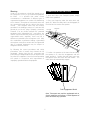
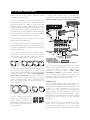
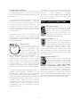
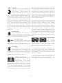
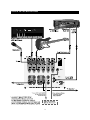
PORTABLE
SOUND SYSTEMS
From Fender Pro Audio
Owner's Manual for
Passport
P/N 051854
REV B
Fender Musical Instruments
7975 North Hayden Road, Scottsdale, Arizona 85258 U.S.A.
Fender knows the importance of sound reinforcement. From the simple box-top mixer
to today's professional touring concert systems, the need to communicate, to make the
connection between the performer and the audience is foremost in Fender's mind.
Perhaps no other single piece of gear can make or break your band's sound. You see,
your sound system is more than just a combination of dials, wires and speakers. It is
an integral part of the audio chain and should be treated with special care and attention
to detail.
At Fender, we know what building quality musical instruments and sound reinforcement
equipment is all about. In fact, many of the world's best sounding electric musical
instruments and sound reinforcement equipment proudly wear the Fender name.
Whether you need a simple box top powered mixer for your Saturday afternoon jam, or
a professional full-size concert system, Fender has the sound reinforcement equipment
to meet your needs.
Wishing you years of enjoyment and a heartfelt thank you,
Bill Schultz
Bill Schultz
Chairman
Fender Musical Instruments Corporation
TABLE OF CONTENTS
System Components
Introduction
Power Handling & Safety Precautions
Transportation Latches
Set up and Connections
Powering Up
Setting System Levels
Placement & Mounting
“Power Tower”
Microphones & Speakers:
Controls
Connections
Typical Set-up Application
Specifications
Page:
Page:
Page:
Page:
Page:
Page:
Page:
Page:
Page:
Page:
Page:
Page:
Page:
Page:
3
4
5
6
7
7
8
8
8
9
9
12
14
15
Explanation of Graphic Symbols
The lightning flash within a triangle alerts the user to the
presence of potentially “dangerous” voltages within the
products enclosure. These voltages may be sufficient to cause
electric shock to humans.
The exclamation mark within a triangle is to alert the user to the
presence
of
important
operating,
safety
and
maintenance/service instructions in the owner’s manual, or
other literature provided with this product.
System Components:
The Passport System Contains:
The Passport "Power Tower" Mixer/Amplifier
Two Passport Speaker Systems
Two Fender P-51 Dynamic Microphones
Two Microphone Cables, 6m (20')
Two Speaker Cables, 9m (30')
One IEC Power Cable
3
Fender Passpor t
Por table Sound System
INTRODUCTION
Thank you for your purchase of a Fender Passport,
the world’s first fully self-contained, portable audio
system. Your Passport includes everything you will
need for great sound… Anywhere.
250 Watts of Clear Stereo Sound
Built-in Digital Reverb
VIP™ (Vocal Input Priority) Automatically
Lowers Background Music When Carry your Passport as you would a large sized suit
Speaking Speaking into Mic 1 Input
case. Flip open the two latches, and you’ll discover
two full-range speaker cabinets, a powered mixer,
3-Pin XLR, 1/4 inch TRS and Stereo RCA two dynamic microphones, and all the cables you
Input Jacks Accommodate Almost Any need to get started. Use your Passport to amplify
voices, musical instruments, CD’s, tape playback and
Input Connection
more. Passport’s quick and easy set-up, its ability to
cover large audiences and simple operation are the
hallmarks of this new and innovative product.
Individual Controls On Each Channel
Patch Point for Outboard Gear
Switchable Line Voltage For Easy Use The Passport’s control panel features 4 stereo
channels with 8 inputs (4 XLR, & 4 line input) and left
Anywhere In The World
and right RCA input jacks to allow for music playback
from a CD or cassette player. Moreover, four 6.5”
speakers in each cabinet work together to deliver
clean full range coverage, while the self-powered
mixer provides 250 watts of clear stereo sound.
Switchable Main/Monitor Operation
Everything You Need To Get Started:
Passport Mixer Amplifier
Two Microphones
Two Microphone Cables
Two Speaker Cables
Power Cable
Two High Sensitivity, Full-Range
Speaker Enclosures
When speaking to the masses, the Passport’s VIP
(Vocal Input Priority) feature can be used to reduce or
“duck” the background music level as you begin to
speak and then restores it when you have finished
speaking. Experiment with the tone controls, digital
reverb, speaker placement and discover the
Passport’s incredible versatility.
WARNING:
-TO PREVENT DAMAGE, FIRE OR SHOCK
HAZARD, DO NOT EXPOSE THIS UNIT TO RAIN
OR MOISTURE.
-NO USER SERVICEABLE PARTS INSIDE,
REFER SERVICING TO QUALIFIED PERSONNEL
ONLY.
-THIS UNIT MUST BE EARTH GROUNDED.
4
POWER HANDLING
SAFETY PRECAUTIONS
Power Requirements
The Fender Passport sound system is supplied with
a detachable power cable with an IEC female
connector and a male AC connector. Depending on
the territory in which the Passport system is
purchased, the power cable will be supplied with one
of a number of male AC connectors to accommodate
the different safety and code requirements of specific
countries.
All AC cables supplied with Passport
products are three pin grounded types.
AC Power:
100 volts to 240 volts, 50-60 Hz.
DC Operation (with optional converter):
For any situation where AC power may not be readily
available, such as outdoor sports events, rodeos,
political rallies, and even emergency public address,
the Passport system can be powered from a 12 volt
DC car-type battery.
For these applications you
must use the Fender Passport DC-DC
converter/adapter (optional).
To maximize the
amount of time the Passport will function on a
standard car battery, however, its power section has
been designed to operate at slightly reduced
maximum levels during this application. This
reduction in peak output will be unnoticeable in all but
the most demanding continuous high output
applications.
Under no circumstances should the ground
(earth) pin be disconnected or removed.
Your Passport System features a Switch-ModePower-Supply designed to operate on any AC voltage
and line frequency to convert AC power with
maximum efficiency.
When traveling abroad with the Passport system, as
a standard precaution, always check the local voltage
and set the voltage selector switch located adjacent
to the power input socket on the rear of the mixer /
amplifier to the appropriate operating range. This
check must be performed before connecting the
power cable. The Fender Passport has two range
settings: 115v or 230v.
Failure to select the appropriate voltage range will
cause the unit to go into protect mode, void any
warranty and may cause damage to the unit.
For example, The United States of America is
standardized at 117 volts/60 Hz, Japan operates on
100 volts/50 Hz. For both of these countries the
range selector must be set to 115v. Countries in the
EEC have standardized at 230 volts/50 Hz., however,
there are different types of AC plugs used. For all
these countries the selector should be at the 230v
position. When using plug adapters or operating in a
territory other than the one in which the unit was
purchased, take great care to comply with local
safety requirements and electrical codes of practice.
If you are not sure of the local voltage, wiring
codes & colors, AC grounding, or correct
procedures for connection, consult a qualified
technician.
5
Warning
TRANSPORTATION LATCHES
Under no circumstances should the ground pin on
the Passport or on any of your electrical equipment
be lifted.
It is possible that under certain
circumstances a combination of different types of
ungrounded equipment can create a life threatening
shock hazard. Microphones have metal cases and
are connected through the mic cable to the mixer’s
chassis. Your Passport mixer may be correctly
grounded if the building’s wiring is to code and the
ground pin on the A/C plug is properly connected.
However if for any reason external A/C powered
equipment with ungrounded A/C connections are
used in conjunction with the Passport system (e.g. an
ungrounded music amplifier), there may be a
difference in potential to the microphone case. With
this combination a performer holding a (grounded)
microphone coming into contact with an ungrounded
item of powered equipment may be subject to
dangerous electrical shocks.
To open and close your Passport system, simply
follow these guidelines:
1. Place your finger tip under the safety latch and
gently lift. When the safety latch has disengaged, lift
the main latch to remove the speaker.
Safety Latch
Main Latch
By following the correct procedures and safety
precautions, risks of severe shock hazard can be
minimized. Always check the A/C connection and
particularly the voltage between the microphone and
any other A/C equipment. Best of all, avoid operating
the system in conjunction with ungrounded or
improperly grounded electrical equipment.
2. Position the speaker on the tower foot and bring
the speaker in to close the engagement with the
tower and latch. Position the main latch hook over
the speaker notch and close the main handle. The
safety latch will automatically engage.
Foot Engagement Notch
Note: These parts are precision engineered and no
force is needed to secure them. Careful alignment of
parts will ensure easy operation.
6
SET-UP AND CONNECTIONS
5. Connect all sources such as microphones,
keyboards etc., into the appropriate inputs. (For more
details see page 12, Input / Output Connections).
Before turning on the Power, read the safety
warnings on pages 3 and 4.
It is wise to establish a routine for connecting and
powering up your sound system. Provided you have a
properly grounded A/C outlet or outlet strip with
sufficient power handling capacity, plug all sound
system equipment into the same outlet or strip. This
will enhance system safety and performance. Take
care that the AC circuit is capable of handling the peak
power demands of your system. Consult the product
handbooks or a qualified electrician if in doubt.
Stereo Cassette
RECORD LEVEL L
R
LEFT
9
2
0
O 1 3
1 2 4
P L AY
POWER
RIGHT
RECORD
1
2
PA U S E
STOP
REW
FF
1
1
2
2
0
TA P E S E L E C T
1
2
3
3
-5
NORMAL
Cr O 2
4
4
Volume
0
M E TA L
-5
Value
1
2
3
4
5
6
7
8
Value
Value
Value
Value
Value
Value
Value
Value
Yes
This Illustration was done
A
B
Value
Value
by Phil Sanchez
January 27, 1997
No
When setting up for a new event be sure to follow
these simple set-up guidelines:
1. All cables and microphones can be found in the
rear storage compartment of the Passport tower. To
access this compartment, simply lift the latch and pull
open the storage door.
2. First, turn all channel Level, VIP (channel 1 ONLY)
and Rev/Aux controls to their full counterclockwise
(OFF) position. Next, place all EQ and Pan controls at
12 o’clock in their center notched positions.
This full-page illustration can be found on page 14.
6. Finally, check the local voltage and set the voltage
selector switch located adjacent to the power input
socket on the rear of the mixer / amplifier to the
appropriate operating range.
(See Safety
Precautions on page 5.) Plug the power cable into
the IEC (power cord) socket on the rear of the
Passport Tower and connect the other end to a
properly grounded 3 wire AC power outlet.
3. Select the desired operating mode on the front
panel “Mode” switch adjacent to the right Master
control. With the Mode switch in its upper position
operation is normal - L-R Stereo. (This configuration
covers 90% of normal use.) With the switch in its
lower position the Passport functions as a mono
“house” (audience) mixer, with a separate monitor
mix. Your Passport System is now in its “nominal” set
up configuration.
POWERING UP
Turn the Power Switch to the ON position. The
Power LED will illuminate and the system will turn on.
If other powered equipment is to be attached to the
system, it is always advisable to turn on your
Passport last. In this way any transient spikes and
thumps caused by other equipment will not be
amplified and sent to your system speakers. For the
same reasons it is advisable to turn off your Passport
system first before turning off the attached
equipment.
Mode switch
4. Next, connect each speaker
cable to the appropriate Left &
Right Speaker outputs (red
background) on the tower and on
each speaker front panel with the
enclosed cables.
Should the Protect LED not illuminate when the
power switch is operated check your power
connections thoroughly, and re-try.
In the unlikely
event that the Protect LED illuminates when the power
7
For more technical applications information and
general sound systems operational instruction, we
suggest you read the Fender Book - Making the
Connection.
switch is operated, turn off the power switch and
unplug both speaker cables.
Re-set the system by turning on the power switch. If
the Protect LED illuminates, the system is indicating
a short circuit is present on one or more of the cables
or connections. The Passport will not operate until
the short is corrected. If the Protect LED stays on
with no speaker cables connected, this indicates a
fault with your system, consult an authorized service
center technician.
Placement & Mounting
Placement of the Passport Speaker Systems and the
Tower can have significant influence on the
performance of your sound system. It is advisable
when operating any sound equipment controls that
you are in a position to hear the effect of any changes
made. Speaker systems must be placed with great
care to achieve the best effect. It is always advisable
to elevate the speakers.
Set-up System Volume and Levels
To set system volume and operating levels, be sure to
follow these simple set-up guidelines:
Consider the proximity of the users to the
microphones. For example: a person holding a
microphone close to their mouth and talking/singing
even at a medium level, inputs literally hundreds of
times more signal power than one using the mic at a
distance of one meter (three feet). The resultant
difference in control settings between these two
examples will significantly effect the quality and
quantity of sound you will achieve with your system.
1. First, slowly raise the large Left and Right Master
volume controls to their 12 o’clock notched positions.
2. Use a microphone (or other source) in the same
position as it will be used on stage and in the manner
in which it will be used for the event. Slowly bring up
the appropriate channel input level control (ie: if the
microphone is plugged into Mic/Line 1 input, the
appropriate channel control is labeled Mic/Line 1
Level), listening for the onset of feedback or howling or
until the required level is reached. Have a helper
“walk” the audience area to make sure coverage and
levels are sufficient for your needs. The system’s
overall volume can be raised simply by rotating the Left
and Right Master volume controls to the desired level.
Power Tower™
In setting up the system, the Passport Mixing console
should ideally be placed where system performance
can be evaluated by the operator. If no ongoing
adjustments will be necessary, the mixer may be
placed conveniently and where the cable lengths allow.
Take care to place the Power Tower where the cables will
not trip anyone. All cables should be carefully secured.
The storage compartment in the rear of the Tower
can hold cables, microphones and other system
parts. To open simply slide the catch upwards and
pull open.
3. Consider the application and needs of the event
and set the System EQ control as appropriate. This
is best achieved by playing recorded material of the
same type as your show program, or by having an
assistant speak into the microphone while you listen
in the audience area.
The mains (AC) fuse holder is under the IEC (power
cord) socket on the right rear of the Tower. To change
a fuse, remove the IEC plug and, using an
appropriate tool pull out the fuse holder. Note there
is a spare fuse in the fuse holder; the Passport utilizes
a 6.3A 250V fuse. Only replace fuses with one of an
identical value and size.
For public address (spoken voice), it is advisable to
rotate the System EQ control clockwise to enhance the
mid and high frequencies, and limit the low frequency
content. For large outdoor spaces this will also give the
maximum headroom and output capability. For
sustained low frequency program material (such as
certain musical programs) which demand more power,
rotate the system EQ control counter-clockwise.
Carefully consider the individual event’s needs and set
your control for the maximum effect.
The Passport System is weather resistant in its
packed- transport mode. However, when operating
outdoors, take care to fully protect the Power Tower
in the event of exposure to rain.
Remember to allow free air flow over the heatsink
area on the top rear of the Tower.
8
Microphones & Speaker Systems
MONO MIC / LINE CONTROLS
Take the time to study the potential audience area to
be covered with careful attention to the horizontal
and vertical angles the speakers will have to cover.
The height of the speakers above the audience is
critical to effective sound coverage and optimum
quality. For maximum sound quality and minimum
room interference, Passport’s speakers have been
specially designed to work with tripod and speaker
support systems. Using the optional Passport Tripod
kit, set the speakers at the maximum safe height that
will allow listeners at the rear of the audience area to
get a clear “view” of the speaker systems. Nothing
absorbs sound better that a few hundred people
between you and the speaker system. Always set
up speaker support and tripod systems in strict
accordance with the owner’s manuals and safety
requirements of those devices.
∆ This control features a detented or notched
position indicator
Channels 1 - 4
Level:
The Level control
adjusts the amount of incoming
signal sent to the rest of the
mixing
stages.
Correct
adjustment of this control is
critical for clean, and undistorted
operation of the Passport
System.
Follow
set-up
instructions on page 6.
VIP (channel 1 only): The VIP or
Vocal Input Priority control
adjusts the threshold at which
the level of all other channels are
automatically reduced in favor of
the microphone attached to the
Mic 1 input. This unique feature
permits a user to speak while
other inputs (such as background music) continue at
temporarily reduced levels. Adjust this control while
speaking into a microphone on channel 1, with other
program material input through another channel.
Depending on the duration and level of the signal
being input to Mic 1 and the position of the threshold
control, the VIP circuit will trigger a reduction in level
of all the other channels. The original levels will be
automatically restored when there is no signal
present on channel 1. The duration of the reduction
in level will depend on how strong a signal is input to
the VIP circuit. Adjust for the amount of this effect
desired for your application. In typical use the circuit
will return normal levels in about 4 seconds. With the
threshold higher or a stronger signal normal levels
will be restored after approximately 6 seconds. The
VIP circuit has an intentionally slow release time. The
slow release prevents interruptions through the
momentary restoration of music when a talker
pauses for thought. With a hand held microphone
and normal speech the VIP will operate properly set
to approximately the two o’clock position, if the user
is further from the microphone, a higher setting will be
needed. Care should be taken to avoid the VIP
triggering on sound from the main speakers. At high
threshold settings the microphone may “hear” the
main system speakers and trigger a reduction in
level. Note: The VIP Threshold is sensed PreFader. When not in use, turn this control to the
Off position. See the section referring to speaker
placement and mounting and avoid setting the VIP
threshold unnecessarily high.
It is very important that the speakers are aimed and
positioned as far away from and in front of the
microphones as cables allow. A microphone is
designed to pick-up any and all sounds. Your
Passport P-51 microphones have a cardioid pick-up
pattern and are designed to reject as much sound
coming from the sides and rear of the microphone as
possible. If the loudest sound the microphone picksup is the sound from the speaker systems,
destructive feedback-howling will result. Position the
speakers and the microphones so the minimum
amount of amplified sound gets back to the
microphone(s), and the maximum amount of the
sound you wish to reinforce is input. In this way
greater volume before feedback can be realized and
disruptive howling-feedback reduced or avoided.
For music and other types of entertainment, place
the speaker systems symmetrically either side of the
stage, in relation to the audience. For effective
“stereo” reproduction, all of the audience must hear
both speakers. For mono or speech only
applications, consider placing the speakers as close
together as possible and angled for coverage of the
audience area. In this way greater output levels can
be reached and a more natural single point source is
created for the sound. Again, placement of the
speakers is a critical element in the successful use of
your sound system. Take time to carefully consider
the variables and by all means experiment. There is
no absolute right and wrong in sound, just what
works best for you in your application.
9
EQ ∆ Equalization Contour
Control:
This unique and
powerful feature of the Passport
allows fast and easy adjustment
of the tonal character of a
microphone or other source. For
close microphone use, where
low frequencies may become excessive, simply
rotate the control to the left until things sound better.
For musical instruments or other sources where
subtle or more significant boosting of both the high
and low frequencies is desired, simply rotate the
control to the right until the sound achieves the
desirable balance.
Note: This control features a
detented or notched position indicator at its center or
flat position. For each new mix set-up start with this
control in the notched position.
STEREO LINE CONTROLS
Level:
Level.
See Mono Mic/Line
EQ Low∆: The Low Frequency
Equalization Control adjusts the
relative level of the low frequency
content. The EQ Low control
features a notched position
indicator.
Rev/Aux: This control adjusts
the amount of signal sent to the
Reverb processor, and to the
Rev/Aux output jack. Reverb can
be used to enhance the sound
quality of any performance
where appropriate and desired.
In the full left position the control is effectively off.
Care should be taken to set the Reverb return master
control to a middle position or above, before
adjusting levels from the individual channels. When
the reverb/auxiliary mix is set, overall levels of reverb
can be adjusted at the master control. See Monitor
Mix in the Mode Select Switch & Function Section.
EQ Hi∆: The High Frequency
Equalization Control adjusts the
relative level of the high
frequency content. The EQ High
control features a notched
position indicator.
Rev/Aux: See Rev/Aux at left.
Pan ∆ The Pan control features a
notched position indicator and
adjusts the perceived “position”
of the mono signal from the input
within the stereo “panorama”
created by the two speaker
systems. Full Left or Right
rotation of this control sends the signal to the that
channel only, with no signal sent to the other.
Intermediate settings allow 3/4 - 1/4 ratios and so on.
Bal∆:
The Balance control
adjusts the relative volume level
of the left and right speakers.
The Balance control features a
notched position indicator.
10
MASTER CONTROLS
C
B
A
Now a separate mix can be created by using the
REV/AUX send controls on each channel. Set up
your house mix first. The monitor mix level is created
from the channel REV/AUX send control, and then
routed directly to the Right Master Level Control.
Reverb is not returned to this “Monitor” mix. Reverb
is available to the house (Main) mix bus only, however
the reverb level sends are also controlled from the
channel REV/AUX level controls. Reverb level to the
Left Master, now the house mix, is as normal,
controlled from the Reverb Master.
A. Master Output Level Controls, Left/Main,
Right/Monitor ∆
For the majority of applications the Passport system
has been balanced to operate with these controls at
their notched 12 o’clock positions.
In situations
where more “gain” is required, for example where a
microphone (s) is at some distance from the user and
more volume is required than can be reached with
the input channel level controls, the master controls
give an additional 6 dB of gain. Set the system up in
the normal manner and adjust levels as necessary.
Should more overall sensitivity be required the master
controls can be raised. Care should be taken to
avoid feedback, or howling. The Master controls
feature notched position indicators.
Connect the House speakers to the Left-Main
speaker connectors and the Monitor speakers to the
Right-Monitor connectors.
If possible always operate the Master controls in their
notched position. Should the overall mix level need
to be increased or reduced when the system is set up
and balanced, the Masters can be rotated to any
position that work under the circumstances.
C. Master - Reverb
The Reverb Master controls the overall amount of
signal that is returned from the digital reverb
processor section to the Left and Right mix busses.
(Note: see Mode Switch operation)
B. Mode Select Switch & Function
The Mode switch enables the Passport System to be
re-configured for stage monitor applications. With
the Mode switch in its upper position operation is
normal - L-R Stereo. (This configuration covers 90%
of normal use.). With the switch in its lower position
the Passport functions as a mono “house” (audience)
mixer, with a separate monitor mix. The mono/house
mix is derived from the channel sends, the Pan and
balance controls becoming inoperative, and the Left
Master becomes the mono - House Master control.
The Passport Sound System features an 8 bit digital
reverb, intended to provide enhancement for vocals
and musical instruments. This reverb system has
been optimized for use across a wide variety of
applications. Relative mix levels to the reverb
processor are adjusted at the individual input channel
Rev/Aux Send controls. The overall mix sent to the
digital reverb section is processed and returned to the
Reverb Master control and after its level is set to the
main mix busses.
Caution should be exercised to avoid overloading the
reverb bus. If reverb is desired on one or more input
signals, set the Reverb Master to a central position
and bring up the input channel reverb send control
until the desired level is reached. Avoid having the
Reverb Master too low with the channel sends in high
positions.
11
External Reverb or Effects
For applications that demand a more sophisticated
or variable reverb effect, an external device can be
connected to the Passport through the Rev/Aux send
and return circuit.
**Remember: There is no control on any mixer, at any
price, that can compensate for poorly positioned
speakers or badly positioned or applied
microphones. Use your judgment and experience to
find the best system interface with the room.
Experiment and evaluate!
The level sent to the Rev/Aux output is derived from
the Rev/Aux bus and is monophonic. The return
signal from a mono or stereo external device is routed
to the left and right mix busses respectively. The
return/input connector should be wired to route the
left return signal to the tip of the 1/4” two circuit jack
plug, and the right return signal to the ring. Ground
is to the sleeve.
INPUT / OUTPUT CONNECTIONS
Microphone Inputs, 1 - 4:
Input is via an XLR type connector. Wired
for pin 2 hi/pos, pin 3 low/neg, and pin 1
ground. These inputs are intended for low
level signals such as microphones. Use
only high quality microphones, such as the
Fender P-51 for optimum performance.
Send level is set on the channel Rev/Aux send
controls. Return level is set on the output of the
external device. The internal digital reverb continues
to be active and can be muted or mix in via the
Reverb Master control.
Line Inputs, 1 - 4:
Input is via a 1/4” TRS ( two circuit/stereo)
phone connector. This is also a balanced
input, designed to receive line level input
signals from playback devices, direct
boxes and keyboards. The 1/4” inputs can also
accept unbalanced sources, however when used
with an unbalanced source, any balanced source
connected to the microphone inputs at the same
time will not operate.
System EQ ∆
The Passport System is
designed to be used in a wide
variety of applications with
distinctly different needs. The
System EQ control allows the
overall sound of the system to be
varied to suit particular uses and environments. For
public
address
applications
where
voice
communication is paramount, the control can be
rotated clockwise into the blue section, where the
frequency range is “tilted” upwards towards the mid
& high frequencies. At the same time vocal
articulation is enhanced, the low frequency range is
reduced to improve the available system headroom.
Stereo Inputs, 5 - 6:
Input is via either a pair of standard RCA
stereo jacks or a Stereo 1/4” phone jack.
If using a 1/4” phone jack, the jack should
be wired for Tip=Left, Ring=Right and
Sleeve=Ground. (This is the standard
format of commercially available cables). The
sensitivity of these inputs is suited for playback
devices such as CDs, Cassettes, DAT or Mini Disc.
Outputs from instruments such as keyboards can
also be accommodated. A mono source input to
these channels will require different cabling. Use a
two circuit (stereo) phone plug and wire the signal to
both the Tip and Ring, with the ground to sleeve.
Conversely in distant miked applications where, for
example a panel meeting is amplified to a wide
audience, there may be need to control the mid to
high frequency content of the signal. Rotating the
System EQ control counter clockwise progressively
tilts downward the mid & high frequency content.
Whatever the job, careful use of this control will
significantly enhance the effectiveness of your
Passport System. Carefully consider the needs of
the particular event you are amplifying and the
acoustics of the room.
12
Tape Out
The Tape Out RCA jacks provide a mix
output that is independent of the Master
Level Controls. Connect these to the
inputs of a recording device, such as a
cassette or DAT recorder, to record your
event. Changes made during the performance, to
the input level controls, channel EQ, and reverb
controls will be heard in the Tape Out mix, changes
made to the master level controls will not effect the
level of the recording. Adjust recording levels
according to the instructions on your recording
device. Should insufficient level be available at the
recorder with its input levels fully open, simply raise
the Passport input channel control levels. To monitor
the mix sent to the recorder, simply use the recorder’s
headphone output to a pair of good quality
headphones.
The Left and Right line level mix busses are routed to
the internal power amplifiers through the Send and
“normalled” Return connectors. When a connector is
inserted into the Send the connection is routed in
parallel to the internal amplifier and to the external
connection(s). When a connector is inserted into the
Return, the internal signal path (normal) is
automatically broken, allowing the external device to
drive the amplifier directly.
The signal at the Send output is unprocessed, and
before the onboard System EQ and processing.
Passport’s internal amplifiers have onboard
processing designed to optimize the system
performance. Although this processing is subtle, its
effect is bypassed if the send outputs are used to
drive external amplifiers. Equally, the Passport
system processing is available at the amplifier output
connectors. When used with speakers other than
those supplied with the system, the processing will
be apparent. This may, or may not be desirable,
depending on the characteristics of speaker systems
used.
Rev/Aux Send
The Reverb/Auxiliary bus mono mix is
routed to the Rev/Aux Send output jack,
at pre-master fader bus level. See External
Reverb connection and operation on page 10.
Aux Return Stereo
The external reverb or effects return
signal connected to the Aux Return is
routed directly to the Left and Right busses. See
External Reverb connection and operation on page 10.
Amplifier Outputs
The Passport’s
two
internal
power amplifiers
are each designed to drive one or two Passport
speaker systems. Power into 8Ω and 4Ω is 125
Watts continuous average power, per channel.
Foot Switch
The Footswitch connector allows the
internal reverb return to be muted, or shut
off, through the use of a simple foot
operated switch. The footswitch should be wired to
connect the tip to sleeve for Off and requires a
standard speaker or instrument cable.
A fast acting protection system is incorporated into
the Passport System which senses abnormal and
potentially damaging conditions and shuts down
both amplifiers. The Protect LED will illuminate when
protection is triggered.
Should longer speaker cables be required make sure
to use cables with sufficient conductor size.
Use
good quality cables, your performance depends on it!
Amplifier Send & Return
The Left and Right Send/Return
connectors
allow
the
interconnection of an external
device such as a graphic equalizer to be inserted
directly between the mixer output and the power
amplifier(s). The signal present at these connectors
is at 0 dBu level and unity gain.
Take care to
maintain unity of levels between the input and output
of an external device, to avoid overloading the inputs.
13
TYPICAL SET-UP APPLICATION
Stereo Cassette
RECORD LEVEL L
R
LEFT
9
2
0
O 1 3
1 2 4
P L AY
POWER
RIGHT
RECORD
1
2
PA U S E
STOP
REW
FF
-5
Value
1
2
3
4
5
6
7
8
Value
Value
Value
Value
Value
Value
Value
Value
Yes
This Illustration was done
A
B
Value
Value
by Phil Sanchez
January 27, 1997
No
14
1
1
2
2
0
TA P E S E L E C T
1
2
NORMAL
Cr O 2
4
4
Volume
0
3
3
M E TA L
-5
SPECIFICATIONS
FREQUENCY
RESPONSE
20 Hz to 40 kHz +/- 1 dB (at send output)
30 Hz to 30 kHz +/- 1 dB
(at speaker output, with processor threshold exceeded)
DISTORTION
<0.05%, 20 Hz to 20kHz 1 dB below rated output
SYSTEM SIGNAL TO NOISE RATIO
>80 dB @ 1 w, “A” WTD
POWER OUTPUT
125W/ch continuous average power, 4 or 8Ω, both channels
driven with THD < 1%
INPUT IMPEDANCE
CHANNELS 1 - 4
Mic Input:
Line Input:
2 kΩ
66 kΩ
INPUT IMPEDANCE
STEREO CHANNELS
Phono:
1/4”:
78 kΩ
78 kΩ
MAXIMUM INPUT LEVEL
Mic Input:
Line Input:
Stereo Input:
-7 dBu
30 dBu
26 dBu
RETURN INPUT IMPEDANCE
47kΩ
FUSE TYPE
T6.3A, 250V
RETURN SENSITIVITY
0 dB for rated output power
PASSPORT SYSTEM
Width
Height
Depth
Weight
840 mm (33.7 in.)
615 mm (24.2 in.)
300 mm (11.8 in.)
24 kgs
(53 lbs)
SPEAKERS
Width
Height
Depth
Weight
340 mm
610 mm
300 mm
6.8 kgs
(13.4 in.)
(24.2 in.)
(11.8 in.)
(15 lbs)
POWER TOWER
Width
Height
Depth
Weight
Tower Footprint
185 mm (7.3 in.)
615 mm (24.2 in.)
300 mm (11.8 in.)
10.5 kgs (23 lbs)
350 x 300 mm (13.8 in. x 11.8 in.)
MICROPHONES
Dynamic Cardioid, balanced.
CABLES
XL -M to XL-F, 6 m. (20 feet)
SPEAKER CABLES
1/4 in. to 1/4 in., 9 m (30 feet)
0 dBu is referenced to 0.775 volts rms
A PRODUCT OF:
FENDER MUSICAL INSTRUMENTS CORP.
CORONA, CA 91720 USA
15