1
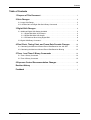
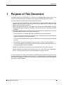
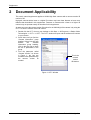
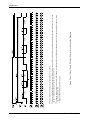
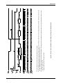
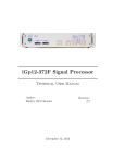
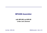
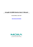
USER’S MANUAL SUPPLEMENT
Document Number: DA00073602
Release Date: 4 April 2006
For customers in the U.S.A.
This equipment has been tested and found to comply with the limits for a Class A digital device,
pursuant to Part 15 of the FCC Rules. These limits are designed to provide reasonable protection
against harmful interference when the equipment is operated in a commercial environment. This
equipment generates, uses, and can radiate radio frequency energy and, if not installed and used
in accordance with the instruction manual, may cause harmful interference to radio communications. Operation of this equipment in a residential area is likely to cause harmful interference in
which case the user will be required to correct the interference at his own expense.
You are cautioned that any changes or modifications not expressly approved in this manual could
void your authority to operate this equipment.
The shielded interface cable recommended in this manual must be used with this equipment in
order to comply with the limits for a computing device pursuant to Subpart J of Part 15 of FCC
Rules.
For customers in Canada
This apparatus complies with the Class A limits for radio noise emissions set out in Radio Interference Regulations.
Pour utilisateurs au Canada
Cet appareil est conforme aux normes Classe A pour bruits radioélectriques, spécifiées dans le
Règlement sur le brouillage radioélectrique.
Life Support Applications
These products are not designed for use in life support appliances, devices, or systems where
malfunction of these products can reasonably be expected to result in personal injury. Basler customers using or selling these products for use in such applications do so at their own risk and
agree to fully indemnify Basler for any damages resulting from such improper use or sale.
Warranty Note
Do not open the housing of the camera. The warranty becomes void if the housing is opened.
All material in this publication is subject to change without notice and is copyright Basler
Vision Technologies.
Contacting Basler Support Worldwide
Europe:
Basler AG
Ander Strusbek 60 - 62
22926 Ahrensburg
Germany
Tel.: +49-4102-463-500
Fax.: +49-4102-463-599
[email protected]
Americas:
Basler, Inc.
740 Springdale Drive, Suite 100
Exton, PA 19341
U.S.A.
Tel.: +1-877-934-8472
Fax.: +1-877-934-7608
[email protected]
Asia:
Basler Asia Pte. Ltd
8 Boon Lay Way
# 03 - 03 Tradehub 21
Singapore 609964
Tel.: +65-6425-0472
Fax.: +65-6425-0473
[email protected]
www.basler-vc.com
DRAFT
Contents
Table of Contents
1 Purpose of This Document . . . . . . . . . . . . . . . . . . . . . . . . . . . . . . . . . . . . . . . . . . . 1
2 Gain Changes . . . . . . . . . . . . . . . . . . . . . . . . . . . . . . . . . . . . . . . . . . . . . . . . . . . . . . . . 2
2.1 Larger Gain Range . . . . . . . . . . . . . . . . . . . . . . . . . . . . . . . . . . . . . . . . . . . . . . . . . . . 2
2.2 Left Side Gain and Right Side Gain Binary Commands . . . . . . . . . . . . . . . . . . . . . . . 3
3 Digital Shift Changes . . . . . . . . . . . . . . . . . . . . . . . . . . . . . . . . . . . . . . . . . . . . . . . . . 4
3.1 Additional Digital Shift Setting Available . . . . . . . . . . . . . . . . . . . . . . . . . . . . . . . . . . . 4
3.1.1 Digital Shift With 10 Bit Output . . . . . . . . . . . . . . . . . . . . . . . . . . . . . . . . . . . . . 4
3.1.2 Digital Shift With 8 Bit Output . . . . . . . . . . . . . . . . . . . . . . . . . . . . . . . . . . . . . . 6
3.1.3 Precautions When Using Digital Shift . . . . . . . . . . . . . . . . . . . . . . . . . . . . . . . . 8
3.2 Digital Shift Binary Command . . . . . . . . . . . . . . . . . . . . . . . . . . . . . . . . . . . . . . . . . . . 9
4 Pixel Clock, Timing Chart, and Frame Rate Formula Changes . . . . . . . 10
4.1 Calculating the Maximum Allowed Frame Rate Based on the AOI Size . . . . . . . . . 13
4.2 Calculating the Maximum Allowed Frame Rate Based on Binning . . . . . . . . . . . . . 13
5 Timer 1 and Timer 2 Binary Commands . . . . . . . . . . . . . . . . . . . . . . . . . . . . . 14
5.1 Timer 1 Binary Command . . . . . . . . . . . . . . . . . . . . . . . . . . . . . . . . . . . . . . . . . . . . . 14
5.2 Timer 2 Binary Command . . . . . . . . . . . . . . . . . . . . . . . . . . . . . . . . . . . . . . . . . . . . . 15
6 Exposure Control Recommendation Changes . . . . . . . . . . . . . . . . . . . . . . . 16
Revision History . . . . . . . . . . . . . . . . . . . . . . . . . . . . . . . . . . . . . . . . . . . . . . . . . . . . . . . i
Feedback . . . . . . . . . . . . . . . . . . . . . . . . . . . . . . . . . . . . . . . . . . . . . . . . . . . . . . . . . . . . . . ii
Basler A202k High Gain
I
Contents
II
DRAFT
Basler A202k High Gain
DRAFT
1
Supplement
Purpose of This Document
The Basler A202k High Gain camera is a variant of the standard Basler A202k camera. The
purpose of this document is to describe the unique aspects of A202k High Gain cameras.
The unique aspects of A202k High Gain camera are listed below.
• As the name implies, A202k High Gain cameras have a higher available gain range than
standard A202k cameras. The gain range and the gain related binary commands for high
gain cameras are detailed in Section 3.
• A202k High Gain cameras have more digital shift settings than standard A202k cameras.
The digital shift settings and digital shift binary commands for high gain cameras are detailed
in Section 4.
• A202k High Gain cameras use a 36 MHz pixel clock rather than the 40 MHz pixel clock used
on standard A202k cameras. This change means that:
- The timing charts for the A202k High Gain are different from standard cameras.
- The camera’s maximum frame rate at full resolution is 43 frames per second rather than 48
frames per second as on standard cameras.
- The formulas for calculating the maximum allowed frame rate are different from standard
cameras.
- The meaning of the binary commands used to set Timer 1 and Timer 2 have changed.
- The recommendations for controlling exposure in ExSync programmable mode and in Freerun programmable mode have changed.
Section 5 shows the timing charts and the frame rate formulas for high gain cameras.
Section 6 explains the change to the meaning of the Timer 1 and Timer 2 binary commands.
Section 7 lists the exposure control recommendations for high gain cameras.
In all other respects, the operation and features of A202k High Gain cameras are identical to the
operation and features on standard A202k cameras. For a full description of an A202k High Gain
camera and its capabilities, this document must be used together with the A202k User’s Manual
(document number DA04400x).
Basler A202k High Gain
1
Supplement
2
DRAFT
Document Applicability
This user’s manual supplement applies to A202k High Gain cameras with a camera version ID
number of 02.
High gain cameras with a lower or a higher ID number may have fewer features or have more
features than described in this supplement. Features on cameras with a lower or a higher ID
number may not operate exactly as described in this supplement.
An easy way to see the camera version ID number for an A202k High Gain camera is by using the
CCT+. To see the camera version ID number:
1. Double click the CCT+ icon on your desktop or click Start ⇒ All Programs ⇒ Basler Vision
Technologies ⇒ CCT+ ⇒ CCT+. The CCT+ window will open and the software will connect
to your camera.
2. Scroll down until you find the
“Camera Information” group
heading. If there is a plus sign
beside
the
Camera
Information group heading,
click on the plus sign to show
the list of parameters in the
group.
3. Find the parameter called
“Camera Version.” As shown
in Figure 1, the last two
numbers of this parameter are
the camera version ID
number.
This is the
camera
version
ID Number.
Figure 1: CCT+ Window
2
Basler A202k High Gain
DRAFT
3
Supplement
Gain Changes
3.1 Larger Gain Range
The major difference between the standard camera and the high gain version is the gain range.
On standard cameras, the gain can be programmed on a decimal scale that ranges from 288 to
569 (0x0120 to 0x0239). At the highest gain setting on a standard camera, the gain will be 12 dB.
On the high gain version, gain can be programmed on a decimal scale that ranges from 288 to
1023 (0x0120 to 0x03FF). The settings result in the following amplifications:
Decimal Number (DN)
Hexadecimal
dB
Factor
288
0x0120
0
x1
1023
0x03FF
28.06
x25
Table 1: Gain Settings on a High Gain Camera
If you know the decimal number (DN) setting for the gain on a high gain camera, the equivalent
decibel value can be calculated using the following equations:
658 + DN ⎞
⎛ --------------------------- – 8.15
10 ⎝ 658 – DN ⎠
When DN setting = 288 ... 511
Gain in dB = 20 log
When DN setting = 512 ... 1023
Gain in dB = .0354 (DN) – 8.15
L
In normal operation, a gain setting lower than 288 (0x0120) should not be used.
When the gain setting is lower than 288, the sensor output signal that is mapped to
the input of the ADCs will not be linear.
Basler A202k High Gain
3
DRAFT
Supplement
3.2 Left Side Gain and Right Side Gain Binary
Commands
On high gain cameras, the data range for the left side gain and the right side gain binary
commands is larger than on standard cameras. The larger range is shown in the tables below.
Left Side Gain
Purpose:
To set the gain for the left side of the CCD array or to read the current left side gain setting.
Type:
This is a read or write command.
Read Command:
Response:
Write Command:
Response:
Data Format:
Data Range:
Cmd-ID
0x80
R/W-Flag
1
Data Length
2
Data
-
Cmd-ID
0x80
R/W-Flag
0
Data Length
2
Data
2 Bytes
Cmd-ID
0x80
R/W-Flag
0
Data Length
2
Data
2 Bytes
None
Byte 1
Low byte of left side gain setting
Byte 2
High byte of left side gain setting
Left side gain settings can range from 288 to 1023 (0x0120 to 0x03FF).
Right Side Gain
Purpose:
To set the gain for the right side of the CCD array or to read the current right side gain
setting.
Type:
This is a read or write command.
Read Command:
Response:
Write Command:
Response:
Data Format:
Data Range:
4
Cmd-ID
0x82
R/W-Flag
1
Data Length
2
Data
-
Cmd-ID
0x82
R/W-Flag
0
Data Length
2
Data
2 Bytes
Cmd-ID
0x82
R/W-Flag
0
Data Length
2
Data
2 Bytes
None
Byte 1
Low byte of right side gain setting
Byte 2
High byte of right side gain setting
Right side gain settings can range from 288 to 1023 (0x0120 to 0x03FF).
Basler A202k High Gain
DRAFT
4
Supplement
Digital Shift Changes
4.1 Additional Digital Shift Setting Available
On standard cameras, the digital shift feature has “shift once” and “shift twice” settings available.
On high gain cameras, a “shift three times” setting has been added. The description of the digital
shift feature that appears below includes the additional setting.
Digital Shift On High Gain Cameras
The “digital shift” feature lets you change the group of bits that is output from each ADC. Using
the digital shift feature will effectively multiply the output of the camera by 2 times, 4 times or 8
times. Digital shift works differently depending on whether the camera is set for 10 bit output or for
8 bit output. The digital shift description that starts on page 5 applies when the camera is operating
in 10 bit output mode. The description that starts on page 7 applies when the camera is operating
in 8 bit output mode.
Page 9 describes precautions that you must observe to effectively use the digital shift feature.
You can set digital shift using either the Camera Configuration Tool Plus or binary commands.
With the configuration tool, you use the Digital Shift setting in the Output group to set digital shift.
With binary commands, you use the Digital Shift command.
4.1.1 Digital Shift With 10 Bit Output
No Shift
The A202k High Gain camera uses 10 bit ADCs to
digitize the output from the CCD sensor. When the
camera is operating in 10 bit output mode with no
digital shift, it simply transmits the 10 bits that are
output from each ADC.
Shift Once
When the camera is set to shift once, the output
from the camera will include bit 8 through bit 0 from
each ADC along with a zero as an LSB.
The result of shifting once is that the output of the
camera is effectively doubled. For example,
assume that the camera is set for no shift, that it is
viewing a uniform white target, and that under these
conditions the reading for the brightest pixel is 100.
If you changed the digital shift setting to shift once,
the reading would increase to 200.
Basler A202k High Gain
5
DRAFT
Supplement
L
Note that if bit 9 is set to 1, all of the other bits will automatically be set to 1. This
means that you should only use the shift once setting when your pixel readings in
10 bit mode with no digital shift are all below 512.
Since the shift once setting requires that the least significant bit always be "0", no
odd gray values can be output. In this case, the gray value scale will only include
gray values of 2, 4, 6 and so forth. The absence of some gray values is commonly
called "Missing Codes”.
Shift Twice
When the camera is set to shift twice, the output
from the camera will include bit 7 through bit 0
from each ADC along with two zeros as LSBs.
The result of shifting twice is that the output of the
camera is effectively multiplied by four. For
example, assume that the camera is set for no
shift, that it is viewing a uniform white target, and
that under these conditions the reading for the
brightest pixel is 100. If you changed the digital
shift setting to shift twice, the reading would
increase to 400.
L
Note that if bit 9 or bit 8 is set to 1, all of the other bits will automatically be set to 1.
This means that you should only use the shift twice setting when your pixel readings
in 10 bit mode with no digital shift are all below 256.
Since the shift twice setting requires that the two least significant bits always be "0",
the gray value scale will only include every 4th gray value. For example, 4, 8, 16
and so forth.
Shift Three Times
When the camera is set to shift three times,
the output from the camera will include bit 6
through bit 0 from each ADC along with
three zeros as LSBs.
The result of shifting three times is that the
output of the camera is effectively multiplied
by eight. For example, assume that the
camera is set for no shift, that it is viewing a
uniform white target, and that under these
conditions the reading for the brightest pixel
is 100. If you changed the digital shift setting
to shift three times, the reading would
increase to 800.
6
Basler A202k High Gain
DRAFT
L
Supplement
Note that if bit 9, bit 8 or bit 7 is set to 1, all of the other bits will automatically be set
to 1. This means that you should only use the shift three times setting when your
pixel readings in 10 bit mode with no digital shift are all below 128.
Since the shift three times setting requires that the three least significant bits always
be "0", the gray value scale will only include every 8th gray value. For example, 8,
16, 24 and so forth.
4.1.2 Digital Shift With 8 Bit Output
No Shift
The A202k High Gain camera uses 10 bit ADCs to
digitize the output from the CCD sensor. When the
camera is operating in 8 bit output mode with no digital
shift, it drops the least two significant bits from each
ADC and transmits the 8 most significant bits (bit 9
through bit 2).
Shift Once
When the camera is set to shift once, the output from
the camera will include bit 8 through bit 1 from each
ADC.
The result of shifting once is that the output of the
camera is effectively doubled. For example, assume
that the camera is set for no shift, that it is viewing a
uniform white target and that under these conditions
the reading for the brightest pixel is 20. If you changed
the digital shift setting to shift once, the reading would
increase to 40.
L
Note that if bit 9 is set to 1, all of the other bits will automatically be set to 1. This
means that you should only use the shift once setting when your pixel readings in
8 bit mode with no digital shift are all below 128.
Basler A202k High Gain
7
DRAFT
Supplement
Shift Twice
When the camera is set to shift twice, the output from
the camera will include bit 7 through bit 0 from each
ADC.
The result of shifting twice is that the output of the
camera is effectively multiplied by four. For example,
assume that the camera is set for no shift, that it is
viewing a uniform white target, and that under these
conditions the reading for the brightest pixel is 20. If
you changed the digital shift setting to shift twice, the
reading would increase to 80.
L
Note that if bit 9 or bit 8 is set to 1, all of the other bits will automatically be set to 1.
This means that you should only use the shift twice setting when your pixel readings
in 8 bit mode with no digital shift are all below 64.
Shift Three Times
When the camera is set to shift three times, the
output from the camera will include bit 6 through
bit 0 from each ADC along with a zero as the
LSB.
The result of shifting three times is that the output
of the camera is effectively multiplied by eight.
For example, assume that the camera is set for
no shift, that it is viewing a uniform white target
and that under these conditions the reading for
the brightest pixel is 20. If you changed the digital
shift setting to shift three times, the reading would
increase to 160.
L
Note that if bit 9, bit 8 or bit 7 is set to 1, all of the other bits will automatically be set
to 1. This means that you should only use the shift once setting when your pixel
readings in 8 bit mode with no digital shift are all below 32.
Since the shift three times setting requires that the least significant bit always be
"0", no odd gray values can be output. In this case, the gray value scale will only
include gray values of 2, 4, 6 and so forth. The absence of some gray values is commonly called "Missing Codes”.
8
Basler A202k High Gain
DRAFT
Supplement
4.1.3 Precautions When Using Digital Shift
There are several checks and precautions that you must follow before using the digital shift feature
on high gain cameras. The checks and precautions differ depending on whether you will be using
the camera in 10 bit output mode or in 8 bit output mode.
If you will be using the camera in 10 bit output mode, make this check:
1. Use binary commands or the Video Data Output Mode setting in the Output group on the
configuration tool to put the camera in 10 bit output mode.
2. Use binary commands or the Digital Shift setting in the Output group on the configuration tool
to set the camera for no digital shift.
3. Check the output of the camera under your normal lighting conditions with no digital shift
and note the readings for the brightest pixels.
• If any of the readings are above 512, do not use digital shift.
• If all of the readings are below 512, you can safely use the shift once (2X) digital shift setting.
• If all of the readings are below 256, you can safely use the shift once (2X) or shift twice
(4X) digital shift setting.
• If all of the readings are below 128, you can safely use the shift one (2X), shift twice (4X)
or shift three times (8X) digital shift setting.
If you will be using the camera in 8 bit output mode, make this check:
1. Use binary commands or the Video Data Output Mode setting in the Output group on the
configuration tool to put the camera in 8 bit output mode.
2. Use the binary commands or the Digital Shift setting in the Output group on the configuration
tool to set the camera for no digital shift.
3. Check the output of the camera under your normal lighting conditions with no digital shift
and note the readings for the brightest pixels.
• If any of the readings are above 128, do not use digital shift.
• If all of the readings are below 128, you can safely use the shift once (2X) digital shift setting.
• If all of the readings are below 64, you can safely use the shift once (2X) or shift twice (4X)
digital shift setting.
• If all of the readings are below 32, you can safely use the shift once (2X), shift twice (4X)
or shift three times (8X) digital shift setting.
Basler A202k High Gain
9
DRAFT
Supplement
4.2 Digital Shift Binary Command
On high gain cameras, a “shift three times” setting has been added to the data formats for the
digital shift binary command. The additional setting is shown in the table below.
Purpose:
To enable or disable digital shift.
Type:
This is a read or write command.
Read Command:
Response:
Write Command:
Response:
Data Format:
Cmd-ID
0xA5
R/W-Flag
1
Data Length
1
Data
-
Cmd-ID
0xA5
R/W-Flag
0
Data Length
1
Data
1 Byte
Cmd-ID
0xA5
R/W-Flag
0
Data Length
1
Data
1 Byte
None
Byte 1
ID
10
An ID that specifies the digital shift status
(see the table below).
Digital Shift
0x00
No digital shift
0x01
Digital shift once
(multiples output 2X)
0x02
Digital shift twice
(multiples output 4X)
0x03
Digital shift thee times
(multiples output 8X)
Basler A202k High Gain
DRAFT
5
Supplement
Pixel Clock, Timing Chart, and Frame
Rate Formula Changes
A202k High Gain cameras use a 36 MHz pixel clock rather than the 40 MHz clock used on
standard cameras. This means that the pixel timings and the formulas for calculating the
maximum allowed frame rate are different on high gain cameras.
Figure 2 shows the pixel timing chart when a high gain camera is operating with level controlled
exposure. Figure 3 shows the pixel timing chart when a high gain camera is operating with
programmable exposure.
Section 5.1 describes how to calculate the maximum allowed frame rate on high gain cameras
based on the size of the area of interest.
Section 5.2 describes how to calculate the maximum allowed frame rate on high gain cameras
based on the use of the binning feature.
Note that when a high gain camera is used with binning enabled, the pixel clock will operate at 18
MHz rather than at 20 MHz as it does on standard cameras.
Basler A202k High Gain
11
12
[3]
[2]
[1]
Figure 2: Dual 10 Bit or Dual 8 Bit Output Mode with Level Controlled Exposure
TIMING CHARTS ARE NOT DRAWN TO SCALE
The diagram assumes that the area of interest (AOI) feature is not being used. With the AOI feature enabled, the number of lines transferred and the number of pixels
in each line could be smaller.
In the level controlled exposure mode, the fall of ExSync starts exposure. If ExSync falls while a frame is being transferred (while frame valid is high), one line valid
low time immediately following the fall of ExSync will be 17.1 µs.
The line valid low time is 8.8 µs except as described in note 2 below.
Supplement
DRAFT
Basler A202k High Gain
Basler A202k High Gain
[3]
[2]
[1]
Figure 3: Dual 10 Bit or Dual 8 Bit Output Mode with Programmable Exposure
TIMING CHARTS ARE NOT DRAWN TO SCALE
The diagram assumes that the area of interest (AOI) feature is not being used. With the AOI feature enabled, the number of lines transferred and the number of pixels
in each line could be smaller.
In the programmable exposure mode, the rise of ExSync starts exposure. If ExSync rises while a frame is being transferred (while frame valid is high), one line valid
low time immediately following the fall of ExSync will be 17.1 µs.
The line valid low time is 8.8 µs except as described in note 2 below.
DRAFT
Supplement
13
DRAFT
Supplement
5.1 Calculating the Maximum Allowed Frame Rate
Based on the AOI Size
When the area of interest feature is used, the camera’s maximum allowed frame rate increases.
The amount that the maximum frame rate increases depends on the number of lines included in
the area of interest. The smaller the number of lines in the area of interest, the higher the
maximum frame rate. The maximum allowed frame rate for A202k High Gain cameras can be
calculated using the following formula:
1
Maximum frames per second = -----------------------------------------------------------------------------------------------------------------------------------( LI × 22.77 µs ) + [ ( 1004 – LI ) × 8.2 µs ] + 132.9 µs
Where: LI = the number of lines includes in the area of interest
5.2 Calculating the Maximum Allowed Frame Rate
Based on Binning
When vertical binning or full binning is used, the cameras maximum allowed frame rate increases.
The maximum allowed frame rate for A202k High Gain cameras can be calculated using the
following formula:
1
Maximum frames per second = --------------------------------------------------------------------------------------------------------------------------------------( LI × 30.96 µs ) + [ ( 502 – LI ) × 16.39 µs ] + 132.9 µs
Where: LI = the number of lines in the area of interest
(Remember that when you are working with vertical binning or full binning, the
resolution of the sensor is effectively reduced to 502 lines.)
L
14
Horizontal binning has no effect on the frame rate.
Basler A202k High Gain
DRAFT
6
Supplement
Timer 1 and Timer 2 Binary
Commands
The Timer 1 and Timer 2 parameters are used to set several aspects of exposure timing on A202k
cameras. On A202k High Gain cameras, the usage of the binary commands for setting Timer 1
and Timer 2 has changed.
On standard A202k cameras, when you use the Timer 1 binary command to set the value of Timer
1, the setting represents a value in microseconds. For example, if Timer 1 is set to a value of 10,
this represents 10 µs. The same is true for Timer 2 on a standard camera.
On A202k High Gain cameras, the setting for Timer 1 represents a multiple of 0.88889 µs. For
example, if you use the Timer 1 binary command to set the value of Timer 1 to 10, the setting
would represent a value of 10 x 0.88889 µs or 8.8889 µs. The same is true for Timer 2 on a high
gain camera.
Sections 6.1 and 6.2 show the details of the Timer 1 and Timer 2 commands on A202k High Gain
cameras.
6.1 Timer 1 Binary Command
Purpose:
To set Timer 1 or to read the current Timer 1 setting. Timer 1 is used when the camera is
operating in ExSync programmable mode or in free-run mode. See Section 3.2 for details.
Type:
This is a read or write command.
Read Command:
Response:
Write Command:
Response:
Data Format:
Data Range:
Cmd-ID
0xA6
R/W-Flag
1
Data Length
3
Data
-
Cmd-ID
0xA6
R/W-Flag
0
Data Length
3
Data
3 Bytes
Cmd-ID
0xA6
R/W-Flag
0
Data Length
3
Data
3 Bytes
None
Byte 1
Low byte of the Timer 1 setting
Byte 2
Mid byte of the Timer 1 setting
Byte 3
High byte of the Timer 1 setting
Timer 1 setting can range from 13 (0x00000D) to 16777215 (0xFFFFFF).
The Timer 1 setting represents a multiple of 0.88889 µs. For example, if the
Timer 1 setting is 100, then the value of Timer 1 would be:
100 x 0.88889 µs = 88.889 µs
Basler A202k High Gain
15
DRAFT
Supplement
6.2 Timer 2 Binary Command
Purpose:
To set Timer 2 or to read the current Timer 2 setting. Timer 2 is used when the camera is
operating in free-run mode. See Section 3.2 for details.
Type:
This is a read or write command.
Read Command:
Response:
Write Command:
Response:
Data Format:
Data Range:
Cmd-ID
0xA7
R/W-Flag
1
Data Length
3
Data
-
Cmd-ID
0xA7
R/W-Flag
0
Data Length
3
Data
3 Bytes
Cmd-ID
0xA7
R/W-Flag
0
Data Length
3
Data
3 Bytes
None
Byte 1
Low byte of the Timer 2 setting
Byte 2
Mid byte of the Timer 2 setting
Byte 3
High byte of the Timer 2 setting
Timer 2 settings can range from 42 (0x00002a) to 16777215 (0xFFFFFF).
The Timer 2 setting represents a multiple of 0.88889 µs. For example, if the
Timer 2 setting is 100, then the value of Timer 2 would be:
100 x 0.88889 µs = 88.889 µs
16
Basler A202k High Gain
DRAFT
7
Supplement
Exposure Control Recommendation
Changes
The User’s Manual for standard A202k cameras contains a set of “Recommendations for
Controlling Exposure in ExSync Programmable Mode” and a set of “Recommendations for
Controlling Exposure in Free-run Programmable Mode”. The recommendations for A202k High
Gain cameras are different from standard cameras. The recommendations for high gain cameras
are listed below.
For ExSync Programmable Mode
If you are using an A202k High Gain camera that is set for ExSync programmable exposure
control, follow these guidelines.
• The ExSync signal must toggle.
• The ExSync signal must remain high for at least 4 µs.
• The minimum setting for Timer 1 is 13. (This represents 13 x 0.8889 µs or 11.56 µs.)
• The programmed exposure time must be less than the ExSync signal period.
• If the AOI and Binning features are not being used, the minimum ExSync signal period is
23.0 ms.
• If the AOI is being used, the minimum ExSync period is equal to 1/Maximum Frame Rate
where the maximum frame rate is determined by the formula that appears on page 14 of this
supplement.
• If the binning feature is being used, the minimum ExSync period is equal to 1/Maximum
Frame Rate where the maximum frame rate is determined by the formula that appears on
page 14 of this supplement.
For Free-run Mode
If you are using an A202k High Gain camera that is set for Free-run exposure control, follow these
guidelines.
• The minimum setting for Timer 1 is 13. (This represents 13 x 0.88889 µs or 11.556 µs.)
• The minimum setting for Timer 2 is 42. (This represents 42 x 0.88889 µs or 37.333 µs.)
• The actual length of the exposure time will be equal to the programmed time plus 89.9 µs.
• In free-run mode, the period of the internal control signal is equal to:
[ (Timer 1 setting + Timer 2 setting) x 0.88889 µs ] + 89.9 µs
If the AOI and Binning features are not being used, Timer 1 and Timer 2 must be set so that
the result of this formula is greater than 23.0 ms.
• If the AOI is being used, the period of the internal control signal (as determined by the above
formula) must be greater than 1/Maximum Frame Rate where the maximum frame rate is
determined by the formula that appears on page 14 of this supplement.
• If the binning feature is being used, the period of the internal control signal (as determined by
the above formula) must be greater than 1/Maximum Frame Rate where the maximum frame
rate is determined by the formula that appears on page 14 of this supplement.
Basler A202k High Gain
17
Supplement
18
DRAFT
Basler A202k High Gain
DRAFT
Revision History
Revision History
Doc. ID Number
Date
Changes
DA00073601
2 March 2005
Initial release of this document.
DA00073602
4 April 2006
Revised the entire document to reflect the changes made for the
36 MHz version of the high gain camera.
Basler A202k High Gain
i
Feedback
DRAFT
Feedback
Your feedback will help us improve our documentation. Please click the link below to access an online
feedback form. Your input will be greatly appreciated.
http://www.baslerweb.com/umfrage/survey.html
ii
Basler A202k High Gain