1
v 1.25
2015/02/20
U-See User Manual -
Table of Contents
1.General System Introduction..............................................................................................4
1.1 Concept of system operation......................................................................................5
2.U-See..................................................................................................................................6
2.1 Introduction.................................................................................................................6
2.2 Recommended Hardware...........................................................................................6
2.3 Software compatibility.................................................................................................6
2.3.1 Windows Installation............................................................................................7
2.4 Units and locale..........................................................................................................9
2.5 Map View..................................................................................................................10
2.5.1 On Map icons.....................................................................................................11
2.5.2 On Map Information Overlay.............................................................................12
2.5.3 GPWS Information display................................................................................13
2.5.4 Interacting with the Map View...........................................................................14
2.6 File Menu..................................................................................................................15
2.6.1 Communications................................................................................................15
2.6.2 Record Data......................................................................................................19
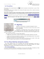
2.7 Map Menu.................................................................................................................19
2.8 View Menu: Real time information windows.............................................................19
2.8.1 Sensors Summary.............................................................................................19
2.8.2 Relative GPS Status (Optional).........................................................................21
2.8.3 Video Capture (Optional)...................................................................................23
2.8.4 Synthetic View / Artificial Horizon......................................................................24
2.8.5 State..................................................................................................................25
2.8.6 Joystick..............................................................................................................33
2.8.7 Engine Data.......................................................................................................33
2.8.8 Vibration frequency Graphs...............................................................................36
2.8.9 Time log.............................................................................................................37
2.9 Pre-Flight Menu........................................................................................................37
2.9.1 Checklist............................................................................................................38
2.9.2 Runway..............................................................................................................39
2.9.3 Advanced Runway (Optional)............................................................................39
2.9.4 Flight-Plan.........................................................................................................40
2.9.5 Bingo Time.........................................................................................................44
2.9.6 Pattern Generator..............................................................................................44
2.9.7 Flightplan From File...........................................................................................46
2.10 Command Menu.....................................................................................................47
2.10.1 Command window...........................................................................................47
2.10.2 Camera command window..............................................................................54
2.10.3 Landing Control window (Optional).................................................................55
2.10.4 Command Aux Surfaces..................................................................................56
2.10.5 Engine management.......................................................................................56
2.11 Post-Flight Menu.....................................................................................................57
2.11.1 Record Data → .txt..........................................................................................57
2.12 Settings Menu.........................................................................................................60
2.12.1 Gains adjustment (Optional)............................................................................60
2.12.2 Configure GCS Hardware(Optional)...............................................................61
2.12.3 Manual Trims...................................................................................................61
Document Version 1.25
2
U-See User Manual 2.12.4 Camera Joystick..............................................................................................62
2.12.5 Payload setting window...................................................................................63
2.12.6 Air Data System Settings.................................................................................63
2.12.7 Servos.............................................................................................................64
2.12.8 Pitch Throttle Curves.......................................................................................67
2.12.9 Magnetometer Calibration...............................................................................68
2.12.10 U-See settings...............................................................................................69
2.12.11 Auto align sensors.........................................................................................72
2.12.12 Save Changes...............................................................................................72
Appendix A Matlab script for data analysis..........................................................................73
Appendix B Matlab script for pointing camera coordinates.................................................75
Appendix C Change log.......................................................................................................77
Document Version 1.25
3
U-See User Manual - General System Introduction
1. General System Introduction
Airelectronics has developed a complete solution for both rotary and fixed wing UAVs. The
system is composed of:
•
U-Pilot
•
U-Ground
•
U-See
U-Pilot takes care of the vehicle from Take-off to Landing. It is completely adaptable to any
aircraft including fixed wing, multi-copters and helicopters.
U-Pilot is completely capable of following a flight plan with up to 200 points (real time
editable). Once the flight plan is loaded on the U-Pilot it is independent of operator
instructions. In case of a failure in the communications, U-Pilot starts a Landing maneuver
which would safely land the UAV on the Runway Point.
Thanks to its versatility U-Pilot can control any device on board the UAV such as cameras,
parachutes and others. These devices can be real time controlled by a Computer Operator
or by U-Pilot automatically.
U-Pilot has, working in parallel:
•
Up to 33 PWM (Pulse-Width Modulation) outputs or even more if necessary,
•
3 ADC inputs (Analogical Digital Converter) to monitor the voltages of three
batteries on the UAV
•
4 serial ports RS232 to communicate with payloads, external magnetometers, etc.
•
A radio with up to 100 km1
•
GPS, dynamic and static pressure sensors, a magnetometer, gyroscopes and
accelerometers.
U-Pilot is built using a two parallel microprocessor approach:
•
One processor takes care of the state estimator and controls the UAV using
hardware acceleration to calculate high speed algorithms.
•
Another processor takes care of the mission at high level and the communications
with the U-Ground and Payloads management.
•
the processors do not waste any time doing low level tasks.
Due to the fact that those two processors are working in parallel and there is dedicated
electronics taking care of all the serial ports, sensors, inputs and outputs the system is
capable of recalculating its position, orientation and closing control loops at the speed of
1000 Hz. This high speed gives the UAV huge navigation accuracy and control.
On the ground segment, we have both U-Ground and U-See.
U-Ground is a control station with the other end of the radio link communicating the U-Pilot
with the U-See software.
U-See software is a user friendly program that runs in any personal computer running
Windows or Linux2.
1 Range may vary with the frequency band used. Default is 900 MHz but legal limitations in
some countries may change this.
2 MAC OS X can be available upon request, but it is considered a second-tier platform and
some features may be unavailable.
Document Version 1.25
4
U-See User Manual - General System Introduction
Through U-See, the UAV operator can inspect the current state of the mission and
command it in real-time.
All the U-Pilot configuration is done by Airelectronics staff so the End User does not have to
waste any time setting the internal parameters of the system.
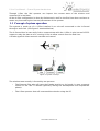
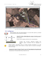
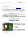
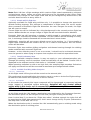
1.1 Concept of system operation
The system is made up of a U-Pilot installed in an aircraft connected to the U-Ground
through a radio link. (See figure 1 attached below)
The U-Ground has its own radio link to communicate with the U-Pilot. It also has an RS-232
output to relay the data to a PC running U-See to allow control from the End User.
A Futaba Joystick allows manual override and control.
Figure 1: System concept
The mission team usually is formed by two persons:
•
The External Pilot who will have the Futaba Joystick on its hands, in case a manual
control of the UAV is desired (specially during the development and adjustment
phase).
•
The U-See operator that will command the mission using the PC.
Document Version 1.25
5
U-See User Manual - U-See
2. U-See
2.1 Introduction
U-See is the software the operator will use to monitor and command the mission. All the
information displayed by U-See comes from U-Pilot. This way the operator can be sure that
the info displayed on the map is the actual information being used on-board for navigation
and control.
The map engine connects to the Internet and fetches Geo-referenced maps and displays
them for you. The End User is not required to manually load maps and worry about their
alignment. However, it is possible to load such external maps through MapManager
application that is distributed alongside U-See, and choosing map theme display is
available in the settings dialog.
For operational deployments without Internet connectivity, U-See keeps a local cache of
already displayed locations
2.2 Recommended Hardware
U-See runs on a standard PC.
The recommended hardware is the MacBook Pro 13” with BootCamp and Microsoft
Windows 7.
Minimum hardware specification:
•
Intel Core i5 processor.
•
2GB RAM.
•
4 GB free hard drive.
•
OpenGL capable graphics Video Card.
•
13-inch (diagonal) screen.
•
1 RS-232 port or an available USB port with a serial USB to RS-232 converter.
•
1 Extra free USB port for license dongle.
All complex computer graphics drawn in U-See use OpenGL, the computer's video card is
computing all the information. As a result, the processor load is lower and it is free to
compute the mission information.
2.3 Software compatibility
U-See supports the main Operating Systems (Windows, Linux and MacOS X). However,
MacOS X is considered a second-tier platform and some functionality may not be available
when operating with MacOSX OS. Contact Airelectronics and we will provide you with the
software that better fits your requirements.
Document Version 1.25
6
U-See User Manual - Software compatibility
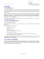
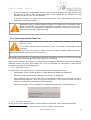
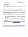
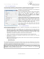
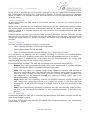
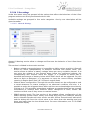
2.3.1 Windows Installation
To install U-See on Windows follow the steps:
–
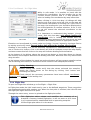
Execute U-See-1.0 Setup.exe (If asked about administrator permissions should be
given, say yes) supplied (The version 1.0 may change depending on the software
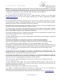
Figure 2: Installation process, step 1
version distributed). Click Yes button.
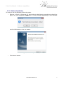
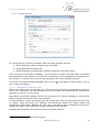
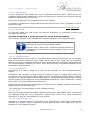
Figure 3: Installation process, step 2
–
Click Next> button
Document Version 1.25
7
U-See User Manual - Software compatibility
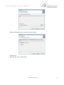
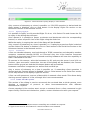
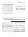
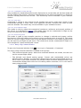
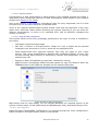
Figure 4: Installation process, step 3
–
Choose the destination location and click Next>
–
Click Next>
–
Wait for the copy of files finish
Figure 5: Installation process, step 4
Document Version 1.25
8
U-See User Manual - Software compatibility
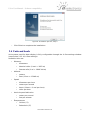
Figure 6: Installation process, step 5
–
Click Finish to complete the installation.
2.4 Units and locale
Unit system used for data display is fully configurable through the U-See settings window
(see section 2.12.10,U-See settings)
Available Units are:
•
•
•
•
•
Distance:
•
kilometers
•
Nautical miles (1 nmi = 1852 m)
•
Statute mile (1 mi = 1609.344 m)
Altitude
•
meters
•
Feet (1 foot = 0.3048 m)
Speed
•
kilometers per hour
•
meters per second
•
knots (1 knot = 1 nmi per hour)
•
miles per hour
Vertical speed indication
•
meter per second
•
feet per minute
Temperatures
•
Celsius (°C)
•
Fahrenheit (°F)
Document Version 1.25
9
U-See User Manual - Units and locale
Coordinates and angles are always shown using sexagesimal degrees. However
coordinates presentation format can be changed between decimal coordinates format
(e.g. 41.880263,-7.3828424)
and
sexagesimal
coordinates
format
(41°52'48.9468”N 7°22'58.23264W).
When necessary to input a decimal quantity, the decimal separator used is “.” (the dot)
and also in this document decimal quantities are presented in this way.
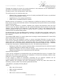
2.5 Map View
On start-up, the 0°,0° position is displayed with a drop-down menu bar and a toolbar.
Once the serial port is opened (See 2.6.1 Communications) and data starts arriving to USee, the proper aircraft position will be displayed through an icon and the map will
recenter.
Linked to the aircraft position icon, there is a small overlay summarizing UAV mode, speed
and altitude status. However the display of this overlay is optional and it is controlled
through the U-See Ground Settings dialog (see section 2.12.10,U-See settings)
To move the map click and drag on the screen using the left mouse button.
Zooming can be performed either by use of the mouse wheel, the keyboard shortcut
“Ctrl+ -” and “Ctrl + +” or the “Zoom In” and “Zoom Out” actions in the tool-bar present in
the main window.
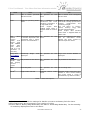
Over-imposed on the map, the user will see a set of lines and points that describe the
active and future operations of the UAV. The active task is always drawn in green, while all
the symbology relating non-active features is drawn in blue (e.g. Figure 6, a flight plan is
drawn in blue, i.e., it is inactive)
The UAV icon will leave behind a trail of color points. This color will reflect the climb speed.
Red for positive climb rate and blue for negative climb rate. 3
The operator can add additional windows on the drop-down menu as described on 2.8 View
Menu: Real time information windows.
3 The presence of this trail is controlled by the maps settings in the U-See Settings dialog.
Document Version 1.25
10
U-See User Manual - Map View
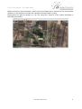
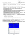
Figure 7: Example screenshot of U-See. Note different colours for active and standby elements, trail
with climb information and the small overlay
2.5.1 On Map icons
Home Position: This icon will be placed at U-Ground GPS position, provided
U-Ground GPS antenna has sky visibility.
Aircraft Position: Depending the type of aircraft, one of
these two icons will be placed on map at the reported UPilot position.
Future U-See releases will allow icon customization.
Landing Site Location: Reported Landing Site
Location, proper orientation will be displayed on
map.
Camera Target: Calculated center of camera pointing coordinates. It is only
shown when the option “Show camera on map” option is checked in Settings→
Ground Settings.
Commanded Camera Target: This blue circle will be painted on the position the
autopilot is trying to aim the camera, when in a Geo-referenced camera-mode,
the previous icon should be firmly inside this one.
Document Version 1.25
11
U-See User Manual - Map View
Flight-plan point: The number in the interior is the flight-plan
sequence number. When the autopilot is in flight-plan mode,
outer circle is colored in green, if not, blue is used instead.
If the point is the current flight-plan destination, a yellow circle
will enclose the icon.
Destination Point: This point is used to direct the aircraft when not in
flight-plan, take-off or landing modes. In Fixed Wing aircrafts, active
state will also include a representation of the orbit radio the aircraft will
fly once the DP is reached.
Landing Hold center: Only displayed with fixed wing aircrafts, this icon marks
the center of the hold pattern for landing ( See Section 2.10.1.4.5 Landing
mode)
2.5.1.1 Optionally available icons
Hereafter are listed those icons that only are displayed on some specific versions of the
Software when some optional feature is enabled. They are listed here for the sake of
completeness. These may not apply to your software version.
Base location: When operating in moving base mode using a relative
GPS, the base location and heading is displayed with this icon
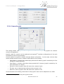
2.5.2 On Map Information Overlay
Linked to the aircraft position icon a small overlay will present basic status information:
1. Mode indication: The list of
mode abbreviation is found in
Table 2: Fixed Wing Modes Key.
and Table 3: Rotary Wing Modes
Key
2. IAS: Indicated Air Speed
3. ALT: Altitude in meters over sea
level.
4. GS: Ground Speed
5. AGL: Altitude
level. See note
above
ground
Figure 8: Basic Information Overlay
AGL information is calculated using a Digital Elevation Model (DEM for
short) incorporated into U-See.
Default DEM used in U-See has global coverage but, in exchange, its
accuracy at some points may be lacking. Errors as high as 150 m. can
exist.
Because of this, we advise to take AGL values with a pinch of salt, and
only for broad informational purposes. Never fully trust these values for in-flight
planning. A Safe terrain clearance should be kept at all times.
This warning still applies if high detail DEM is loaded instead of U-See default: DEMs
usually do NOT include obstacles (as buildings and antennas) and terrain may have
changed since the DEM preparation date because of human development.
Document Version 1.25
12
U-See User Manual - Map View
2.5.2.1 Optionally available map overlays
When operating in moving base mode and the feature is enabled, next to the base position
an overlay with information about course and speed of the moving base will be displayed.
This information is only available in some U-See versions and this section may not apply to
your version
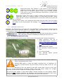
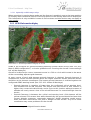
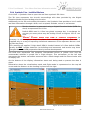
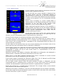
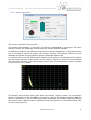
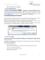
2.5.3 GPWS Information display
Ilustración 1: GPWS information display in action
GPWS is the acronym for Ground Proximity Warning System. When active (See 2.12.10.3
Maps & DEM configuration4) a circular gridded sector covering the aircraft’s surrounding 8
km. will be displayed.
Aircraft is located at its centre. Innermost sector is a 300 m. circle which state is the worst
of the surrounding adjacent grid elements.
At every corner of each grid element ground clearance is checked. Ground clearance is
computed as current aircraft altitude minus the digital elevation model predicted terrain
elevation at the element coordinates. The lowest ground clearance is checked against the
configured GPWS warning levels (See 2.12.10.1 Alarms & Warnings):
•
Ground clearance is negative of lower than the configured critical warning level.
Grid element will be red coloured. This means that the terrain at that location is
higher than current aircraft altitude, and a fly-to to this location without increase of
altitude will surely cause a loss of the aircraft because if a controlled flight into the
terrain.
•
Ground Clearance is between the critical and warning level. Grid element will be
yellow coloured. This means that while theoretically the ground should be lower that
current altitude, antennas, man-made obstacles, digital elevation model errors,
trees and other inaccuracies still pose a danger for the aircraft. A fly-to to these
coordinates may cause problems for the aircraft.
4 DEM is an acronym for Digital Elevation Model
Document Version 1.25
13
U-See User Manual - Map View
•
If Ground clearance is between warning and low altitude level, the grid element will
be painted in green. This shows that while there should be not problem at that
altitude, terrain is near to be a problem.
•
If ground clearance is above the low altitude level, the grid element will not be
painted to avoid map clutter.
Whenever using a Digital Elevation Model it is important to remember that
these are models, and models sometimes contain errors or inaccuracies.
GPWS overlay is provided for additional situational awareness but is not
substitute for proper flight planning.
2.5.4 Interacting with the Map View
Map interaction using the mouse has substantially changed starting at
version 1.720
If you have used previous versions of U-See in the past, review this section
carefully.
In case you are using an older version of U-See, contact Airelectronics for
obtaining previous revisions of this document.
Map view is the main way of interacting with UAV navigation control. At all times, the map
can be interacted with the left and right button of the mouse.
Right mouse button click opens a context menu, dragging the mouse with the left button
pressed moves the map and simple left click is reserved for interactions that change
navigation properties in the autopilot.
2.5.4.1 Right Button Menu
A right button click will bring up a menu containing the following entries:
•
Coordinates of the clicked position: longitude and latitude are displayed.
•
Elevation of the clicked point: Elevation of terrain is displayed 5
•
'Point Camera Here' action: This will command the camera to point here when in
Geo-referenced modes. This entry won't be shown if the “Show camera on map”
option is unchecked in Settings→ U-See Settings.
•
Distance From/To: Action to enable on map measuring (See following section)
Figure 9: Right button click menu
2.5.4.2 Measuring on the map
At any given time, measurements can be made on the map. This is accomplished by:
5 For proper description of vertical datum, please, contact Airelectronics.
Document Version 1.25
14
U-See User Manual - Map View
•
Right clicking on the first measurement point and selecting “Distance From” from
the context menu
•
Right clicking on the second measurement point and selecting “Distance To” from
the context menu.
•
Distance between the two points will be presented in the left bottom corner of the
map display, right above the scale display.
2.5.4.3 Left click interaction
Generally, Left button click sends through the radio up-link the order for the autopilot to
change the position of the “Destination Point”. Trough this action, the intention to change
the navigation target (while in the proper modes) is transmitted to the autopilot.
If autopilot has accepted this command the Destination Point should immediately move
right to the clicked position on the map.
It may happen, due to ambient noise and byte losing in the radio-link while operating at
long distance, that the destination point is not updated: shall this occur, just repeat the feft
click action.
Exceptions to the “Left button click set destination point” rule exist:
•
When editing a flight plan point (See Section 2.9.4 Flight-Plan) the left button click
rules are a bit different:
◦ Every flight-plan button has an “edit” mode in which the left click on the map
picks coordinates for this point. While in this mode, the cursor will be
transformed in a cross-hair and a tool-tip will be shown reading “Left Button
Picks ID Point N”
◦ When adding a new point to the flight-plan, left click will select the clicked
coordinates as point coordinates. This change in behavior will be indicated by a
cross-hair cursor and a tool-tip moving with the cursor that reads “Left Button
click appends ID Point X. Altitude will default to maintain minimum flight-plan
clearance”
•
Whenever the “Pattern Generation” tool window is opened left click on map will add
a point to the terrain outline (See Section 2.9.6 Pattern Generator)
2.6 File Menu
Under this menu are grouped all operations relating input and output of telemetry data.
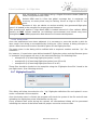
2.6.1 Communications
The communications dialog controls the source of telemetry data presented all through the
program. It is divided among communications with the primary UAV and communications
with other systems, be it other ground stations or secondary telemetry from other UAVs.
Document Version 1.25
15
U-See User Manual - File Menu
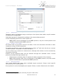
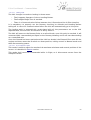
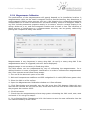
2.6.1.1 “Comms with UAV”
Figure 10: Comms with UAV dialog
At current version, primary telemetry data has three possible sources:
1. RS232 Telemetry data as supplied by U-Ground.
2. A previous flight recording file.
3. TCP/IP Telemetry received from another computer acting as a relay.
Only one source of primary telemetry can be active at a time, and only when connected
through RS232 to the paired U-Ground unit commands can be uploaded to the autopilot on
the aircraft, i.e. TCP/IP clients cannot command the UAV in the standard version 6.
To access the Communication Window click on the
file → Communications.
2.6.1.1.1
icon menu on the toolbar or go to
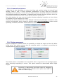
RS232 Telemetry (Serial Port section)
This is the main source of telemetry: A U-Ground unit connected to the computer through a
RS232 link. Telemetry will be decoded from the stream and presented all through the
program as soon as it is received.
Only while connected through the RS-232 serial port to U-Ground Software U-See will be
able to upload commands to the UAV autopilot.
To start operation, select the proper port the proper port from the drop-down list and click
on 'Open'. Upon successful port opening, the dialog will disable the 'Open' button and
enable the Close button. Besides this, the rest of the dialog will be disabled and the main
window will show a bar displaying current communications health.
Software will remember the last port used in previous sessions.
6 Remote control is enabled upon request.
Document Version 1.25
16
U-See User Manual - File Menu
Figure 11: Communications quality display in main window
Only a source of telemetry at a time is possible, so, if RS-232 operation is desired and the
Open button is disabled, click on Stop button in the Replay Flight File section or the
Disconnect button in the Network section
2.6.1.1.2
Replaying a flight file
It is possible to replay an old recorded flight. To do so, click Select File and choose the file
to replay in the dialog that will open.
Once opened it is possible to pause, accelerate and decelerate with the corresponding
buttons, or select a specific time of the flight using the slider bar.
While the replay is ongoing the rest of the dialog will be disabled.
Only a source of telemetry at a time is possible, so, if replaying a previous flight is desired
and the Select File button is disabled, click on Close button in the Serial Port section or the
Disconnect button in the Network section
2.6.1.1.3
Network client
U-See can decode telemetry received through a TCP/IP connection and relayed by another
computer connected through RS-232 to U-Ground. Only the U-See instance connected
physically to the serial port of the U-Ground receiving hardware will have the capability to
emit a command to the UAV7.
To operate in this manner, write the hostname (or IP) and port the server is and click on
Connect. Upon successful, connection, the rest of the dialog will be disabled, the Connect
button will be grayed out and the Disconnect button will be enabled.
Hostname resolution is supported, as well as IPv4 and IPv6 ips.
Only a source of telemetry at a time is possible, so, if networking client operation is
desired and the Connect button is disabled, click on Close button in the Serial Port section
or the Stop button in the Replay Flight File section.
U-See can still operate as a server of data while in network client mode. This allows daisy
chaining several copies of U-See, although this is not recommended.
2.6.1.2 Comms with other systems
This section of the dialog is used to re-transmit the received data to third systems, even
allowing a translation of protocol to allow intercommunication with different
manufacturer's system.
Current standard U-See version won't accept a command from a client connected to this
export facility. To allow such behaviour, please, contact Airelectronics with your request. 8
7 Modified versions that allow remote controlling are available on request.
8 Typical use-case for this feature is control handover over network.
Document Version 1.25
17
U-See User Manual - File Menu
Figure 12: Comms with other systems
2.6.1.2.1
Serial port for export
Telemetry data is re-exported using a serial-port. Port Speed, data width, stop bit number
and parity are configurable.
Said data exported is formatted according to the selected data protocol.
Current standard protocols for serial export are:
•
2.6.1.2.2
NMEA 0183: Due to limitations in the NMEA protocol, only the current position and
altitude is exported with NMEA protocol.
Networks → server of data.
No matter what is the actual source of the data, U-See can retransmit said data to other
computers using a TCP/IP connection.
To enable this behavior, select the desired port to listen on 9 and check the Act as a server
of data checkbox. To disable, un-check the option.
Up to 8 clients may connect to a data server, although this number can be increased by
using daisy chaining.
Protocol of the exported data can be selected through the available menu. Current
protocols available through network are:
•
Airelectronics' telemetry data: To expose the data to another U-See instance
•
NMEA 0183 position data: Due to limitations in the NMEA protocol, only the current
position and altitude is exported with NMEA protocol.
2.6.1.2.3
Extra export protocols
Your U-See version may have extra available export protocols. Please check specific
documentation for those options.
Extra protocols can be developed upon request. Please, contact Airelectronics for details.
9 Elevated privileges may be necessary for ports under 1024
Document Version 1.25
18
U-See User Manual - File Menu
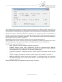
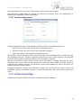
2.6.2 Record Data
To access to the record window click
record data.
on the icon menu on the tool-bar, or go to File→
To record the data from the flight click on Select File and choose a file or create a new one
by writing a new name.
Once a file is selected, click on start button to start recording the flight in the selected file
and stop to finish recording. The recorded flights can be replayed afterward with by
loading the generated file in the Communications dialog (See Section 2.6.1.1.2 Replaying a
flight file).
An alarm, displayed in state window, is linked to the file writer status (See 2.8.5.1 Alarms
section). When recording to a file, REC alarm is green and red when the file writer is not
active.
Figure 13: Record dialog window
2.7 Map Menu
Behaviour of the map is controlled through this menu.
First two entries in the menu are the usual zoom in and
zoom out commands.
Afterward, a Clear Map Trace entry is shown: This will clear
the trailing points the map draw to represent past climb rate.
Figure 14: Map Menu
By activating this entry, previous points will be forgotten and a
new trail will begin to show.
Last section of the menu is a map mode selector:
•
In Map Free you are free to move the map view and inspect whatever you wish.
•
In Plane On Screen the map will re-center on the transmitted position if the actual
position of the aircraft is not in the map view.
•
In Plane On Center the aircraft will remain at all times at the center of the map
view. This option may be heavy in CPU load and battery drain.
2.8 View Menu: Real time information windows
The U-See software have a set of windows that will report information to the user in
real-time, allowing to control the current state of the UAV. These windows are shown
independently to support multi-display environments more comfortably.
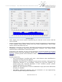
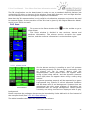
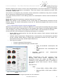
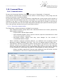
2.8.1 Sensors Summary
In sensors summary windows it's possible to see the real time data received by U-See
concerning the on-board sensors. This window is divided in six windows:
Document Version 1.25
19
U-See User Manual - View Menu: Real time information windows
Figure 15: Sensor summary window display. Barometric Correction, GPS state, GPS
Channels Signal
•
Euler Angles and Vertical Speed: Representing the attitude of the vehicle and the
vertical speed.
•
Internal temperatures: Measurement from the internal temperature sensor/sensors
in the autopilot. Triple sensor version will have three temperatures, while single
sensor version will show only one.
•
Barometric Correction: As an option, autopilot and ground control station exchange
information to establish high precision barometric altimetry. This dialog allows
monitorization of barometric correction status.
Presented in this window, are the current barometric correction applied to on-board
pressure sensor since last reference setting (See Section 2.12.6 Air Data System
Settings), current ground sensed altimeter value in meters and a correction status
description.
Possible status are:
•
OK: Ground Sensor is working well and a valid reference was established so
correction is being correctly applied.
•
BADSENS: Ground Sensor is failing for some reason and thus, high precission
differential altimetry is not available. Should you find this condition, try
power-cycling the U-Ground Hardware. If this condition persist, please,
contact Airelectronics for support.
•
NOREF: No valid reference could be established. High precission differential
altimetry is disabled.
•
NOCONFIG: Differential altimetry was not activated or is not supported by
current autopilot and ground station pair.
Document Version 1.25
20
U-See User Manual - View Menu: Real time information windows
•
EXCESS: Excessive correction detected. If variation since reference was
established surpass a threshold correction is discarded as invalid. This may
be indicative of ground sensor failure. Please, contact Airelectronics for
support in this case.
•
NOTSET: Barometric altimetry has been never been crossed against GPS
measurement in the current autopilot uptime. This is a typical situation
encountered when the system has been powered-on recently and has never
had a valid GPS fix. This implies that current static pressure indication may
be off by several dozen of meters until an altimeter 'set' command is
performed. For this, go to Settings → Air Data system and press the ' Sync GPS
& Altimeter' button. Valid GPS fix is necessary for this to work and the
autopilot will perform automatically a set command when it has GPS fix
calculated with at least 6 satellites.
•
FILT: The Ground Control station indication of pressure have changed too fast
in a very short time and the autopilot is introducing this correction in a
filtered way to avoid sudden changes of altitude. This situation can occur
when recovering contact with an UAV after a long period of communications
blackout. Special attention is required in case this occurs.
•
Position: shows data on GPS solution for current position in the UAV
•
State: shows quality information regarding the fix:
◦ Mode
shows
what
kind
of
solution
Possible modes are: 2D, 3D, DGPS and 'No Fix'.
the
GPS
is
offering.
◦ Satellites show the number of satellites used to produce current navigation fix 10.
◦ Diff Age: Shows how old is the data used for Differential correction
•
U-Ground Position: GPS solution for the position of the Ground Control Station.
•
GPS Channel Info: you will have access to the signal status of the tracking channels
the GPS modules has. Informing you of which satellite the autopilot is tracking to
compute its GPS position and what signal level is receiving from every satellite.
The chart shows the identification of the Space Vehicle being tracked (SV ID). Those
SV identified with numbers above 120 correspond to SBAS 11 systems such as WAAS
or EGNOS.
The chart displays also the signal level. Acceptable signal levels would be over 30
dbHz.
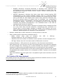
2.8.2 Relative GPS Status (Optional)
This window will be only displayed on moving base operations enabled versions of U-See.
So this section may not apply to your U-See version
10 Do not mistake this number with the number of visible satellites over the horizon.
11 Satellite Based Augmentation Systems
Document Version 1.25
21
U-See User Manual - View Menu: Real time information windows
Figure 16: Relative GPS typical appearance
This window shows information about the current status of the Relative GPS solution. It will
show the baseline distance and the azimuth and elevation of the baseline. Said azimuth
and elevation is measured from geographic north and oriented in the Base-Rover direction.
Below this, there is indication about the quality of the solution by mean of indication of
sigma(σ) value. This value shows the threshold in which a 60% of the measurements given
by the system will be inside that threshold. Fully operational system should give sigmas in
the range of the thousandth of degree.
MasterPOS shows the current GPS solution for the moving base position.
Status shows the kind of solution that is being computed and Operative shoes with a true
or false indication if the system is usable for landing operation in a moving base.
Possible status for the solution are:
•
None: System could not establish relative positioning.
•
PSRDIFF: Solution comes from a differential correction of pseudo-ranges. Relative
positioning obtained using this method is considered not valid for accuracy landings
on moving bases, but could work for stationary approaches.
•
L1_FLOAT: Floating L1 ambiguity solution. Typical sigma of this mode will be around
1°.
•
L1_INT: Integer L1 ambiguity solution. Typical sigma of this mode is around 0.1°
•
NARROW_INTEGER: Carrier phase wave-number is calculated using the maximum
information possible. This is the desired state of functioning and typical sigma can
be as low as 0.001°
Notice possible state are ordered from less to more accurate.
Document Version 1.25
22
U-See User Manual - View Menu: Real time information windows
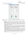
2.8.3 Video Capture (Optional)
Figure 17: Video capture dialog with and withoug advanced options deployed
This is an optional feature and may not apply to your U-See version
U-See optionally supports opening video devices to show video as acquired by the UAV.
Video devices are opened indicating the system integer index. This is a current limitation
we are working to remove, and in the future devices will be referred by name.
First video device connected to the system is index 0, second one is index 1, and so on.
Through open and close button at the top the video feed is enabled or disabled.
The latitude, longitude and elevation shown at the top of the frame are the calculated
positions of the centre of the image. Not the current position of the aircraft. At the bottom
of the frame the distance to the landing site is over-imposed.
Video recording is also available through the buttons at the bottom of the dialog. To start
recording, select a file-name to record to and the encoding facility to be used through the
selector. Available options are:
•
x264: Under windows a vfw filter is necessary to enable this codec
•
h264: Under windows a vfw filter is necessary to enable this codec
•
Raw Video: record raw frames to an avi container.
•
Choose from system codecs: At the time of pressing Rec button a dialog will open
presenting available system codecs to choose. This is only supported in windows. A
known limitation is that sometimes this dialog appears without focus. Click on the
windows taskbar entry to bring it to the front of the windows stack.
Once selected file-name and format, the recording button will be enabled and allow
starting the recording.
While recording, it is possible to dump individual frames as pictures by using the third
button in the bottom row.
Through the button “adv. Options” Brightness, Contrast and Saturation and mirroring
options are exposed.
Document Version 1.25
23
U-See User Manual - View Menu: Real time information windows
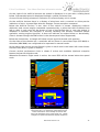
2.8.4 Synthetic View / Artificial Horizon
Go to View → Synthetic View to open the real time synthetic 3D vision.
The 3D view represents the aircraft surroundings with data provided by the Digital
Elevation Model and the landing point location.
Additionally to the 3D environment information, the Synthetic View provides a lot of useful
real time information through a HUD, such as speed, altitude, course or variometer.
Terrain elevation is generated using a Digital Elevation Model (DEM for
short) incorporated into U-See.
Default DEM used in U-See has global coverage but, in exchange, its
accuracy at some points may be lacking. Errors as high as 150 m. can
exist.
'VISUAL' FLIGHT USING THIS VIEW IS STRICTLY FORBIDDEN. Its
accuracy is not enough to keep the plane from running into ground. This view is
supplied only as a way of improving situational awareness of the operator. Not as a tool
to pilot the plane.
This warning still applies if high detail DEM is loaded instead of U-See default: DEMs
usually do NOT include obstacles (as buildings and antennas) and terrain may have
changed since the DEM preparation date by human development.
The HUD also represents the autopilot commanded values in yellow color and the
commanded attitude in purple like a flight director. The variometer on the left side
represents the instant variometer measure with a filled triangle and the filtered value with
an empty one.
On the bottom of the display information about unit being used to present the data is
given.
Information about the visualisation mode and flight mode is represented on the top left
corner and the distance to the landing is placed on the right.
Figure 18: Synthetic 3D View
Figure 19: 2D Artificial Horizon
Document Version 1.25
24
U-See User Manual - View Menu: Real time information windows
The 3D visualization can be deactivated in order to use a standard Artificial Horizon just
unchecking 3D View on the top of the window. Some HUD features, such as flight director
can be switched on and off through its respective checkboxes.
Note that the 3D representation is only valid for visualization purposes and cannot be used
for manual flights, as the precision of the 3D view is given by the Digital Elevation Model,
and it is not 100% accurate.
2.8.5 State
To access to the State window click
View→State.
on the toolbar or go to
The State window is divided in two sections, alarms and
surfaces information. The alarms section occupies the upper
section, and the surfaces information is at the bottom region.
Figure 20: State window
2.8.5.1 Alarms section
On the alarms section is possible to see if all systems
are working properly. To start a flight is necessary that
all alarms are set in green. Notice that the
magnetometer alarm (MAG) does not appear when
using a fixed wing vehicle, and the dynamic pressure
alarm (QD) does not appear when using a rotary wing
vehicle.
Figure 21: Alarms section of the
State Window
background.
A system operating properly will be reported by a green
background. Any system in critical abnormal condition
will be drawn with a red background. Systems that are
operational but with some problem or limitation are
presented with an orange background. Those system
currently not being checked are displayed with a grey
Please note that the voltages alarms may be bounded by limits defined in U-See instead of
the autopilot itself (See 2.12.10 U-See settings ).
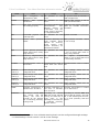
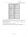
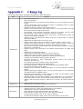
The table hereafter describes the meaning of the alarms.
Document Version 1.25
25
U-See User Manual - View Menu: Real time information windows
Alarm
Green
Orange
Red
GPS
Valid
navigation
obtained from GPS
R-GPS
Relative
GPS
operational
IMU
Gyro and Accelerometer This state indicates that A failure in the sensor suite has
are working properly
measurements
from made the attitude estimation
different sensors are unreliable.
inconsistent
and
the
sensor suite is operating
in a degraded mode.
JOY
Connected Joystick
receiving data.
PS
Correct
values
QD
Correct dynamic pressure Not possible
values (Not used in rotary alarm
wing vehicles)
for
this Static pressure measure failed
or out of range (Not used on
rotary wing vehicles)
MAG
Receiving magnetometer Not possible
signal (Not used on fixed alarm
wing vehicles)
for
this Not
logical
magnetometer
values or out of range (Not used
on fixed wing vehicles)
COMMS
Communications level is Communications level is Communications level is below
above 60%
below 60% but above 40%
40%
Internal
battery 1
ADC1 voltage value within Not possible
configured limits
alarm
for
this ADC1 voltage value
configured limits.
out
of
Internal
battery 2
ADC2 voltage value within Not possible
configured limits
alarm
for
this ADC2 voltage value
configured limits.
out
of
Internal
battery 3
ADC3 voltage value within Not possible
configured limits
alarm
for
this ADC3 voltage value
configured limits.
out
of
Internal
battery 4
ADC4 voltage value within Not possible
configured limits
alarm
for
this ADC4 voltage value
configured limits.
out
of
TEMP
Autopilot temperature is Autopilot is between 0°C Autopilot temperature is below
between 10°C and 60°C
and 10°C or between 0°C or above 70°C
60°C and 70°C
TERRAIN12
According to current DEM
and current UAV 3D
velocity, the next 20
seconds do not present
risk of entering proximity
of the ground
static
fix Not possible
alarm
in
this The system could not calculate a
valid navigation fix.
system Not possible
alarm
in
this Relative GPS system is not in
valid operational state.
and Not possible
alarm
for
this Joystick not found
pressure Barometric altimetry has Static pressure measure
some problem which or out of range
reduces its accuracy.
Check
section
2.8.1
Sensors Summary for
detailed information
According
to
current
DEM and current UAV 3D
velocity, the UAV will, at
some
point
in
the
following 20 seconds, be
in moderate proximity
with the terrain.
failed
According to current DEM and
current UAV 3D velocity, the UAV
will, in the following 20 seconds,
be in close proximity with the
terrain.
12 To define how close is too close, altitude warning levels can be configured through settings
→ U-See Settings. Check section 2.12.10 U-See settings
Document Version 1.25
26
U-See User Manual - View Menu: Real time information windows
Alarm
Green
Orange
specified Not possible
alarm
Red
DIST
UAV is within
distances limits
ENG
Engine is operating within The
Engine
is
limits
operational but some
operation parameter is
in degraded mode.
Check
engine
data
window under view →
engine data for further
info
ARL
(Auto
Return
Limits)
(Note
that
Bingo
time
and COMMs
have
their
own
alarm
and it is not
included
in
this one.)
Some limit for auto-return Not possible
in mission supervisor was alarm
surpassed and a return
home is recommended. 14
for
this Never in the uptime of the autopilot
an
auto-return
home
request has been issued by
mission-supervisor limits.
Bingo time
(2.9.5 Bingo
Time)
Remaining
displayed
time Not possible
alarm
for
this Bingo time exceed “BINGO” is
displayed
Camera
Not possible for this alarm Not possible
Mode.
Text
alarm
will
display
current
mode.
for
this Not possible for this alarm
REC
Recording data
Not possible
alarm
for
this Not recording data
Mode15
Flight mode selected
Reduced control mode Autopilot mode active has very
active.
limited or none control ability
and could cause a crash if
unattended (e.g. Manual mode)
Bingo
for
this UAV is farther than configured
distance limit
Engine is not operational or
some fault is being reported that
severely
compromises
the
continuity of flight.
Also red when, in electric
vehicle,
battery
level
falls
beyond configured limit.13
Check engine data window
under view → engine data for
further info
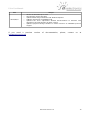
Table 1: Alarm descriptions
13 Check section 2.12.10 U-See settings for details on how to set battery limit for alarm.
14 This feature may be not present in your version of U-See.
15 Check Table 3: Rotary Wing Modes Key and Table 2: Fixed Wing Modes Key. for the meaning
of mode key displayed as text in this alarm
Document Version 1.25
27
U-See User Manual - View Menu: Real time information windows
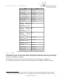
Fixed wing modes
Reported mode in alarms
Meaning
MANUAL
Manual mode
FLYTO
Fly to mode
ROULETTE
Roulette mode
RETURN
Landing mode: Returning
towards the landing field
HOLD
Landing: Hold a circular
pattern to adjust UAV
altitude to a proper value
for final
FINAL
Landing: Executing
approach
FLARE
Landing: executing landing
flare to touch ground
SERVOS
Servo adjustment mode.
LOOPS
Internal Loops mode
ORBITING
Orbit mode, the UAV will
describe circles around a
set point
FPLAN
Flight plan. UAV will follow
flight plan point by point
TAKE-OFF
Take off: UAV is executing a
take-off maneuver.
CATARM
Catapult launch is armed.
Autopilot is waiting to
detect movement to go
into full Take-Off mode.
ABORT
Autopilot is executing a
pre-programmed
abort
manouver.
S-FLYTO / S-ORBIT
Equivalent to FLYTO and
ORBITING but with moving
base support. These modes
will
maintain
relative
geometry to the moving
base.
RET_NET
Landing Mode: Returning
for a net Landing with a
moving base
HOLD_NET
Landing
Mode:
Hold
pattern for net approach
with a moving base
FIN_NET
Landing Mode: On final
approach for net landing
with a moving base.
L-TAKEOFF
Auto-Learn TakeOff: For
hand launched aircrafts.
Document Version 1.25
Final
28
U-See User Manual - View Menu: Real time information windows
Fixed wing modes
Reported mode in alarms
Meaning
Come Above mode: In this
mode the UAV will navigate
to the vertical of the
landing site and start an
orbiting upon arrival.
SAFE-RET
Table 2: Fixed Wing Modes Key.
Modes with yellow background and aircraft-specific modes and may be unavailable for
your U-See version.
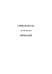
Rotary Wing modes
Reported mode in alarms
Meaning
MANUAL
Manual mode
NAV
UAV will navigate to a set
point and keep a hovering
flight over this point at the
commanded altitude when
arrived.
FPLAN
Flight plan mode.
TAKE-OFF
Take off Mode
LANDING
Landing
progress
SERVOS
The system is in
adjustment mode
ELOOPS
Interal Loops
Maneuver
on
servo
Table 3: Rotary Wing Modes Key
NOTE: Servo adjustment mode and internal loops are not flight modes, and they should
never be commanded during an actual flight.
Camera mode
Meaning
FORW
Forward looking: Camera will look
straight ahead of UAV
MANUAL
Camera will point whatever value
the user has selected
STABILISED
Camera will compensate for attitude
variations of the camera.
GEO
Camera will compensate attitude
changes AND Position changes,
looking to a fixed point on ground
NEUTRAL
Camera actuators are positioned in
neutral state
LATERAL
Special Lateral Mode
Table 4: Camera Modes Available
Document Version 1.25
29
U-See User Manual - View Menu: Real time information windows
2.8.5.2 Surfaces section
On the surfaces section there is information about the
position and command of the UAV.
On the left side the current altitude is displayed into
the white square and the commanded altitude is
represented by a yellow line. In case the commanded
altitude is out of the range displayed at that moment,
a yellow arrow appears on the commanded altitude
direction.
Terrain level according to current loaded DEM is
represented by a solid brown background, and colored
segments on the left side of the altitude scale
represent current selected DEM warning levels.
When supported (optional feature of the autopilot), a
sliding triangle will show on the left margin indicating
altitude the aircraft should be at to comply with the
current vertical performance limit (See 2.10.1.3
Vertical Performance limits)
On the right side of the section, the current speed is
displayed into the white box in the same way as the
altitude, and the commanded speed is represented by a yellow line.
Figure 22: Surfaces section of state
window
On top of both columns an indication showing current display unit is present.
In a rotary wing UAV the commanded speed controls the speed that the vehicle uses to
transition between commanded points. If it is already over the designated point, it will
start a hover, thus its speed will be 0, regardless of the commanded speed, as there is no
need to execute a transition.
On the center of the section there are two screens showing rear and lateral view of the
plane with real time information about its attitude is displayed.
On the upper screen (rear view) the roll position of plane is displayed, and the commanded
roll is represented by a yellow line. On the same screen the commanded surfaces are
represented in yellow. On top of this screen there is a representation of the turn
coordination (ball display).
Whenever the flaps (FLP MAN) or airbrakes (ABK MAN) are configured to be deployed in
manual mode, a reminder will show at the bottom of the rear view.
When active, in the black segment between both views a reminder of current vertical
performance limit will be displayed at the left margin.
If the speed control is adjusted for Economic flight (See 2.10.1.2 Normal and ECO flight
laws), the word ECO will be displayed by the speed rectangle.
On the lower screen (lateral view) the pitch position of plane is displayed, and the
commanded pitch is represented by a yellow line. On the same screen the commanded
surfaces are represented in yellow and the throttle is represented as a yellow bar.
Bellow the throttle bar, a triangle will be displayed. This triangle shows current throttle
stick position in the manual pilot joystick.
Whenever the engine is disabled, a red cross will be displayed over the throttle command.
In the lower right corner ground Speed is given in km/h and in the lower left corner Above
Ground Level (AGL) is given in meters.
Document Version 1.25
30
U-See User Manual - View Menu: Real time information windows
Figure 23: Full symbology display. Note that this is an
artificially generated image. Some indications are
mutually exclusive and won't be displayed at the same
time (e.g. yellow triangles in speed and altitude display
columns)
2.8.5.3 Alternate Surfaces section
Through Settings → Ground Settings a different data
presentation option can be selected. The choice will
we remembered between application sessions.
Unless previous experience with flight indicators,
we don't recommend its usage.
In the alternate representation, the main display is an
artificial horizon (See figure 24) with a display of
surface deflection immediately below.
On the left of the artificial horizon the altitude is
displayed exactly in a box and with a sliding band
below. Commanded altitude is represented through a
horizontal yellow line
Terrain level according to current loaded DEM is
represented by solid brown background, and colored
segments on the right side of the altitude scale
represent current selected DEM warning levels
Figure 24: Alternate data presentation
Document Version 1.25
31
U-See User Manual - View Menu: Real time information windows
On the right of the artificial horizon the speed is displayed in a box with a sliding band
below. Commanded speed is displayed through a yellow horizontal line.
On top of both sliding columns an indication of current display unit is shown.
On the artificial horizon there is a display of wing bars and a crosshair to allow precise
indication of pitch. A green flight director displays current autopilot command.
Below the artificial horizon, a rear view of the vehicle is shown, displaying surfaces
deflection and current engine command represented by a yellow bar that increases from
left to right. A red cross will be drawn on top of the throttle bar in case the engine is
disabled. It indicates the autopilot is actively disabling the throttle command (where
available; cutting engine injection). It does not indicate an engine failure or abnormality
(That is shown through the ENG alarm in the alarms panel when supported).
Below the throttle bar, a triangle will show current joystick throttle stick position.
On the sides of the throttle bar, a reminder will be shown in case either flaps (FLP MAN) or
airbrakes (ABK MAN) are configured to be operated in manual mode.
In the lower right corner ground Speed is given in km/h and in the lower left corner Above
Ground Level (AGL) is given in meters.
Current vertical performance limit is shown if active and available (Optional autopilot
feature) below the altitude scale.
Whenever Economic Flight mode is active, the word ECO will be shown below the speed
scale.
Figure 25: Alternate presentation: Full symbology.
Note that this is an artificially generated image.
Some indications are mutually exclusive and
won't be displayed at the same time (e.g. yellow
triangles in speed and altitude display columns)
Document Version 1.25
32
U-See User Manual - View Menu: Real time information windows
2.8.5.4 Warning about AGL indication
AGL information is calculated using the selected Digital Elevation Model
(DEM for short).
Default DEM used in U-See has global coverage but, in exchange, its
accuracy at some points may be lacking. Errors as high as 150 m. can
exist.
Because of this, we advise to take AGL values with a pinch of salt, and
only for broad informational purposes. Never fully trust this values for in-flight planning.
A Safe terrain clearance should be kept at all times.
This warning still applies if high detail DEM is loaded instead of U-See default: DEMs
usually do NOT include obstacles (as buildings and antennas) and terrain may have
changed since the DEM preparation date because of human development.
2.8.6 Joystick
To access to the Joystick window go to View → JoyStick.
This window provides real time information about the Joystick position in graphical form.
The purpose of this screen is to verify the correct behavior of the Joystick. Check that
movement on the screen is the same than real movement of the sticks on the Futaba
Joystick. In case it is not, change the Futaba settings.
Figure 26: Joystick information
window
The left half represents throttle in the vertical axis and rudder input in the horizontal axis.
The right half represents elevator input in the vertical axis and aileron input in the
horizontal axis.
This axis assignment Is independent of mode (Mode /Mode II) configuration for the actual
joystick.
2.8.7 Engine Data
Accessed through View → Engine Data. This tool is only available for electric vehicles and
monitorized engines (ECU controlled engines)
Document Version 1.25
33
U-See User Manual - View Menu: Real time information windows
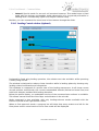
2.8.7.1 Electric engine Data
Figure 27: Engine data window
This menu is divided in two sections:
The Engine data displays, in real-time, the Throttle commanded to the engine, the main
battery voltage, the amperage consumed by the system and the wattage.
As different autopilots have different main battery channel assigments, a drop-down select
box is provided to select the proper main battery channel. This selector affects only the
wattage calculation and the graphical plotter of wattage against IAS.
A real-time plot of the IAS (Indicated Air Speed) of the plane vs the Wattage of the engine
can be shown with the Graphs button on this section. The IAS is shown on the horizontal
axis with unit indication in the right bottom corner while the instantaneous power is shown
on the vertical axis in Watts.
Figure 28:Example of IAS vs Wattage plot
The Battery data section shows data about the battery capacity status: the information
shown corresponds to the mAh left on the battery, and the percentage of battery left. For
that it is necessary to set the maximum battery Amperage on the Max [mAh] box, before
the mission starts. With this data is possible to know the amount of consumed battery with
an error lower than 3%.
Document Version 1.25
34
U-See User Manual - View Menu: Real time information windows
Besides capacity left, there is also a time left estimation. This time estimation is computed
using the displayed estimate consumption. The time shown is the estimate to reach 15%
of battery capacity left.
Old versions of autopilot may not have a time estimation available as they don't transmit
all the necessary information for this estimation.
The reset button present in this dialog resets the consumption counter held on-board the
autopilot.
Note: Notice that the maximum capacity must set be in mAh.
Note: This option is only available for the U-Pilot with an amperometer mounted on the
battery cables. For further information check the 3.2 Monitoring engine data section on the
U-pilot manual.
2.8.7.2 Moscat ME03 electronic injection controlled engine
Whenever the system detects a Moscat ME03 ECU connected and sending data the engine
data window will switch automatically to this display (See Figure 29: Moscat ME03 Engine
control display). Only when connected to this kind of ECU U-See will show this window.
On the left half of the window the following information is available.
•
Engine RPM as measured by the two hall efect sensors: Both sensors should read
very similar rpms.
•
Cylinder head temperature: Temperature as measured by the thermopairs installed
at the cylinder head. While in flight both indications should be very similar. OnGround functioning may exhibit slight differences.
•
Fuel injection status:
•
Current measured fuel pressure
•
Current approximated engine throttle value
•
•
Total accumulated consumption in
kg.16
•
Instantaneous fuel consumption in
kg/h
Manifold
pressure
measurement.
and
temperature
RPMs, Temperature and fuel pressure have
warning and critical values. Whenever the
parameter enters this range, the ENG alarm is
triggered in the appropriate level is launched in
the alarms panel (See Section 2.8.5.1, Alarms
section)
The limits are:
•
Figure 29: Moscat ME03 Engine control
display
RPM:
•
Critical: RPM < 1500 or RPM > 6500
•
Warning: RPM < 1900 rpm or RPM >
6000
16 Current version does not support pounds for fuel indication.
Document Version 1.25
35
U-See User Manual - View Menu: Real time information windows
•
•
Temperature:
•
Critical: Temperature > 200°C
•
Warning: Temperature < 70°C or Temperature > 180°C
Fuel Pressure
•
Nominal value is 2.5 bar
•
Critical: Fuel pressure <1.5 bar or Fuel Pressure > 3.5 bar
•
Warning: Fuel pressure < 2.0 bar or Fuel Pressure > 3.0 bar
On the right half of the window, by order, following information is found:
•
Engine Status. Possible status are:
•
STOPPED: Engine is not working. The word STOPPED will be red coloured and
this state is linked to a critical alarm in the ENG alarm in the alarms panel.
•
CRANKING: Engine is being externally turned. Word will be black-coloured and
this state is linked to warning state of the ENG alarm in the alarms panel.
•
WARMING-UP: Engine has been recently started and it is running an
automatic warm-up cycle. During this time, the autopilot does not have
control over engine RPM and the engine is not ready for flight. This mode will
end as soon the mean of both engine temperature indication reaches 80 °C.
When in this state, the word WARMING-UP will be coloured in orange and this
state is linked to a warning state of the ENG alarm in the alarms panel.
•
RUNNING: Engine is running by its own means and the autopilot has control
over it. In this state, the work RUNNING will be green coloured and, if no
other problem is found in the engine operating parameters, this is linked to a
normal state of the ENG alarm in the alarms panel.
•
ECU working condition information: temperature and main voltage value.
•
Control information: Values the control is trying to maintain. These values and the
measured values should agree.
•
Alarms: This subpanel holds the alarms information regarding engine subsystems.
Any abnormal condition will be signalled by showing the word FAIL coloured in red
and it will trigger a critical alarm state of the alarm ENG in the alarms panel.
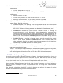
2.8.8 Vibration frequency Graphs
Accessed through View → Vibration Frequency Graphs, this unique functionality allows you
to examine the vibration spectra of your vehicle in real time. With this tool you can clearly
see the source of vibration in your system and check if the system vibration is nominal, or,
on the other hand, there is a new source of vibration indicative of a failure.
In this window you can see the current state of the three axis vibration pattern, with a bar
that scans the different frequencies. On the right hand of every axis you have options to
alter the vertical scale (x2, x1, x1/2, x1/4) that will alter the height of a given vibration
amplitude.
Also, there is a checkbox titled “LPF” 17: with it checked you will see the mean of various
samples and unchecked will give the immediate result.
17 LPF stands for Low Pass Filter
Document Version 1.25
36
U-See User Manual - View Menu: Real time information windows
Figure 30: Vibration frequency Graphs window
2.8.9 Time log
Figure 31: Time log dialog
problems should they arise.
This windows shows current uptime as
registered by the autopilot. This is the time that
has passed since the power-on of the autopilot.
This time is always positive and it is
monotonically increasing. This time counter only
resets at autopilot power-on, so it is an
appropriate way to detect power supply
Take-Off time shows how much time has passed since the last U-See detected
automatic take-off phase.
This means that this time won't be accurate if:
•
The flight is started in manual or semi-manual modes.
•
The take-off occurred while the current U-See instance was not running.
•
Control handover has occurred and a different UAV is being monitored.
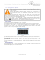
2.9 Pre-Flight Menu
The tools on Pre-Flight drop down menu have to be used before the flight starts, with the
UAV on the Runway, with communication with the U-Ground and with GPS signal.
Safety Warning
It is very recommended to set the manual mode and keep the throttle on
the joystick to minimum while adjusting the pre-flight parameters to
minimize injury risk to persons around the UAV in case the operator makes
a mistake.
It is also very recommendable to keep engines or motors turned off until the UAV is
ready for flight.
Document Version 1.25
37
U-See User Manual - Pre-Flight Menu
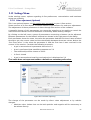
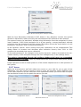
2.9.1 Checklist
The checklist tool allows the user to run a
series of pre-flight checks in order to
prevent errors during operation. The
checklist widget is able to keep in memory
up to 5 pre-designed checklists. The
checklists are defined in text files and can
be provided by Airelectronics or custommade by the client.
The checklist main window allows the user
to add, remove or run up to 5 checklists.
When adding a checklist, the software will
ask the user for the location of the checklist
file and will notify if there are any problems
with the file.
Figure 32: Checklist main window
The checklist files must have the following structure.
First Line: checklist Title
Second Line: creation date (DD/MM/YYYY)
Third Line: author (e.g. Airelectronics)
Fourth Line: BEGIN (checklist start mark)
Next Lines: checklist points, one point per line
Last Line: END (checklist end mark)
Material Skywalker
04/12/2013
Airelectronics
BEGIN
Point 1 to check
Point 2 to check
…
Point N to check
END
Text 1: Example checklist file
When a checklist is successfully loaded, it will appear in the checklist window with the run
button enabled. Clicking this button will start the checklist process asking the user if that is
the correct checklist to run.
During each check of the checklist, the software will block the “Next” button for a few
seconds, preventing the user from skipping points.
Document Version 1.25
38
U-See User Manual - Pre-Flight Menu
Figure 34: Checklist completion
Figure 33: Checklist question
When the checklist is completed, a green tick will appear with a completion message and a
finish button to end the checklist process.
2.9.2 Runway
This tool is used to define the Runway coordinates and altitude. This coordinates can be
entered manually or using the reported GPS position. In both cases the orientation of the
runway must be defined by the operator. When the Runway is set, a runway icon must
appear on the map properly orientated.
To define the Runway follow these steps:
1. Physically place the UAV on the Runway.
2. Check that the GPS signal is correct.
3. Open the Runway window on Pre-Flight → Runway.
4. Click on the radio button to enable the Runway settings.
5. Press the Set current coordinates or introduce manually the latitude, longitude and
altitude.
6. Click the radio button to disable the values introduction and ensure that the
coordinates introduced are correctly set up.
7. Click on the radio button to enable the Runway settings.
8. Select the Heading of the Runway manually.
9. Check that the Runway icon is heading the correct direction on the map.
10. Click on Set button to send the information to the U-Pilot.
Note: In case that the runway settings have to be saved for posterior flights, changes
must be saved on Settings → Save Changes as described in Save Changes section.
2.9.3 Advanced Runway (Optional)
This is an optional feature and may not apply to your U-See version
When available, this dialog allows greater control over the runway location editing process.
This dialogs operates in two modes. Display mode and Editing mode. While in display
mode, the dialog will only display the current stored and reported autopilot values. No
interaction is possible except for clicking the “Enter edit mode” button
Document Version 1.25
39
U-See User Manual - Pre-Flight Menu
While in edit mode, it is possible to hand edit the
landing site coordinates, set the landing site to the
current aircraft position and it is also possible to
select a landing site coordinates by map interaction.
When clicking in “Pick from Map” all dialogs will hide
leaving only map view and a left click on the map will
select those coordinates as landing site. Upon click on
the map, the landing site icon should be displayed on
the clicked position to confirm selection. If not, a click
on set will resend the selected coordinates to the
autopilot.
Figure 35: Advanced Runway dialog in
edit mode
It is important to understand that buttons “Current
coord.” and “Pick from Map” only affects landing site
coordinates, this is, landing site altitude won't be
changed by these buttons and the user must set both
elevation and heading values to appropiate values.
Elevation can be adjusted to current value by clicking “Current” button by the input field or
by writing a value by hand. Current button only affects the landing site elevation
Heading of the landing site can be manually introduced or measured from map through
use of “2Point Pick” button. Click in this button will hide all windows except the map display
and two consecutive left clicks on the map will indicate landing field orientation.
At the bottom of the dialog, above the get and set button a check-box allows to change
the direction the autopilot executes the landing hold orbit. Note that this only affects fixed
wing aircrafts.
At the bottom of the window the usual get and set buttons will put current autopilot values
into the dialog (Get button) or send the current values to the autopilot(Set button)
Safety Warning
Before exiting edit mode verify that the values on-board the autopilot
match the values shown on the dialog by clicking “Get” button and
reviewing the values.
Check that all the necessary parameters have been edited: coordinates,
elevation and heading of the landing site.
2.9.4 Flight-Plan
To open the Flight Plan window go to Pre-Flight → Flight Plan.
In Flight-plan mode the UAV heads one by one to the defined waypoints. These waypoints
are numbered starting with number one. When the last point is reached, the UAV will start
the flight plan again from the first point.
Through the menu entry, access is gained to the flight-plan editor.
This flight-plan editor shows and modifies the contents of a
Autopilot's memory loaded flight-plan. It will not work at all if there
is no communications established with an operating autopilot.
Off-line flight-plan editor is in the works.
Document Version 1.25
40
U-See User Manual - Pre-Flight Menu
When activating “Save Changes” option the active flight-plan is saved into the non-volatile
memory of the autopilot and will be available through power cycling.
Flight-plans can also be saved in a “.fp” file using the “Save to a file” option available in
the flight-plan editor.
Figure 36: Map display during FLY-TO mode with a flight plan ready to activate
Document Version 1.25
41
U-See User Manual - Pre-Flight Menu
2.9.4.1 Flightplan Editor Window. Display Mode
The flight-plan editor window has three well
separated zones:
•
Header of the window: Gives general
information about the current flightplan.
◦ Total Distance: On-Ground distance
the UAV will have traveled after
completing one flight-plan loop
(From point one to the last enabled
point and back to one)
◦ Minimum
Ground
Clearance:
Minimum ground clearance at the
way-points18
Figure 37: Flight-Plan Editor
•
Body of the window: Current way-points
location in coordinates and altitude.
•
Footer of window:
◦ Add a new point at the end of flight-
plan
◦ Save to a file current flight-plan
Every row in the body of the window represents one way-point. Besides its coordinates,
three buttons are available for every row:
•
Get Button: This will query the autopilot for the current values for the way-point.
This is usually not required, as autopilot reports sequentially the current state of the
way-points automatically.
•
Delete Button: This button will delete the selected point and all the following waypoints from the flight-plan
•
Edit Button: This will put the row in edit
mode, changing the way the right click
behaves in the map and allowing
changes in the way-point data.
2.9.4.2 Flight-plan editor: Edit mode
When in edit mode, the looks and behavior of
the flight-plan editor will change:
Notice how all the rows except the one
corresponding point 3 in figure 42 are grayed
out, with their buttons disabled.
Also note that the coordinates and altitude
field in the row for point id 3 are now editable
fields.
Figure 38: Flight-plan editor with point ID 3 in
edit mode
Also, while in edit mode, all the windows in the
program but the flight-plan editor will hide to
allow clear view of the map. Right button click
18 Note that less ground separation could be found in-between points.
Document Version 1.25
42
U-See User Manual - Pre-Flight Menu
will pick coordinates from the map for Point ID 3 position. This change in behavior is shown
on the map with a cursor in crosshair form and a tool-tip reading “Right Click Picks ID Point
X”
To make changes, edit using the keyboard the coordinates and altitude and click Set.
When using the mouse to select coordinates the Set button will be automatically engaged
after each click. Remember to adjust the altitude when operating with the mouse
Get button will put into the editable fields the current autopilot values for the way-point.
Set button will try to upload way-point data to the autopilot and Exit will exit the edit
mode.
After every 'Set' or right click in edit mode, the icon displaying the point on the map should
have moved to the desired position. If not, just push 'Set' repeatedly until the point is in
position.
Closing the Flight-plan window also exits editing mode.
2.9.4.3 New Point Loading
To add a point to the flight-plan click on “New Point”. All windows but the map view will
hide temporarily and the cursor will turn into a crosshair. A tool-tip will follow the cursor to
remind the change of behavior in the right mouse click. It reads “Right button appends
new ID Point X. Altitude will default to maintain ground clearance”
After a right click in the desired position, a new point, with incremental ID should be drawn
on map and reported in the flight-plan window.
Altitude of said point will be the elevation calculated for those coordinates plus the
minimum previous ground clearance. If that's not the desired altitude, it should be edited
using the “Edit” button
Pressing ESC key in the keyboard while in the new point mode will cancel the operation.
2.9.4.4 Completely new flight-plan procedure
For creating a completely new flight-plan follow the following steps:
1. If a previous flight-plan is present: click on “Delete” button for the point ID 1.
2. Click in “Add New Point”
3. Right click in the map for desired way-point position
4. If altitude is not the desired:
1. click in Edit
2. Change altitude
3. Click in Set
4. Confirm altitude by clicking in Get
5. Click in Exit
5. Repeat 2 through 4 until desired flight-plan is ready.
Note that the flight-plan editor will respect the minimum ground clearance, so for a
constant AGL altitude flight-plan the operation will be considerably simplified:
1. If a previous flight-plan is present: click on “Delete” button for the point ID 1.
2. Click in “Add New Point”
3. Adjust altitude to provide desired clearance in point 1
Document Version 1.25
43
U-See User Manual - Pre-Flight Menu
4. Just add following points without worrying about altitude.
Note: Flight Plan points are edited one at a time. This way it is easier to upload and
download the information and the communications are not overloaded.
Note: The Flight Plan points must start on number one. The following flight points must
increase its number by one each time.
Note: If the flight plan created must be saved for posterior flights, the changes must be
saved on Settings → Save Changes as described on 8.7.4 Save Changes.
2.9.5 Bingo Time
Bingo19 time is a prefixed amount of time, that once surpassed will trigger a return home in
the autopilot.
To define this time, select Preflight → Bingo Time. In the dialog, enter the desired amount
of time and the unit this time is expressed in (See Figure 39: Bingo time window) from the
drop down menu and click on Set.
When the bingo time is set, an automatic bingo count down appears on the Bingo alarm on
the Alarm window (See 2.8.5.1 Alarms section )set as green. In case the bingo time arrives
to zero, the bingo alarm will change to red with the word “BINGO” on it.
The operator can override this return home by commanding any other mode, however,
have in mind that until the Bingo time counter is reset, U-Pilot won't attempt another
automatic return home once it has been over-commanded.
A click in Disable Bingo will stop the count-down, disarm the BINGO alarm and deactivate
auto-return home by time.
This tool is not mandatory for flight but recommended.
Figure 39: Bingo time window
2.9.6 Pattern Generator
This tool is intended for use with terrain
observation flights that require covering
some part of the terrain in an exhaustive
manner. By declaring (through right click) the
external outline of the desired surveyed
terrain this tool will generate a set of files
describing the proper pattern flight-plan to
cover the terrain.
2.9.6.1 Intended use
Figure 40: Pattern Generator opened with a
declared field for survey.
Unlike the usual tools included in U-See, this
part of the program does not require a
connected autopilot. We recommend to use
this tool before deploying to the field, leaving
the files prepared for upload once ready for
operation.
19 Bingo is the code word used in OTAN standard radio brevity code to indicate fuel levels
on-board have reached levels that recommend a return to the base.
Document Version 1.25
44
U-See User Manual - Pre-Flight Menu
2.9.6.2 Use of pattern generator
To access pattern generator, select Pre-Flight → Pattern Generator. The pattern geneerator
window will open and the right button click on map will change functionality.
The basics of the pattern generation is the marking of
the desired observation field.
This is accomplished by means of right mouse button
clicks. Every time a right click is made, a vertex is
added to the observation polygon. As many as
needed vertices can be added to the polygon,
although it is necessary to add the vertices in order to
avoid self intersecting polygons.
Polygon will be drawn once you have more than three
points marked and it will get updated while points are
added. Desired survey polygon will be drawn using
intense translucid green color. Save area will be
drawn in a darker green color and projected
navigation legs will be drawn as black lines.
If an error is made, the clear button will clear the
points defined up to the moment and will reset the
area to start again.
Figure 41: Pattern Generator Window
2.9.6.3 Available parameters.
Once declared the desired survey field, a handful of parameters can be adjusted to finetune the generated flight-plan.
•
•
Save Area: UAV needs a non-negible space for making turns, this means that the
final and starting parts of every navigation leg would received bad coverage by the
cameras on-board as the UAV is still trying to manoeuvre to get into position. Save
area parameters controls a grow in the area surveyed to assure the UAV is well
stablished on navigation leg when it reaches the area of interest.
Offset: This parameter controls the lateral separation of the navigation legs.
•
Orientation: It controls the geograhic bearing that will be used to fly over the
disgnated survey area.
•
Altitude: How high the overfly will be made. There are two modes for generating the
flight-plan point altitudes:
◦ Above Seal Level
◦ Above the terrain.
The “Resulting flight plan” informational display shows how many flight-plan points will be
needed for covering the desired field, how many flight-plan files the tool will generate and
the lateral separation of navigational legs in meters
Zoom level of the map will affect the effective lateral separation of the navigation leg
generated. This is because the tool works on screen coordinates and generates
geographic coordinates when writing to file.
Document Version 1.25
45
U-See User Manual - Pre-Flight Menu
AGL information is calculated using a Digital Elevation Model (DEM for
short) incorporated into U-See.
Default DEM used in U-See has global coverage but, in exchange, its
accuracy at some points may be lacking. Errors as high as 150 m. can
exist.
Because of this, we advise to review carefully the generated flight-plan
once it is loaded in the autopilot for proper ground clearance.
This warning still applies if high detail DEM is loaded instead of U-See default: DEMs
usually do NOT include obstacles (as buildings and antennas) and terrain may have
changed since the DEM preparation date because of human development.
2.9.6.4 Saving results
Once the parameters have been adjusted, it is necessary to save the results to disk for
later usage. Such thing is accomplished by clicking on “Save” button. A dialog will open in
which a base name and location should be given for the flight-plan files.
The name given in the dialog will be suffixed with a sequence number and the “.fp” file
extension.
For instance, if a particular area defined needs 67 flight-plan points and the filename given
is “example” the program will save in the selected directory the following files:
•
example-01.fp (Containing flight-plan points 1 to 32)
•
example-02.fp (Containing flight-plan points from 33 to 64)
•
example-03.fp (Containing flight-plan from 65 to 67)
These files should be loaded on the autopilot using the “Flightplan from File” found in the
pre-flight menu. (See following section)
2.9.7 Flightplan From File
Figure 42: Flight-plan Load from file window
This dialog will allow the selection of a “.fp” flight-plan definition file and upload it to an
active connected U-Pilot autopilot.
Once the button start is clicked, the program will check the syntax of the file and will start
uploading the flight-plan points information one by one.
If any problem shall arise during the upload, an informational dialog will be presented
informing the nature of the failure and the proper corrective action to take.
Document Version 1.25
46
U-See User Manual - Command Menu
2.10 Command Menu
2.10.1 Command window
To open the Command window click
icon or go to Command → Command.
The software automatically recognize if the vehicle is fixed wing or rotary wing and will
present the proper command window.
On the main map screen, all the information regarding the current mode will be shown in
green and all the information that the current mode is not using will be shown in blue. For
example if the UAV is in Take-Off mode, the flight plan path will be shown in blue but as
soon as the operator will click the Flight Plan button the flight plan path will become green.
This is the primary window during an actual flight mission.
2.10.1.1 Fixed wing command window
The fixed wing command window is divided in two groups
–
The command modes group where the command buttons are shown, grouped by
flight modes categories:
–
Flight modes: Normal flight modes
–
Special Modes: Modes used in special vehicles, special circumstances or used
only in very specific moments.
–
Non-Flight modes: Modes that may pose danger for the aircraft if
commanded while in-flight.
–
When available (optional Autopilot feature), an aditional row of buttons will be
displayed, reading “NORMAL” and “ECO”. See 2.10.1.2 Normal and ECO flight laws.
–
The Altitude, Velocity and Orbiting radius setting menu. The operator can select the
Altitude, Velocity and Orbiting radius on each flight mode. To do so the operator
must enter the new values on the corresponding box and click Set button. Orbiting
is only available for fixed wing UAVs and it is not available for rotary wing UAVs
–
When available (optional AP feature) and additional item will show: Vertical
Performance. See 2.10.1.3 Vertical Performance limits.
Figure 43: Command window
Document Version 1.25
47
U-See User Manual - Command Menu
Note: Each UAV has a flight envelope which restricts flight speed commands to minimum
and maximum values. Values out of this restriction are not accepted by the U-Pilot. Flight
envelopes may change for each flight mode and are pre-configured by Airelectronics, the
end user does not have to worry about it.
2.10.1.2 Normal and ECO flight laws
Optionally available for fixed wing vehicles only, it is possible to change the speed and
altitude holding strategy. This settings is independent of flight mode, but not all modes
allow command of Economic flight law. Whenever the user changes the mode, the flight
law will reset to normal.
Current flight law will be indicated by a blue background in the currently active flight law
button. Modes that do not accept change of flight law will have both buttons disabled.
Economic flight law will introduce a strategy in which speed is controlled by pitch angle
and altitude is controlled by throttle command. This will reduce altitude holding accuracy,
but, in exchange, throttle command will be executed much more slower.
Additionally, autopilot will not correct altitude errors in the positive, i.e. if the autopilot is
higher than commanded the throttle will be cut to reduce consumption, but not further
action will be taken.
Economic flight also enables gliding navigation and thermal soaring through the orbiting
mode combined with economic flight law.
However, as the altitude control is not as accurate, it should not be activated whenever
near the ground or when flying in airspace that requires strict vertical separation levels.
2.10.1.3 Vertical Performance limits
Optionally available autopilot feature. It may not apply to your software/autopilot pair.
Through this setting, vertical transition climb and descend can be limited. Current limit is
displayed in the selected vertical climb units or “Unlimited” is shown.
When operating unlimited or with a too high limit, the autopilot flight envelope limitations
still apply and transitions will be executed at maximum pre-configured safe values.
2.10.1.4 Available Fixed Wing Modes description
2.10.1.4.1
Manual mode
At this flight mode U-Pilot gives all the control to the external pilot.
This mode must be selected before the mission starts in order to do the Pre-Flight settings.
Be aware of the throttle stick specially in electric motors.
2.10.1.4.2
Semi-Manual
In this mode the manual pilot input commands will be interpreted as requested attitude
angle, instead of requested surface deflection. Autopilot will only control attitude
angles while in this mode, so it is responsibility of the manual pilot to maintain safe
altitude, safe flight speed and proper navigation.
2.10.1.4.3
Fly To mode
At this flight mode the UAV heads a destination point selected by the Computer Operator,
the destination point can be changed on real time just right clicking on the map.
Have in mind that if you have the “Flight plan editor” window opened, the right click will
be associated to flight plan waypoint set, and it won't change the Fly To point (indicated on
the map with a circle with “DP” in it).
When the destination point is reached the UAV automatically goes to orbiting mode using
the destination point as orbiting point.
Document Version 1.25
48
U-See User Manual - Command Menu
In this mode is possible for the Computer Operator to set the commanded orbiting radius,
the commanded speed and the commanded altitude. To define new values of altitude,
speed or radius it is required to write the new value on the corresponding box and then
click Set button.
2.10.1.4.4
Orbiting mode
At this flight mode the UAV orbits a the current position, it will use the current point as
orbiting point.
In this mode is possible for the Computer Operator to set the commanded orbiting radius,
the commanded speed and the commanded altitude. To define new values of altitude,
speed or radius it is required to write the new value on the corresponding box and then
click Set button.
If the computer operator click with the right button on the map, the UAV will orbit around
the point he has clicked. If it turned out that this new point is too far away, the system will
change its mode into Fly to mode, and again, will switch into Orbiting mode when close
enough.
2.10.1.4.5
Landing mode
The UAV changes its mode to landing in three cases:
–
The Computer Operator clicks on Landing Button.
–
The Preflight Bingo Time is reached.
–
There is a Communication failure between the U-Ground and U-Pilot.
It is mandatory to properly set the Runway checking its altitude and Heading before
taking-off. In case of a communication failure the UAV will automatically go to this point.
The landing path is automatically recalculated with all the parameters set to the UAV
requirements, the user do not have to worry about it.
Landing path has 4 stages. The UAV will go through this sequence automatically:
–
Return. The UAV flys towards the hold center point, designated “L” on map. Related
to the runway this point is located backward to the right.
–
Hold. The UAV starts an orbiting mode where adapts its velocity and altitude to
start the final landing part. The UAV will turn this path as many times as necessary
until it is ready to start the Final path. This turn is done by default clockwise, but
turn direction can be adjusted through the advanced runway menu (see 2.9.3
Advanced Runway (Optional))
–
Final. When the UAV trajectory reaches the tangent direction to the Runway the
UAV checks the speed and altitude and if they are correct it will start the final
landing part. It will start decreasing its altitude until it is over the threshold of the
runway
–
Flare. Once the Runway threshold is reached, the UAV will carefully rotate to pitch
up and it will cut down the throttle, in this controlled position it will touch the
ground.
2.10.1.4.6
Roulette mode
On Roulette mode the UAV roll is controlled by the External Pilot with a roulette on the top
right of the Futaba Joystick.
The U-Pilot still controls the altitude and speed. The Computer Operator can command a
new altitude or speed.
Document Version 1.25
49
U-See User Manual - Command Menu
2.10.1.4.7
Flight Plan mode
On this mode the UAV heads one by one different defined points. These points are
numbered starting with number one, when the last point is reached the UAV will start the
flight plan again from the first point.
Each point is defined by its coordinates and by its altitude.
It is better to establish the flight plan before the mission start, but it is possible to edit it
during the flight.
To change these points follow the same procedure described on section 2.9.4 Flight-Plan
2.10.1.4.8
Take-Off mode
On Take-Off mode the UAV starts the take-off maneuver at maximum throttle and
increases the altitude.
The take-off heading is set by the operator on the Runway Heading.
Once the UAV reaches a safe altitude the Computer Operator can change its mode.
Default Autopilot version will not end Take-Off phase until
told so by the operator with a mode change.
Automatic end of Take-Off is an optional feature that has to
be enabled by Airelectronics's upon request. Contact us for
information.
Until a valid GPS fix has been established it is not recommended to start the flight.
2.10.1.4.9
Catapult Armed mode
This mode prepares the aircraft for a catapult-driven take-off. Aircraft will try to maintain
wing level and pre-configured pitch angle during launch. This mode will not command
throttle until a pre-configured amount of time has passed with movement being detected.
This allows bungee launching of electric UAVs without harm for propeller damage to the
person launching the plane.
2.10.1.4.10 Net landing mode
Net landing is a special mode, so it may not be available for your Software/autopilot
version.
Commands the autopilot to land using net recovery mode in moving base mode. The
aircraft will cycle through the same stages that for conventional landing: Return, holding
and final, but the final target will the net location as indicated by the moving base antena.
Vertical offset of the target has to be established through the “ Gains adjustment” setting
entry (See 2.12.1 Gains adjustment (Optional)).
In case the net threshold is crossed and the vehicle has not stopped, autopilot will execute
ABORT manoeuvre automatically.
This mode may not be available in your software version.
2.10.1.4.11 Abort
Execute pre-programmed net landing approach manoeuvre. Parameters of the manoeuvre
are adjusted using the “Gains adjustment” setting entry (See 2.12.1 Gains adjustment
(Optional)). It may not be available for your version.
2.10.1.4.12 S-FlyTo (Subordinate fly-to)
Equivalent to conventional fly-to, but destination point will be continuously automatically
updated to maintain relative geometry to the moving base. This mode may not be
available in your software version.
Document Version 1.25
50
U-See User Manual - Command Menu
2.10.1.4.13 L-TAKEOFF (Learning Take-Off)
Only available for hand-launched aircrafts. Equivalent to normal take-off, but this mode will
set the landing site position, elevation and heading to the point and direction in which the
operator initially launches the aircraft. This mode may not be available in your software
version.
2.10.1.4.14 Come Above
Commands a return to the vertical of the landing site and an orbit upon arrival. If the
commanded altitude is lower than initial approach altitude, autopilot will climb at least
until this altitude. This mode may not be available in your software version.
2.10.1.4.15 Servos Adjustment mode
This mode is used to adjust the mechanical maximum, minimum and neutral position of
the servos. It is detailed on Servos. This mode must not be commanded in flight as the
servos are effectively disconnected from the autopilot.
2.10.1.4.16 Internal Loops mode
This mode is used to test autopilot reaction to change in attitude and proper surface
functioning. U-Pilot will deflect the surfaces trying to maintain pitch 0 and roll 0. This mode
does not run the engine (Unless told so by the manual override in the futaba joystick) and
can be used for pre-flight aircraft check. This mode must not be commanded in flight as it
lacks navigation, speed and altitude control.
2.10.1.5 Rotary wing Command Window
To open the Command window click
icon or go to Command → Command.
The rotary wing command window is divided in two groups
–
The command modes group where the command buttons are shown, the user can
set the current flight mode.
–
The Altitude and Speed setting groups. Current and commanded values are
displayed here. Besides, an input box is displayed to set new commanded values. To
do so, write a new value and push Set. Written value should be displayed now in the
commanded display Notice the lack of orbiting radius command, as it is not used in
rotary wing aircrafts.
Figure 44: Command window when controlling a rotary window
Document Version 1.25
51
U-See User Manual - Command Menu
Note: Each UAV has a flight envelope which restricts flight speed commands to be bound
between a minimum and maximum value. Values out of this restriction are not accepted
by the U-Pilot Autopilot. Flight envelopes may change for each flight mode and are preconfigured by Airelectronics, the end user does not have to worry about it.
2.10.1.6 Available modes for the Rotary Wing UAVs
We recommend you to take a look at our “Video Tutorials” section in our web page
(www.airelectronics.es) to see the system working and to better understand available
modes.
2.10.1.6.1
Manual mode
In this flight mode the U-Pilot Autopilot gives control to the external pilot but still assists
the external pilot, specially with the heading of the UAV, acting as an advanced gyroscope,
making the system more controllable for a human operator.
This mode must be selected before the mission starts in order to do the Pre-Flight settings.
Be aware of the throttle stick specially in electric motors.
The external pilot can always command Manual mode by setting the Futaba Joystick Switch
B to “Switch Down position”. This switch is located on the top left of the Joystick., this will
overrun any mode change from the Computer Operator.
The U-Pilot Autopilot will rest in Manual mode and it will not be possible to change it until
the Switch B will be moved to “Switch Up position”
2.10.1.6.2
Take-Off mode
On Take-Off mode the UAV will start climbing and it will increase the altitude at a specified
preset vertical speed.
The take-off heading is set by the operator on the Runway Heading.
Once the UAV reaches a safe altitude it will automatically switch to Navigation mode.
Until a valid GPS fix has been stablished it is not recommended to start flying.
Just before commanding Take-Off mode the External Pilot must move the throttle stick of
the Futaba joystick up until the UAV is almost flying, then the Computer Operator will click
on Take-Off button. (Leave the throttle stick in that position until the Landing is over)
2.10.1.6.3
Navigation mode
On this flight mode the UAV keeps its position and altitude at a destination point. The
destination point can be changed on real time just right clicking on the map. When the
destination point is reached the UAV keeps this position.
In this mode is possible for the Computer Operator to set the commanded speed and the
commanded altitude. To define new values of altitude or speed it is required to write the
new value on the corresponding box and then click Set button.
Notice than if the commanded speed is equal to 0 the UAV will not change its position.
2.10.1.6.4
Flight Plan mode
On this mode the UAV heads one by one different defined points. These points are
numbered starting with number one, when the last point is reached the UAV will start the
flight plan again from the first point.
Each point is defined by its coordinates and by its altitude.
It is better to stablish the flight plan before the mission start, but it is possible to
determine it during the flight or even to edit, delete or add points.
To change these points follow the same procedure described on section 7.3.6 Flight Plan
Document Version 1.25
52
U-See User Manual - Command Menu
2.10.1.6.5
Landing mode
The UAV changes its mode to landing in three cases:
–
The Computer Operator clicks on Landing Button.
–
The Preflight Bingo Time is reached.
–
There is a Communication failure between the U-Ground and the U-Pilot Autopilot.
It is mandatory to properly set the Runway checking its altitude and Heading before
taking-off. In case of a communication failure the UAV will automatically go to this point.
The landing path is automatically recalculated with all the parameters set to the UAV
requirements, the end user do not have to worry about it.
The UAV will return to the Runway Point at a safe altitude, once this point is reached, it will
command UAV commanded yaw equal to the Runway Heading and it will start descending
at a controlled rate.
Once the Ground has been reached and the UAV has landed, the External Pilot must kill the
engine and then move the B switch to down position, taking control in Manual mode and
then disconnecting power.
2.10.1.6.6
Servos Adjustment mode
This mode is used to adjust the mechanical maximum minimum and neutral position of the
servos. It is detailed in Servos section.
This mode shall never be commanded while in flight, as it disconnects servos from the
autopilot control.
Document Version 1.25
53
U-See User Manual - Command Menu
2.10.2 Camera command window
Figure 45: Camera modes dialog
In this window you can command the available on-board camera pointing capabilities of
U-See.
In this window you can command the different modes available for the camera pointing:
•
Forward: Camera will point directly forward. No change in orientation is permitted
•
Manual: The camera can be adjusted to whatever Pan and Tilt you wish through
the text editing boxes. Camera will point in this direction regardless the vehicle
orientation. The orientation of the camera may be changed in this mode through a
dedicated joystick connected to the computer or entering directly the desired pan
and tilt value in the input boxes.
•
Stabilised: The camera will maintain spatial orientation of the current selected pan
and tilt. If the vehicle rises its nose, the camera will correct the movement to
continuing looking at the same spatial direction. Although it will not follow a
particular sub-vehicle point. The orientation of the camera may be changed in this
mode through a dedicated joystick connected to the computer.
•
Geo-Referenced: In this mode the camera of the vehicle will be pointed towards
the point designated through left click on the map. The camera will correct attitude
changes and position changes in the vehicle to always look to the coordinates
selected. The hardware will use a Digital Elevation Model (DEM) to keep track of the
ground while climbing or descending. The orientation of the camera may be
changed in this mode through a dedicated joystick connected to the computer.
•
Neutral: Camera actuators will be instructed to adopt their neutral position.
Document Version 1.25
54
U-See User Manual - Command Menu
•
Lateral: Special mode for one-axis roll mounted cameras. This mode keeps a fixed
angle with the horizon and enables stable observation of a on-ground point while in
orbiting with a considerably lighter and simpler camera setup.
Besides, you can command the zoom level of the camera through the slider.
2.10.3 Landing Control window (Optional)
Figure 46: Landing Control window
Designed for fixed wing landing operation, this window won't be available. while operating
a rotary wing aircraft.
The window is designed to reduce clutter interface while in landing phase by showing only
landing related commands and information.
This windows is composed of a profile view of the landing manoeuvre. It will show current
aircraft position and altitude, the current commanded altitude (Yellow horizontal line) and
hold level altitude, besides field landing elevation.
Below the profile display, an embedded version of the command aux surfaces is available.
This allows manual override of the flaps and airbrakes in the aircraft.
Mode command is also available, with only landing-relevant modes available with the
buttons located at the right bottom corner.
When in final approach mode, a progress bar will show how many meters are left for the
flare phase and an extra button to force flare mode will be displayed.
Document Version 1.25
55
U-See User Manual - Command Menu
2.10.4 Command Aux Surfaces
U-pilot has its own algorithms to control the flaps and spoilers during the take-off and
landing. There is also a U-Pilot available configuration in witch flaps are controlled
manually by the operator, in that case the flaps must be controlled using the Command
Aux Surfaces window on Command → Command Aux Surfaces. On that windows there are
tree possible flap positions to be chosen by the operator at any time.
From this window, the user can also handle airbrakes adjusting its position or leave them
in automatic for the autopilot to control.
Selecting any other position than “Auto Airbrake” will force the airbrakes to remain in that
position and autopilot won't change its position under any circumstance. Under normal
operating conditions, airbrakes should remain in automatic position.
Figure 47:Command Aux Surfaces window
2.10.5 Engine management
Engine management window offers the possibility to inhibit the engine of the UAV. While
being active, this option ensures that the autopilot (which is constantly controlling the
engine) does not start the engine.
Figure 48: Engine management window
The inhibit feature is intended to be used while UAV is on ground, in the pre-flight phase,
while checking everything is correct. This option should be deactivated before flight
begins.
Activating or deactivating the inhibit option is dangerous
while in flight phase, therefore this option must NOT be
used once UAV is flying.
Document Version 1.25
56
U-See User Manual - Command Menu
If you wish to know if your autopilot supports this additional feature, please check your
autopilot version or contact us.
2.11 Post-Flight Menu
This menu contain options to analyze the data collected from an actual flight. The
operations contained in this section do not require communication to a U-Pilot
2.11.1 Record Data → .txt
Figure 49: Recorded data->.txt Window
This window is used to transform the binary-only telemetry files recorded on the Record
Data dialog to different (usually) text-based formats.
The window presents a button for selecting a binary telemetry file and an output format
selector.
Once the Start button has been clicked, the conversion will start converting the file to the
selected format. The text-version file will be located in the same directory than the
selected binary file, so it is necessary that the file is located in a write-accessible location.
2.11.1.1 Current available formats:
2.11.1.1.1
Aircraft Telemetry TXT
This format exposes the main variables of the flight in a text file suitable for analysis with
Microsoft Excel, LibreOffice/OpenOffice Calc, Matlab and similar.
The filename will be that of the binary telemetry file appended with “.txt”
The information contained into this file is structured in 20 columns, separated by tabulator
character and end of line is marked using \r\n special characters, according to this table:
Document Version 1.25
57
U-See User Manual - Post-Flight Menu
Data
Units
Pitch
[Degrees]
Roll
[Degrees]
Yaw
[Degrees]
Commanded Pitch
[Degrees]
Commanded Roll
[Degrees]
Commanded Yaw
[Degrees]
ADC Channel 1
[Volts]
ADC Channel 2
[Volts]
ADC Channel 3
[Volts]
ADC Channel 4
[Volts]
Altitude
[meters]
latitude
[Degrees]
longitude
[Degrees]
IAS
[km/h]
Ground Speed
[km/h]
Commanded IAS
[km/h]
Commanded Altitude
[m]
Speed North
[km/h]
Speed East
[km/h]
Speed Down
[km/h]
Table 5: Data exported for analysis available to the end user
2.11.1.1.2
Camera shots position file TXT
This expansion format is intended for post-process of topography and agriculture studies
flights. It will export the main information regarding camera shoots coordinates, plane
attitude and time of the shoot.
The filename will be
“_Pointing_coordinates.txt”
that
of
the
binary
telemetry
file
appended
with
Every line in the file is the position of a camera shoot.
The information contained into this file is structured in 18 columns, separated by tabulator
character according to the table 6. End of line is marked by \r\n special characters.
Document Version 1.25
58
U-See User Manual - Post-Flight Menu
Data
Units
Aircraft Pitch
[Degrees]
Aircraft Roll
[Degrees]
Aircraft Yaw
[Degrees]
Aircraft Latitude
[Degrees]
Aircraft Longitude
[Degrees]
Aircraft Altitude
[Meters]
Camera Pan
[Degrees]
Camera Tilt
[Degrees]
Camera
normalized [0-1]
pointing
vector
in
horizontal
frame.
North component.
Camera
normalized [0-1]
pointing
vector
in
horizontal
frame.
East component.
Camera
normalized [0-1]
pointing
vector
in
horizontal
frame.
Down component.
Camera
Pointing [Degrees]
target Latitude
Camera
Pointing [Degrees]
target Longitude
Camera
pointing [Meters]
target elevation.
UTC_hour
[Hours]
UTC_minutes
[Minutes]
UTC_seconds
[Seconds]
20
[seconds]
TimeStamp
Table 6: Data exported for analysis available to the end user
2.11.1.1.3
NMEA
Telemetry file will be converted to standard NMEA 0803 message lines. Due to limitations
in the NMEA protocol for UAV applications, only position information will be written through
$GPGLL and $GPGGA messages.
The filename will be that of the binary telemetry file appended with “_NMEA.txt”
For information about the structure of these message, check NMEA 0183 specification
20 This is the uptime value (See section 2.8.9 Time log) of the autopilot when the photo was
taken. Its resolution is about 1 ms, so it should be much more accurate than UTC_seconds.
Document Version 1.25
59
U-See User Manual - Settings Menu
2.12 Settings Menu
Under settings menu, options regarding U-See preferences, customization and hardware
setup are available.
2.12.1 Gains adjustment (Optional)
This is an optional feature, so this section may not apply to your U-See version
Some versions of U-See expose a limited amount of parameters for end-user adjustment.
The adjustment of these parameters is done through this section of the software.
A wrongful change of this parameters can cause the autopilot to be unable to control the
vehicle and the utmost care and attention is necessary when making changes.
By clicking on the left icons a group of parameters concerning a feature can be adjusted.
Relevant parameters for the feature selected are shown in the right pane of the dialog.
Each parameter shows its name, the value the parameter had the first time it was received
through a get, the current value and the relationship between those two values. Notice the
“first time value” is the value the parameter it had the first time it was received in the
current U-See session. Consider the following sceneario:
•
A get is executed and a parameter has value 1.0
•
A set is performed that establish parameter as 2.0
•
The relationship will be shown as 200%
•
U-See is closed
•
A get is executed and now first received value is displayed as 2.0
First value does not represent neither a default nor necessary safe value.
Figure 50: Parameter adjusting
The change of the parameter can be made by direct value adjustment or by relative
changes.
•
Absolute value: Values that can be both positive and negative will be necessary to
be written directly.
Document Version 1.25
60
U-See User Manual - Settings Menu
•
Relative: Values that do not need to change sign will be adjusted as a percentage to
increase or decrease over current value.
Figure 51: Relative Mode change
Figure 52: Absolute mode
Below every parameter a short description of the parameter effect and its unit will be
shown.
To make the parameters change permanent settings → save settings has to be used. If a
mistake is made, it is possible to power-cycle the autopilot to undo it.
Parameters accessed through this dialog can fundamentally change
the behaviour of the autopilot. They may provoke a leave of
controlled flight and proper training and knowledge is needed to
operate this feature.
If you have any doubt, please, contact Airelectronics for support
before risking your aircraft.
2.12.2 Configure GCS Hardware(Optional)
This is an optional feature, so this section may not apply to your U-See version
Tracking enabled U-Grounds can be configured through this option. Check specific
U-Ground documentation for the usage of this feature.
2.12.3 Manual Trims
The manual trim dialog allows the user to change the surfaces trim of the vehicle: this
allows to deflect surfaces a constant amount through all the flight envelope, thus
eliminating movement tendencies acquired through change of CoG, damage to
aerodynamic surfaces due to wear, etc.
For each command there are two buttons that modify the trim status and automatically
upload the new values to the vehicle, meanwhile the button “Get” downloads the current
values of the trims. Keeping the button pressed will continue to trim in that direction,
accelerating the trim value with time.
Document Version 1.25
61
U-See User Manual - Settings Menu
Figure 53: Manual trim window
2.12.4 Camera Joystick
Figure 54: Joystick settings window
This dialog allows configuration and operation of a HID compatible joystick for camera
control and operation.
Joystick used for control can be selected and opened 21, besides configuration of the axis
and buttons used for functionality.
Current status of joystick is shown through drawn schematics. On the right, various drop
downs allows selection axis or button associated to funcionality:
•
Slow Button: A button that when kept pressed will reduce joystick sensitivity for fine
tuning of camera pointing
•
Fast Button: A button that when kept pressed will increase joystick sensitivity for
fast movement of camera.
•
Pan Axis: Axis in joystick that will move the camera in pan.
•
Tilt Axis: Axis in joystick that will move the camera in tilt.
•
Roll Axis: Axis in joystick that will move the camera in roll.
On the bottom of the dialog, dead zone in the joystick axes can be adjusted via a slider.
21 Software will open at startup last joystick used.
Document Version 1.25
62
U-See User Manual - Settings Menu
Also adjustable, the sensitivity of the normal, fast and slow movement.
Test should be made while on ground to assure this settings suite your application or
preferences regarding camera movement.
2.12.5 Payload setting window
Figure 55: Payload configuration
Camera installation type can be adjusted with this dialog. Available options are:
•
Pan-Tilt Servos: Two axis pan-tilt servo operated camera
•
Roll-Tilt Servos: Two axis roll-tilt servo operated camera
•
Open Loop Servos: No feedback modified servos.
Serial driver section allows to select what kind of RS-232 commands will be output through
the payload serial port. Current supported protocols are Sony VISCA protocol and Controp
protocol. Other camera interface options can be added on request.
Pan-Tilt and Roll-Tilt servo option needs extra information: Angles obtained by servo
deflection has to be input for the system to know how much PWM variation needs to
command for camera control. Full deflection and neutral deflection has to be given for
proper operation of the camera.
Declared minimum, neutral and maximum angles for pan and tilt do affect VISCA and
CONTROP protocol controlled cameras, as the autopilot will never exceed these declared
limits.
2.12.6 Air Data System Settings
Adjustment to the Air Data Acquisition is made trough this window.
Document Version 1.25
63
U-See User Manual - Settings Menu
Figure 56: Air Data System settings window
With the 'Sync Barometric Altimeter & GPS' button in the 'Altimeter' section, the system
altitude is adjusted to reflect precisely the instantaneous GPS altitude at that moment.
The system corrects its barometric altitude using information from the navigation fix as an
input, however, if GPS initial navigation fix is of poor quality, a wrong barometric altitude
correction may be introduced into the system. This button forces the recalculation of such
barometric correction, thus correcting the problem.
In the Dynamic section, errors coming from pitot installation can be compensated. This
dialog allows to increase and decrease pitot indication linearly from -20% to 20%
compared to standard pitot sensor calibration.
To be made permanent, the changes in the section 'Dynamic' need to be saved to the nonvolatile memory of the autopilot through the Save Changes entry in the settings menu.
The actions commanded through this settings window shall never be commanded
while an aircraft is in flight . Shall any doubt about the usage of this dialog arise, please
contact us before using it.
Proper operation of the Air Data System is of the utmost importance for a safe operation of
the system.
2.12.7 Servos
While the Airelectronics staff will adjust the servos on your UAV for you as part of the
adaptation, you may need to change a servo or move the autopilot among different units
of the same model of aircraft. With the servo adjustment mode, you will be able to adjust
the mechanical travels for the particular servos you use.
Figure 58: Servo adjusment window with simple
configuration shown
Figure 57: Servo adjustment window with
advanced configuration shown
Document Version 1.25
64
U-See User Manual - Settings Menu
This attained through the use of the servos window, accessed by means of settings →
servos menu entry.
This servo adjusmtent window has a top drop down control that selects which servo is
being configured. At every moment, the proper channels for the current connected aircraft
will be shown.
Below the drop-down menu to select servo, the window is divided in two zones. Left zone
allows configuration of servo end-point and neutral position (if that channel has a neutral)
and allows positioning the servo in that position during servo adjustment mode (through
buttons “Minimum”,”Neutral” and “Maximum”). Right section allows extra options and the
available settings depend on whether the channel is configured in simple or advanced
mode:
•
In Simple mode: Simple mode exposes a checkbox to reverse the servo movement
(Inverted) and a checkbox to change the servo into “digital” mode ( PWM pulse is
configured to 333Hz and 1500µs neutral pulse in an easy way). Besides the
checkbox, a “get” and “set button are available. When clicked, get button queries
the autopilot for current in-memory values and shows them in the U-See interface.
Set button, on the other hand, takes U-See values and copy them to the autopilot
memory.
•
In Advanced mode: Advanced mode exposes the same “inverted” checkbox to
reverse servo movement direction, but also allows selection of PWM signal
frequency and pulse width. Get and Set button work the same way than the simple
counterpart.
The available frequencies for advanced mode are:
•
50 Hz (Safest, most usual servo frequency)
•
333 Hz (Usually, digital servos accept this frequency)
•
200 Hz
•
300 Hz
•
560 Hz (Very often, used for tail servo in helicopters).
Available pulse neutral times are:
•
1500 µs (Usual servo neutral)
•
760 µs (Used usually only with 560 Hz servos: this frequency leaves ~1786 µs
available for PWM width, hence the reduced pulse width )
Advanced servo configuration mode allows any combination of frequency and pulse width,
Servos can be damaged by incorrect type of PWM signal. Before making
changes servo manufacturer documentation should be checked to make
sure proper settings are being applied.
(further frequencies and pulse widths are available upon request).
The procedure to adjust the mechanical travels of the system servos would be:
1. Start the servo adjustment mode on the Command Mode window.
2. Open the Servos window on Settings → Servos.
3. Click Get button to receive the servo data from the Autopilot.
Document Version 1.25
65
U-See User Manual - Settings Menu
4. In case of using a digital servo (300 Hz command signal frequency) tick Digital
check box and click Set button.
5. Click 'Set min' to move the servo to its predefined minimum position and change
the value on the box to move the servo to a new position.
6. In case the servo is not moving on the desired direction tick on Inverted check box
and click Set button.
7. Repeat the step 5, for neutral and maximum positions.
8. Press Set button to record the three values.
9. Open Save Changes on the Settings menu.
10. Press Yes to record the new values on the Autopilot.
Note: The throttle servo only accepts maximum and minimum values.
Minimum, neutral and maximum values are reported in µs. Internally, the
autopilot uses a different representation of servo adjustment, so it is
possible that sometimes a different number than the input may be
reported. E.g. input 1500µs and 1499µs is reported. This is normal and
expected behaviour.
Be aware that servo adjustment mode commands each servo
independently, so, for systems that must respect some mechanical
restriction between servos (e.g. a helicopter swashplate with a 4 servo
configuration) it is very recommended to release the quick link to avoid
damaging the servos.
Advanced servo parameter configuration has been supported in the
autopilot since march 2014. Autopilots with firmware produced before this
date won't answer to the “Advanced mode” Get button. When in this case,
restrain usage to the simple version.
2.12.7.1 2.12.7.1 Adjusting a servo controlled Camera
If you system has a PWM servo controlled camera installed these steps should be followed
to adjust it properly:
1. Configure the correspondent servos for maximum, neutral and minimum
mechanical travel as indicated in section 2.12.7 “Servos”. To determine the proper
setting of the “inverted” checkbox consider:
a. Pan servo should point the camera to the right when in maximum position and
to the left in minimum position
b. Tilt servo should point the camera down when in minimum position and up in
maximum position.
c. Roll servo should rotate the camera image frame clockwise when in maximum
position and counter-clockwise when in minimum position.
2. Set to neutral the pan, tilt and roll servos. (Camera should look straight ahead)
3. Command Min position in pan servo (Camera should look to the left of the vehicle)
4. Measure the angle between the line of sight of the camera and the forward
orientation.
Document Version 1.25
66
U-See User Manual - Settings Menu
5. Command Max position in pan servo (Camera should look the right)
6. Measure the angle between the line of sight of the camera and the forward
orientation.
7. Command neutral in Pan servo
8. Command minimum position in tilt servo (Camera should be looking down)
9. Measure the angle between the line of sight of the camera and the forward
orientation.
10. Command maximum position in tilt servo (Camera should be looking up)
11. Command neutral in tilt servo.
12. Command minimum position in roll servo. (Camera should balance to the left, or,
when looking at the image the camera produces, rotate counter-clockwise)
13. Measure the angle between the camera frame and the horizontal
14. Command Max position in roll servo (Camera should balance to the right, or, when
looking at the image the camera produces, rotate clockwise)
15. Measure the angle between the camera frame and the horizontal
16. introduce the measurements information in the “Payload setting window” dialog.
The pan-tilt-roll angles follow the usual body angles convention.
a. Tilt angle is positive upwards
b. Pan angle is positive to the right
c. Roll angle is positive when the camera image rotates clockwise
17. Save all the changes by selecting settings → Save Changes
2.12.8 Pitch Throttle Curves
To set pitch and throttle curves go to Settings → Pitch Throttle Curves. On that window is
possible to get the recorded values on the Autopilot or to set new values. It is
recommended to use the values defined by the engine manufacturer.
This window is primarily intended for Rotary wing UAV and won't be available when not
communicating with a rotary wing configured autopilot.
Document Version 1.25
Figure 59: Pitch and Throttle curve adjustment
window
67
U-See User Manual - Settings Menu
2.12.9 Magnetometer Calibration
The performance of the magnetometer will greatly depend on its installation location. A
magnetometer relies on the earth’s magnetic field to provide heading. Any distortions of
earth magnetic field by other sources such as a UAV massive iron components should be
compensated for in order to determine an accurate heading. Sources of magnetic fields in
any UAV include permanent magnets mostly in its motors, electric currents flowing in its
wiring—either dc or ac, and Ferro-magnetic metals such as steel or iron. The influence of
these sources of interference on a magnetometer accuracy can be greatly reduced by
placing the compass far away from them.
Figure 60: Magnetometer Calibration Window
Magnetometer is very important in rotary wing UAV, do not fly a rotary wing UAV if the
magnetometer alarm is triggered (red color alarm displayed).
Magnetometer is not necessary in fixed wing UAVs.
The field effects can be compensated by way of calibrating the magnetometer for a
defined location in terms of magnetic interference. In order to calibrate the magnetometer
the U-See operator must follow those steeps:
1.- Turn on all the electronic parts of the UAV
2.- Wait until temperature stabilizes and GPS navigation fix is valid.(GPS alarm green color)
3.- Place the UAV on a flat surface.
4.- Open the Magnetometer Calibration window on U-See software.
5.- Click Start button and manually turn the UAV more than 360 degrees. Make this turn
with the UAV leveled. Do not turn too fast, finish more than one turn at the same time than
the progress bar reaches 100%
6.- Click Set button.
7.- Check than the magnetometer alarm stays green orientating the UAV north, east, west
and south. If it's not go to steep 5.
8.- Go to Setting>Save Changes and click Yes button to save the new calibration into the
non volatile memory of the U-Pilot.
Document Version 1.25
68
U-See User Manual - Settings Menu
2.12.10 U-See settings
Under this menu entry are grouped all the options that affect the behaviour of the U-See
program and are not strictly associated with an UAV.
Available settings are grouped in four main categories. One by one description will be
given hereafter
2.12.10.1 Alarms & Warnings
Figure 61: Alarms & Warnings
Alarms & Warning section allow to change and fine-tune the behavior of the U-See Alarm
system.
This section is divided in three main sections:
•
Battery related on-ground alarms: It is possible to define values at which U-See will
launch an alarm, independently of autopilot on-board own alarms limits. This
section allows to define a battery voltage alarm per every available channel. If at
any point the voltage of the channel drops below the configured voltage, the
corresponding ADC channel alarm will trigger. It is possible to define also a
threshold percentage of battery below which ENG alarm will be triggered. For this
alarm to work as designed, it is important to input the correct battery available
capacity in Engine Data (See 2.8.7.1 Electric engine Data)
•
General Alarm configuration: Through this section alarms can be configured to emit
a sound whenever its status changes to an abnormal condition, and also, it is
possible to make the triggered alarm blink until the user acknowledges the alarm by
clicking on it. This prevents intermittent problems go unadvertised and we strongly
recommend to activate both features. When configured to blink, alarms will
continue to blink even if they return to nominal status.
•
GPWS warning levels: The last section of the window allows configuration of the
GPWS warning system levels. Rotary and fixed wing may have different warning
levels. Altitudes introduced in this section are AGL (Above Ground Level) indications
and the dialog will force the critical value to be lower than the warning level and
those two lower than the low altitude level. For more information, see 2.5.3 GPWS
Information display
Document Version 1.25
69
U-See User Manual - Settings Menu
2.12.10.2 Data Presentation
Customization of data presentation in State window is also allowed through this dialog, a
drop-drown menu allows the selection of data presentation mode shown in the surfaces
window (see Section 2.8.5 State ).
Also in this section, is the selection of preferred units for every magnitude. See 2.4 Units
and locale for the accurate definition of available units.
Users of the imperial measurement system should check that the definition of the units
match their expected values before operating the system. Specially if you use miles for
distance measurement, as there is no “standard mile” and its definition changes from
country to country.
2.12.10.3 Maps & DEM configuration
This section allows to fine tune symbology presented on the map. A check is available to
turn off/on:
•
Calculated camera pointing target
•
UAV Trail: A historic of aircraft position. Climbs at 5 m/s or higher will be painted
completely red, descends of 5 m/s or more will be completely blue.
•
Show Relative-GPS Info (Optional feature): This may not apply to your U-See
version. This control shows/hides all Relative GPS symbology display on map. This
includes moving base position as reported by relative GPS subsystem, its overlay
and the base trail.
•
Overlay on Map: Shows/hides on map basic information overlay.
•
GPWS Overlay: Shows/hides GPWS coloured pattern on map. This doesn't affect the
TERRAIN alarm or the GPWS bar diagram on the altitude sliding bar.
Figure 62 Maps & DEM Configuration
Map theme used for map display can be changed between the installed options in the
system. Custom maps can be added using the MapManager utility distributed along U-See.
2.12.10.3.1 Dem configuration
Digital Elevation Model(DEM) Configuration is accessed through the “Dem configuration”
button located on the right bottom corner of the window.
Document Version 1.25
70
U-See User Manual - Settings Menu
Through this dialog the source for terrain elevation in the software can be established. It
will affect all software terrain related displays.
To add a source, click on the button “New Layer”.
The valid sources for elevation data are:
•
IGN-ASC files: Spanish specific version of widely availabel ASC format, as published
by national geographic institute.
•
GeoTiff Source: Geo-referenced Tiff files.
•
DTED Source: Standard elevation format.
Besides sources of elevations, it is also important to define the priority of these sources.
Each source has an attached order which is managed by moving the sources up and down
in the sources stack.
When a terrain elevation is needed, software will request said elevation from the first
source in the list (Query sequence can be confirmed through the ID column in the stack
display). If the elevation was obtained, it will stop there; if not, it will request the next
source available in the list. In case no custom source is available, the elevation will be
obtained from the default DEM model.
Be advised that if a very big DEM model is loaded (> 100 Mib) there could be a delay of a
pair of seconds between the loading of the file and its output is propagated to the rest of
the software.
This default DEM model is a nearly global land coverage model (between 60°S and 60°N)
with a grid spacing of around 1km.
Each source has to be assigned a name, a source associated filename, its type and for
every source, elevation reference has to be manually established. Usually elevation data is
given from the reference geoid associated with the coordinate system, however,
sometimes files are encoded using elevation from the reference ellipsoid. User is required
to input this information. Available Options for the “File Altitude Data Reference”
•
Reference Geoid: File contains elevation data as measured from the reference geoid
(roughly equivalent to above mean sea level)
•
Reference Ellipsoid: The file contains elevation data measured from the reference
ellipsoid (sometimes this is referenced as GPS altitude).
Automatic Record Data
U-See can be configured to automatically start recording data files once it is started. This
eliminates the need for the operator to remember to record the telemetry before every
flight as it is done automatically for him.
In this section a folder for automatic recording can be selected (Default will be
C:\User\<USER>\Documents) and a basename for the recording files.
When enabled, the program will start automatically record any data that enters the
telemetry system to disk. The filename generated will be:
<BaseName>_DD_MM_YYYY-HH_MM_SS
Where:
•
DD is day of the month
•
MM is month numbered
•
YYYY is year
•
HH is hour at start of recording
Document Version 1.25
71
U-See User Manual - Settings Menu
•
MM is minute at start of recording
•
SS is seconds at start of recording.
2.12.11 Auto align sensors
It may occur, after a significant time in
operation since manufacturing, that U-Pilot
MEMs sensors may have experienced zero
drift. This dialog accounts for such
possibility and allows to reset the zero
reference for your autopilot.
Figure 63: Sensors Auto Alignment window
Sensors alignment requires the UAV to be still and with the less vibration the better. It also
requires the UAV to be positioned with 0° roll and 0° pitch for proper alignment.
Before starting the alignment operation a warning dialog is presented to remind user the
expected UAV state (Figure 64: Sensor Auto Alignment warning window )
Once the sensors are aligned it must be recorded to the EPCS on Settings → Save Changes
as described on 2.12.12 Save Changes or by pressing Save on the dialog.
Figure 64: Sensor Auto Alignment warning window
2.12.12 Save Changes
All settings changed are not saved to the Autopilot until “Save Changes” is used. Once the
operator accepts the warning message, all settings are recorded to the Autopilot and the
old settings are lost.
IMPORTANT: THE SETTINGS NOT RECORDED TO THE AUTOPILOT WILL BE LOST WHEN THE
AUTOPILOT IS SWITCHED OFF.
The recorded information is:
•
The current Flight Plan
•
The current Servo Configuration, maximum, minimum and neutral positions
•
The current Landing Site definition
•
The current Pitch and Throttle curves
•
Magnetometer calibration
Document Version 1.25
72
U-See User Manual - Settings Menu
Appendix A
Matlab script for data analysis
This script will load data file and present some interesting figures.
%% -------------- Start of file -----------clear all
data=load('Y:\Path_to_Data\datafile.txt');
Pitch = data (:,1);
Roll = data (:,2);
Yaw
= data (:,3);
CommandedPitch = data(:,4) ;
CommandedRoll = data (:,5);
CommandedYaw = data (:,6);
Battery1
Battery2
Battery3
Battery4
=
=
=
=
data
data
data
data
(:,7);
(:,8);
(:,9);
(:,10);
Altitude = data (:,11);
Latitude = data (:,12);
Longitude = data (:,13);
IAS = data (:,14);
GroundSpeed = data (:,15);
CommandedIAS = data (:,16);
CommandedAltitude = data (:,17);
VNorth = data (:,18);
VEast = data (:, 19);
VDown = data (:,20);
close all
figure
hold on;
grid on;
plot (Pitch,'r');
plot (Roll,'g');
title ('Pitch & Roll');
legend ('Pitch [degrees]','Roll [degrees]');
figure
hold on;
grid on;
plot (Pitch,'r');
plot (CommandedPitch,'b');
title ('Pitch command loop');
legend ('Pitch','Commanded Pitch');
figure
hold on;
grid on;
plot (Roll,'r');
plot (CommandedRoll,'b');
title ('Roll command loop');
legend ('Roll','Commanded Roll');
figure
Document Version 1.25
73
U-See User Manual - Settings Menu
hold on;
grid on;
axis equal;
plot (Longitude,Latitude);
title ('Position 2D');
figure
hold on;
grid on;
title ('Speed');
plot (IAS);
plot (GroundSpeed,'r');
legend ('IAS [km/h]','GroundSpeed [km/h]');
figure
hold on;
grid on;
title ('Speed in Horizontal axis');
plot (VNorth,'r');
plot (VEast,'g');
legend ('Speed North [km/h]','Speed East [km/h]');
figure
hold on
title ('Vertical speed');
grid on;
plot (VDown./3.6);
legend('Speed Down [m/s]');
figure
hold on;
grid on;
title ('Altitude');
plot (Altitude,'r');
plot (CommandedAltitude,'b');
legend ('altitude [m]','Commanded Altitude [m]');
figure
hold on;
grid on;
title ('Speed Control Loop');
plot (IAS,'r');
plot (CommandedIAS,'b');
legend ('IAS[km/h]','Commanded IAS[km/h]');
figure
hold on;
grid on;
title ('ADC readings');
plot (Battery1,'r');
plot (Battery2,'g');
plot (Battery3,'b');
plot (Battery4,'k');
legend ('ADC in 1','ADC in 2','ADC in 3','Main system voltage');
%% -------------- End of file ------------
Document Version 1.25
74
U-See User Manual - Settings Menu
Appendix B Matlab script for pointing camera
coordinates
This script will load data file and present some interesting figures.
%% -------------- Start of file -----------clear all
data=load('Y:\Path_to_Data\datafile.txt');
airplane_pitch = data(:,1);
airplane_roll = data(:,2);
airplane_yaw = data(:,3);
airplane_latitude = data(:,4);
airplane_longitude = data(:,5);
airplane_altitude = data(:,6);
camera_pan = data(:,7);
camera_tilt = data(:,8);
camera_horizontal_North = data(:,9);
camera_horizontal_East = data(:,10);
camera_horizontal_Down = data(:,11);
pointed_latitude = data(:,12);
pointed_longitude = data(:,13);
pointed_altitude = data(:,14);
UTC_hour = data(:,15);
UTC_minute = data(:,16);
UTC_second = data(:,17);
figure
plot(airplane_latitude,airplane_longitude)
hold on
plot(pointed_latitude,pointed_longitude,'r')
plot(airplane_latitude,airplane_longitude,'o')
plot(pointed_latitude,pointed_longitude,'ro')
axis equal; grid on; legend('Airplane','Camera');
figure
plot(airplane_pitch)
hold on
plot(airplane_roll,'g')
plot(airplane_pitch,'o')
plot(airplane_roll,'go')
grid on;legend('Pitch','Roll')
figure
plot(airplane_yaw,'r')
hold on
plot(airplane_yaw,'ro')
grid on;legend('Yaw')
figure
plot(camera_horizontal_North)
hold on
plot(camera_horizontal_East,'g')
plot(camera_horizontal_Down,'r')
plot(camera_horizontal_North,'o')
Document Version 1.25
75
U-See User Manual - Settings Menu
plot(camera_horizontal_East,'go')
plot(camera_horizontal_Down,'ro')
grid on;legend('Camera North','Camera East','Camera Down')
figure
plot(pointed_altitude)
hold on
plot(pointed_altitude,'o')
grid on;legend('Pointed Altitude')
%% -------------- End of file ------------
Document Version 1.25
76
U-See User Manual -
Appendix C
Change log
This annex describes changes introduced to this document.
Date
Changes
•
•
•
•
•
•
•
•
•
•
•
•
•
2015/02/20
•
•
•
•
•
•
•
•
•
•
•
•
•
•
•
•
•
Document version 1.25
New cover graphics
Added indications in the document that MacOS X is now considered a secondtier OS
Updated information related maximum number of flightplan points to reflect
the current autopilot limit: 200 points
Added description of multiple map theme support.
Software has switched from hard-coded units to user-configurable. This has
been reflected all through the document
Incorporated some optional task-specific dialogs and options into the main
documentation. These feature have been marked as “optional”
Left and right mouse click has been reversed by overwhelming request by
customers. Document updated.
Updated serial communications dialog description. Export data in real-time
description added.
Added internal temperatures in sensors view.
Added extra possible states of barometric correction state in sensors view
Updated state display dialog to reflect current software release. Prominent
changes to the alarms: they gain a possible warning state (orange).
Extra and special flight modes added to the documentation marked as optional
features for completeness.
Updated engine data description and added documentation for ME03 ECU
page.
Added time log dialog description
Added relative GPS dialog description (optional feature)
Added video capture support description (optional feature)
Added user-adjustable gains adjustment dialog (optional feature)
Configure GCS Hardware dialog (optional feature)
Removed appendix C: Fully configurable joystick support has made its
existence not necessary
Documented optionally available video capture feature
Documented time log dialog under view menu.
Documented optional advanced runway dialog under pre-flight menu
Documented Landing control dialog
Updated main command window description to include optionally available
options.
Updated post-flight expansion tool: only one central facility for file expansion
and added mention of NMEA support
Renamed Ground Settings to U-See settings to reflect current software state.
Updated Options description in this module.
Added description of optionally available “Gains adjustment” for completeness
Improved surfaces section text and added a figure with all symbology active.
Added a warning about change in behaviour in the way we interact with the
map.
2014/07/21
•
•
Version of document up to 1.24
Added Engine management window documentation.
2014/07/01
•
•
•
•
•
•
•
Version of document up to 1.23
Updated pictures to match the window titles in the software.
Added Sensors summary window documentation.
Removed GPS and GPS Signal windows documentation.
Removed sensor selection option from auto alignment window.
Changed Flaps window name to Aux surfaces window.
Documented information label option next to the vehicle over the map.
Document Version 1.25
77
U-See User Manual Date
2014/05/19
Changes
•
•
•
•
•
•
Version of document up to 1.22
Introduced a change log table
Updated fixed wing command mode window snapshot
Added a description of CATARM mode.
Updated the servo adjustment window documentation to describe new
appearance and functionality in latest version.
Updated payload settings window to reflect inclusion of CONTROP protocol
support
If you need a previous
[email protected]
version
of
documentation,
Document Version 1.25
please,
contact
us
at
78