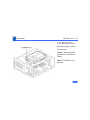
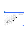
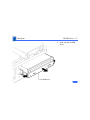
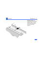
1
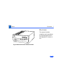
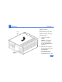
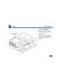
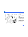
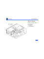
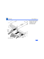
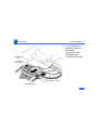
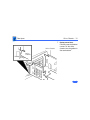
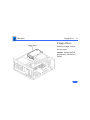
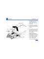
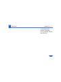
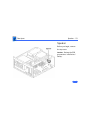
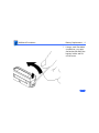
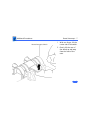
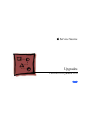
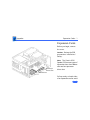
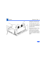
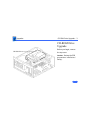
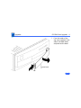
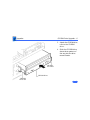
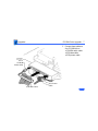
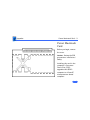
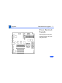
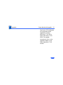
K Service Source
Centris 650/Quadra 650
K Service Source
Basics
Centris 650/Quadra 650
Basics
Overview - 1
Overview
This manual includes
complete repair procedures
for the Macintosh Centris
650/Quadra 650 shown at
left.
Figure: Macintosh Centris 650/Quadra 650
K Service Source
Specifications
Centris 650/Quadra 650
Specifications
Processors - 1
Processors
Centris 650
Quadra 650
Coprocessor
Addressing
Motorola 68040
25 MHz
Built-in memory management unit (MMU)
Motorola 68040
33 MHz
Built-in memory management unit (MMU)
Optional floating-point unit (FPU)
32-bit internal registers
32-bit address bus
32-bit data bus
Specifications
Memory - 2
Memory
RAM
4 or 8 MB RAM, expandable to 132 MB (72-pin SIMM)
ROM
1 MB
PRAM
256 bytes nonvolatile parameter memory
VRAM
512K, expandable to 1 MB
Clock/calendar
CMOS custom chip with long-life lithium battery
Specifications
Disk Storage - 3
Disk Storage
Floppy Drive
1.4 MB Apple SuperDrive
Hard Drive
Internal Apple SCSI hard drive
80 MB to 500 MB
CD-ROM
Optional internal 5.25-in. CD-ROM drive
Specifications
I/O Interfaces - 4
I/O Interfaces
SCSI
Apple Desktop Bus
Serial
NuBus
One SCSI port; DB-25 connector
Supports a maximum of six external devices (internal SCSI
devices include the computer, which is always device 7)
Two Apple Desktop Bus (ADB) ports; mini-Din-4 connectors
Low-speed synchronous serial interface
Two RS-232/RS-422 serial ports; mini DIN-8 connectors
230.4 Kbps maximum
0.92 Mbps maximum, clocked externally
Three NuBus slots
Specifications
I/O Interfaces - 5
Expansion Slot
One inline processor-direct slot
Sound
One stereo-capable output port
One monaural input port
Video
Ethernet
One video port, DB-15 connector
Supports Apple monitors (8-bit)
VGA and SVGA monitors require a special adapter cable
On-board Apple Ethernet port
Specifications
I/O Devices - 6
I/O Devices
Keyboard
Mouse
Microphone
Standard, extended, or adjustable keyboard connected through two
ADB ports
Maximum power draw for all ADB devices: 500 mA
Keyboard draws 25–80 mA
ADB Mouse II; mechanical tracking optical shaft or contact
encoding (low power)
Optional electret, omnidirectional microphone
Microphone output voltage is 4 mV peak to peak at normal value
Mini phone plug connector
Specifications
Sound and Video - 7
Sound and Video
Video Display
Centris 650/Quadra 650 supports these Apple monitors:
• Macintosh 12” Monochrome Display
• Macintosh 12” RGB Display
• AppleColor High-Res RGB 13” Monitor
• Macintosh Color Display
• Macintosh 15” Portrait Display
• Macintosh 16” Color Display
• Apple Two-Page 21” Monochrome Monitor
• Macintosh 21” Color Display
Supports NTSC and PAL
Supports VGA monitors (640 pixels by 480 pixels only) and
SVGA monitors (800 pixels by 600 pixels only) with
appropriate adapter cable
Specifications
Sound
Sound and Video - 8
Custom sound chip supports stereo playback from compact discs
and computer-generated stereo sounds through stereo output port
Monaural sound input port
Specifications
Electrical - 9
Electrical
Line Voltage
100–240 VAC
Frequency
50–60 Hz
112 W maximum, not including display power
Specifications
Physical - 10
Physical
Dimensions
Height: 6.0 in. (152 mm)
Width: 13.0 in. (330 mm)
Depth: 16.5 in. (419 mm)
Weight
25 lb. (11.3 kg)
Weight will vary based on internal devices installed.
Specifications
Environmental - 11
Environmental
Operating
Temperature
Storage
Temperature
50–104°F (10–40°C)
–40F to 116.6°F (–40 to 47°C)
Relative Humidity
10–90% RH (noncondensing)
Altitude
0–10,000 ft. (3,048 m)
K Service Source
Troubleshooting
Centris 650/Quadra 650
Troubleshooting
General/ - 1
General
The Symptom Charts included in this chapter will help you
diagnose specific symptoms related to your product. Because cures
are listed on the charts in the order of most likely solution, try
the first cure first. Verify whether or not the product continues to
exhibit the symptom. If the symptom persists, try the next cure.
(Note: If you have replaced a module, reinstall the original module
before you proceed to the next cure.)
If you are not sure what the problem is, or if the Symptom Charts
do not resolve the problem, refer to the Flowchart for the product
family.
For additional assistance, contact Apple Technical Support.
Troubleshooting
Symptom Charts/Error Chords - 2
Symptom Charts
Error Chords
One-part error
chord sounds during
startupsequence
1
2
3
Disconnect hard drive power cable and hard drive data cable.
Reboot system. If startup sequence is normal, run Macintosh
Hard Disk test and replace hard drive if necessary.
Disconnect floppy drive cable and reboot system. If startup
sequence is normal, replace floppy drive.
Replace logic board. Retain customer’s SIMMs.
Troubleshooting
Symptom Charts/System - 3
System
Does not power on;
screen is black, fan is
not running and LED
is not lit
1
2
3
4
5
Check cables.
Plug monitor directly into wall socket, and verify that
monitor has power.
Replace power cord.
Replace power supply.
Replace logic board.
Clicking, Chirping or
thumping
1
2
Replace power supply.
Replace logic board. Retain customer’s SIMMs.
Troubleshooting
Symptom Charts/System (Continued) - 4
System (Continued)
System shuts down
intermittently
1
4
5
Check that air vents are clear. Thermal protection circuitry
may shut down system. After 30 to 40 minutes, system
should be OK.
Replace power cord.
Check batteries. Refer to “Battery Verification” in
Additional Procedures.
Replace power supply.
Replace logic board. Retain customer’s SIMMs.
1
2
3
4
5
6
Verify that system software is correct version.
Disconnect external SCSI devices.
Verify that software is known-good.
Replace SIMMs. (Refer to Hardware/Memory.)
Replace power supply.
Replace logic board. Retain customer’s SIMMs
2
3
System
intermittently
crashes or locks up.
Troubleshooting
Symptom Charts/ System (Continued) - 5
System (Continued)
Does not start up with
out a monitor attached
Verify that the Chooser and Control Panels are set correctly.
Troubleshooting
Symptom Charts/Video - 6
Video
Screen is dark, audio
and at least one drive
operate, fan is
running, and LED is
lit
Screen is dark, audio
and drive do not
operate, fan is
running, and LED is
lit
1
2
5
6
7
Adjust brightness on monitor.
Clear parameter RAM. Hold down <Command> <Option>
<P><R> during startup but before Welcome to Mac appears.
Check cables.
Replace monitor. Refer to appropriate monitor manual to
troubleshoot defective monitor.
Replace video card.
Replace VRAM SIMMs.
Replace logic board. Retain customer’s SIMMs.
1
2
3
4
5
6
Remove peripherals.
Remove NuBus cards.
Replace DRAM SIMMs.
Replace VRAM SIMMs.
Replace power supply.
Replace logic board.
3
4
Troubleshooting
Symptom Charts/Video (Continued) - 7
Video (Continued)
Partial or whole
screen is bright and
audio is present, but
no video information
is visible
Screen is completely
dark, fan is not
running, and LED is
not lit
1
2
4
5
6
Check cables
Clear parameter RAM. Hold down <Command> <Option>
<P><R> during startup but before Welcome to Macintosh
appears.
Replace monitor. Refer to appropriate monitor manual to
troubleshoot defective monitor.
Replace video cable.
Replace VRAM SIMMs.
Replace logic board. Retain customer’s SIMMs.
1
2
3
4
5
Verify that external power cables are properly connected.
Remove peripherals.
Remove NuBus cards.
Replace power supply.
Replace logic board. Retain customer’s SIMMs.
3
Troubleshooting
Symptom Charts/Floppy Drive - 8
Floppy Drive
Audio and video are
present, but internal
floppy drive does not
operate
1
2
3
Replace internal floppy drive cable.
Replace internal floppy drive.
Replace logic board. Retain customer’s SIMMs.
Floppy disk ejects,
and display shows Mac
icon with blinking
“X”
1
2
3
4
Replace floppy disk.
Replace floppy drive cable.
Replace internal floppy drive.
Replace logic board. Retain customer’s SIMMs.
Floppy disk does not
eject
1
Switch off system and hold mouse button down while
switching on.
Eject disk manually.
Replace floppy drive cable.
Replace floppy drive.
2
3
4
Troubleshooting
Symptom Charts/Floppy Drive (Continued) - 9
Floppy Drive (Continued)
Floppy drive
attempts to eject disk
but doesn’t
1
2
3
Push floppy disk completely in.
Eject floppy disk manually.
Replace floppy drive.
Troubleshooting
Symptom Charts/Hard Drive - 10
Hard Drive
Internal hard drive
runs continuously
1
2
3
Replace SCSI data cable.
Replace internal hard drive.
Replace logic board. Retain customer’s SIMMs.
Internal hard drive
does not operate
1
2
3
4
Replace SCSI data cable.
Replace SCSI power cable.
Replace hard drive.
Replace logic board. Retain customer’s SIMMs.
Troubleshooting
Symptom Charts/CD-ROM Drive - 11
CD-ROM Drive
CD-ROM drive does
not accept a compact
disc
1
2
Exchange disk (if disk is dirty or
damaged).
Replace CD-ROM drive mechanism.
Macintosh does not
display CD-ROM
drive icon
1
2
3
4
5
Verify that CD-ROM extension is in System Folder.
Verify the disc is in the drive correctly.
Replace CD-ROM drive mechanism.
Replace power supply.
Replace SCSI data cable.
Troubleshooting
Symptom Charts/Peripheral - 12
Peripheral
Works with internal
or external SCSI
device, but does not
work with both
1
2
3
4
5
Verify that SCSI select switch on any external device is set
differently from any internal SCSI device.
Verify that the hard drive is terminated and the CD-ROM
drive is not terminated.
Replace the terminator on external SCSI device.
Replace SCSI cable.
Replace the SCSI select cable on external SCSI device.
Troubleshooting
Symptom Charts/Peripheral (Continued) - 13
Peripheral (Continued)
Cursor moves, but
clicking the mouse
button has no effect
1
2
Replace mouse.
Replace logic board. Retain customer’s SIMMs.
Double-click does not
open application,
disk, or server
1
2
Remove duplicate system files from hard drive.
Clear parameter RAM. Hold down <Command> <Option>
<P><R> during startup but before Welcome to Macintosh
appears.
If mouse was connected to keyboard, connect mouse to
computer ADB port instead. If mouse works, replace
keyboard.
If mouse does not work in any ADB port on computer, replace
mouse.
Replace logic board. Retain customer’s SIMMs.
3
4
5
Troubleshooting
Symptom Charts/Peripheral (Continued) - 14
Peripheral (Continued)
No response to any
key on the keyboard
1
2
3
4
Verify that keyboard is connected to ADB port.
Replace keyboard cable.
Replace keyboard.
Replace logic board. Retain customer’s SIMMs.
Cursor does not move
1
2
3
Reboot computer.
Verify that mouse is connected properly.
Clear parameter RAM. Hold down <Command> <Option>
<P><R> during startup but before Welcome to Macintosh
appears.
If mouse was connected to keyboard, connect mouse to
computer ADB port instead. If mouse works, replace
keyboard.
If mouse does not work in any ADB port on computer, replace
mouse.
Replace logic board. Retain customer’s SIMMs.
4
5
6
K Service Source
Take Apart
Centris 650/Quadra 650
Take Apart
Top Cover - 1
Top Cover
Top
Cover
No preliminary steps are
required before you begin
this procedure.
1
2
Captive
Screw
Loosen the captive
screw.
Caution: Excessive
force on the captive
screw will damage the
top cover.
Note: Do not attempt to
tilt the top cover when
you remove it.
Slide the top cover
toward the front 1 inch.
Take Apart
Top Cover - 2
Lift the top cover
straight up.
Replacement Note: Do
not jar the reset/
interrupt switch and
light pipe out of
alignment when you
replace the top cover.
Take Apart
Power Supply - 3
Power Supply
Before you begin remove
the top cover.
Caution: Review the ESD
precautions in Bulletins/
Safety.
Take Apart
Power Supply - 4
1
CD-ROM Drive
If a CD-ROM drive is
installed, squeeze its
side tabs and pull the
drive out an inch or two
to more easily reach the
power supply.
Take Apart
Power Supply - 5
2
Power Supply
Screw
Rear Bezel
Power Supply
3
4
Remove the power
supply screw from the
rear bezel.
Pry the latch away from
the base of the power
supply.
Grasp the power supply
and firmly lift it out of
the drive mount chassis.
Note: The firm lifting
motion disconnects the
power supply connector
from the logic board.
Latch
Take Apart
Drive Chassis - 6
Drive Chassis
Before you begin, remove
the following:
• Top cover
• P ower supply
Take Apart
Drive Chassis - 7
1
Floppy
Drive
Cable
SCSI Data Cable
SCSI Power
Cable
Disconnect these cables:
• Floppy drive cable
• SCSI power cable
• SCSI data cable
Take Apart
Drive Chassis - 8
2
CD-ROM
Drive
CD-ROM
Audio Cable
SCSI Data Cable
SCSI Power Cable
If a CD-ROM drive is
installed, disconnect
these cables:
• SCSI power cable
• SCSI data cable
• CD-ROM audio cable
Take Apart
Drive Chassis - 9
3
Drive Chassis
Remove the two drive
chassis screws.
Take Apart
Drive Chassis - 10
4
Lift the front of the
drive chassis until the
chassis is perpendicular
to the bottom case.
Note: The chassis
swivels where the
chassis tabs meet the
bottom cover.
Take Apart
Drive Chassis - 11
5
Chassis
(Perpendicular
for Removal)
Chassis
(Installed)
6
Pull the chassis forward
and gently guide the
chassis tabs from the
slots in the bottom case.
Remove the chassis.
Take Apart
Drive Chassis - 12
7
Drive Chassis
Guides
Drive
Chassis
Replacement Note:
Carefully seat the bottom
corners of the drive
chassis into the guides in
the case bottom.
Take Apart
Floppy Drive - 13
Floppy Drive
Before you begin, remove
the top cover.
Caution: Review the ESD
precautions in Bulletins/
Safety.
Take Apart
Floppy Drive - 14
Floppy Drive
1
2
3
Screw
Disconnect the floppy
drive cable from the
floppy drive.
Remove the floppy drive
mounting screw.
Pry up the mounting tab
and slide out the floppy
drive.
Replacement Note: You may
encounter either an autoinject or manual-inject 1.4
MB floppy drive. Replace
floppy drives like for like.
Tab
Floppy
Drive
Cable
Take Apart
Hard Drive - 15
Hard Drive
Before you begin, remove
the top cover.
Caution: Review the ESD
precautions in Bulletins/
Safety.
Take Apart
Hard Drive - 16
1
Hard Drive
2
3
Screw
SCSI Data
Cable
SCSI Power Cable
Disconnect the SCSI data
cable and the SCSI
power cable from the
hard drive.
Remove the hard drive
mounting screw from the
carrier.
Lift the back of the hard
drive and slide the hard
drive carrier out of the
drive chassis.
Replacement Note: For
information on removing
the hard drive from the
carrier and returning
drives, cables, and
carriers to Apple, refer
Take Apart
Hard Drive - 17
to the Hard Drives
manual (Hardware/
Service Manual/Drives/
Hard Drives).
Take Apart
CD-ROM Drive - 18
CD-ROM Drive
Before you begin, remove
the top cover.
Caution: Review the ESD
precautions in Bulletins/
Safety.
Note: A CD-ROM Drive is
optional.
Take Apart
CD-ROM Drive - 19
1
CD-ROM Drive
Squeeze the side tabs and
pull the drive out a few
inches to more easily
perform the next step.
Take Apart
CD-ROM Drive - 20
2
CD-ROM
Drive
CD-ROM
Audio Cable
SCSI Data Cable
SCSI Power Cable
Disconnect these cables
from the CD-ROM drive:
• Audio cable
• SCSI power cable
• SCSI data cable
Take Apart
CD-ROM Drive - 21
3
CD-ROM Drive
Slide out the CD-ROM
drive.
Take Apart
CD-ROM Drive - 22
Key
Replacement Note: The
connectors on the SCSI data
cable are keyed. You may
need to twist the cable to
insert the connector
properly.
Take Apart
Speaker - 23
Speaker
Before you begin, remove
the top cover.
Caution: Review the ESD
precautions in Bulletins/
Safety.
Take Apart
Speaker - 24
1
2
Speaker
Speaker
Cable
Logic Board
Disconnect the speaker
cable from the logic
board.
Remove the speaker
mounting screws and
pull out the speaker.
Note: There is more than
one version of speaker for
the computer. Speakers
install with four or two
screws, depending on the
version.
Take Apart
Logic Board - 25
Logic Board
Before you begin, remove
the following:
• Top cover
• P ower supply
• Drive chassis
• Reset/Interrupt switch
• Speaker
Logic
Board
Take Apart
Logic Board - 26
1
Screw
2
Remove the screw in the
center of the logic board.
Slide the logic board
toward the front about
1/2 inch and lift the
board out of the case.
Take Apart
Logic Board - 27
Replacement Note: Remove
the customer’s SIMMs from
the defective logic board and
install them on the
replacement logic board.
(See Hardware/Memory.)
Replacement Note: The logic
boards of the various
models of the computer are
similar. Be sure to install
the correct board.
Logic Board
Logic Board
Replacement Note: Position
the center rear edge of the
logic board in the plastic
bracket and slide the board
straight back.
K Service Source
Additional Procedures
Centris 650/Quadra 650
Additional Procedures
Battery Verification - 1
Battery
Battery
Verification
Before you begin, remove
the top cover.
Warning: If handled or
discarded improperly, the
lithium battery could
explode. Review batteryhandling and disposal
instructions in Bulletins/
Safety.
Caution: Review the ESD
precautions in Bulletins/
Safety.
Additional Procedures
Battery Verification - 2
1
2
Negative
Probe
Positive
Probe
3
Set the voltmeter to the
10 volts DC scale.
Hold the positive probe
of the voltmeter to the
positive end of the
battery (marked “+”
on the logic board) and
the negative probe to the
negative end of the
battery.
If the battery voltage is
below 3.2 volts, replace
the battery. Refer to
“Battery Replacement”
in this chapter.
Additional Procedures
Battery Replacement - 3
Battery
Battery
Replacement
Before you begin, remove
the top cover.
Warning: If handled or
discarded improperly, the
lithium battery could
explode. Review battery
handling and disposal
instructions in Bulletins/
Safety.
Caution: Review the ESD
precautions in Bulletins/
Safety.
Additional Procedures
Battery Replacement - 4
1
Using a small flat-blade
screwdriver, pry open
the latch at the end of the
battery holder and lift
off the cover.
Additional Procedures
Battery Replacement - 5
2
3
Grasp the battery and
remove it from the
holder.
Return the battery to
Apple for proper
disposal. For battery
packaging and labeling
instructions, refer to
the safety information in
Bulletins/Safety.
Additional Procedures
Reset/Interrupt - 6
Reset/Interrupt
Before you begin, remove
the cover.
Caution: Review the ESD
precautions in Bulletins/
Safety.
Reset/Interrupt
Switch
Additional Procedures
Reset/Interrupt Switch
Reset/Interrupt - 7
1
2
With one finger, lift the
center tab of the switch.
Gently lift the rear of
the switch up and away
from the front of the
case.
K Service Source
Upgrades
Centris 650/Quadra 650
Upgrades
Expansion Cards - 1
Expansion Cards
Before you begin, remove
the cover.
Caution: Review the ESD
precautions in Bulletins/
Safety.
Processor
Direct Slot
Note: The Centris 650/
Quadra 650 has two types of
expansion slots: three Nubus
slots and one processor
direct slot.
NuBus Slots
Pull up evenly on both sides
of an expansion card to avoid
Upgrades
Expansion Cards - 2
bending the connector pins.
Carefully grasp each end of
the card and pull straight up
to remove the card from the
expansion slot.
Replacement Caution: When
replacing the card, do not
force it into the expansion
slot. If the card does not seat
properly, remove it and try
again.
Upgrades
CD-ROM Drive Upgrade - 3
CD-ROM Drive
Upgrade
CD-ROM Drive
Before you begin, remove
the top cover.
Caution: Review the ESD
precautions in Bulletins/
Safety.
Upgrades
CD-ROM Drive Upgrade - 4
1
Blank Bezel
Tab
From the inside of the
top cover, squeeze in the
tabs of the blank bezel
and push out the bezel.
Upgrades
CD-ROM Drive Upgrade - 5
2
Slotted Bezel
Push in the slotted bezel.
Upgrades
CD-ROM Drive Upgrade - 6
3
4
CD-ROM
Drive Rail
CD-ROM
Drive Rail
CD-ROM Drive
Attach the CD-ROM drive
rails to the CD-ROM
drive.
Slide the CD-ROM drive
about three quarters of
the way into the drive
mount chassis.
Upgrades
CD-ROM Drive Upgrade - 7
5
Drive
CD-ROM
Audio Cable
SCSI Data Cable
SCSI Power
Cable
Connect these cables to
the CD-ROM drive:
• CD-ROM audio cable
• SCSI data cable
• SCSI power cable
Upgrades
CD-ROM Drive Upgrade - 8
6
CD-ROM Drive
Push the CD-ROM drive
completely into the CDROM slot until you hear
a click.
Upgrades
Power Macintosh Card - 9
Power Macintosh
Card
Before you begin, remove
the cover.
Caution: Review the ESD
precautions in Bulletins/
Safety.
Installing this card in the
computer’s ProcessorDirect Slot (PDS),
upgrades this 68040
computer to a PowerPC
microprocessor–based
computer.
Upgrades
Power Macintosh Card - 10
For more information,
including installation
instructions, refer to the
Basics chapter in the Power
Macintosh Card manual.
Upgrades
Power Macintosh Upgrade - 11
Power Macintosh
Upgrade
No preliminary steps are
required before you begin
this procedure.
Upgrades
Power Macintosh Upgrade - 12
The Centris 650 and Quadra
650 computers can be
upgraded to a Power
Macintosh 7100/66 or
Power Macintosh 7100/
66AV. For upgrade
instructions, refer to the
Upgrades chapter in the
Power Macintosh 7100
manual.
K Service Source
Exploded View
Centris 650/Quadra 650
Exploded View
1
Exploded View
Blank Bezel
922-1373
CD-ROM with
Caddy Bezel
922-0404
CD-ROM
Caddyless Bezel
922-0800
Front Panel
922-0542
Top Cover
922-0405
Floppy Drive Cable
922-0112
Floppy Drive Carrier
922-0763
Power Supply Strap
922-0906
Power Supply
661-0758
Internal Chassis
922-0058
CD-ROM Audio Cable
922-0842
Light Pipe
815-6272
EMI Gasket
922-0887
Floppy Drive
661-0121
661-0474
* Hard Drive
Hard Drive Carrier
922-0066
Hard Drive
CD-ROM
SCSI Cable
922-0053
Power Cable
922-0051
CD-ROM Drive
922-0826
CD Carrier Rails
922-0067
* Logic Board
Speaker
922-0055
Bottom Case
922-0406
NuBus Access Cover
810-6035
This is a generic representation of a product family. Configurations may vary.
For number of part with asterisk, see parts list.