1
ELECTRIC DUCT
HEATERS
INSTALLATION, OPERATION
AND MAINTENANCE MANUAL
Stock ID: IOM-EDH
Reprinted June, 2001
©2001 Environmental Technologies, Inc.
Largo, FL • Part No. PX-00-0141
ELECTRIC DUCT HEATER • I.O.M.
TABLE OF CONTENTS
DESCRIPTION
PAGE
Pre Start-Up ........................................................................................................................................3
Receiving and Inspection ....................................................................................................................3
Unit Placement ...................................................................................................................................3
Clearance ............................................................................................................................................3
Electric Heater Warning Labels ...........................................................................................................4
Minimum Air Velocities
Open Coil Construction.................................................................................................................5
Finned Tubular Construction .........................................................................................................5
Heater Installation Instructions
Side Slip-In ....................................................................................................................................6
Insulated .......................................................................................................................................6
Flanged .........................................................................................................................................7
Round Duct ...................................................................................................................................7
Remote Control Panel ...................................................................................................................7
Minimum Wire Gauge ........................................................................................................................8
Field Wiring ........................................................................................................................................8
Preventative Maintenance...................................................................................................................8
Ampere Reading per kW.....................................................................................................................9
Airflow Switch Probe Reversal ............................................................................................................9
Troubleshooting Guide .......................................................................................................................9
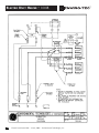
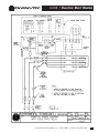
Sample Submittal Wiring Diagrams ...................................................................................................10
Troubleshooting Guide, Proportional Heat Control (SSR)...................................................................12
Troubleshooting Guide, Vernier Heat Control ....................................................................................14
Replacement Parts .............................................................................................................................14
Important Safety Precautions......................................................................................................15
2
Electric Duct Heater IOM • ©June, 2001 • Environmental Technologies, Inc.
I.O.M. • ELECTRIC DUCT HEATER
PRE START-UP
WARNING:
Improper installation, adjustments, alterations, service or maintenance can cause injury and
property damage, as well as possible voiding of factory warranty. For assistance or additional
information, consult a qualified contractor and your local ENVIRO-TEC® representative.
RECEIVING AND INSPECTING
• Thoroughly examine the exterior and interior of all units for transportation damage. If damage is found,
immediately file a claim with the carrier. Note the damage on the bill of lading when signing for the shipment.
• Check the bill of lading to verify that all items shown (including loose items) have been received. Notify the
ENVIRO-TEC® representative of any shortages or items shipped in error.
• Do not handle the unit's heating elements, as permanent damage may occur.
UNIT PLACEMENT
CAUTION: Never energize a heater without proper airflow.
• Install ductwork to comply with ASHRAE Fundamentals Handbook, SMACNA, NFPA 90A and local code.
• ENVIRO-TEC® duct heaters are manufactured under ETL File #549556, or ETLC File #548276, and must be installed
in compliance with all National and Local Codes. Improper installation of these units can result in the removal of
the Listing Label and/or voiding of the Warranty. Airflow and airflow patterns are important to the operation and
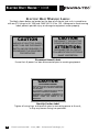
life of the heater (see airflow graphs on page 5). Proper airflow will also prevent nuisance tripping of
the thermal safety devices.
• Open coil duct heaters are certified for horizontal airflow in either direction, or for vertical up airflow. Some
heaters may contain position sensitive devices (mercury contactors or Solid State Relays) and can only be mounted in their specific designed configuration. These heaters will be marked with specified mounting configuration
labels. Do not install a slip-in or flanged heater intended for side mount on the top or bottom of horizontal duct.
Do not install a heater marked for horizontal airflow in vertical duct or a vertical heater in horizontal duct.
• When an airflow switch is used as a fan interlock, the heater will contain an air pick-up probe. The pick-up probe
contains a directional arrow and may be rotated on horizontal units only (see figure 6 on page 9).
• Install units in a section of duct with uniform air velocity across the full face area of the duct. For best
performance, heaters should be mounted a minimum of 4 feet downstream of a heat pump, transition, air
conditioner or other obstructions in the duct work. Per NEC Article 424-59, turning vanes, pressure plates or other
devices may be used to ensure even air distribution if mounted less than 4 feet. Duct heaters for internally
insulated ducts will be designed to accommodate insulation thickness.
CLEARANCE
• All electric heat units are ETL listed for zero clearance to combustibles. Therefore, the element frame height will
be 1" less on uninsulated duct and the width will be 1/2" less.
• All electrical panels must have 36" working space in front of panel to meet NATIONAL ELECTRICAL CODE;
however, local inspectors may wave this requirement if the hinged cover has a 90° free swing.
Environmental Technologies, Inc. •©June, 2001 • Electric Duct Heater IOM
3
ELECTRIC DUCT HEATER • I.O.M.
ELECTRIC HEAT WARNING LABELS
The labels shown below are located on the door of all electric heat units in compliance
with our ETL listings to UL 1996 and CAN/CSA C22.2 No. 155. Adherence to these warning
labels prevents possible injury or damage to equipment and/or property.
CAUTION
CAUTION
HAZARD OF ELECTRIC SHOCK.
MORE THAN ONE DISCONNECT
SWITCH MAY BE REQUIRED TO
DE-ENERGIZE THE EQUIPMENT
FOR SERVICING.
DISCONNECT THE ELECTRIC
POWER BEFORE SERVICING.
ATTENTION:
DECONNECTER DU CIRCUIT
D’ALIMENTATION ELECTRIQUE
AVANT L’ENTRETIEN.
Disconnect Hazard Labels
Ensure that all power has been disconnected prior to servicing equipment.
CAUTION
ELECTRICAL HAZARD
AFTER INSTALLATION AND BEFORE ENERGIZING
THIS UNIT, CHECK ALL ELECTRICAL CONNECTIONS
FOR TIGHTNESS.
ALL ELECTRICAL CONNECTIONS SHOULD THEN BE
PERIODICALLY CHECKED FOR TIGHTNESS.
ALTERNATION OF INTERNAL COMPONENTS OR
WIRING WILL FURTHER RESULT IN REMOVAL OF THE
PRODUCT LISTING AND VOIDING OF ALL
WARRANTIES.
Start-Up Caution Label
Tighten all wiring lugs and terminals prior to connecting power to the unit,
as they may loosen during transportation.
4
Electric Duct Heater IOM • ©June, 2001 • Environmental Technologies, Inc.
I.O.M. • ELECTRIC DUCT HEATER
MINIMUM AIR VELOCITIES
1600
60
VELOCITY (FPM)
1200
1000
40
800
25
10
600
0
ENTERING AIR (Deg. F)
80
1400
400
200
0
0
2
4
6
8
10
12
14
16
18
20
22
24
KW/SQ FT.
OPEN COIL CONSTRUCTION
M/MIN. FPM
304.8 1000
274.2 900
243.6 800
VELOCITY
213.0 700
HORIZONTAL AIRFLOW
182.4 600
152.4 500
121.8 400
VERTICAL AIRFLOW
91.2 300
INLET AIR TEMPERATURE
77°F, 25°C
60.6 200
30.0 100
0
1
2
3
4
5
6
7
8
9
10
11
12
13
14
15
KW/SQ FT.
15.5 Maximum Kw/Sq. Ft.
FINNED TUBULAR CONSTRUCTION
Environmental Technologies, Inc. •©June, 2001 • Electric Duct Heater IOM
5
ELECTRIC DUCT HEATER • I.O.M.
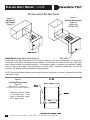
INSTALLATION INSTRUCTIONS
Figure 1
Horizontal
Duct Heater
(Type SS)
Figure 2
Vertical Duct Heater
(Type VS)
Vertical Up
Airflow Only
Model EDHSS (Side Slip-In, Vertical Slip-In)
Installation of the slip-in heater consists of cutting an opening in the duct approximately 1/4" larger than
the height and width of the heater element section. Insert heater and fasten to the duct using sheet
metal screws through the control enclosure. Use extreme caution in protecting the electrical components, as metal chips lodged in the components can cause failure. Remove any metal chips that may be
located in the electrical enclosure before connecting power.
NOTE: To prevent element section from moving inside duct, angle clips, brackets, or blank offs should be
attached to frame.
Figure 3
Insulated Duct Heater
(Type SS)
NOTE: Heaters are designed to
accommodate the insulation thickness.
Mounting electric heater
in insulated duct is the
same as described above
for SS type heaters.
6
Electric Duct Heater IOM • ©June, 2001 • Environmental Technologies, Inc.
I.O.M. • ELECTRIC DUCT HEATER
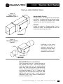
INSTALLATION INSTRUCTIONS
Figure 4
Flange Heater
Installation (Type SF)
Model EDHSF (Flanged)
Flanged heaters are designed with the flanges
turned out. Installation of the side flanged heater
consists of inserting the flanged duct heater
section into the duct and bolting in place.
Raintight
Heaters are sealed in a flanged section. Unit is
mounted as above. A weatherproof seal must be
made when mounting these units.
Figure 5
Round Duct Heater
(Type RD)
Installation of the round
duct heater consists of
attaching round duct to
the inlet and outlet collars
and bolting in place. Seal
connection and duct joint.
Model RCMP (Remote Control Panel)
Install the control panel in a suitable location for
the specified panel type. The wiring diagrams
inside the heater door and the remote control
panel door show point-to-point interconnecting
wiring. Wiring must be letter to letter ("a" to "a")
or number to number ("1" to "1"). Labels on each
door specify the (heater/panel) configuration. DO
NOT deviate from this label. Panels should be
mounted in sight of unit, unless an additional disconnect is located at unit.
Environmental Technologies, Inc. •©June, 2001 • Electric Duct Heater IOM
7
ELECTRIC DUCT HEATER • I.O.M.
MINIMUM WIRE GAUGE
(from Table 310-16 NEC 1996 wire rated 75°C)
MINIMUM WIRE GAUGE
AMPERES
14 AWG
175
12 AWG
200
10 AWG
230
8 AWG
255
6 AWG
285
4 AWG
310
3 AWG
335
2 AWG
380
1 AWG
420
1/0 AWG
AMPERES
20
25
35
50
65
85
100
115
130
150
POWER WIRING
L1
L2
L3
N
Ground
Black
Red
Blue
White
Green
CONTROL WIRING
Stages
Step 1
Red
Step 2
Purple
Step 3
Orange
Step 4
Brown
Fan Output
Black
MINIMUM WIRE GAUGE
2/0 AWG
3/0 AWG
4/0 AWG
250 kcmil
300 kcmil
350 kcmil
400 kcmil
500 kcmil
600 kcmil
TRANSFORMER WIRING
Primary Voltage (same as Power Wiring)
SECONDARY
24 Volt
277 & 120 Volt
Negative
Yellow
Negative
Red
Positive
Blue
Positive
Black
NOTE: Units with wire gauges
8 and greater will be color
coded with tape.
FIELD WIRING
NOTE: Prior to installing any wiring, check the unit name plate for main power voltage, control voltage and maximum
overcurrent protection. Operating a heater at other than the specified voltage and phase can result in fire or electrical hazard.
All field wiring must comply with NATIONAL ELECTRIC CODE and local code requirements. A point-to-point wiring diagram is
located on the inside of the control panel door, which details wiring and field wire gauge.
• Use copper conductors only with a minimum of 75°C insulation.
• Tighten all wiring lugs and terminals prior to connecting power to the unit, as they may loosen during transportation.
• Connect the power lines to the power distribution terminals inside the control enclosure and tighten to 35 inch-pounds
(.4kg meters). If a factory wired disconnect switch is installed, connect the power lines to the line side of the switch. The line
block or disconnect is rated at 125% of nominal heater amperes based on 75°C wire.
• Mount and wire any field installed items as indicated on the factory supplied wiring diagram. When mounting field installed
components, do not jumper out or rewire any factory wiring without written approval from Environmental Technologies, Inc.
only. Violation will void warranty and listing.
• Energize unit and check all controls for proper operation. Do not operate unit without proper airflow.
ELECTRIC HEATER PREVENTATIVE MAINTENANCE CHECKS & SERVICE SCHEDULE
CAUTION!
DISCONNECT ALL POWER SOURCES BEFORE ATTEMPTING
TO
SERVICE
OR
CLEAN HEATER
Before, and at Midpoint of the Heating Season:
• Check all electrical connections for tightness and broken terminations.
• Check all wiring for deterioration or over heating.
• Check unit for dirt or dust, and wipe clean (except elements).
• Check the element section for obstructions and debris.
• Check all components for wear and physical damage.
• Check all safety devices for proper operation.
• Check temperature controls for proper operation.
CAUTION:
In the event of thermal protection failure, it is recommended that a qualified service person
investigate the cause of failure prior to returning the heater to normal service.
8
Electric Duct Heater IOM • ©June, 2001 • Environmental Technologies, Inc.
I.O.M. • ELECTRIC DUCT HEATER
Figure 6
Airflow Switch Probe Reversal
AMPERE READING PER KW
VOLTAGE/PHASE
AMPERES/KW
120 / 1
8.33
208 / 1
4.80
240 / 1
4.16
277 / 1
3.61
480 / 1
2.08
208 / 3
2.77
240 / 3
2.40
480 / 3
1.202
Airflow switch probe is installed in accordance with the specification. If application dictates opposite airflow, rotate the probe
180°. Directional arrow is stamped on airflow sensing probe.
DOES NOT APPLY TO VERTICAL UNITS.
TROUBLESHOOTING
• Check installation instructions and wiring diagrams to ensure heater is wired and installed properly.
COMMON SYMPTOMS
Heater Does Not Operate
Low or High Temperature
Rise
Short Cycling
Heater w/SSR
Does Not Operate
POSSIBLE CAUSE
REMEDY
No Power
No Control Voltage
• Check disconnect
• Check control signal (i.e. 24volt)
• Check transformer and transformer
fusing (if applicable), replace if necessary
Blown Fuse
• Replace fuse
Open Limit (primary or secondary)
• Replace limits or reset as applicable
• Check for continuity across limit to
determine if open, replace as necessary
Airflow Incorrect Direction
• Check sensing tube, rotate if needed
(see Figure 6 above)
Low Airflow Static Pressure
• Increase airflow
Damaged Elements
• Check for open or damaged
elements and replace as necessary
Incompatible Thermostat or Controller • Check wiring
• Check for compatibility
Problems with Additional Stages
• Check location of thermostat; may be
installed in a ”too hot” or ”too cold”
location
• Check contactors for open coil
• Check for damaged elements
Incorrect CFM
• Check for blocked duct or location
of heater
Improper Airflow
• Check for even airflow across
the face of element section
• Check for blocked duct
• Check for dirty filters
Low CFM
• See remedies for “Improper Airflow“
• Check air velocity
Incorrect Signal Applied
• Verify signal input
• See page 8 (Troubleshooting Guide)
Interface Board Fuse Blown
• Replace fuse
(See page 8 [Troubleshooting Guide]
for correct size and type)
Environmental Technologies, Inc. •©June, 2001 • Electric Duct Heater IOM
9
ELECTRIC DUCT HEATER • I.O.M.
10
Electric Duct Heater IOM • ©June, 2001 • Environmental Technologies, Inc.
I.O.M. • ELECTRIC DUCT HEATER
Environmental Technologies, Inc. •©June, 2001 • Electric Duct Heater IOM
11
ELECTRIC DUCT HEATER • I.O.M.
PROPORTIONAL HEAT CONTROL (SSR) TROUBLESHOOTING GUIDE
CAUTION:
Lethal voltages are present in the heater control enclosure. Use extreme caution
when taking measurements in these units. Always disconnect power before
removing or re-applying any connections.
1. Before applying power, verify wiring matches diagram in cover of heater control enclosure, and that
correct line voltage has been wired to heater line block.
2. Verify 24 VAC +15% or -10% between P1 and P2 of interface circuit board (ETPHCI, ETPHCT, etc.,
depending on input).
3. If the heat control is used with an ENVIRO-TEC® duct or wall stat, verify +18 VDC + or -0.5 VDC
between the terminals labeled +18 and COM on the interface circuit board, and terminals 1 and 2 of
the thermostat. If no voltage is present, check the fuse on the interface circuit board and, if good,
replace the interface circuit board.
4. The table below lists responses to input signal by interface model as explained in step 5. If the voltages from an ENVIRO-TEC® thermostat listed in the table cannot be obtained, proceed to step 10. If
any of the other inputs cannot be obtained, refer to the literature on the device which is supposed to
provide the input. Otherwise, proceed to step 5.
INTERFACE
MODEL
ETPHCI
ETPHCT
ETPHCR
ETPHCV1
ETPHCV2
“PULSE”
INPUT
12.0 mA
9.1 VDC
68 Ω
7.5 VDC
6.0 VDC
FULL OFF
INPUT
4.0 mA
8.4 VDC
0Ω
6.0 VDC
2.0 VDC
FULL ON
INPUT
20.0 mA
9.9 VDC
135 Ω
9.0 VDC
10.0 VDC
5. Apply Full Off Input per table above. If the unit is three phase, verify that the LED on the SSR (solid
state relay) is off. If the unit is single phase, measure voltage between P4 and P6 and verify 0.3 VDC
+ or - 0.3 VDC. Replace the interface circuit board if the voltage is higher than specified, or the LED
is on.
6. Apply Full On Input per table above. If the unit is three phase, verify that the LED on the SSR (solid
state relay) is on. If the unit is single phase, measure voltage between P4 and P6 and verify between
3 and 5 VDC.
7. Apply “Pulse” Input per table above. If the unit is three phase, verify that the LED on the SSR (solid
state relay) is flashing at an interval of about one second. If the unit is single phase, the voltage
between P4 and P6 of the master circuit board should vary between the Full Off and Full On voltages
in steps 5 and 6 in intervals of about one second. NOTE: Some voltmeters will not respond this quickly, so the value of the voltages may not appear to be correct; however, if the voltage appears to be
changing at regular intervals, it may be assumed that this function is operating properly. This completes the low voltage portion of the unit test.
12
Electric Duct Heater IOM • ©June, 2001 • Environmental Technologies, Inc.
I.O.M. • ELECTRIC DUCT HEATER
8. If the heater always remains energized when power is applied, remove the wire from P4 of the
interface circuit board. If the heat remains on, there is a wiring error or the SSR is defective.
CAUTION: Remove Power From the Unit Before Proceeding With the Next Step.
9. If the heater is always de-energized when power is applied, remove the line and load connections to
the proportional heat control and temporarily tie them together. If the system is a three phase
arrangement, do the phases one at a time. (NOTE: Always remove power from the unit before
moving to the next phase). Make sure there is no danger of the temporary connection shorting to
another component or the chassis. Briefly reapply power. If the section of heat under test now
energizes, the SSR is defective. If heater still will not energize, one of the heater safety devices
(limits, safety contactor or airflow switch) or elements is defective.
THERMOSTAT
10. Make sure the temperature being sensed by the thermostat is within its control range:
MODEL
ETSTAT4H
ETSTAT4H1
ETSTAT4H2
ETSTAT4H3
ETSTAT4H4
RANGE
55° - 85° F
45° - 75° F
55° - 85° F
90° - 120° F
105° - 135° F
11. Set the thermostat setpoint to the temperature of the air being sensed. Read the voltage between
terminals 3 (ETSTAT4H) or terminal 5 (all other models) and terminal 2, and verify voltage is between
7 and 9 VDC. If not, replace thermostat (and duct sensor, if applicable).
12. Turn thermostat setpoint up approximately 4°F and verify voltage in step 11 increases by about two
volts. If not, replace thermostat (and duct sensor, if applicable).
Environmental Technologies, Inc. •©June, 2001 • Electric Duct Heater IOM
13
ELECTRIC DUCT HEATER • I.O.M.
VERNIER HEAT CONTROL TROUBLESHOOTING GUIDE
CAUTION: Lethal voltages are present in the heater control enclosure. Use extreme caution when
taking measurements in these units. Always remove power before removing or re-applying any
connections.
1. Before applying power, verify wiring matches diagram in cover of heater control enclosure, and that
correct line voltage has been wired to heater line block. NOTE: Polarity of the 24 VAC signal is
important. If incorrect, controller will not work, and, in some cases, may be damaged.
2. Verify 24 VAC +15% or 10% between terminals 15 and 16 of the vernier controller (ETGC8VP).
3. Verify +5V or 0.25V between the +5Vand COM test loops on controller.
approximately in the center of the board. If zero, check fuse.
These are located
4. LED should be blinking in two second intervals (one second on, one second off). If LED stays on or
off, controller is damaged and must be replaced.
5. If LED flashes rapidly (several times a second), non-volatile memory has been scrambled, causing the
controller to shut down as a precautionary measure. The non-volatile memory (8 pin, socketed IC
labeled 93C56) may be replaced by one programmed at the factory. Contact your ETI representative
and order part number 13807. Make sure to relay all the information on the controllers identification
tag, as this will be used to program the correct configuration.
6. The controller is set for direct acting, i.e., low signal is off, high signal is on. Apply low signal to J8,
terminals 3 (+) and 4 (-), and verify heat is off. If SSR stage remains on, remove wires from J2. If SSR
stays on refer to SSR Checkout List; otherwise, replace controller. If a relay stage stays on, remove
wire for that stage from its terminal (7 through 14). If relay stays on, check heater wiring; otherwise,
replace controller.
7. Apply high signal (e.g., 10 VDC, 20 mA, etc.) to J8, terminals 3 (+) and 4 (-), and verify all heat stages
are on. If SSR stays off, refer to SSR Checkout List. If a relay stage stays off, remove wire for that
stage from its terminal (7 through 14) and touch to terminal 15. If relay stays off, check heater wiring;
otherwise, replace controller.
REPLACEMENT PARTS
• Replacement parts should be ordered from the local ENVIRO-TEC® representative. Factory replacement
parts must be used to maintain agency listings. Any substitutions and/or modifications not authorized
by the factory will void the unit warranty, the agency listing, and could result in personal injury and/or
property damage.
When ordering parts, the following information must be supplied to ensure proper part identification:
1) Complete unit catalog number on unit label
2) Complete parts description, including any identification numbers
To find your nearest ENVIRO-TEC® representative, visit our web site at www.enviro-tec.com or contact
the factory at 727-541-3531.
14
Electric Duct Heater IOM • ©June, 2001 • Environmental Technologies, Inc.
I.O.M. • ELECTRIC DUCT HEATER
SAFETY CONSIDERATIONS
The equipment covered by this manual is designed for safe and reliable operation when installed and
operated within its design specification limits. To avoid personal injury or damage to equipment or property while installing or operating this equipment, it is essential that qualified, experienced personnel perform these functions using good judgement and safe practices. See the following cautionary statements.
DANGER
ELECTRICAL SHOCK HAZARDS. All power must be disconnected prior to installation and serving this
equipment. More than one source of power may be present. Disconnect all power sources to avoid electrocution or shock injuries.
HOT PARTS HAZARD. Electric Resistance heating elements must be disconnected prior to servicing.
Electric Heaters may start automatically, disconnect all power and control circuits prior to servicing to
avoid burns.
WARNING
Check that the unit assembly and component weights can be safely supported by rigging and lifting
equipment.
All assemblies must be adequately secured during lifting and rigging by temporary supports and restraints
until equipment is permanently fastened and set in its final location.
All unit temporary and permanent supports must be capable of safely supporting the equipment's weight
and any additional live or dead loads that may be encountered. All supports must be designed to meet
applicable local codes and ordinances.
All fastening devices must be designed to mechanically lock the assembly in place without the capability
of loosening or breaking away due to system operation and vibration.
Environmental Technologies, Inc. •©June, 2001 • Electric Duct Heater IOM
15