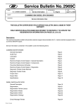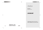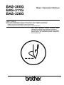
1
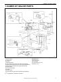
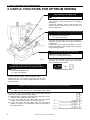
BAS-300G
BAS-311G
BAS-326G
Basic Operation Manual
DIRECT DRIVE
PROGRAMMABLE ELECTRONIC PATTERN SEWER
Please read this manual before using the machine.
Please keep this manual within easy reach for quick reference.
This basic operation manual describes basic
operations including sewing machine operations.
For cleaning, standard adjustments and more details,
please refer to the instruction manual contained in
the Document CD.
Thank you very much for buying a BROTHER sewing machine. Before using your new machine,
please read the safety instructions below and the explanations given in the instruction manual.
With industrial sewing machines, it is normal to carry out work while positioned directly in front of
moving parts such as the needle and thread take-up lever, and consequently there is always a
danger of injury that can be caused by these parts. Follow the instructions from training personnel
and instructors regarding safe and correct operation before operating the machine so that you will
know how to use it correctly.
BAS-300G, BAS-311G, BAS-326G
SAFETY INSTRUCTIONS
[1] Safety indications and their meanings
This instruction manual and the indications and symbols that are used on the machine itself are provided in order to ensure
safe operation of this machine and to prevent accidents and injury to yourself or other people.
The meanings of these indications and symbols are given below.
Indications
DANGER
The instructions which follow this term indicate situations where failure to follow the
instructions will result in death or serious injury.
WARNING
The instructions which follow this term indicate situations where failure to follow the
instructions could result in death or serious injury.
CAUTION
The instructions which follow this term indicate situations where failure to follow the
instructions may result in minor or moderate injury.
Symbols
・・・・・・
This symbol (
) indicates something that you should be careful of. The picture inside the triangle
indicates the nature of the caution that must be taken.
(For example, the symbol at left means “beware of injury”.)
・・・・・・
This symbol (
・・・・・・
This symbol (
) indicates something that you must do. The picture inside the circle indicates the
nature of the thing that must be done.
(For example, the symbol at left means “you must make the ground connection”.)
) indicates something that you must not do.
BAS-300G, BAS-311G, BAS-326G
i
[2] Notes on safety
DANGER
Wait at least 5 minutes after turning off the power switch and disconnecting the power cord from the wall outlet
before opening the cover of the control box. Touching areas where high voltages are present can result in severe
injury.
WARNING
Do not allow any liquids to get onto this sewing machine, otherwise fire, electric shocks or operating problems may
occur.
If any liquid gets inside the sewing machine (machine head or control box), immediately turn off the power and
disconnect the power plug from the electrical outlet, and then contact the place of purchase or a qualified
technician.
CAUTION
Environmental requirements
Use the sewing machine in an area which is free from
sources of strong electrical noise such as electrical
line noise or static electric noise.
Sources of strong electrical noise may cause
problems with correct operation.
Any fluctuations in the power supply voltage should
be within ±10% of the rated voltage for the machine.
Voltage fluctuations which are greater than this may
cause problems with correct operation.
The power supply capacity should be greater than the
requirements for the sewing machine's power
consumption.
Insufficient power supply capacity may cause
problems with correct operation.
The pneumatic delivery capability should be greater
than the requirements for the sewing machine's total
air consumption.
Insufficient pneumatic delivery capability may cause
problems with correct operation.
The ambient temperature should be within the range
of 5°C to 35°C during use.
Temperatures which are lower or higher than this
may cause problems with correct operation.
The relative humidity should be within the range of
45% to 85% during use, and no dew formation should
occur in any devices.
Excessively dry or humid environments and dew
formation may cause problems with correct operation.
In the event of an electrical storm, turn off the power
and disconnect the power cord from the wall outlet.
Lightning may cause problems with correct operation.
Installation
Machine installation should only be carried out by a
qualified technician.
Contact your Brother dealer or a qualified electrician
for any electrical work that may need to be done.
The sewing machine weighs approximately 88 kg.
The installation should be carried out by two or more
people.
Do not connect the power cord until installation is
complete. If the foot switch is depressed by mistake,
the sewing machine might start operating and injury
could result.
Hold the machine head with both hands when tilting it
back or returning it to its original position.
Furthermore, do not apply excessive force when
tilting back the machine head. The sewing machine
may become unbalanced and fall down, and serious
injury or damage to the sewing machine may result.
Be sure to connect the ground. If the ground
connection is not secure, you run a high risk of
receiving a serious electric shock, and problems with
correct operation may also occur.
ii
All cords should be secured at least 25 mm away
from any moving parts. Furthermore, do not
excessively bend the cords or secure them too firmly
with staples, otherwise there is the danger that fire or
electric shocks could occur.
Install the safety covers to the machine head and
motor.
If using a work table which has casters, the casters
should be secured in such a way so that they cannot
move.
Be sure to wear protective goggles and gloves when
handling the lubricating oil and grease, so that they
do not get into your eyes or onto your skin. If the oil
and grease get into your eyes or onto your skin,
inflammation can result.
Furthermore, do not drink or eat the lubricating oil or
grease. They may cause diarrhea or vomiting.
Keep the oil out of the reach of children.
BAS-300G, BAS-311G, BAS-326G
CAUTION
Sewing
This sewing machine should only be used by
operators who have received the necessary training
in safe use beforehand.
If using a work table which has casters, the casters
should be secured in such a way so that they cannot
move.
The sewing machine should not be used for any
applications other than sewing.
Attach all safety devices before using the sewing
machine. If the machine is used without these
devices attached, injury may result.
Be sure to wear protective goggles when using the
machine.
If goggles are not worn, there is the danger that if a
needle breaks, parts of the broken needle may enter
your eyes and injury may result.
Turn off the power switch at the following times. If the
foot switch is depressed by mistake, the sewing
machine might start operating and injury could result.
• When threading the needle
• When replacing the bobbin and needle
• When not using the machine and when leaving the
machine unattended
Do not touch any of the moving parts or press any
objects against the machine while sewing, as this
may result in personal injury or damage to the
machine.
If an error occurs in machine operation, or if abnormal
noises or smells are noticed, immediately turn off the
power switch. Then contact your nearest Brother
dealer or a qualified technician.
If the machine develops a problem, contact your
nearest Brother dealer or a qualified technician.
Cleaning
Turn off the power switch before carrying out
cleaning. If the foot switch is depressed by mistake,
the sewing machine might start operating and injury
could result.
Be sure to wear protective goggles and gloves when
handling the lubricating oil and grease, so that they
do not get into your eyes or onto your skin. If the oil
and grease get into your eyes or onto your skin,
inflammation can result.
Furthermore, do not drink or eat the lubricating oil or
grease. They may cause diarrhea or vomiting.
Keep the oil out of the reach of children.
Maintenance and inspection
Maintenance and inspection of the sewing machine
should only be carried out by a qualified technician.
Ask your Brother dealer or a qualified electrician to
carry out any maintenance and inspection of the
electrical system.
Turn off the power switch and disconnect the power
cord before carrying out the following operations. If
the foot switch is depressed by mistake, the sewing
machine might start operating and injury could result.
• Inspection, adjustment and maintenance
• Replacing consumable parts such as the rotary
hook
Disconnect the air hoses from the air supply and wait
for the needle on the pressure gauge to drop to “0”
before carrying out inspection, adjustment and repair
of any parts which use the pneumatic equipment.
Hold the machine head with both hands when tilting it
back or returning it to its original position.
Furthermore, do not apply excessive force when
tilting back the machine head. The sewing machine
may become unbalanced and fall down, and serious
injury or damage to the sewing machine may result.
If the power switch needs to be left on when carrying
out some adjustment, be extremely careful to observe
all safety precautions.
When replacing parts and installing optional
accessories, be sure to use only genuine Brother
parts.
Brother will not be held responsible for any accidents
or problems resulting from the use of non-genuine
parts.
If any safety devices have been removed, be
absolutely sure to re-install them to their original
positions and check that they operate correctly before
using the machine.
To prevent accidents and problems, do not modify
the machine yourself.
Brother will not be held responsible for any accidents
or problems resulting from modifications made to the
machine.
BAS-300G, BAS-311G, BAS-326G
iii
[3] Warning labels
The following warning labels appear on the sewing machine.
Please follow the instructions on the labels at all times when using the machine. If the labels have been removed or are
difficult to read, please contact your nearest Brother dealer.
1
2
.
*Safety devices
Devices such as eye guard, finger guard, thread take-up
cover, motor cover, tension release solenoid cover, inner
cover, outer cover, fixed cover and gas spring support cover
iv
3
Be careful not to get your hand caught when tilting back the machine head and returning it to its
original position.
4
Be sure to connect the ground. If the ground connection is not secure, you run a high risk of receiving
a serious electric shock, and problems with correct operation may also occur.
5
Direction of operation
BAS-300G, BAS-311G, BAS-326G
Tension release solenoid cover
Motor cover
Inner cover L
Outer cover
Fixed cover L
Motor cover L
Thread take-up cover
Inner cover R
Eye guard
Outer cover
Fixed cover R
Motor cover R
Finger guard
Gas spring support cover
2960B
2961B
BAS-300G, BAS-311G, BAS-326G
v
CONTENTS
1. NAMES OF MAJOR PARTS ................ 1
2. USEFUL FUNCTIONS FOR
OPTIMUM SEWING .............................. 2
3. INSTALLATION .................................... 3
3-1. Table processing diagram ................................ 4
3-2. Installing the control box................................... 5
3-3. Installing the oil pan.......................................... 5
3-4. Installing the machine head.............................. 6
3-5. Tilting the sewing machine head ...................... 9
3-6. Installing the operation panel............................ 10
3-7. Installing the treadle unit
(motor-driven work clamp specifications) ......... 11
3-8. Installing the two-pedal foot switch
(pneumatic work clamp specifications) .............. 11
3-9. Connecting the cords........................................ 12
3-10. Connecting the ground wire............................ 14
3-11. Connecting the power cord............................. 15
3-12. Installing the cotton stand............................... 15
3-13. Installing the pneumatic unit
(pneumatic work clamp specifications) ............ 16
3-14. Installing the eye guard .................................. 17
3-15. Installing the motor cover ............................... 17
3-16. Lubrication ...................................................... 18
5. USING THE OPERATION PANEL
(BASIC OPERATIONS) ....................... 25
5-1. Name and function of each operation
panel item..........................................................25
5-2. Loading sewing data .........................................27
5-3. Setting the program number .............................27
5-4. Setting the X-scale and Y-scale........................28
5-5. Setting the sewing speed..................................28
5-6. Checking the sewing pattern.............................29
5-7. Setting the work clamp lift amount ....................30
5-8. Notes on handling CF cards (sold separately) ...32
6. SEWING ............................................... 33
6-1. Sewing ..............................................................33
6-2. Using the STOP switch .....................................34
6-3. Using the thread wiper switch ...........................34
Document CD ........................................... 36
4. PREPARATION BEFORE SEWING..... 19
4-1. Installing the needle.......................................... 19
4-2. Threading the upper thread .............................. 19
4-3. Winding the lower thread.................................. 21
4-4. Installing the bobbin case ................................. 22
4-5. Thread tension.................................................. 23
4-5-1. Lower thread tension.............................. 23
4-5-2. Upper thread tension.............................. 23
4-6. Home position detection ................................... 24
BAS-300G, BAS-311G, BAS-326G
1. NAMES OF MAJOR PARTS
1. NAMES OF MAJOR PARTS
<BAS-300G>
<BAS-311G>
<BAS-326G>
Two-pedal foot switch
2962B
(1) Power switch
(2) Control box
(3) CF slot
(4) Operation panel
(5) Foot switch (motor-driven work clamp specifications)
(6) Work clamp switch (pneumatic work clamp specifications)
(7) Start switch (pneumatic work clamp specifications)
(8) STOP switch
(9) Thread wiper switch
(10) Pulley
(11) Cotton stand
(12) Solenoid valve (pneumatic work clamp specifications)
TM
CF
Safety devices:
(13) Finger guard
(14) Eye guard
(15) Thread take-up cover
(16) Motor cover
is a trademark of SanDisk Corporation.
BAS-300G, BAS-311G, BAS-326G
1
2. USEFUL FUNCTIONS FOR OPTIMUM SEWING
2. USEFUL FUNCTIONS FOR OPTIMUM SEWING
Easy threading in threading mode
Page 20
When using threading mode for threading, the tension
discs will open so that the thread can be threaded
more easily.
Furthermore, threading mode is safe because the
sewing machine will not start even when the foot
switch is depressed.
Presser foot height can be set easily using the panel
Page 30
INSTRUCTION MANUAL CD
6-7. Using user programs
The height of the presser foot can be set simply by
entering a numeric value at the panel, without the
need for tools.
Furthermore, you can use user programs to set the
presser foot height to the desired height separately
for each sewing program.
Easy and accurate feed plate replacement
INSTRUCTION MANUAL CD
10-11-1. Installing the feed plate
2376B
The feed plate installation position can be obtained
accurately by using the panel, which makes feed
plate replacement much easier.
The work clamp lift amount can be set easily
using the panel (motor-driven work clamp specifications)
Page 30
INSTRUCTION MANUAL CD
6-7. Using user programs
Feed plate installation mode
The work clamp lift amount can be set simply by entering a
numeric value at the panel, without the need for tools.
Furthermore, you can use user programs to set the work
clamp lift amount to the desired height separately for each
sewing program.
3 types of work clamp lowering operation (motor-driven work clamp specifications)
INSTRUCTION MANUAL CD
6-2. Setting memory switches, 6-3. List of memory switch settings
You can select one of three different types of work clamp lowering
operation by changing memory switch settings.
[1] Analog dropping, where the work clamp drops smoothly in direct
proportion to the pedal depression amount
[2] 1 step drop, where the work clamp drops from the highest
position A to the lowest position C in a single movement
[3] 2 step drop, where the work clamp drops from the highest
position A to pause at an intermediate position B, then drops to
the lowest position C.
5029Q
2
BAS-300G, BAS-311G, BAS-326G
3. INSTALLATION
3. INSTALLATION
CAUTION
Machine installation should only be carried out by a
qualified technician.
Contact your Brother dealer or a qualified electrician
for any electrical work that may need to be done.
The sewing machine head weighs approximately
88kg. The installation should be carried out by two or
more people.
Do not connect the power cord until installation is
complete.
If the foot switch is depressed by mistake, the sewing
machine might start operating and injury could result.
All cords should be secured at least 25 mm away from
any moving parts. Furthermore, do not excessively
bend the cords or secure them too firmly staples,
otherwise there is the danger that fire or electric
shocks could occur.
Be sure to connect the ground. If the ground
connection is not secure, you run a high risk of
receiving a serious electric shock, and problems with
correct operation may also occur.
Install the safety covers to the machine head and
motor.
Hold the machine head with both hands when tilting it
back or returning it to its original position.
Furthermore, do not apply excessive force when tilting
back the machine head. The sewing machine may
become unbalanced and fall down, and serious injury
or damage to the sewing machine may result.
BAS-300G, BAS-311G, BAS-326G
3
3. INSTALLATION
3-1. Table processing diagram
• The thickness of the table should be at least 40 mm, and it should be strong enough to bear the weight and vibration of the
sewing machine.
• If the distance A between the insides of the legs is less than 740 mm, move the control box installation position to the left (B =
261mm).
• Check that the control box is at least 10 mm away from the leg. If the control box and the leg are too close together, it may result
in incorrect sewing machine operation.
<For BAS-311G and 326G>
3000B
(Reference position)
<For BAS-300G>
Only the holes for installing the operation panel and
the hole for the cord differ from the above diagram.
Refer to the diagram above for all other dimensions.
* The operation panel can be moved to any
preferred position as long as it is in a position
where the cord reaches the PCB inside the
control box.
3003B
4
BAS-300G, BAS-311G, BAS-326G
3. INSTALLATION
3-2. Installing the control box
Remove the eight screws (1), and then
remove the control box cover (2).
(3) Control box
(4) Bolts [4 pcs.]
(5) Plain washers [4 pcs.]
(6) Spring washers [4 pcs.]
(7) Nuts [8 pcs.]
1840B
(8) Power switch
(9) Wood screws [2 pcs.]
(10) Staples [4 pcs.]
Operator
1841B
3-3. Installing the oil pan
For
motor-driven
work
clamp
specifications, install the treadle unit
mounting bolt (A) before installing the
oil pan.
(Refer to "3-7. Installing the treadle unit
(motor-driven
work
clamp
specifications)".)
(1)
(2)
(3)
(4)
Oil pan
Nails [7 pcs.]
Rubber cushions [4 pcs.]
Waste oil tank
4911Q
BAS-300G, BAS-311G, BAS-326G
5
3. INSTALLATION
3-4. Installing the machine head
(1) Pins [2 pcs.]
(2) Set screws [2 pcs.]
(3) Hinge rubber assemblies [2 pcs.]
Place the machine head gently on top of
the oil pan and the rubber cushions.
Pulse motor
Approx. 20 mm
NOTE:
• Be careful not to get the cords
clamped between the machine head
and the oil pan.
• When holding the machine head, do
not hold it by the pulse motor. This
may cause problems with operation
of the pulse motor.
Approx. 20 mm
2966B
(4)
(5)
(6)
(7)
(8)
(9)
4913Q
6
BAS-300G, BAS-311G, BAS-326G
Hinge holders [2 pcs.]
Bolts [4 pcs.]
Plain washers [4 pcs.]
Nuts [4 pcs.]
Head rest
Bolts with washer [4 pcs.]
3. INSTALLATION
<BAS-300G>
2698B
<BAS-300G>
(10) Auxiliary plate
(11) Bolts with washer [4 pcs.]
Loosen the four bolts with washer (11),
and adjust so that the auxiliary plate (10)
is 0 to 0.5 mm above the needle plate.
Needle plate
NOTE:
Install the auxiliary plate (10) so that it
is horizontal.
If the auxiliary plate (10) is lower than
the needle plate, the feed plate may
get caught on the needle plate.
<BAS-311G, 326G>
<BAS-311G, 326G>
(10) Auxiliary plate
(11) Bolts with washer [10 pcs.]
Loosen the six bolts with washer (11) and
the four bolts with washer (12), and adjust
so that the auxiliary plate (10) is 0 to 0.5
mm above the needle plate.
Needle plate
NOTE:
Install the auxiliary plate (10) so that it
is horizontal.
If the auxiliary plate (10) is lower than
the needle plate, the feed plate may
get caught on the needle plate.
2697B
Move the work clamp arm all the way to
the right when looking from the front of
the sewing machine (the direction of the
arrow in the illustration), and then gently
tilt back the machine head.
Work clamp arm
NOTE:
Two or more people should tilt back the
machine head, and it should be tilted
gently while being held with both
hands.
2969B
BAS-300G, BAS-311G, BAS-326G
7
3. INSTALLATION
Be sure to install so
that the side with “UP”
on it is facing upward.
(13) Gas spring holders [2 pcs.]
(14) Spacer
(15) Bolt
(16) Nut
(17) Gas spring
(18) Shaft collars [2 pcs.]
(19) Gas spring shaft D
(20) Plain washers [2 pcs.]
(21) Retaining rings E [2 pcs.]
(22) Bolts [2 pcs.]
(23) Plain washers (medium) [2 pcs.]
(24) Plain washers (large) [2 pcs.]
(25) Spring washers [2 pcs.]
(26) Nuts [2 pcs.]
(27) Gas spring shaft U
(28) Set screw
NOTE:
For
motor-driven
work
clamp
specifications, the bolts (22), plain
washers (23), plain washers (24),
spring washers (25) and nuts (26) in
the places marked with * are also used
to install the treadle unit. (Refer to "3-7.
Installing the treadle unit (motor-driven
work clamp specifications)".)
1902B
(29) Gas spring support cover
(30) Bolts with washer [6 pcs.]
4916Q
8
BAS-300G, BAS-311G, BAS-326G
3. INSTALLATION
Figure 1
Oil pan
2365B
• Gently return the machine head to its original position.
• Loosen the screw (31). Move the machine head switch (32) to the position shown in the illustration, and then secure the machine
head switch (32) with the screw (31) and the accessory M3x16 screw (33).
• Check that the machine head switch (32) is turned on as shown in figure 1.
NOTE:
If the machine head switch is not turned on, errors "E050", "E051" and "E055" will be generated.
3-5. Tilting the sewing machine head
CAUTION
2970B
4919Q
1. Move the work clamp arm (1) as far as it will go in the direction of the arrow in the illustration (to the right when looking from the
front of the sewing machine).
2. Stand at the left side of the table, and gently tilt the machine head towards you.
NOTE:
Always be sure to move the work clamp arm (1) all the way to the right before tilting back the machine head. If you try to tilt back
the machine head while the work clamp arm (1) is still on the left side, it may damage the outer cover L (2).
BAS-300G, BAS-311G, BAS-326G
9
3. INSTALLATION
3-6. Installing the operation panel
<BAS-300G>
2971B
<BAS-300G>
(1)
(2)
(3)
(4)
(5)
Operation panel set
Panel rubber
Plain washers [6 pcs.]
Bolts [3 pcs.]
Nuts [6 pcs.]
• Insert the cord from the operation
panel (1) which has been passed
through the hole in the table into the
control box through the hole in the side
of the control box.
(6) Staples [3 pcs.]
<BAS-311G, 326G>
<BAS-311G, 326G>
(1)
(2)
(3)
(4)
(5)
(6)
(7)
Operation panel base
Cushion A
Plain washers (medium) [3 pcs.]
Bolts [3 pcs.]
Cushions B [3 pcs.]
Plain washers (large) [3 pcs.]
Nuts [6 pcs.]
Tighten until the thickness of cushion B
(5) is about 1 mm.
(8) Operation panel
(9) Operation panel stand
(10) Bolts [3 pcs.]
(11) Rubber seat
(12) Bolt
• Pass the cord from the operation panel
(8) through the operation panel stand
(9) and the rubber seat (11).
• Fit the operation panel stand (9) into
the operation panel base (1), and then
secure it with the bolt (12).
• Pass the cord from the operation panel
(8) through the hole in the table, and
then insert it into the control box
through the hole in the side of the
control box.
(13) Staples [3 pcs.]
4920Q
10
BAS-300G, BAS-311G, BAS-326G
3. INSTALLATION
3-7. Installing the treadle unit (motor-driven work clamp specifications)
(1)
(2)
(3)
(4)
(5)
Treadle unit
Bolts [3 pcs.]
Plain washers [3 pcs.]
Spring washers [3 pcs.]
Nuts [3 pcs.]
NOTE:
• Install the bolt for mounting hole A before installing the oil
pan. (Refer to “3-3. Installing the oil pan.”)
• Mounting hole B is used to install the gas spring supports
with the bolt, plain washer, spring washer and nut. (Refer
to "3-4. Installing the machine head".)
* Use a commercially-available foot switch and connecting rod.
* If changing the mounting position for the treadle unit, use the
accessory bolts, plain washers, spring washers and nuts.
<Foot switch operating method>
When the foot switch is depressed to the 1st step, the work
clamp is lowered, and when it is depressed to the 2nd step, the
sewing machine starts sewing.
1st step
2nd step
4441Q
4921Q
3-8. Installing the two-pedal foot switch (pneumatic work clamp specifications)
(1) Foot switch
Insert the connector for the foot switch (1) into P6 (FOOT) on
the main PCB. (Refer to "3-9. Connecting the cords".)
* Be sure to make the ground connection. (Refer to “3-10.
Connecting the ground wire”.)
<Foot switch operating method>
When the work clamp switch (left) is depressed, both work
clamps are lowered, and when the start switch (right) is
depressed, the sewing machine starts sewing.
* The work clamp lowering method can be changed using
memory switch No. 002. (Refer to “6-3. List of memory
switch settings” in the instruction manual CD.)
Work clamp switch (2-step)
Start switch
2972B
BAS-300G, BAS-311G, BAS-326G
4923Q
11
3. INSTALLATION
3-9. Connecting the cords
1. Gently tilt back the machine head.
2. Pass the cord bundle through the hole
in the work table.
3. Loosen the two screws (1), and then
open the cord presser plate (2) in the
direction of the right arrow and pass
the cord bundle through the opening.
4. Securely connect the connectors as
indicated in the table below.
NOTE:
• Check that the connector is facing
the correct way, and then insert it
firmly until it locks into place.
• Secure the cables with cable ties
and cord clamps, while being careful
not to pull on the connector.
4924Q
<Main PCB>
NOTE:
• Check that the connector is facing the correct
way, and then insert it firmly until it locks into
place.
• Secure the cables with cable ties and cord
clamps, while being careful not to pull on the
connector.
*1
: Be sure to make the ground connection.
(Refer to "3-10. Connecting the ground
wire".)
Lock the cord
clamp securely.
Connector
1842B
X pulse motor encoder 5-pin white
Y pulse motor encoder 5-pin blue
Work clamp pulse motor encoder 5-pin black
Foot switch 10-pin
Operation panel 8-pin
Machine head switch 3-pin
Home position sensor assembly 12-pin
STOP switch 6-pin
Valve harness 12-pin (pneumatic work clamp
specifications)
Programmer relay harness 8-pin
Solenoid selection harness 4-pin
Connection location on
main PCB
P20 (X-ENC)
P4 (Y-ENC)
P5 (P-ENC)
P6 (FOOT)
P1 (PANEL)
P9 (HEAD-SW)
P8 (SENSOR1)
P13 (HEAD)
P12 (AIR1)
P7 (PRG)
P3(CUTTER)
Cord clamp
(3)
(3)
(3)
(3)
(3)
(4)
(4)
(4)
(4)
(3)
-
(Continued on next page)
12
BAS-300G, BAS-311G, BAS-326G
3. INSTALLATION
<Power supply motor PCB>
<Removing>
Press
the tab.
<Securing>
<PMD PCB>
NOTE:
Route the X, Y and work clamp pulse motor
harnesses so that they do not touch the
PMD PCB.
*1
: Be sure to make the ground connection.
(Refer to "3-10. Connecting the ground
wire".)
Connector
Cord clamp/cable tie
Machine head memory 7-pin
P3 (HEAD-M)
Upper shaft motor 3-pin
P4 (UVW)
(5)
Synchronizer 14-pin
P5 (SYNC)
(5), (6)
Connector
1843B
Connection location on
power supply motor PCB
Connection location on
PMD PCB
(4)
Cable tie
Work clamp pulse motor 4-pin black
P3 (PPM)
(5), (6)
Thread trimmer solenoid 6-pin
P6 (SOL1)
(5), (6)
Tension release solenoid 4-pin
Y pulse motor 4-pin blue
P7 (SOL2)
P8 (YPM)
(5), (6)
(5), (6)
X pulse motor 4-pin white
P10 (XPM)
(5), (6)
(Continued on next page)
BAS-300G, BAS-311G, BAS-326G
13
3. INSTALLATION
5. Close the cord presser plate (2) in the direction of the left
arrow, and secure it by tightening the two screws (1).
Note: Close the cord presser plate (2) securely so that no
foreign objects, insects or small animals can get inside
the control box.
6. Check that the cords do not get pulled, and then gently
return the machine head to its original position.
4927Q
3-10. Connecting the ground wire
CAUTION
Be sure to connect the ground. If the ground connection is not secure, you run a high risk of receiving a serious electric
shock, and problems with correct operation may also occur.
2973B
(1)
(2)
(3)
(4)
Ground wire from upper shaft motor harness
Ground wire from the machine head
Ground wire from operation panel
Ground wires from two-pedal foot switch harnesses (2 wires) [for pneumatic work clamp specifications only]
• Tighten the control box cover with the eight screws. Check that the cords are not clamped by the cover at this time.
NOTE: Make sure that the ground connections are secure in order to ensure safety.
14
BAS-300G, BAS-311G, BAS-326G
3. INSTALLATION
3-11. Connecting the power cord
1. Attach an appropriate plug to the
power cord (1). (The green and yellow
wire is the ground wire.)
2. Insert
the
plug
into
a
properly-grounded AC power supply.
* The inside of the control box uses
single-phase power.
NOTE:
Do not use an extension cord. If this is
not observed, it may cause problems
with correct operation.
<Single-phase
specifications>
Green and yellow wire
(ground wire)
<Three-phase
specifications>
Green and yellow wire
(ground wire)
5239Q
3-12. Installing the cotton stand
(1) Cotton stand
NOTE:
Fit the washer (2), and then securely
tighten the nut (3) so that the cotton
stand does not move.
2974B
BAS-300G, BAS-311G, BAS-326G
15
3. INSTALLATION
3-13. Installing the pneumatic unit (pneumatic work clamp specifications)
Install underneath the work table.
(1)
(2)
(3)
(4)
Solenoid valve assembly
Washers [2 pcs.]
Wood screws [2 pcs.]
Rubber hose
After installing the pneumatic unit, adjust
the air pressure.
(Refer to “10-16. Adjusting the air
pressure” in the instruction manual CD.)
NOTE:
Make sure that the pneumatic unit
does not touch the control box or the
work table leg.
1904B
Connect each air tube to the position with the corresponding number.
Cylinder R
Cylinder L
Upper knob
Lower knob
Manual button
<Adjusting the speed controller>
You can use the valve knobs to adjust the lifting and lowering speeds.
The valve knobs should be adjusted so that the left and right sides of the work clamp operate at the same speed.
• When the upper knob is tightened, the lifting speed becomes slower. When it is loosened, the lifting speed becomes faster.
• When the lower knob is tightened, the lowering speed becomes slower. When it is loosened, the lowering speed becomes
faster.
You can operate the work clamp while the power is turned off by pressing the manual button.
16
BAS-300G, BAS-311G, BAS-326G
5220Q
1905B
3. INSTALLATION
3-14. Installing the eye guard
CAUTION
Attach all safety devices before using the sewing machine.
If the machine is used without these devices attached, injury may result.
(1)
(2)
(3)
(4)
(5)
Screw (loosen)
Eye guard (tilt forward)
Eye guard assembly
Plain washers [2 pcs.]
Screws [2 pcs.]
After installing the eye guard assembly
(3), return the eye guard (2) to its original
angle, and then tighten the screw (1) to
secure it in place
2367B
3-15. Installing the motor cover
2975B
(1)
(2)
(3)
(4)
(5)
(6)
Motor cover R
Screws [4 pcs.]
Motor cover L
Screws [4 pcs.]
Motor cover
Screws [4 pcs.]
NOTE:
Be careful not to clamp the cords when
installing the motor cover.
2976B
BAS-300G, BAS-311G, BAS-326G
17
3. INSTALLATION
3-16. Lubrication
CAUTION
Do not connect the power cord until lubrication is complete.
If the foot switch is depressed by mistake, the sewing machine might start operating and injury could result.
Be sure to wear protective goggles and gloves when handling the lubricating oil and grease, so that they do not get into
your eyes or onto your skin. If the oil and grease get into your eyes or onto your skin, inflammation can result.
Furthermore, do not drink or eat the lubricating oil or grease. They may cause diarrhea or vomiting.
Keep the oil out of the reach of children.
The sewing machine should always be lubricated and the oil supply replenished before it is used for the first time, and also after
long periods of non-use.
Use only the lubricating oil <JX Nippon Oil & Energy Corporation Sewing Lube 10N; VG10> specified by Brother.
* If this type of lubricating oil is difficult to obtain, the recommended oil to use is <Exxon Mobil Essotex SM10; VG10>.
2368B
5221Q
1. Fill the arm-side oil tank with oil.
2. Move the work clamp arm (1) as far as it will go to the right when looking from the front of the sewing machine, and then slide the
outer cover L (2) into the inner cover L (3) so that the lubrication hole in the bed is visible. Pour oil into the bed side oil tank
through this hole.
NOTE:
Be sure to fill the machine with oil when the oil level is down to about one-third full in the oil sight glass. If the oil drops below the
one-third level, there is the danger that the machine may seize during operation.
<Standard parts>
・ BAS-300G-03[]
・ BAS-311G
・ BAS-326G
<Option parts>
・ BAS-300G-01[]
・ BAS-300G-02[]
1845B
4940Q
3. Pour oil in through the two holes of the shuttle race base assembly so that the felt (4) is lightly moistened.
NOTE:
・ The two pieces of felt (4) should normally project by 0 to 0.5 mm from the hook race. Be careful not to push in the felt (4)
when lubricating.
・ If there is no more oil on the felt (4) of the shuttle race base assembly, problems with sewing may result.
2
4. If using the needle cooler (5), fill it with silicon oil (100 mm /s). (Refer to “4-2. Threading the upper thread”.)
18
BAS-300G, BAS-311G, BAS-326G
4. PREPARATION BEFORE SEWING
4. PREPARATION BEFORE SEWING
4-1. Installing the needle
CAUTION
Turn off the power switch before installing the needle.
If the foot switch is depressed by mistake, the sewing machine might start operating and injury could result.
1. Loosen the set screw (1).
2. Insert the needle (2) in a straight line as far as it will go,
making sure that the long groove on the needle is at the
front, and then securely tighten the set screw (1).
2369B
4-2. Threading the upper thread
Thread the upper thread correctly as shown in the illustration below.
* When using threading mode for threading, the tension discs (1) will open so that the thread can be threaded more easily.
(Refer to following page.)
2977B
[If using cotton thread or spun thread]
[If using synthetic thread]
<Standard parts>
BAS-300G-03[], BAS-311G, BAS-326G
<Option parts>
BAS-300G-01[], 02[]
Thread the
upper thread
Needle cooler
2978B
2370B
• Turn the machine pulley (2) and raise the thread take-up (3) to its highest position before threading the upper thread.
(This will make threading easier and it will prevent the thread from coming out at the sewing start.)
• When threading the thread through the needle, allow a distance of approximately 40 mm between the needle hole and the
end of the thread.
If the trailing length of the thread is too long, it may cause the thread to become tangled.
BAS-300G, BAS-311G, BAS-326G
19
4. PREPARATION BEFORE SEWING
<Threading mode>
Threading mode is safe because the sewing machine will not start even when the foot switch is depressed.
1
Turn on the power switch.
4421Q
2
Press the THREAD/CLAMP key.
All indicators switch off
• The work clamp will drop.
• The tension discs will open.
3
4
THREAD/CLAMP indicator illuminates
MENU indicator switches off
Threading the thread.
• When 5 minutes have passed, the buzzer will sound and the tension discs will close.
Ending threading mode
Press the THREAD/CLAMP key.
• The work clamp will return to where it was before
threading mode was started.
THREAD/CLAMP indicator switches off
20
4427Q
BAS-300G, BAS-311G, BAS-326G
4. PREPARATION BEFORE SEWING
4-3. Winding the lower thread
CAUTION
Do not touch any of the moving parts or press any objects against the machine while winding the lower thread.
Injury or damage to the sewing machine may result.
1. Place the bobbin onto the bobbin winder shaft (1).
2. Thread the thread as shown in the illustration, wind the
thread around the bobbin several times, and then press
the bobbin presser arm (2).
3. Turn on the power switch.
4. Depress the foot switch to the 2nd step.
(If using a two-pedal foot switch, lower the work clamp
before depressing the start switch.)
The feed mechanism will move to the home position.
5. Check that the needle does not touch the work clamp,
and then while pressing the TENSION/WIND key (3),
depress the foot switch to the 2nd step.
(If using a two-pedal foot switch, lower the work clamp
before depressing the start switch.)
6. Release the TENSION WIND key (3) after the machine
starts operating, and keep depressing the foot switch
until the lower thread stops being wound onto the
bobbin.
(If you release the foot switch before winding is
complete, and then depress it again while pressing the
TENSION/ WIND key (3), winding will start again.)
7. Once winding of the set amount of lower thread (80 90% of the bobbin capacity) is completed, the bobbin
presser arm (2) will return automatically.
8. Remove the bobbin, hook the thread onto the knife (4),
and then pull the bobbin in the direction of the arrow to
cut the thread.
4429Q
4430Q
4431Q
Adjusting the bobbin winding amount
Loosen the screw (5) and move the bobbin presser (6) to
adjust.
4432Q
For case A
If the thread winds onto the bobbin unevenly
Loosen the set screw (7) and move the bobbin winder
tension assembly (8) up and down to adjust.
* For case A, move the bobbin winder tension assembly
(8) down, and for case B, move it upward.
For case B
4471Q
BAS-300G, BAS-311G, BAS-326G
21
4. PREPARATION BEFORE SEWING
4-4. Installing the bobbin case
CAUTION
Turn off the power switch before installing the bobbin case.
If the foot switch is depressed by mistake, the sewing machine might start operating and injury could result.
2534Q
30mm
4945Q
1.
2.
3.
4.
5.
6.
2535Q
Pull the shuttle race cover (1) downward to open it.
While holding the bobbin so that the thread winds to the right, insert the bobbin into the bobbin case.
Pass the thread through the slot (2) and pull it out from the thread hole (3).
Check that the bobbin turns in the direction of the arrow when the thread is pulled.
Pass the thread through the lever thread hole (4), and then pull out approximately 30 mm of thread.
Hold the latch on the bobbin case and insert the bobbin case into the rotary hook.
22
BAS-300G, BAS-311G, BAS-326G
4. PREPARATION BEFORE SEWING
4-5. Thread tension
[Thread tension reference]
Specifications
Heavy-weight materials
(-01[])
Medium-weight materials
(-02[])
Seatbelt (-03[])
Upper thread
#20 or similar
#50 or similar
#4 or similar
Lower thread
#20 or similar
#50 or similar
#4 or similar
Upper thread tension (N)
1.4 − 1.8
0.8 − 1.2
1.2 − 2.0
0.2 − 0.3
Lower thread tension (N)
1.0 − 1.5
Pre-tension (N)
0.1 − 0.6
0.1 − 0.3
0.3 − 0.6
Needle
DP x 17 #19
DP x 5 #16
DP x 17 #25
Normal sewing speed
2,000 sti/min
2,000 sti/min
1,300 sti/min
4-5-1. Lower thread tension
Adjust the thread tension to the weakest possible tension by
turning the thread tension nut (1) until the bobbin case will
not drop by its own weight while the thread end coming out
of the bobbin case is held.
Stronger
Weaker
2536Q
4-5-2. Upper thread tension
1. Turn the tension nut (1) (main tension) to adjust the
tension as appropriate for the material being sewn.
2. Use the tension nut (2) (sub tension) to adjust the upper
thread trailing length to about 40 mm.
Stronger
Weaker
Stronger
Weaker
2153B
BAS-300G, BAS-311G, BAS-326G
23
4. PREPARATION BEFORE SEWING
4-6. Home position detection
2979B
Before starting home position detection, check that the
needle bar is at its highest position.
Turn the pulley (1) in the direction of the arrow until the
ridge at the bottom of the thread take-up (2) is aligned with
the processed line on the arm.
Aligned
5223Q
4421Q
1. Turn on the power switch.
The power indicator (3) will illuminate, and the model
number will appear in the PROGRAM No. display (4)
and the specifications class will appear in the menu
display (5).
Specifications
Motor-driven work clamp
Pneumatic work clamp
[ELEC]
[ Air]
After this, the program number will flash in the
PROGRAM No. display (4).
4952Q
2nd step
2. Depress the foot switch to the 2nd step.
(If using a two-pedal foot switch, lower the work clamp
before depressing the start switch (6).)
The sewing machine will move to the home position and
the work clamp will rise.
* For programs with a large number of stitches, the
buzzer will sound after the home position is detected,
and then the feed mechanism will move to the sewing
start position.
NOTE:
If error "E110" appears when the foot switch is
depressed, turn the pulley (1) in the direction of
operation to clear the error.
4441Q
24
4953Q
BAS-300G, BAS-311G, BAS-326G
5. USING THE OPERATION PANEL (BASIC OPERATIONS)
5. USING THE OPERATION PANEL
(BASIC OPERATIONS)
5-1. Name and function of each operation panel item
4435Q
(1) Power indicator
Illuminates when the power is turned on.
(2) CAUTION indicator
Illuminates when an error occurs.
(3) RESET key
Used to reset errors.
(4) TEST key
Used to start test mode.
(5) TEST indicator
Illuminates when the TEST key (4) has been pressed.
(6) THREAD/CLAMP key
Used to start threading mode or work clamp height setting mode.
(7) THREAD/CLAMP indicator
Illuminates when the THREAD/CLAMP key (6) has been pressed.
(8) TENSION/WIND key
Used to wind the lower thread.
(9) TENSION/WIND indicator
Spare
(10) X-SCALE indicator
Illuminates when the SELECT key (15) is pressed to shown the X-scale setting.
(11) Y-SCALE indicator
Illuminates when the SELECT key (15) is pressed to shown the Y-scale setting.
(Continued on next page)
BAS-300G, BAS-311G, BAS-326G
25
5. USING THE OPERATION PANEL (BASIC OPERATIONS)
4435Q
(12) SPEED indicator
Illuminates when the SELECT key (15) is pressed to shown the sewing speed setting.
(13) COUNTER indicator
Illuminates when the SELECT key (15) is pressed to shown the lower thread or production counter setting.
(14) SPLIT No. indicator
Illuminates when the SELECT key (15) is pressed to show the split setting when split data (for specifying a pause while
the program is running) exists.
(15) SELECT key
Used to select a menu (X-scale, Y-scale, sewing speed and counter).
(16) Menu display
Displays information such as menu setting values, memory switch settings and error codes.
(17) Setting keys
Used to change the value which is displayed in the menu display (16).
In addition, it is used to move the needle position forward and back when sewing has been paused.
(18) PROGRAM No. display
Displays information such as program numbers.
(19) Setting keys
Used to change the value which is displayed in the PROGRAM No. display (18).
(20) CF media indicator
Illuminates when a CF card (external media) is inserted while the power is turned on.
(21) FD media indicator
Illuminates when a floppy disk (external media) is inserted while the power is turned on. [Option compatibility]
(22) Function keys [F1, F2, F3, F4]
Used to select user programs and to set and select cycle programs.
(23) R/W key
Used to read data from and write data to external media.
CFTM is a trademark of SanDisk Corporation.
26
BAS-300G, BAS-311G, BAS-326G
5. USING THE OPERATION PANEL (BASIC OPERATIONS)
5-2. Loading sewing data
Refer to "5-8. Notes on handling CF cards (sold separately)" for details on using CF cards.
1
With the power turned off, insert the CF card into the CF
slot.
NOTE:
• Make sure the CF card is facing the correct way
when inserting it.
• Always be sure to keep the cover closed except
when inserting and removing the CF card. If this is
not done, dust may get inside and cause problems
with operation.
4453Q
2
Turn on the power switch.
Press the
or
key to select the program number
(100 − 999).
* The "---" display is used to check the feed home
position.
4421Q
CF media indicator illuminates
3
4457Q
Press the R/W key.
• The buzzer will sound and the selected sewing data
will be loaded from the CF card and copied into the
sewing machine's internal memory.
4
Loading
Loading complete
The PROGRAM No. display will change from " P" to the selected program number.
Turn off the power switch, remove the CF card, and then close the cover of the CF slot.
4498Q
5-3. Setting the program number
1. Press the
or
key (1) to select the program number
that is loaded into the internal memory.
• The program number will flash in the PROGRAM No.
display (2).
• "---" will appear at the time of shipment from the
factory. (For checking feed home position)
2. Depress the foot switch to the 2nd step.
(If using a two-pedal foot switch, lower the work clamp
before depressing the start switch.)
• The feed mechanism will move to the home position
and the program number will be accepted.
• The program number will stop flashing and illuminate
steadily.
NOTE:
After completing the setting, be sure to refer to "5-6.
Checking the sewing pattern" to check that the needle
drop position is correct.
2nd step
4954Q
BAS-300G, BAS-311G, BAS-326G
27
5. USING THE OPERATION PANEL (BASIC OPERATIONS)
5-4. Setting the X-scale and Y-scale
The scales are set to 100 (%) at the time of shipment from
the factory.
1. Press the SELECT key (1) so that the X-SCALE
indicator (2) (for X-scale setting) or the Y-SCALE
indicator (3) (for Y-scale setting) is illuminated.
• The setting value (%) will appear in the menu display
(4).
* When memory switch no. 402 is set to "ON", the
settings will be displayed in units of mm.
2. Press the
or
key (5) to set the scale (0 − 400).
• The program number will flash in the PROGRAM No.
display (6).
3. Depress the foot switch to the 2nd step.
(If using a two-pedal foot switch, lower the work clamp
before depressing the start switch.)
• The feed mechanism will move to the home position
and the scale will be accepted.
• The program number will stop flashing and illuminate
steadily.
NOTE:
After completing the setting, be sure to refer to "5-6.
Checking the sewing pattern" to check that the needle
drop position is correct.
2nd step
4955Q
5-5. Setting the sewing speed
The sewing speed is set to 2000 (sti/min) at the time of
shipment from the factory.
1. Press the SELECT key (1) until the SPEED indicator (2)
illuminates.
• The setting value (sti/min) will appear in the menu
display (3).
2. Press the
or
key (4) to set the sewing speed.
(Sewing speed setting: 400 − 2700)
4956Q
28
BAS-300G, BAS-311G, BAS-326G
5. USING THE OPERATION PANEL (BASIC OPERATIONS)
5-6. Checking the sewing pattern
Use test feed mode to check the needle movement with only the feed mechanism operating.
Check that the needle hole does not come out from the frame of the work clamp.
1
Press the TEST key.
TEST indicator illuminates
2
Select the program number to be checked, and then set the X-scale and
the Y-scale.
• The program number will flash.
Depress the foot switch to the 2nd step.
(If using a two-pedal foot switch, lower the work clamp before depressing
the start switch.)
• The feed mechanism will move to the home position and the program
number will stop flashing and illuminate steadily.
• The number of stitches will appear in the menu display.
2nd step
3
COUNTER indicator illuminates
Starting continuous test feed mode
1st step
2nd step
4957Q
4441Q
Depress the foot switch to the 2nd step and then release it.
(If using a two-pedal foot switch, lower the work clamp before depressing
the start switch and releasing it.)
• Feed mechanism starts moving continuously one stitch at a time.
[Fast-forward test mode]
If you depress the foot switch to the 1st step while the feed mechanism is
moving, the feeding speed will become faster while the foot switch is being
depressed. (If using a two-pedal foot switch, depress the work clamp
switch.)
4441Q
4443Q
key, the feed mechanism will move
If you press the
forward one stitch at a time, and if you press the
key, the feed mechanism will move backward one
stitch at a time. (The feed will move quicker if you
keep the key pressed down.)
TEST indicator illuminates
If you would like sewing to start while test feeding is in
progress, press the TEST key to switch off the TEST
indicator.
When you depress the foot switch to the 2nd step,
sewing will start. (If using a two-pedal foot switch,
depress the start switch.)
2nd step
4441Q
TEST indicator switches off
4
If test feeding continues to the final stitch,
it will then stop.
Press the TEST key.
TEST indicator switches off
BAS-300G, BAS-311G, BAS-326G
29
5. USING THE OPERATION PANEL (BASIC OPERATIONS)
5-7. Setting the work clamp lift amount
The setting for the work clamp lift amount can be changed using the operation panel.
* For pneumatic work clamp specifications, only threading mode and intermittent presser foot height setting mode will be
available.
1
2
Press the THREAD/CLAMP key.
The sewing machine will switch to threading mode.
• " 1" will appear in the PROGRAM No. display, and the work
clamp will drop.
All indicators switch off
THREAD/CLAMP indicator illuminates
MENU indicator switches off
Motor-driven work clamp specifications only
4445Q
Press the
key.
The sewing machine will switch to work clamp height setting
mode.
• " 2" will appear in the PROGRAM No. display, and the work
clamp will rise to the setting value that appears in the menu
display.
(Work clamp height setting: 15 − 25)
Press the
or
key to set the work clamp height.
• The work clamp will rise or drop to the height of the new value
that has been set.
5224Q
When memory switch No. 003 is set to "2"
Press the
key.
The sewing machine will switch to intermediate work clamp
height setting mode.
• " 3" will appear in the PROGRAM No. display, and the
work clamp will move to the setting value that appears in
the menu display.
(Intermediate work clamp height setting: 1 − 15)
Press the
or
key to set the intermediate work clamp
height.
• The work clamp will rise or drop to the height of the new
value that has been set.
4959Q
NOTE:
When setting the work clamp height and the
intermediate presser foot work clamp height, check
that the slider (1) is touching the work clamp lifter
plate assembly (2).
5254Q
30
BAS-300G, BAS-311G, BAS-326G
5. USING THE OPERATION PANEL (BASIC OPERATIONS)
3
Press the
key.
The sewing machine will switch to intermittent presser foot height
setting mode.
• " 4" will appear in the PROGRAM No. display, and the work
clamp will rise to the setting value that appears in the menu
display.
(Intermittent presser foot height setting: 0.0 − 10.0)
Press the
or
key to set the intermittent presser foot
height.
• The intermittent presser foot will rise or drop to the height of
the new value that has been set.
NOTE:
After making the setting, be sure to turn the pulley once by
hand and check that the intermittent presser foot does not
touch the needle bar.
5225Q
<Changing modes>
Motor-driven work clamp specifications
"
1" Threading mode
↑↓
" 2" Work clamp height setting mode
↑↓
" 3" Intermediate work clamp height setting mode (*)
↑↓
" 4" Intermittent presser foot height setting mode
* When memory switch No. 003 is set to “2”
Pneumatic work clamp specifications
"
1" Threading mode
↑↓
" 4" Intermittent presser foot height setting mode
4
Ending setting mode
4448Q
Press the THREAD/CLAMP key.
• The setting values will be memorized.
• The work clamp will return to where it was before setting mode
was started.
THREAD/CLAMP indicator switches off
Intermittent presser foot operation
During standby
1 Intermittent presser foot lift amount
2 Intermittent presser foot height
When lowered
3
While sewing
The settings can be made by the above
operations.
However, set the intermittent presser foot
height to a higher setting than the
intermittent stroke.
* If it is set smaller, the intermittent presser
foot will come into contact with the
needle plate.
Intermittent stroke
When making the adjustment, refer to
“10-14. Changing the intermittent stroke” in
the instruction manual CD.
5033Q
BAS-300G, BAS-311G, BAS-326G
31
5. USING THE OPERATION PANEL (BASIC OPERATIONS)
5-8. Notes on handling CF cards (sold separately)
• Use a CF card with a memory capacity of 32, 64, 128, 256, 512 MB, 1GB or 2GB.
(CF cards with a capacity of more than 2GB are not supported.)
• Do not disassemble or modify the CF card.
• Do not bend, drop or scratch CF cards or place heavy objects on top of them.
• Avoid contact with liquids such as water, oil, solvents or drinks.
• Use and store CF cards in locations that are free from strong static electricity and electrical interference.
• Do not use or store CF cards in places where they may be subject to vibrations or shocks, direct sunlight, high
temperature or humidity or strong magnetic fields from equipment such as speakers, or places which are dusty from thread
scraps, etc.
• Do not subject CF cards to shocks or impacts or remove them from the sewing machine while data is being loaded or
written.
• The data on the CF cards may become lost or corrupted due to some malfunction or accident. It is recommended that you
make a backup of important data.
• CF cards should only be removed after the power for the sewing machine has been turned off.
• CF cards are already formatted when they are purchased, and so you should not reformat them.
• The recommended CF cards are commercially-available ones from SanDisk or HAGIWARA SYS-COM. CF cards from
other manufacturers can be used, but different formatting methods may mean that loading from or writing to such cards
may not be possible.
For more information, refer to the documentation provided with the CF card.
* This product is compatible with CF cards that have been formatted using the FAT16 method. Cards that have been
formatted using the FAT32 method cannot be used.
TM
* CF is a trademark of SanDisk Corporation.
* Company names and product names appearing in this manual are trademarks or registered trademarks of the
respective owners. However, no TM or other similar symbols appear in the main text of this manual.
32
BAS-300G, BAS-311G, BAS-326G
6. SEWING
6. SEWING
WARNING
Do not allow any liquids to get onto this sewing machine, otherwise fire, electric shocks or operating problems may
occur.
If any liquid gets inside the sewing machine (machine head or control box), immediately turn off the power and
disconnect the power plug from the electrical outlet, and then contact the place of purchase or a qualified
technician.
CAUTION
Turn off the power switch at the following times.
If the foot switch is depressed by mistake, the sewing machine might start operating and injury could result.
• When threading the needle
• When replacing the bobbin and needle
• When not using the machine and when leaving the machine unattended
Do not touch any of the moving parts or press any objects against the machine while sewing, as this may result in
personal injury or damage to the machine.
6-1. Sewing
4978Q
1st step
2nd step
4441Q
4979Q
1. Turn on the power switch.
or
key (1) to select the sewing program
2. Press the
number that you would like to use.
* Refer to "5-2. Loading sewing data" for details on
reading sewing data from a CF card.
3. Depress the foot switch to the 2nd step.
(If using a two-pedal foot switch, lower the work clamp
before depressing the start switch (2).)
• The feed mechanism will move to the home position.
4. Place the article to be sewn underneath the work clamp
(3).
5. Depress the foot switch to the 1st step.
(If using a two-pedal foot switch, depress the work
clamp switch (4).)
• The work clamp (3) will drop.
6. Depress the foot switch to the 2nd step.
(If using a two-pedal foot switch, depress the start switch
(2).)
• The sewing machine will start sewing.
7. When sewing is complete, the thread will be trimmed
and the work clamp (3) will rise.
2996B
Use a work clamp that hold the article being sewn
firmly, without allowing it to slip.
If using the standard work clamp and feed plate and
the article being sewn is slipping, take measures to
stop the work clamp and feed plate from being
slippery.
BAS-300G, BAS-311G, BAS-326G
33
6. SEWING
6-2. Using the STOP switch
If you press the STOP switch (1) while sewing or test feeding is in progress, the CAUTION indicator (2) will illuminate and
the sewing machine will stop immediately.
2264B
<Clearing>
1. Press the RESET key (3).
• The thread will be trimmed, and then the CAUTION
indicator (2) will switch off and the buzzer will stop
sounding.
2. If you do not wish to continue sewing, press the RESET
key (3) once more.
• The program number will flash. Carry out preparation
for the next sewing.
4982Q
<Continuing sewing from a stopping point>
If you have pressed the STOP switch (1) at times such as if the thread breaks while sewing or the lower thread runs out, you
can resume sewing from the point where the thread ran out.
1
Press the RESET key.
• The thread will be trimmed, and then the CAUTION indicator will switch
off and the buzzer will stop sounding.
2
Press the
key to return to the position where sewing stopped.
key, the feed mechanism will move backward
• When you press the
key, it will move forward
one stitch at a time, and when you press the
one stitch at a time. (The feed will move quicker if you keep the key
pressed down.)
4443Q
3
2nd step
Depress the foot switch to the 2nd step.
(If using a two-pedal foot switch, depress the start switch.)
• The sewing machine will start operating and sewing will start.
4441Q
6-3. Using the thread wiper switch
The thread wiper switch (1) can be used to turn the thread
wiper (2) on and off.
4983Q
34
BAS-300G, BAS-311G, BAS-326G
MEMO
BAS-300G, BAS-311G, BAS-326G
35
Document CD
For cleaning, standard adjustments and more details, please refer to the instruction
manual contained in the Document CD.
3168M
Contents of the Document CD
The following documents are contained in PDF format.
・ Basic Operation Manual
・ Instruction Manual
・ Parts Book
Recommended system configuration for using the Document CD
OS:
Windows® XP Service Pack 2, Windows Vista®, Windows® 7
Browser version:
Microsoft® Internet Explorer 6 Service Pack 1 or higher
Screen resolution:
1024 x 768 pixeles or more
Plug in (required to access):
Adobe Reader 8.0 or higher
Adobe, the Adobe logo, and Reader are either registered trademarks or trademarks of Adobe Systems Incorporated in the
United States and/ or other countries.
Windows® and Microsoft® Internet Explorer are either registered trademarks of Microsoft Corporation in the United States
and/ or other countries.
* Please note that the contents of this manual may differ slightly from the actual product purchased as a result of product improvements.
© 2005, 2008, 2010, 2011 Brother Industries, Ltd. All Rights Reserved.
This is the original instructions.
BAS-300G, 311G, 326G
SA6235-401 E
2011.03. B (1)