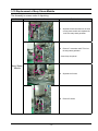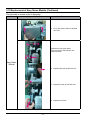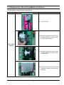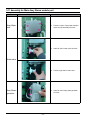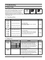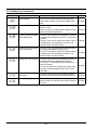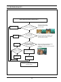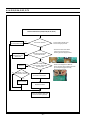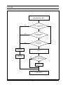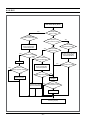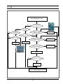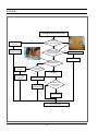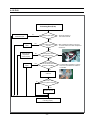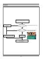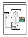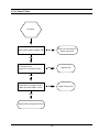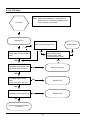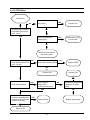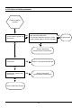
1
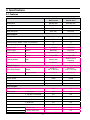
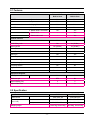
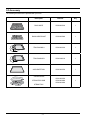
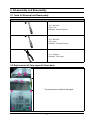
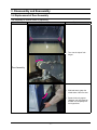
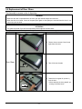
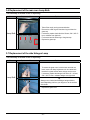
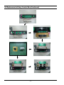
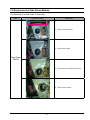
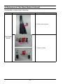
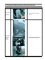
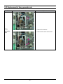
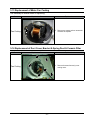
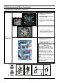
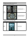
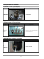
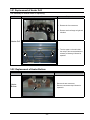
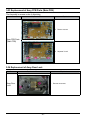
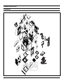
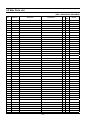
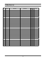
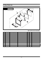
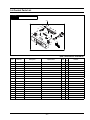
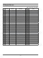
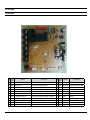
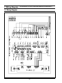
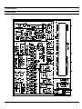
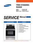
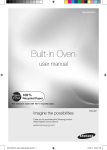
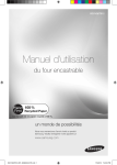
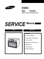
OVEN
BASIC:
BQ1Q4T090
MODEL:
BQ1VQ6T012
MODEL CODE : BQ1VQ6T012/XEF
SERVICE
OVEN
Manual
CONTENTS
1. Precaution
2. Product Specification
3. Disassembly and Reassembly
4. Troubleshooting
5. Exploded Views and Parts List
6. PCB Diagrams
7. Wiring Diagrams
8. Schematic Diagrams
Contents
1. Precaution. . . . . . . . . . . . . . . . . . . . . . . . . . . . . . . . . . . . . . . . . . . . . . . . . . . . . . . . . . . . . . . . . . . . . . . . . . . . . . 1
1-1 Safety precautions. . . . . . . . . . . . . . . . . . . . . . . . . . . . . . . . . . . . . . . . . . . . . . . . . . . . . . . . . . . . . . . . . . . . 1
2. Specifications . . . . . . . . . . . . . . . . . . . . . . . . . . . . . . . . . . . . . . . . . . . . . . . . . . . . . . . . . . . . . . . . . . . . . . . . . . .
2-1 Features. . . . . . . . . . . . . . . . . . . . . . . . . . . . . . . . . . . . . . . . . . . . . . . . . . . . . . . . . . . . . . . . . . . . . . . . . . . .
2-2 Specification. . . . . . . . . . . . . . . . . . . . . . . . . . . . . . . . . . . . . . . . . . . . . . . . . . . . . . . . . . . . . . . . . . . . . . . . .
2-3 Accessory. . . . . . . . . . . . . . . . . . . . . . . . . . . . . . . . . . . . . . . . . . . . . . . . . . . . . . . . . . . . . . . . . . . . . . . . . . .
2
2
3
4
3. Disassembly and Reassembly . . . . . . . . . . . . . . . . . . . . . . . . . . . . . . . . . . . . . . . . . . . . . . . . . . . . . . . . . . . . . . 5
3-1 Tools for Removal and Reassembly. . . . . . . . . . . . . . . . . . . . . . . . . . . . . . . . . . . . . . . . . . . . . . . . . . . . . . . 5
3-2 Replacement of Case upper & Cover back. . . . . . . . . . . . . . . . . . . . . . . . . . . . . . . . . . . . . . . . . . . . . . . . . 5
3-3 Replacement the Tube. . . . . . . . . . . . . . . . . . . . . . . . . . . . . . . . . . . . . . . . . . . . . . . . . . . . . . . . . . . . . . . . . 6
3-4 Replacement of Door Assembly. . . . . . . . . . . . . . . . . . . . . . . . . . . . . . . . . . . . . . . . . . . . . . . . . . . . . . . . . . 7
3-5 Replacement of Door Glass. . . . . . . . . . . . . . . . . . . . . . . . . . . . . . . . . . . . . . . . . . . . . . . . . . . . . . . . . . . . . 8
3-6 Replacement of the rear oven Lamp Bulb. . . . . . . . . . . . . . . . . . . . . . . . . . . . . . . . . . . . . . . . . . . . . . . . . 10
3-7 Replacement of the side Halogen Lamp . . . . . . . . . . . . . . . . . . . . . . . . . . . . . . . . . . . . . . . . . . . . . . . . . . 10
3-8 Replacement of Assy Control Box. . . . . . . . . . . . . . . . . . . . . . . . . . . . . . . . . . . . . . . . . . . . . . . . . . . . . . . 11
3-9 Replacement of Tube Steam Module. . . . . . . . . . . . . . . . . . . . . . . . . . . . . . . . . . . . . . . . . . . . . . . . . . . . . 13
3-10 Replacement of Assy Steam Module. . . . . . . . . . . . . . . . . . . . . . . . . . . . . . . . . . . . . . . . . . . . . . . . . . . . 15
3-11 Assembly for Main Assy Steam module part . . . . . . . . . . . . . . . . . . . . . . . . . . . . . . . . . . . . . . . . . . . . . . 18
3-12 Replacement of Assy generator sub . . . . . . . . . . . . . . . . . . . . . . . . . . . . . . . . . . . . . . . . . . . . . . . . . . . . 20
3-13 Replacement of Motor Fan Cooling. . . . . . . . . . . . . . . . . . . . . . . . . . . . . . . . . . . . . . . . . . . . . . . . . . . . . 21
3-14 Replacement of Duct Cover, Bracket & Spring Duct & Ceramic Filter. . . . . . . . . . . . . . . . . . . . . . . . . . . 21
3-15 Replacement of Motor Convection. . . . . . . . . . . . . . . . . . . . . . . . . . . . . . . . . . . . . . . . . . . . . . . . . . . . . . 22
3-16 Replacement of Heater Convection twin . . . . . . . . . . . . . . . . . . . . . . . . . . . . . . . . . . . . . . . . . . . . . . . . . 23
3-17 Replacement of Assy Partition S/W . . . . . . . . . . . . . . . . . . . . . . . . . . . . . . . . . . . . . . . . . . . . . . . . . . . . 23
3-18 Replacement of Thermostat . . . . . . . . . . . . . . . . . . . . . . . . . . . . . . . . . . . . . . . . . . . . . . . . . . . . . . . . . . 24
3-19 Replacement of Terminal Block. . . . . . . . . . . . . . . . . . . . . . . . . . . . . . . . . . . . . . . . . . . . . . . . . . . . . . . . 24
3-20 Replacement of Sensor Thermistor . . . . . . . . . . . . . . . . . . . . . . . . . . . . . . . . . . . . . . . . . . . . . . . . . . . . 24
3-21 Replacement of Heater Grill. . . . . . . . . . . . . . . . . . . . . . . . . . . . . . . . . . . . . . . . . . . . . . . . . . . . . . . . . . . 25
3-22 Replacement of Heater Bottom. . . . . . . . . . . . . . . . . . . . . . . . . . . . . . . . . . . . . . . . . . . . . . . . . . . . . . . . 25
3-23 Replacement of Assy PCB Parts (Main PCB) . . . . . . . . . . . . . . . . . . . . . . . . . . . . . . . . . . . . . . . . . . . . . 26
3-24 Replacement of Assy-Door Lock. . . . . . . . . . . . . . . . . . . . . . . . . . . . . . . . . . . . . . . . . . . . . . . . . . . . . . . 26
4. Troubleshooting. . . . . . . . . . . . . . . . . . . . . . . . . . . . . . . . . . . . . . . . . . . . . . . . . . . . . . . . . . . . . . . . . . . . . . . . . 27
4-1 Failure Codes. . . . . . . . . . . . . . . . . . . . . . . . . . . . . . . . . . . . . . . . . . . . . . . . . . . . . . . . . . . . . . . . . . . . . . . 27
5. Exploded Views and Parts List . . . . . . . . . . . . . . . . . . . . . . . . . . . . . . . . . . . . . . . . . . . . . . . . . . . . . . . . . . . . .
5-1 Exploded Views . . . . . . . . . . . . . . . . . . . . . . . . . . . . . . . . . . . . . . . . . . . . . . . . . . . . . . . . . . . . . . . . . . . . .
5-2 Main Parts List. . . . . . . . . . . . . . . . . . . . . . . . . . . . . . . . . . . . . . . . . . . . . . . . . . . . . . . . . . . . . . . . . . . . . .
5-2 Main Parts List. . . . . . . . . . . . . . . . . . . . . . . . . . . . . . . . . . . . . . . . . . . . . . . . . . . . . . . . . . . . . . . . . . . . . .
5-3 Door Parts List. . . . . . . . . . . . . . . . . . . . . . . . . . . . . . . . . . . . . . . . . . . . . . . . . . . . . . . . . . . . . . . . . . . . . .
5-4 Control Parts List. . . . . . . . . . . . . . . . . . . . . . . . . . . . . . . . . . . . . . . . . . . . . . . . . . . . . . . . . . . . . . . . . . . .
5-5 Standard Parts List. . . . . . . . . . . . . . . . . . . . . . . . . . . . . . . . . . . . . . . . . . . . . . . . . . . . . . . . . . . . . . . . . . .
43
43
44
45
46
47
48
6. PCB Diagram. . . . . . . . . . . . . . . . . . . . . . . . . . . . . . . . . . . . . . . . . . . . . . . . . . . . . . . . . . . . . . . . . . . . . . . . . . 49
6-1 PCB Diagram . . . . . . . . . . . . . . . . . . . . . . . . . . . . . . . . . . . . . . . . . . . . . . . . . . . . . . . . . . . . . . . . . . . . . . 49
7. Wiring Diagram. . . . . . . . . . . . . . . . . . . . . . . . . . . . . . . . . . . . . . . . . . . . . . . . . . . . . . . . . . . . . . . . . . . . . . . . . 50
7-1 Wiring Diagram . . . . . . . . . . . . . . . . . . . . . . . . . . . . . . . . . . . . . . . . . . . . . . . . . . . . . . . . . . . . . . . . . . . . . 50
8. Schematic Diagram. . . . . . . . . . . . . . . . . . . . . . . . . . . . . . . . . . . . . . . . . . . . . . . . . . . . . . . . . . . . . . . . . . . . . . 51
8-1 Schematic Diagram . . . . . . . . . . . . . . . . . . . . . . . . . . . . . . . . . . . . . . . . . . . . . . . . . . . . . . . . . . . . . . . . . . 51
1. Precaution
Follow these special safety precautions.
1-1 Safety precautions (
)
10. Always connect a test instrument’s ground lead to
the instrument chassis ground before connecting
the positive lead; always remove the instrument’s
ground lead last.
1. All repairs should be done in accordance with the
procedures described in this manual. This product
complies with Federal Performance Standard 21
CFR Subchapter J(DHHS).
2. Check all grounds.
3. Do not power the OVEN from a “2 - prong” AC cord.
Be sure that all of the built - in protective devices are
replaced. Restore any missing protective shields.
4. When reinstalling the chassis and its assemblies,
be sure to restore all protective devices including
nonmetallic control knobs and compartment covers.
5. Make sure that there are no cabinet openings
through which people --particularly children --might
insert objects and contact dangerous voltages.
11. Components that are critical for safety are indicated in the circuit diagram by shading,
or
.
12. Use replacement components that have the same
ratings, especially for flame resistance and dielectric strength specifications. A replacement part
that does not have the same safety characteristics
as the original might create shock, fire or other
hazards.
NOTE: Connect the oven to a 25 A.
When connecting the oven to a 16 A,
make sure that circuit breaker can operate.
6. Service technicians should remove their watches
while repairing an OVEN.
7. Design Alteration Warning:
Use exact replacement parts only, i.e., only those
that are specified in the drawings and parts lists of
this manual. Never alter or add to the mechanical or
electrical design of the OVEN. Any design changes
or additions will void the manufacturer’s warranty.
Always unplug the unit’s AC power cord from the
AC power source before attempting to remove or
reinstall any component or assembly.
13. Never touch any circuit wiring with your hand nor
with uninsulated tool during operation.
14. For your safety, wear gloves on your hands.
15. Remove the all water from water-tank and Steam
generator, before repairing the oven set.
8. Never defeat any of the B+ voltage interlocks. Do
not apply AC power to the unit (or any of its assemblies) unless all solid-state heat sinks are correctly
installed.
9. Some semiconductor (“solid state”) devices are
easily damaged by static electricity. Such components are called Electrostatically Sensitive Devices
(ESDs). Examples include integrated circuits and
field-effect transistors. Immediately before handling
any semiconductor components or assemblies,
drain the electrostatic charge from your body by
touching a known earth ground.
-1-
2. Specifications
2-1 Features
BASIC MODEL
Built In Oven
NEW MODEL
Built In Oven
Model Name
BQ1Q4T090
BQ1VQ6T012
Model Type Install
Single Built-in
Single Built-in
GEO
GEO
Dual cook
Dual cook
Pyro Lytic Coating
Pyro Lytic Coating
STSS
STSS
Q
Q
Door Opening
Drop Down
Drop Down
Interior Lamp
1(Halogen)
2(Halogen)
Back/Side
Back/Side
Tact Button & Dial
Tact & Touch & Dial
Display
2 Layer LED
2 Layer LED
Oven
Steam & Self
Steam & Self &
Descaling
Heater
Drop Down
Fixed
- Single
40~300 °C
300 °C: Grill only
40~270 °C
270 °C: Grill only
170~250 °C
170~250 °C
1600W/1100W
1600W/1100W
1100W
1100W
1200W/1200W
1200W/1200W
A/A/A
A/A/A
11
15
1. Convection
Yes
Yes
2. Top heat + convection
Yes
Yes
3. Conventional
Yes
Yes
4. Large Grill
Yes
Yes
5. Small Grill
Yes
Yes
6. Bottom + convection
Yes
Yes
7. Steam cook
-
Yes
6. Steam assist cook
-
Yes
Design
Main sales point
Oven Features
Cavity Interior
Oven Colors
Oven Doors (D: double, T: triple, Q: quadruple)
Interior Lights
position
Control Method(Oven)
Cleaning Method
Electric Features
Oven Temp Ranges
- Upper or Lower
Grill Heater (In/Out)
Bottom Heater
Convection Heater (Upper/Lower)
Energy Class
Oven Function
Number of Functions
Single Mode
-2-
2-1 Features
BASIC MODEL
Built In Oven
NEW MODEL
Built In Oven
1. Convection
Yes
Yes
2. Top heat + convection
Yes
Yes
3. Large grill
Yes
Yes
1. Convection
Yes
Yes
2. Bottom heat + convection
Yes
Yes
3. Steam cook
-
Yes
4. Steam assist cook
-
Yes
Clock
Yes
Yes
Child Safety Lock
Yes
Yes (Hidden)
Yes (Hidden)
Yes (Hidden)
Count Timer
Yes
Yes
Cook Time
Yes
Yes
End Time
Yes
Yes
Oven Temp
Yes
Yes
Steam Cleaning
Yes
Yes
Self Cleaning
Yes
Yes
Language Option
No
No
Light On/Off
Yes
Yes
Smart buzzer
Smart buzzer
No
No
YES
No
Square Baking Tray
2
2
Square Wire Rack
1
2
UPPER Mode
LOWER Mode
Control Features
Sound On/Off
Sound
Equipment Supplied
Multi spit
Barbecue spit
2-2 Specification
Specifications
BASIC
NEWMODEL
230V 50Hz, AC
230V 50Hz, AC
Outside
595 x 595 x 566mm
595 x 595 x 566mm
Cavity
440 x 365 x 405mm
440 x 365 x 405mm
Net 47Kg, Gross 52Kg
Net 49Kg, Gross 55Kg
Power source
Dimension
(W x H x D)
Shipping weight
-3-
2-3 Accessory
The following accessories are provided with your oven.
Description
Code No.
Q’ty
Rack-wire
DG59-00001A
1
RACK-WIRE ROAST
DG59-00004A
1
tray-Baking a
DG63-00012A
1
tray-Baking B
DG63-00011A
1
Assy-partition
DG97-00015A
1
DG01-00010A
DG63-00246A
DG63-00242A
1
Front
Front
STEAM-glass
STEAM-tray sub
STEAM-tray
-4-
3. Disassembly and Reassembly
3-1 Tools for Removal and Reassembly
Tool
1. Tool : Nut Driver
2. Type : 7mm
3. Remarks : Heater bracket Nut
1. Tool : Nut Driver
2. Type : 9mm
3. Remarks : Convection Fan Nut
1. Tool : Longnose
2. Remarks : Tube Clamp
3-2 Replacement of Case upper & Cover back
* You must remove it before the repair
-5-
3. Disassembly and Reassembly
3-3 Replacement the Tube
The Assembly is reverse order of disjointing.
Parts
Explaination Photo
Explaination
1. Prepare long-nose to remove
the Tube clamp.
2. Grab the Tube clamp with longnose.
Tube
3. remove the Tube clamp.
4. remove the Tube.
-6-
3. Disassembly and Reassembly
3-4 Replacement of Door Assembly
The Assembly is reverse order of disjointing.
Parts
Explaination Photo
Explaination
1. Turn over the clips of both
hinges.
Door Assembly
2. With both hands, grasp the
middle sides of the oven door.
3. Rotate the door by approx.
70degree until the hinges can
be taken out completely from
the hinges holes.
-7-
3-5 Replacement of Door Glass
The Assembly is reverse order of disjointing.
WARNING
Whenever the door is separated from the oven, the clips should always be turned over.
When the door is mounted, if some of the parts (Door glass or other parts) are removed from the door, it can
cause injury due to sheet.
ATTENTION
The glass may break if you use force especially on the edges of the front sheet.
Parts
Explaination Photo
Explaination
1. Remove the two screws of the left and
right sides of the door.
Door Glass
2. Take off the door bracket.
3. Detach the inner glass #1 (number 1)
from the door.
*W
hen assembly the inner glass#1, put
printing to direction below.
Glass #1
Printing
-8-
3-5 Replacement of Door Glass (Continued)
The Assembly is reverse order of disjointing.
Parts
Explaination Photo
Explaination
Glass #2
4. Detach the inner glass #2 and springbrackets from the door.
Door Glass
Door Bracket
Holder Glass
Rubber
Glass #1
Glass #2
Glass #3
Glass #4
-9-
3-6 Replacement of the rear oven Lamp Bulb
The Assembly is reverse order of disjointing.
Parts
Explaination Photo
Explaination
Lamp Bulb
Glass cap
Sheet ring
Metal ring
Lamp
1. Take off the cap by turning counterclockwise.
2. Remove the metal ring and the sheet ring and clean the
glass cap.
3. If necessary, replace the bulb with a 25 watt, 230 V, 300 °C
heat - resistant oven light bulb.
4. Fit the metal and the sheet ring to the glass cap.
5. Replace the glass cap.
3-7 Replacement of the side Halogen Lamp
The Assembly is reverse order of disjointing.
Parts
Lamp Bulb
Explaination Photo
Explaination
1. To remove the glass cover, hold the lower end with one
hand, insert a flat sharp implement such as a table knife
between the glass and the frame and pop out the cover.
2. If necessary, replace the halogen bulb with a 25 ~ 40 watt,
230 V, 300 °C heat - resistant halogen oven light bulb.
Tip
Always use a cloth when handling a halogen bulb to
avoid depositing oils from your fingers on to the surface
of the bulb.
3. Replace the glass cover.
- 10 -
3-8 Replacement of Assy Control Box
The Assembly is reverse order of disjointing.
Parts
Explaination Photo
Assy Knob Dial Assy Display
Encoder Parts
Buzzer
Assy Knob Dial
Select Parts
Assy Inlet
Door Lock
Assy PCB Parts
(Main PCB)
Pump Motor
Motor Fan Cooling
Explaination Photo
Explaination
1. Remove one connector from the main
pcb.
Assy
Control Box
2. Remove two Tubes and one connector at
assy inlet.
3. Remove 3 screws at both sides and top
inside of assy control box, lift up assy
control box and pull forward to separate.
- 11 -
3-8 Replacement of Assy Control Box (Continued)
Remove 2 screws.
Remove 11 screws.
Remove one connector.
Remove 4 screws.
- 12 -
3-9 Replacement of Tube Steam Module
The Assembly is reverse order of disjointing.
Parts
Explaination Photo
Explaination
1. Remove the control-box.
2. Remove the 3 tubes.
Tube Steam
Module
3. Remove the 2 connectors and 4 hook.
4. Remove the 4 screws.
- 13 -
3-9 Replacement of Tube Steam Module (Continued)
The Assembly is reverse order of disjointing.
Parts
Explaination Photo
Explaination
5. Remove the Pump Motor.
Tube Steam
Module
6. Remove 2 rubbers.
- 14 -
3-10 Replacement of Assy Steam Module
The Assembly is reverse order of disjointing.
Parts
Explaination Photo
Explaination
1. Seperate the wire-harness from the hook
on assy steam module and separate the
1 tube from assy steam generator.
2. Remove 7 connectors and 2 TCO from
the assy steam generator.
* Lower Lamp is optional.
Assy Steam
Module
3. Seperate the 2 tubes.
4. Remove 5 screws.
- 15 -
3-10 Replacement of Assy Steam Module (Continued)
The Assembly is reverse order of disjointing.
Parts
Explaination Photo
Explaination
5. Lift up assy steam module to seperate
from oven.
Seperate the cover upper steam.
There are totally 4 hook that each has
different direction.
Assy Steam
Module
6. Seperate right and up side hook first.
7. Seperate left and up side hook also.
8. Seperate last 2 hook.
- 16 -
3-10 Replacement of Assy Steam Module (Continued)
The Assembly is reverse order of disjointing.
Parts
Explaination Photo
Explaination
9. Remove 5 tubes.
10. Seperate the right side hook by using a
flat head screwdriver. And then remove
the assy steam generator.
Assy Steam
Module
11. Seperate the right side hook by using a
flat head screwdriver. And then remove
the water valve.
12. Seperate the 4 hook by using a flat head
screwdriver. And then remove the assy
water tank.
- 17 -
3-11 Assembly for Main Assy Steam module part
Parts
Explaination Photo
Explaination
Assy Water
tank
1. Press the 4 point of assy water tank and
check the right assembly with hook.
1. Insert left side of water valve into hook.
Water valve
2. Press the right side of water valve.
Assy Steam
1. Insert left side of assy steam generator
into hook.
generator
- 18 -
3-11 Assembly for Main Assy Steam module part (Continued)
Parts
Explaination Photo
Explaination
Assy Steam
2. Press the right side of assy steam
generator.
generator
Connectors
and Assy
steam
module
1. Check the right position between assy
steam module hole and connector.
- 19 -
3-12 Replacement of Assy generator sub
Parts
Explaination Photo
Explaination
Assy
generator
sub
1. Remove 2 connectors.
2. Remove the 2 tubes and 2 screws.
- 20 -
3-13 Replacement of Motor Fan Cooling
The Assembly is reverse order of disjointing.
Parts
Explaination Photo
Explaination
1. Remove two screws and turn toward the
clockwise to separate.
Fan Cooling
3-14 Replacement of Duct Cover, Bracket & Spring Duct & Ceramic Filter
Parts
Explaination Photo
Explaination
1. Remove 6 screws from ass’y cover
cooling motor.
Fan Cooling
- 21 -
3-15 Replacement of Motor Convection
The Assembly is reverse order of disjointing.
Parts
Explaination Photo
Explaination
1. Seperate the 1 tube from the
adiabatic rear.
* Be sure to connect tube again
when assembly.
2. Remove 5 screws at the back
inside cavity to separate the cover
casing.
3. Turn flange nut to the left to
release and separate spacer fan
convection and fan convection.
Motor
Convection
4. Remove two connector from
convection motor
5. Remove turn toward the counterclockwise to separate.
Reference
Convection fan is turn in the
opposite direction each other for
improvement cook performance.
Upper fan is turn in counterclockwise direction, Lower fan
is fan turn in clockwise direction
therefor convection fan direction
and netflange are opposited each
other.
Convection fan is indicated
(U),(L) and netflange is different
the head shape.
Upper
Upper
Lower
Main Blade
Motor
Convection
E-ring
Lower
Cavity
Nut-Hexagon cap
Nut-Hexagon cap
Fan-Convection
- 22 -
3-16 Replacement of Heater Convection twin
The Assembly is reverse order of disjointing.
Parts
Explaination Photo
Explaination
1. Remove the two connectors.
2. Remove two screws securing heater
convection twin at the rear.
Heater
Convection
Twin
3. Pull the securing bracket at the left
forward, and pull it toward the left to
separate heater convection twin.
3-17 Replacement of Assy Partition S/W
Parts
Explaination Photo
Explaination
Partition
S/W
1. Remove a connector.
2. Remove two screws.
- 23 -
3-18 Replacement of Thermostat
The Assembly is reverse order of disjointing.
Parts
Explaination Photo
Explaination
Thermostat
1. Unfold one point.
3-19 Replacement of Terminal Block
Parts
Explaination Photo
Explaination
Terminal
Block
1. Remove two wires from terminal block..
2. Remove three screws.
3-20 Replacement of Sensor Thermistor
Parts
Explaination Photo
Explaination
Sensor
Thermistor
1. Remove one screws.
- 24 -
3-21 Replacement of Heater Grill
The Assembly is reverse order of disjointing.
Parts
Explaination Photo
Explaination
1. Remove the four connectors.
2. Remove each nut frange at right and
left sides.
Heater Grill
3. Turn the upper nut circular inside
the cavity to the counterclockwise to
release, pull heater girll forward to
separate.
3-22 Replacement of Heater Bottom
Parts
Explaination Photo
Explaination
1. Remove the two connectors.
2. Remove one screw and pull forward to
separate it.
Heater
Bottom
- 25 -
3-23 Replacement of Assy PCB Parts (Main PCB)
The Assembly is reverse order of disjointing.
Parts
Explaination Photo
Explaination
1. Remove a screw.
Assy PCB Parts
(Main PCB)
2. Seperate 3 hook.
3-24 Replacement of Assy-Door Lock
Parts
Explaination Photo
Explaination
Assy-Door
Lock
1. Remove two screws.
- 26 -
4. Troubleshooting
4-1 Failure Codes
There are a kind of error code and two kinds of warning
codes. Possible error codes during use can be checked
before service. Press [Stand by Mode + Current time
0:00] and [Function + Time] at the same time and
hold them for 5 seconds, error codes are displayed.
Press [Function] button, the latest 5 error codes can be
checked. But, if the oven turns off, the stored error codes are deleted. Press [Function + Time] button to return to
‘normal display mode’.
4-1-1 Temp Sensor Error
Error Code
Gerneral Function
Solution
Page
Cavity upper sensor open
Cavity lower sensor open
Cooling motor sensor open
Sensor Open Error
It occurs due to a defective sensor, misplaced
wires, a defective PCB.
29 Page
Sensor Short Error
It occurs due to a defective sensor, misplaced
wires, a defective PCB. It may occur when the
ambient temperature falls under -5°C.
30 Page
Steam generator sensor open
Cavity upper sensor short
Cavity lower sensor short
Cooling motor sensor short
Steam generator sensor short
4-1-2 Safety Error
Error Code
Gerneral Function
Overtime
Temp
Time
~ 100°C
16 hours
105°C ~ 240°C
8 hours
245°C ~
4 hours
Touch Button Short
Solution
Page
This error occurs when the oven works during
CUT-OFF TIME in the same mode and at the same
temperature without any operation of an user.
This error is to prevent a risk of fire and hazards in
case an user forgets to turn off the oven after use or
the oven automatically starts in an unusual way.
The oven can be used after off.
32 Page
This error occurs when a button is pressed and held
for over 10 seconds.
It may occur when water soaks through the inside
of the control panel or dust particles are stuck to
TOUCH PAD. In this case, remove DISPLAY PCB,
clean TOUCH PAD PCB or replace it.
31 Page
- 27 -
4-1-2 Safety Error (Continued)
Error Code
Gerneral Function
Solution
Page
Divider Missing
This error occurs when the divider sensing switch
senses that the divider is used at the inappropriate
mode.
33 Page
Preheating Time Out
This error occurs when the set preheating time, 30
minutes, is over.
It may occur due to a heater’s open, defects of relay
contact point and wiring defects.
35 Page
Excess of cooking compart- - This error occurs when the temperature of cooking
ment’s temperature
compartment maintains over 320°C for more than 5
minutes.
- This error occurs when a fire occurs inside cooking
compartment or the temperature cannot be controlled because of sensor’s failure.
38 Page
Excess of cooking compart- - This error occur immediately after the temperature
ment’s temperature
of cooking compartment reaches 350°C.
- This error occurs when a fire occurs inside cooking
compartment or the temperature cannot be controlled because of sensor’s failure.
38 Page
Cooling motor lock sensed
- This error occurs when the temperature sensor on
the Main PCB senses abnormal temperature.
- It occurs 30 ~ 60 minutes after the cooling motor
does not operate.
- It may occur when the cooling motor stops running
by power off during operation of the oven, then it
runs again.
34 Page
Exess of steam generator
temperature
- This error occurs when the temperature sensor in
the steam generator senses abnormal temperature.
36 Page
Water valve open sensed
- This error occurs when generator sensor can not
sense the water even though water valve is opened
for 30 sec.
28 Page
- 28 -
4-1-3 E-27,E-29, E-2b, E-71
Sensor Open Error (E-27, E-29, E-2b, E-71)
YES
Connect the sensor.
Is the sensor disconnected?
: Check if the sensor housing
is inserted into the connector
of the main PCB.
NO
Connect the
wire properly.
NO
Is the sensor wire
connected properly?
: Check if the sensor wire is damaged, if the
housing is loose and if the sensor and the
wire are properly connected.
YES
S/W Error
Does the voltage change
as the humidity, temperature
and weight change?
NO
NO
After Power -> On, does
the symptom continue?
The sensor is out of order.
YES
Replace the PCB.
Replace the sensor.
Perform the operation again and check if it
is working properly.
- 29 -
: Check if the voltage of the GND and sensor
changes using a digital multi-meter
by forcefully changing the humidity, temperature
and weight.
4-1-4 E-28, E-2A, E-2C, E-72
Sensor Short Error (E-28, E-2A, E-2C, E-72)
Remove the shorted part YES
of the temperature sensor.
Is the sensor shorted?
: Check if both terminals of the
sensor are slightly shorted.
NO
Remove any foreign
Substance from the
shorted part.
YES
Is the sensor terminal part
of the PCB shorted?
: Check if the sensor and related
parts such as the connector or
soldering parts are slightly shorted.
NO
S/W Error
YES
Does the voltage change
as the humidity, temperature
and weight cha
NO
NO
After Power > On, does
the symptom continue?
The sensor is out of order.
YES
Replace the PCB.
Replace the sensor.
Perform the operation again and
check if it is working properly.
- 30 -
: Check if the voltage of the GND and
sensor changes using a digital multi-meter
by forcefully changing the humidity,
temperature and weight.
4-1-5 -SE-
Key Short Error (- SE -)
YES
Is the key not recognized
at all?
NO
YES
Is the key recognized
intermittently?
NO
Is a specific key
not recognized?
YES
NO
The membrane
is defective.
Replace the
Control Panel.
S/W Error
NO
After Power > On,
does the symptom continue?
YES
Replace the PCB.
Perform the operation again and check if it
is working properly.
- 31 -
4-1-6 S-01
Over Time Error (S-01)
YES
Is it temperature
100°C in oven?
NO
Has it worked for
6 hours continuously?
Is it temperature
105°C~240°C in oven?
NO
Re-check the Cut-Off-Time
for the corresponding
internal temperature.
YES
Is it temperature
245°C in oven?
NO
Re-check the Cut-Off-Time
for the corresponding
internal temperature.
NO
Does same error arise?
YES
Has it worked for
8 hours continuously?
NO
YES
YES
Has it worked for
4 hours continuously?
S/W Error
YES
NO
After Power > On,
does the symptom continue?
YES
Re-check the Cut-Off-Time
for the corresponding
internal temperature.
Does same error arise?
Replace the PCB.
NO
Turn the oven off and
let it cool sufficiently.
NO
Does same error arise?
NO
YES
S/W Error
After Power > On,
does the symptom continue?
YES
Replace the PCB.
Perform the operation again and check if it
is working properly.
- 32 -
4-1-7 dE
Divider Missing Error (dE)
NO
NO
NO
Is it Upper,
Lower Mode?
YES
YES
Is divider inserted?
YES
Single Mode?
YES
Is the Divider detection
S/W out of order?
Is divider inserted?
YES
Is the Divider detection S/W
connected properly?
Remove the Divider.
NO
Connect correctly wire.
YES
Are the connections in the
Main PCB normal?
NO
YES
S/W Error
NO
Replace S/W
NO
YES
NO
Insert divider
Is the Cooking Mode
Twing?
After Power > On,
does the symptom continue?
YES
Replace the PCB.
Perform the operation again and check if it
is working properly.
- 33 -
Connect correctly.
4-1-8 E-0b
Cooling Motor Sensor Error (E-0b)
Is the temperature
sensor of the PCB open?
YES
An “E-2b” error
occurred.
NO
Insert the
temperature sensor.
Was there a shortcircuit in the temperature
sensor of the PCB?
YES
An “E-2C” error occurred.
NO
Repair the short circuit.
Is the temperature
of the PCB over 90°C?
YES
An “E-0b” error
occurred.
NO
NO
Is the Cooling Motor
rotating?
S/W Error
YES
Check the Motor
drive part.
The temperature
sensor is out of order.
NO
Replace the
temperature sensor.
After Power > On,
does the symptom
continue?
YES
Replace the PCB.
Perform the operation again and check if it
is working properly.
- 34 -
4-1-9 E-08
Preheating Error (E-08)
Check the heater
related drive part.
NO
Does the heater work?
: Check the voltages of
both heater terminals.
YES
Replace the
heater.
YES
Is the heater temperature
very low?
: After operating the heater for more then
10 minutes check if the heater temperature
remains low.
NO
Reconnect the
temperature
sensor properly.
NO
Is the temperature sensor
connected properly?
YES
Replace the
heater.
YES
Is the resistance
between the heater terminals
more then a few MΩ?
NO
S/W Error
NO
After Power > On,
does the symptom continue?
YES
Replace the PCB.
Perform the operation again and check if it
is working properly.
- 35 -
: A normal heater’s resistance is a few Ω.
A short circuit increases the resistance
to a few MΩ.
4-1-10 E-73
Steam generator temp Error (E-73)
Temp sensor
malfunction.
NO
Does the steam generator
temp sensor work?
: Check the Resistance of temp sensor
YES
NO
Is the PCB part shorted?
: Check short circuit in the PCB part
such as relay and sensor part.
YES
Replace the Assy steam generator.
Replace the PCB.
Perform the operation again and check if it
is working properly.
- 36 -
4-1-11 E-78
Water Over Supply Error (E-78)
Connect steam generator
water level connector.
YES
Is steam generator water
level connector disconnected?
NO
NO
Does Water Valve work?
Replace the Water Valve
: Check short circuit in the PCB part
such as relay and sensor part.
YES
S/W Error
NO
After Power > On,
does the symptom continue?
YES
Replace the PCB.
Perform the operation again and check if it
is working properly.
- 37 -
4-1-12 E-0A, E-09
Internal Oven
Temperature
Abnormal
“E-09,
E-24, E-0A” 가
표시된다 Error (E-0A, E-09)
An “E-09” error
occurred.
YES
Is the oven internal temperature
maintained over 320 degrees?
NO
An “E-24, E-0A” error
occurred.
YES
Has the oven internal temperature
reached over 350 degrees?
NO
Reconnect the
temperature
sensor properly.
NO
Is the temperature
NO sensor
connectivity normal?
YES
Off
TurnOven을
the oven
off하고
and let
it 충분히
cool sufficiently.
식힌다.
Check
and repair
히터
the구동부를
heater
점검
수리한다
drive
part if
necessary.
NO
Is the Heater
connectivity normal?
YES
S/W Error
NO
After Power > On,
does the symptom
continue?
YES
Replace the PCB.
Perform the operation again and check
if it is working properly
- 38 -
4-1-13 Power Failure
No Power
- Check terminal block voltage, 230V.
NO
Reset The circuit braker or
Check main power
YES
- TCO open Check
(main TCO, Convection TCO)
NO
Replace TCO
NO
Repair Faulty wiring
YES
- Check the input voltage of PCB
SMPS (input checkpoint : 230V )
YES
Replace PCB or display PCB check
- 39 -
4-1-14 TCO Open
Note : When oven is operating , if main power off,
power oven off, in temporary temperature rise,
TCO is possible will can open.
TCO Open
Replace TCO
Replace Motor
- Motor Terminal Voltage check
NO
NO
- Colling motor, Conveclion Motor
check
YES
YES
- PCB SMPS Input Voltage check
(input check point: 5V, 230V)
• Motor Connect wire Remove
- Motor Resistor check
(Cooling motor: 238Ω
Convection Motor: 218Ω)
YES
NO
Repair Faulty wiring
NO
Replace PCB
YES
Replace PCB
YES
- PCB SMPS output Voltage
check
(output check point: 5V, 12C)
YES
- PCB Relay contact short check
NO
Check wire short and operation
of a sensor
- 40 -
NO
4-1-15 PCB Failure
PCB Failure
- TCO Open?
NO
- Check the input voltage of
PCB SMPS (input checkpoint : 230V )
YES
Replace TCO
NO
YES
-C
heck Terminal block
voltage(230V).
YES
Repair Faulty wiring
or PCB check
NO
Reset the circuit braker or
check main power.
- Check the output voltage of NO
PCB SMPS (Output checkpoint : 5V/12V )
NO
- Check fuse protecting SMPS
Replace FUSE
YES
Replace PCB
Replace PCB
YES
- Do all relays operate?
YES
NO
- Check the operating base
voltage(5V) which is appropriate for each relay.
• After Lamp On
- Safety Relay
Contact point ON(12V)?
YES
YES
NO
- Check the operating Base
voltage(0V) of Safety
Relay.
YES
Replace Relay
NO
Replace PCB
- 41 -
Replace Safety Relay
4-1-16 Failure of heating elements
Failure of heating
elements
- Check heater’s terminal voltage (230V)
YES
NO
• After removing Heater Wire
- Check Heater resistance (Large G :32.8Ω,
Small G:48.6Ω, Bottom : 48.1Ω, Conv:44Ω)
YES
- Repair Faulty wiring
(Possible termial contact failure)
- TCO Open?
YES
Perform “TCO Open Check Process”
NO
- Check Relay Terminal Voltage (230V)
YES
- Repair Faulty wiring
(Possible termial contact failure)
NO
Perform ‘PCB Check Process’
- 42 -
NO
Replace heater
5. Exploded Views and Parts List
5-1 Exploded Views
B034
W002
H052
M258
M007
C003
M302
M260
H008
M261
C003
P284
H051
C195
B028 B048
M392
D120
H054
P186
H094
H050
M251
H106
P214
H125
M253
H107
M032
H111
M003
H111
M242
P329
M229
M017
M264
M300
M294
P282
M262
M236
M032
H451
M013
M370
M293
M015
M389
M250
M482
W006
G005
P282
M265
M277
H053
U013
M279
M248
M249
M224
H049
H048
T111
P280
H123
T112
H057
T030
U005
Z814
H048
H049
H058
U029
P229
H005
M241
P285
U028
P225
Z031
D205
- 43 -
5-2 Main Parts List
(SNA : SERVICE NOT AVAILABLE)
No.
Code No.
Description
Specification
Q’ty
SA/
SNA
Remark
M260
DG61-00056A
SUPPORT-MOTOR COOLING
PA66+GF15%,BT63BSS
1
SA
-
- 44 -
5-2 Main Parts List
No.
Code No.
Description
Specification
- 45 -
Q’ty
SA/
SNA
Remark
5-3 Door Parts List
D049
ASSY DOOR
D151
D113
D110
D049
P420
D109
P421
D105
V002
D015
V002
D106
D147
D019
(SNA : SERVICE NOT AVAILABLE)
No.
Code No.
Description
Specification
- 46 -
Q’ty SA/SNA
Remark
5-4 Control Parts List
C082
ASSY CONTROL-BOX
C082
C187
Y101
C185
C235
C188
C360
C009
C048
C154
C197
C236
C188
C190
C187
Y102
C352
C178
C001
C074
C360
(SNA : SERVICE NOT AVAILABLE)
No.
Code No.
Description
Specification
- 47 -
Q’ty
SA/
SNA
Remark
5-5 Standard Parts List
(SNA : SERVICE NOT AVAILABLE)
LEVEL
Code No.
Description
Specification
- 48 -
Q’ty
SA/
SNA
Remark
6. PCB Diagram
6-1 PCB Diagram
No.
Parts
Number
No.
Parts
Number
Part Name
Function and Rule
1
CN101
Display connector-1
A Terminal for Connecting with display module.
12
RY104
Upper heater Relay
A relay for Connecting with Upper heater
2
CN102
3
CN103
Display connector-2
A Terminal for Connecting with display module.
13
RY105
Lower heater Relay
A relay for Connecting with Lower heater
Temp sensor & divider switch connector
A Terminal for Connecting with divider and temp sensor.
14
RY106
Latch open Relay
Latch open control
4
CN104
Buzzer
A Terminal for Connecting with speaker.
15
RY107
Latch close Relay
Latch close control
5
CN105
Door Lock motor connector
A Terminal for Connecting with Door Lock motor.
16
RY108
Uppwe lamp Relay
Uppwe lamp control
6
CN106
Neutral , upper/lower lamp
A Terminal for Connecting with Neutral,upper/lower lamp.
17
RY109
Lower lamp Relay
Lower lamp control
7
CN107
Spit , Upper/lower fan , Cooling fan
A Terminal for Connecting with Spit , Upper/lower fan , Cooling fan.
18
RY111
Spit Relay
Spit Source
8
CN108
Door latch , Door sensing
A Terminal for Connecting with Door latch , Door sensing
19
RY112
Source Relay
Supply power for all relay
9
RY101
Large grill Relay
A relay for Connecting with Large grill heater
20
SSR101 Upper fan SSR
Upper fan control
10
RY102
Small grill Relay
A relay for Connecting with Small grill heater
21
SSR102 Lower fan SSR
Lower fan control
11
RY103
Bottom heater Relay
A relay for Connecting with Bottom heater
22
SSR103 Cooling fan SSR
Cooling fan control
Part Name
Function and Rule
- 49 -
7. Wiring Diagram
( This Document can not be used without Samsung’s authorization. )
7-1 Wiring Diagram
- 50 -
8. Schematic Diagram
8-1 Schematic Diagram
3
8
D104
MBRF5100
R11
470K
R105
8
Vcc
7
In
6 Thr
1
R04
100K
INT
+5V
R106
20K
D105
1N4007
R03
10K
D02
EM518
R01
470K
R104
47K
Isw
2 Ire
C02
1uF
Out
DIVIDER & TEMP SENSOR
-TWIN & PYROLYTIC
C03
10uF
2
+5V
DV-SW
AD_U
3
4
AD_L
5
6
C301
10uF
C302
10uF
+5V
R803
2K
R801
13K
3
2
R802
80.6K
1
STEAM-TEMP
STEAM TEMP
CN501
SMW250-04_WHT
2K
R09
470
PC01
TLP-181
1
R501
13K
R503
2K
2
R502
80.6K
5
TXD
8
SCL
7
SDA
6
WAKE-UP
9
TOGGLE
3
5
+
6
-
R406
2K
R408
4
5
2K
R407
6
7
LATCH-1
LATCH-2
LIVE-2
RY203
DU12D1-1P
DOOR-SW
+
D203
MM4148
RY204
DU12D1-1P
7
-
2
RY205
DU12D1-1P
RY207
T9AS1D22-12
RY208
G5T-1A-ASI-12VDC
1
RY210
G5T-1A-ASI-12VDC
3
+
5
W-H
OUT
2
WL
-
+
W-L
OUT
1
6
CN204
SMW250-03A_RED
WH
IC402
KIA358F
VCC=+6V,GND=DGND
-
7
RY211
G5T-1A-ASI-12VDC
TR204
KRC246
TR205
KRC246
3
RY215
G5T-1A-ASI-12VDC
4
TR217
KRC246
TR209
KRC246
RY212
G5T-1A-ASI-12VDC
2
RXD1
3
TXD1
6
RESET
CN701
SMW200-06P
C701
100nF
200K
R414
200K
200K
1
TR210
KRC246
TR211
KRC246
RY213
G5T-1A-ASI-12VDC
TR212
KRC246
SL
1
3
WH
4
WM
5
WL
6
7
WATER
LEVEL
TR213
KRC246
SSR201
AQG22212
C202
10uF
LATCH-CONTROL
TR201
KRC246
5
TR218
KRC246
SSR202
AQG22212
M
NEUTRAL
SSR203
AQG22212
P
TR220
KRC246
RXD1
X1
R702
330
+5V
36 EMU1
GRILL-SUB
R601
2K
Vcc 8
1 A0
95
96
9
10
89
14
63
67
68
41
19
22
62
18
11
33
34
39
40
L-BAND-2
2 A1
WP
7
3 A2
SCL
6
CLK
4 Vss
SDA
5
DATA
DATA
CLK
S-LEVEL
IC601
24C04
W-H
+5V
W-M
W-L
R201
2K
TR221
KRC246
+5V
+5V
+5V
+5V
R302
26.1K
R301
26.1K
R303
R306
470
VCC
STAND-BY
LATCH-CONTROL
IC301
KIA75S393F
10K
DV-SW
LATCH-1
VEE
R304
1.87K
UPPER-LP
C307
100nF
LATCH-2
SIDE-RACK
VCC
R307
W-PUMP
IC302
KIA75S358
10K
C303
10nF
R308
1K
VEE
R309
12.7K
R311
2K
C304
10nF
R310
30.1K
+5V
R312
26.1K
S-U
TEMP SENSOR
PYROLYTIC TWIN
+6V
R313
IC303
KIA75S358
10K
C305
10nF
R314
1K
VEE
R315
12.7K
R317
2K
C306
10nF
R316
30.1K
COOLING
+5V
1
2
PROBE
AD-IN-U
AD-IN-L
STEAM-TEMP
TEST-1
TEST-2
SOURCE
LOWER-FAN
UPPER-FAN
GRILL-MAIN
GRILL-SUB
BOT-HT
UPPER-HT
LOWER-HT
STEAM-HT
W-VALVE
OPTION
LATCH-OPEN
LATCH-CLOSE
UPPER-LP
LOWER-LP
W-PUMP
COOLING
SPIT
U-BAND-2
U-BAND-1
R318
100K
R319
3.01K
AD_U
3
D303
MM4148
MM4148
L-BAND-1
L-BAND-2
R324
2K
AD-IN-L
2K
D301
MM4148
D302
MM4148
U-BAND-1
U-BAND-2
R320
2K
R321
AD-IN-U
2K
TEMP SENSOR N/P SINGLE
R902
R901
5.1K
Changed by
MS_JEON
- 51 -
S-L
PCB-TEMP
D304
R325
AD_U
4
2K
Engineer
Date Changed
17 JAN, 2011
SAMSUNG ELECTRONICS
MS_JEON
PCB-TEMP
416, Maetan-3Dong, Yeongtong-Gu,
Suwon-Si, Gyeonggi-Do, KOREA 443-742
Drawn by
MS_JEON
C901
1uF
+5V
M
R322
100K
AD_L
S-L
+5V
+5V
R323
3.01K
N/P TWIN
+5V
VCC
UPPER-FAN
S-U
TEMP SENSOR
PYROLYTIC
+6V
LOWER-LP
SPIT
DOOR-SW
R305
100K
TR222
KRC246
AD_U
LOWER-FAN
23 TXD1
24 RXD1
35 EMU0
TXD1
12pF
C601
100nF
SOURCE
AD_L
TR219
KRC246
SCL
TOGGLE
L-BAND-1
TR202
KRC246
LATCH-CLOSE
P
7
SDA
X2
12pF
EEP ROM
GRILL-MAIN
TR216
KRA226
TR208
KRC246
LATCH-OPEN
C201
10nF
TXD
EMU0
D202
MM4148
+5V
65 NMI
42
43
77 SDA0
78 SCL0
80
WAKE-UP
XTL1
16.000MHz
C117
RY202
DU12D1-1P
STEAM-HT
R114
2K
RXD
OPTION
D201
MM4148
DVSS
DVSS1
DVSS2
AVSS
28 X2
30 X1
X2
OSCILLATOR
RY201
DU12D1-1P
LOWER-HT
3
M
IC105
7033P
C116
29
64
86
4
97
90
98
91
99
100
92
1
8
7
2
88
69
87
84
83
82
81
79
6
76
75
70
21
72
71
74
73
20
25
12
13
17
16
15
52
60
59
47
48
49
50
51
46
44
45
53
54
55
56
57
61
58
94
93
37
38
OVP
X1
W-VALVE
TR215
KRC246
D212
MM4148
P
CN202
SMW250-07A_RED
EMU0
1
CN402
SMW250-07_WHT
2
R412
4
R413
R701
2K
200K
+5V
R411
+5V
5
+5V
TR214
KRC246
DVCC
DVCC1
DVCC2
VREFH
AVCC
AM0
AM1
32 RESET
INT
R113
2K
C113
10uF
D215
MM4148
UPPER-HT
TR206
KRC246
TR207
KRC246
+5V
2
D213
MM4148
On board writing
RESET
R112
2K
D214
MM4148
1
C115
100nF
RESET
RELAY
CONTROL
D211
MM4148
1
3
ZD101
UZ5.1B
D210
MM4148
5
7
C111
470uF
C110
470uF
R111
1K
C106
100nF
7
RY214
G5T-1A-ASI-12VDC
TR203
KRC246
D209
MM4148
1
3
8
D205
MM4148
9
IC401
KIA358F
VCC=+6V,GND=DGND
S7
1
27
66
85
3
5
26
31
C112
100nF
R110
220
PC102
TLP-181
D204
MM4148
RY209
G5T-1A-ASI-12VDC
W-M
OUT
S8
S6
2
IC103
KIA78D05PI
6
+12V
D208
MM4148
IC402
KIA358F
VCC=+6V,GND=DGND
3
S5
R109
12K
+12V
SIDE-RACK
LATCH
MODULE
WM
6
D207
MM4148
2K
8
B
C107
2.2nF
+5V
+5V
2K
2K
R405
3
S-LEVEL
OUT
R410
2K
R409
2
IC401
KIA358F
VCC=+6V,GND=DGND
SL
2K
2K
1
LIVE
CN201
SMW250-09A_RED
RXD
SMW250-08_WHT
4
CN401
CN102
SMW250-09(WHT)
2
R404
R403
1
5
6
OVP
3
+5V
D
E
D206
MM4148
+12V +5V
4
IC102
TNY276P
+6V
5
4
RY206
DU12D1-1P
DISPLAY PCB
C105
10uF
R10
1K
4
1
STAND-BY
C05
1nF
R06
12K
PROBE
R402
5
TR102
KRC246
C
4
D102
UF4007
D101
1N4007
+5V
KRA226
TR01
3
MEAT PROBE
CN801
SMW250-03_WHT
CN301
SMW250-06(WHT)
R05
47
R12
10K
R02
10K
C01
4.7uF
PC101
TLP-181
1
3
4
C114
1nF
R401
2K
RC
R08
1K
Gnd
2K
+5V
R07
470K
CN203
SMW250-04_RED
R103
47K
C04
100nF
IC01
LM331N
R102
47K
R101
47K
IC02
78L05
OVP
LIVE-2
D01
EM518
BOT-HT
LIVE-2
INTERRUPT
A
C109
470uF
47K
9
NEUTRAL
C108
470uF
47K
2
TR101
KRA226
R115
C104
1nF
IC104
KIA7812API
C
CN302
SMW250-04_BLU
2
R108
150K
A
TH901
TTC05103K
1
C103
10uF
C102
10uF
10
R116
1
+12V
D103
MBRF5100
ST101
ST-ALCD
ZNR101
560V
TVR14561
R107
1.2M
C101
100nF
IC101
TMP91FW60FG
+5V
POWER SUPPLY
BD101
DF06S
3
RESET
L101
LF-2CTOP
4
PTC101
270M
LIVE
R&D CHK
PCB TEMP
Time Changed
09:00 AM
DOC CTRL CHK
MFG ENGR CHK
QA CHK
Size
TITLE
A2
24" OVEN_MD
REV
Drawing Number
Sheet 1
of 1
GSPN (Global Service Partner Network)
Contry
Web Site
North America
service.samsungportal.com
Latin America
latin.samsungportal.com
CIS
cis.samsungportal.com
Europe
europe.samsungportal.com
China
china.samsungportal.com
Asia
asia.samsungportal.com
Mideast & Africa
mea.samsungportal.com
This Service Manual is a property of Samsung Electronics Co.,Ltd.
Any unauthorized use of Manual can be punished under applicable
International and/or domestic law.
© Samsung Electronics Co., Ltd. April
2011 Printed in Korea