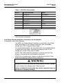
1
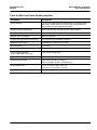
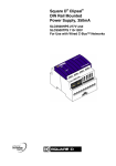
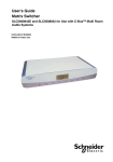
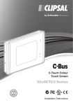
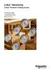
MRA Amplifiers Installation SLC560110R, SLC560125R, and SLC560125D for use with C-Bus™ Multi Room Audio Systems Instruction Bulletin Retain for future use. MRA Amplifiers Installation Instruction Bulletin 63249-420-339 A1 06/2010 HAZARD CATEGORIES AND SPECIAL SYMBOLS Read these instructions carefully and look at the equipment to become familiar with the device before trying to install, operate, service, or maintain it. The following special messages may appear throughout this bulletin or on the equipment to warn of potential hazards or to call attention to information that clarifies or simplifies a procedure. The addition of either symbol to a “Danger” or “Warning” safety label indicates that an electrical hazard exists which will result in personal injury if the instructions are not followed. This is the safety alert symbol. It is used to alert you to potential personal injury hazards. Obey all safety messages that follow this symbol to avoid possible injury or death. Danger indicates an immediately hazardous situation which, if not avoided, will result in death or serious injury. Warning indicates a potentially hazardous situation which, if not avoided, can result in death or serious injury. Caution indicates a potentially hazardous situation which, if not avoided, can result in minor or moderate injury. Caution, used without the safety alert symbol, indicates a potentially hazardous situation which, if not avoided, can result in property damage or improper operation. NOTE: Provides additional information to clarify or simplify a procedure. 2 © 2010 Schneider Electric. All Rights Reserved. 63249-420-339 A1 06/2010 MRA Amplifiers Installation Instruction Bulletin PLEASE NOTE Electrical equipment should be installed, operated, serviced, and maintained only by qualified personnel. This document is not intended as an instruction manual for untrained persons. No responsibility is assumed by Schneider Electric for any consequences arising out of the use of this manual. FCC CLASS B This device complies with Part 15 of the FCC Rules. Operation is subject to the following two conditions: (1) this device may not cause harmful interference, and (2) this device must accept any interference received, including interference that may cause undesired operation. This equipment has been tested and found to comply with the limits for a Class B digital device, pursuant to Part 15 of the FCC Rules. These limits are designed to provide reasonable protection against harmful interference in a residential installation. This equipment generates, uses, and can radiate radio frequency energy and, if not installed and used in accordance with the instructions, may cause harmful interference to radio communications. However, there is no guarantee that interference will not occur in a particular installation. If this equipment does cause harmful interference to radio or television reception, which can be determined by turning the equipment off and on, the user is encouraged to try to correct the interference by one or more of the following measures: Reorient or relocate the receiving antenna. Increase the separation between the equipment and receiver. Connect the equipment into an outlet on a circuit different from that to which the receiver is connected. Consult the dealer or an experienced radio/TV technician for help. Changes or modifications to this device that are not expressly approved by Schneider Electric could void the user's authority to operate this equipment. © 2010 Schneider Electric. All Rights Reserved. 3 MRA Amplifiers Installation Instruction Bulletin 63249-420-339 A1 06/2010 PRODUCT LABEL Refer to the warning label appearing on the product illustrated below. Refer to the "Notices" section at the beginning of this bulletin for definitions of the symbols appearing on the label. Carefully read and follow the safety precautions both on the equipment and contained in this bulletin before attempting to install or maintain electrical equipment. IMPORTANT SAFETY INSTRUCTIONS The appliance coupler shall remain readily operable once the product is installed. 1. Read these instructions. 2. Keep these instructions. 3. Heed all warnings. 4. Follow all instructions. 5. Do not use this apparatus near water. 6. Clean only with dry cloth. 7. Do not block any ventilation openings. Install in accordance with the manufacturer’s instructions. 8. Do not install near any heat sources such as radiators, heat registers, stoves, or other apparatus (including amplifiers) that product heat. 9. Do not defeat the purpose of the polarized or grounding-type plug. A polarized plug has two blades with one wider that the other. A grounding type plug has two blades and a third grounding prong. The wide blade or the third prong are provided for your safety. If the provided plug does not fit into your outlet, consult an electrician for replacement of the obsolete outlet. 10. Protect the power cord from being walked on or pinched particularly at plugs, convenience receptacles, and the point where the exit from the apparatus. 11. Only use the attachments/accessories specified by the manufacturer. 12. When a cart is used, use caution when moving the cart/apparatus combination to avoid injury from tip-over. 13. Unplug this apparatus during lightning storms or when unused for long periods of time. 14. Refer all servicing to qualified service personnel. Servicing is required when the apparatus has been damaged in any way such as power supply cord or plug is damaged, liquid has been spilled or objects have fallen into the apparatus, the apparatus has been exposed to rain or moisture, does not operate normally, or has been dropped. 4 © 2010 Schneider Electric. All Rights Reserved. 63249-420-339 A1 06/2010 MRA Amplifiers Installation Instruction Bulletin INTRODUCTION These installation instructions describe a stand alone Amplifier installation without a Matrix Switcher. This configuration includes connections to a power supply, loudspeakers, and a local stereo audio source. Connections to additional MRA Amplifiers can also be made. For installation instructions with a Matrix Switcher, refer to the Matrix Switcher Installation Bulletin. After the Remote Amplifier is installed, refer to the MRA Remote Amplifiers User Guide for operating instructions. MULTI ROOM AUDIO AMPLIFIERS A Multi Room Audio (MRA) Amplifier is part of a C-Bus enabled audio distribution system. C-Bus input units control the amplifier. Examples of C-Bus input units that control MRA amplifiers include Saturn™ and Neo™ wall switches, DLT™ switches, and Color Touchscreens. The Multi Room Audio (MRA) Amplifiers distribute audio to an assigned zone within a home or office as part of the MRA System. Three types of MRA amplifiers are shown in the figure below. A MRA layout may contain any combination of these amplifiers. A single amplifier is a valid configuration, and several amplifiers can be used or linked together on a C-Bus network. Figure 1: Catalog Numbers - MRA Amplifiers KEY: A. SLC560110R Low Power Remote Amplifier B. SLC560125R Remote Amplifier C. SLC560125D Desktop Amplifier All types of MRA amplifiers have connections for line level stereo inputs, speakers and C-Bus. When several amplifiers are connected together, a digital audio cable distributes the audio program from amplifier to amplifier. © 2010 Schneider Electric. All Rights Reserved. 5 MRA Amplifiers Installation Instruction Bulletin 63249-420-339 A1 06/2010 Figure 2: Desktop Amplifier (SLC560125D) Rear Panel KEY: A. Speaker outputs B. Digital audio input C. Zone output D. Local source E. Headphones F. C-Bus network G. Unit and C-Bus Indicators H. Digital audio output I. Optical input J. Infrared (IR) target K. External power Figure 3: Remote Amplifier (SLC560125R) Rear Panel KEY: A. Speaker outputs B. Digital audio input C. Zone out D. Local source E. Power indicator F. C-Bus network G. Unit and C-Bus Indicators H. Digital audio output I. Optical input J. Infrared (IR) target K. External power Figure 4: Low Power Remote Amplifier (SLC560110R) Rear Panel KEY: A. Speaker outputs B. Infrared (IR) target C. Digital input D. Local source E. Unit and C-Bus indicators F. C-Bus network G. (Factory) Programming H. External power 6 © 2010 Schneider Electric. All Rights Reserved. 63249-420-339 A1 06/2010 MRA Amplifiers Installation Instruction Bulletin FEATURES AND CAPABILITIES MRA amplifiers can be used in a standalone configuration without an MRA Matrix Switcher. Using a standalone MRA amplifier: A stereo input source from a CD player, PC sound card, MP3 player, or other line-level source is plugged in. Contact a C-Bus installer for a convenient stereo source input wall plate connection, if desired. Each amplifier in the installation is individually controlled using C-Bus. Controls include volume, tone, and muting the speakers. The Amplifier can be controlled through C-Bus input switches, a hand held remote control, and the Desktop Amplifier's manual front panel controls. The desktop model also has a power standby mode. Additional amplifiers can be added in other rooms. The program source is distributed from the first amplifier to other rooms. MRA is included in scenes. Timers and schedules are used. The user can plan for future expansion including multiple audio zones and multiple source selection using the MRA Matrix Switcher. © 2010 Schneider Electric. All Rights Reserved. 7 MRA Amplifiers Installation Instruction Bulletin 63249-420-339 A1 06/2010 SAFETY PRECAUTIONS This section contains important safety precautions that must be followed before attempting to install or maintain electrical equipment. Carefully read and follow the safety precautions below. HAZARD OF ELECTRIC SHOCK, EXPLOSION, OR ARC FLASH Apply appropriate personal protective equipment (PPE) and follow safe electrical work practices. See NFPA 70E. This equipment must be installed and serviced by qualified electrical personnel. Turn off all electrical power supplying this equipment before working on or inside the equipment. Always use a properly rated voltage sensing device to confirm that power is off. Replace all devices, doors, and covers before turning on power to this equipment. Failure to follow these instructions will result in death or serious injury. The amplifiers can produce sounds loud enough to cause permanent hearing loss. HAZARD OF PERMANENT HEARING LOSS Keep volume controls at low levels when selecting program sources or when connecting local audio sources to an MRA amplifier. Plug the headphones into the MRA amplifier before placing the ear pieces on your head or in ears. Do not allow children to use the MRA equipment without adequate supervision. Failure to follow these instructions will result in serious injury. 8 © 2010 Schneider Electric. All Rights Reserved. 63249-420-339 A1 06/2010 MRA Amplifiers Installation Instruction Bulletin The MRA units require adequate ventilation. HAZARD OF OVERHEATING Do not cover or block the vents on the matrix switcher, MRA amplifiers or power supplies. Provide a clear space around the equipment, at least 2 inches (50 mm) to the front and rear and 0.6 inches (15 mm) above. Failure to follow these instructions can result fire, overheating equipment, or serious injury. EQUIPMENT PLACEMENT When installing the amplifier and speakers, choose a location close to the audio input source and wall power outlet to reduce the amount of cable needed. Consider the proximity to the C-Bus input units that control the amplifier as well. For multiple amplifier installations, the amplifiers may be set up in either a centralized or distributed layout: Use a centralized layout for configurations with multiple Low Powered Amplifiers, especially if the Amplifiers are installed in a 19-inch equipment rack. Networking and digital audio cable runs are shorter, and speaker wire runs are longer in a centralized layout. Also, multiple power outlets are needed at one location. Use a distributed layout to install amplifiers in convenient locations in a home. For example, a remote amplifier could be installed in a space above a ceiling, and use concealed speakers. Networking and digital audio cable runs are longer, and speaker wire runs are shorter in a distributed layout. © 2010 Schneider Electric. All Rights Reserved. 9 MRA Amplifiers Installation Instruction Bulletin 63249-420-339 A1 06/2010 SELECTING A LOCATION Consider the following factors when selecting a location. Verify that adequate ventilation is available for cooling the Amplifier. Keep the Amplifier uncovered. The Amplifier is intended for indoor use only. Do not expose it to any liquid. A 120V power outlet is required for the Amplifier to plug into. Ensure at least 1.97in. (50mm) of free space is available at each side of the Remote (SLC560125R) and Desktop (SLC560125D) Amplifiers. Allow at least 0.59in. (15mm) of free space directly above the units for ventilation. NOTE: This does not apply to the Low Power Remote Amplifier (SLC560110R). Ensure and speaker wires do not present a tripping hazard. WIRING DIAGRAMS Wiring diagrams are provided for typical installations using one amplifier and multiple amplifiers. NOTE: Multiple amplifiers have one analog input source and a digital audio connection between the amplifiers. Follow these guidelines and precautions when making wiring connections. EQUIPMENT DAMAGE OR IMPROPER OPERATION Do not plug a C-Bus network cable into a Digital Audio socket. Connecting C-Bus cables to the Digital Audio sockets damage the amplifier. Speaker wiring is polarity sensitive. Use consistent speaker wiring practices to preserve polarity and optimal sound quality. Follow the speaker manufacturer's recommendations for connecting multiple speakers to an amplifier. Keep all cable runs as short as possible. Use high-quality cables appropriate for the application. Failure to follow these instructions can cause damage to the MRA system or poor quality sound 10 © 2010 Schneider Electric. All Rights Reserved. 63249-420-339 A1 06/2010 MRA Amplifiers Installation Instruction Bulletin Wiring Diagram-Standalone Amplifier The wiring diagram below shows the connections for one amplifier with a single pair of speakers. Figure 5: Typical Cable Connections - Single Amplifier/Standalone Audio Source KEY: A. MRA Amplifier B. Audio input (LOCAL IN) C. C-Bus network cable D. External power E. Power supply F. Wall power outlet G. Speakers Multiple Amplifiers in Standalone Configuration If more than one amplifier is connected to a standalone configuration, the digital audio feature of the amplifiers is used. Only one source input can be active for all connected amplifiers. Connecting multiple sources causes poor sound quality. Before connecting two or more Amplifiers: confirm each standalone MRA Amplifier has its own power supply and speakers. mark the digital audio cables so they are not confused with the C-Bus network cables. NOTE: Never plug C-Bus network cables into digital audio or LAN sockets, or vice versa. use an RJ45 Tee connector at the digital audio socket for Low Power Amplifiers that are connected to an upstream or a downstream Amplifier. confirm positive and negative speaker wires are wired correctly to ensure the best sound quality. install a ferrite filter on each digital audio cable. See the figure below for a typical installation. For other configurations refer to the Multi Room Audio Matrix Switcher Installation Instruction Bulletin. © 2010 Schneider Electric. All Rights Reserved. 11 MRA Amplifiers Installation Instruction Bulletin 63249-420-339 A1 06/2010 Figure 6: Typical Cable Connections - Two Amplifiers/Single Audio Source KEY: A. MRA Amplifier B. Audio input (LOCAL IN) C. C-Bus network cable D. ¹ Digital audio out ² Digital audio in E. Power supply F. Wall power outlet G. Speakers NOTE: All amplifiers in a standalone layout share a common stereo input that is connected to the first amplifier. The C-Bus input devices individually control each amplifier. 12 © 2010 Schneider Electric. All Rights Reserved. 63249-420-339 A1 06/2010 MRA Amplifiers Installation Instruction Bulletin CONNECTING THE SPEAKERS The MRA Remote and Desktop Amplifiers use spring-type connectors. The Low Power Remote Amplifier uses a screw-type connector. HAZARD OF IMPROPER AUDIO, C-BUS AND SPEAKER CONNECTIONS Connect all audio and C-Bus cables to the appropriate terminal location of each unit. Connect all speakers in phase. Follow the manufacturer's wiring instructions. Do not short the positive and negative speaker wires together. Do not make any connection between speakers connected to different amplifiers. Do not connect any speaker wires to ground. Failure to follow these instructions can result in equipment damage, improper operation, or poor sound quality. 1. Remove the power supply from the wall power outlet. NOTE: Unplugging the power supply causes the amplifier to return to its default values for volume and tone settings or to the settings programmed using C-Bus Toolkit. To restore power to the amplifiers, follow the instructions in the section - Powering On the Amplifiers. 2. Connect the loudspeakers to low-impedance, stranded speaker cable. NOTE: The impedance of the cables should not exceed 5% of the impedance of the speakers. As a general rule, the larger the diameter of the speaker cable's conductors, the lower the impedance. 3. Connect the other end of the speaker cable to the output terminals on the Amplifier. Observe the positive (+) and negative (-) markings on the Amplifier. Refer to the Amplifer Loudspeaker Connections image. NOTE: Consistently connect the cables to the speakers throughout the installation. If speaker wire polarity is incorrect, sound quality will be poor. © 2010 Schneider Electric. All Rights Reserved. 13 MRA Amplifiers Installation Instruction Bulletin 63249-420-339 A1 06/2010 In certain cases multiple speakers may be connected to each channel of the Amplifier. Contact your C-Bus Installer if you are unsure about cable connections or terminals. Figure 7: Amplifier Loud Speaker Connections 1. MRA Remote Amplifier A. Left speaker positive (+) and negative (-) B. Right speaker positive (+) and negative (-) 2. MRA Low Power Remote Amplifier C. Loudspeaker connection CONNECTION TO THE C-BUS NETWORK Each Amplifier has a connection to the C-Bus network. C-Bus wall switches control the volume, bass and treble settings for the amplifier through the network. C-Bus Toolkit configuration software is used to configure wall switches to control the Amplifiers. Both the MRA Remote and Desktop Amplifiers use RJ45 plugs for C-Bus connection. The MRA Low Power Remote Amplifier is terminated with a screw type connector. Refer to the C-Bus connection information below for connection information on MRA Remote and Desktop Amplifiers, then the MRA Low Power Remote Amplifier. 1. Rear Panel of MRA Desktop and Remote Amplifiers A. Local Source Inputs B. Headphones Connection C. C-Bus Network D. C-Bus and Unit Indicators 2. Rear Panel of MRA Low Power Remote Amplifier E. Local Source Input F. C-Bus Network G. C-Bus and Unit Indicators 14 Figure 8: Connections to the C-Bus Network © 2010 Schneider Electric. All Rights Reserved. 63249-420-339 A1 06/2010 MRA Amplifiers Installation Instruction Bulletin Desktop and Remote Amplifier's Connection to the Network Connection to the C-Bus Network The C-Bus network is connected to the MRA Remote and Desktop Amplifiers through two polarity sensitive RJ45 inputs located on the MRA Remote and Desktop Amplifiers. Connect the unit to the C-Bus network with Category 5 unshielded twisted pair C-Bus network cable, and a wired RJ45 plug. Refer to the "Wiring Connections Key Diagram" figure, and the "RJ45 Pin Connections" table for wiring and pin connection information. NOTE: To clearly distinguish C-Bus from other UTP Cat5 cables, it is recommended to use a different colored cable, or clearly label the C-Bus UTP Cat5 cable. NOTE: The Category 5 unshielded twisted pair C-Bus network cable and the wired RJ45 plug are provided by the installer. HAZARD OF ELECTRIC SHOCK, EXPLOSION, OR ARC FLASH Do not connect line voltage to any C-Bus terminal. Failure to follow this instruction can result in personal injury or equipment or property damage. Figure 9: Wiring Connections Key Diagram KEY: A. C-Bus positive (+): blue + orange B. C-Bus negative (-): blue/white + orange/white C. Remote OFF: brown + brown/white* D. Remote ON: green + green/white* © 2010 Schneider Electric. All Rights Reserved. 15 MRA Amplifiers Installation Instruction Bulletin 63249-420-339 A1 06/2010 Table 1: RJ45 Pin Connections RJ Pin C-Bus Connection Color 1 Remote ON* Green/White 2 Remote ON* Green 3 C-Bus Neg (-) Orange/White 4 C-Bus Pos (+) Blue 5 C-Bus Neg (-) Blue/White 6 C-Bus Pos (+) Orange 7 Remote OFF* Brown/White 8 Remote OFF* Brown *Not internally connected. Low Power Remote Amplifier's Connection to the Network Connection to the C-Bus Network The MRA Low Power Remote Amplifier is connected to the C-Bus network through a C-Bus network cable that uses unshielded twisted pair (UTP) Category 5 data cable. For optimal performance, use the connections recommended below for each end of the cable. Attach the bootlace terminals to the twisted pairs of the C-Bus network cable. NOTE: The C-Bus network connection is polarity sensitive. The polarity is marked on the unit beside the terminals. NOTE: Do not solder wires used to connect the unit to the C-Bus network through the terminal block connections. HAZARD OF ELECTRIC SHOCK, EXPLOSION, OR ARC FLASH Do not connect line voltage to any C-Bus terminal. Failure to follow this instruction can result in personal injury or equipment or property damage. 16 © 2010 Schneider Electric. All Rights Reserved. 63249-420-339 A1 06/2010 MRA Amplifiers Installation Instruction Bulletin Table 2: C-Bus Cable Conductor Assignments Terminal C-Bus Network Connection Cable Color Not connected Remote ON* Green-White Not connected Remote ON* Green C-Bus Neg (–) C-Bus Neg (–) Orange-White C-Bus Neg (–) C-Bus Neg (–) Blue-White C-Bus Pos (+) C-Bus Pos (+) Blue C-Bus Pos (+) C-Bus Pos (+) Orange Not connected Remote OFF* Brown-White Not connected Remote OFF* Brown *Not internally connected. CONNECTING A STEREO SOURCE For best audio quality, always use high quality audio cables and keep the cable lengths as short as possible. The MRA amplifiers use line level signals only. Connecting high-level speaker outputs from audio source equipment will result in poor sound quality. Examples of audio equipment you can connect include, CD and DVD players, PC sound cards (line output, not speaker outputs), and MP3 players that have a line output. Normally, the volume of the input source is not adjustable and the MRA amplifier controls the volume. Use C-Bus and the MRA amplifier to adjust tone settings as well. More than one MRA amplifier can be installed in a standalone configuration, but only one stereo input source can be used for all of the connected amplifiers. Connecting multiple sources will cause the sound quality to suffer. There are two possible connector types for audio cable attachment to the amplifier. Refer to the table below. Table 3: Local IN Connector Details Amplifier type LOCAL IN connector SLC560125D Desktop and SLC560125R Remote Left (L) RCA phono jack Right (R) RCA phono jack SLC560125R Low Power Remote 3.5 mm stereo jack Connect the stereo audio cable from the source equipment to the location shown in the figure below. © 2010 Schneider Electric. All Rights Reserved. 17 MRA Amplifiers Installation Instruction Bulletin 63249-420-339 A1 06/2010 Figure 10: MRA Amplifiers - Local IN Connections KEY: 1. Remote Amplifier (SLC560125R) and Desktop Amplifier (SLC560125D) A. LOCAL IN source connections using RCA plugs 2. Low Power Remote Amplifier (SLC560110R) B. LOCAL IN source connections using 3.5mm stereo plug Optical Input for Remote and Desktop Amplifiers Amplifier Type How to Use OPTICAL IN SLC560125R MRA Remote Amplifier OPTICAL IN can be used with a standalone MRA Remote Amplifier; however an OPTICAL IN and LOCAL IN source cannot be connected at the same time. Disconnect the LOCAL IN cables before connecting an OPTICAL IN source. SLC560125D MRA Desktop Amplifier Both an OPTICAL IN and LOCAL IN source can be connected through the MRA Desktop Amplifier; however the OPTICAL IN and LOCAL IN connections cannot be used at the same time. Use the source switch to toggle between these sources. NOTE: Optical input is not available for the Low Power Remote Amplifier (SLC560110R). 18 © 2010 Schneider Electric. All Rights Reserved. 63249-420-339 A1 06/2010 MRA Amplifiers Installation Instruction Bulletin SELECTING AN AMPLIFIER POWER SUPPLY Each Amplifier used in a standalone configuration requires a power supply connected to the Amplifier's external power socket. Use only the power supplies specified below. Do not substitute any other power supply. Catalog Number Description SLC5600P243750T MRA High Temperature Switch Mode Amplifier Power Supply: 24Vdc @ 3.75A. Required for all high temperature locations.* SLC5600P241250 Low Power Remote Amplifier Power Supply: 24Vdc @ 1.25A. Only suitable for the Low Power Remote Amplifier. *NOTE: Use the High Temperature Switch Mode Amplifier Power Supply for all amplifier types when installing in warm to hot locations. The High Temperature Power Supply includes a cable adapter for use with the Low Power Amplifier. NOTE:The Low Power Remote Amplifier Power supply can only be used with the Low Power Remote Amplifier. Connecting the Power Supply The High Temperature Power Supply connects to the Amplifier and power outlet through a power cord. When using the High Temperature Power Supply with the Low Power Amplifier, use the cable adapter provided with the power supply. The Low Power Remote Amplifier Power Supply is a plug pack design that plugs directly into a power outlet. For additional information, and specifications for each power supply, refer to the instruction bulletin provided with the Power Supply. 1. Plug the end of the power supply output cable into the External Power Connector on the back panel of the MRA Amplifier. Refer to the Amplifier External Power Connection figure. 2. Install ferrite filters (not provided) on the power supply cable between the power supply and MRA Amplifier. The filter halves latch when closed over the cable. 3. After the C-Bus cable, loudspeakers, and audio input are connected, connect the power supply to a power outlet. © 2010 Schneider Electric. All Rights Reserved. 19 MRA Amplifiers Installation Instruction Bulletin 63249-420-339 A1 06/2010 Figure 11: Amplifier External Power Connection 1. SLC560125R Remote Amplifier or SLC560125D Desktop Amplifier A. External Power Connector B. Infrared (IR) target connector* 2. SLC560110R Low Power Remote Amplifier C. External Power Connector D. Infrared (IR) target connector* E. Programming (factory use only) *NOTE: The IR Target connector is used with the Matrix Switcher. Refer to the C-Bus Multi Room Audio Matrix Switcher Installation Bulletin for IR Target applications. TESTING THE AMPLIFIERS For additional instructions, including how to power on the Amplifiers, refer to the MRA Amplifier User Guide. Follow these guidelines when testing the functionality of the installation. 20 Configure the C-Bus wall switches to control the volume, bass/treble, and muting before connecting an audio source. Refer to the wall switch instruction bulletins, and the C-Bus Toolkit Software Data Bulletin for information. Power off Amplifiers before connecting audio sources or network cables. Mute the speakers before connecting or disconnecting. Use an MP3 player or other equipment as an audio source. Do not Megger test the C-Bus network cable. © 2010 Schneider Electric. All Rights Reserved. 63249-420-339 A1 06/2010 MRA Amplifiers Installation Instruction Bulletin CARE AND CLEANING INSTRUCTIONS Follow the precautions below to properly clean and care for the unit. Clean regularly using a soft lint free cloth. Only use a mild, non-abrasive cleaner such as window cleaner lightly sprayed onto the lint free cloth to clean the unit. Ensure hands are dry and clean before operating the unit. Only use non-abrasive objects to operate the unit. Hard, sharp objects may cause damage. Leave the unit uncovered to allow adequate ventilation. Only use the unit indoors. Properly shade the unit so that it is not exposed to direct sunlight for extended periods. TROUBLESHOOTING Symptom Possible Explanation There is no sound after switching the Amplifier ON (sound worked previously). Confirm the volume is not set to minimum, or muted (on a Desktop Amplifier). After switching the Amplifier ON, the default volume, bass, or treble settings have changed. If a power failure occurs when the Amplifier is ON, the volume, bass, or treble settings are saved and become the new defaults. The Amplifier switches off when the volume is loud. The Amplifier switches OFF if insufficient current is available. This may occur if the Amplifier receives its power from a Matrix Switcher. Cannot hear any sound when using the optical input. Some digital audio formats, such as surround sound, are incompatible with the MRA System. © 2010 Schneider Electric. All Rights Reserved. 21 MRA Amplifiers Installation Instruction Bulletin 63249-420-339 A1 06/2010 STANDARDS The Amplifier complies with the following Standards: Table 4: U.S. and Canadian Product Safety Standards and U.S. FCC Regulations Standards/Regulations Title CSA C22.2 No. 205 Signal Equipment UL60065 Video and Similar Electronic Apparatus FCC Part 15 Class B Digital Device for Home or Office Use SPECIFICATIONS Table 5: MRA Desktop and Remote Amplifiers Parameter Description Supply voltage 27 V DC (powered by Matrix Switcher via digital audio connection) and/or 24 V DC @ 3.75 A (via external switch mode power supply) or 21 V AC @ 3.5 A (via external linear power supply) Nominal voltage requirements Draws 15–36 V DC @ 22 mA from the C-Bus network Power consumption 90 W maximum Network clock and burden Software selectable Analog input signal level (local inputs) 2.8 V peak-to-peak maximum (47 kOhm) Maximum power output 28 W RMS into 4 Ohm (0.514% THD) D/A conversion 16 bit PCM Frequency response 40 Hz–20 kHz (±1 dB) Total harmonic distortion (1 kHz, 20 W RMS into 4 Ohm) 0.36% (using analog input) Signal-to-noise ratio > 67 dB (peak, unweighted) Operating environment Temperature: Desktop Amp: 50–104°F (10–40°C) Remote Amp: 50–158°F (10–70°C) Relative humidity: 10–90%, noncondensing Overall Dimensions Desktop Amp: 8.45 in. (L) x 7.09 in. (W) x 2.81 in. (H) (21.46 cm [L] x 18 cm [W] x 7.14 cm [H]) Remote Amp: 8.33 in. (L) x 6.89 in. (W) x 2.78 in. (H) (21.16 cm [L] x 17.5 cm [W] x 7.06 cm [H]) Weight Desktop Amp: 3.91 lb (1.77 kg) Remote Amp: 4.39 lb (1.99 kg) 22 © 2010 Schneider Electric. All Rights Reserved. 63249-420-339 A1 06/2010 MRA Amplifiers Installation Instruction Bulletin Table 6: MRA Low Power Remote Amplifier Parameter Description Supply Voltage 27V DC when powered by the Matrix Switcher (via digital audio connection), and/or 24V DC @ 1.25A when using the external power supply or switch mode power supply Nominal voltage requirements Draws 15 to 36V DC @ 22mA from the C-Bus network Power consumption 30W maximum Network clock and burden Software selectable Analog input signal level (local inputs) 2.8 V peak-to-peak maximum (47 kOhm) Maximum power output 10 W RMS into 4 Ohm (0.514% THD) D/A conversion 16 bit PCM Frequency response 40 Hz - 20 kHz (±1 dB) Total harmonic distortion (1 kHz, 20W RMS into 4 Ohm) 0.36% (using analog input) Signal-to-noise ratio > 67 dB (peak, unweighted) Operating environment Temperature: 50-158°F (10-70°C) Relative humidity: 10-90%, noncondensing Overall Dimensions 6.32 in. (L) x 4.8 in. (W) x 1.6 in. (H) (15.8 cm [L] x 12 cm [W] x 4 cm [H]) Weight 1.33lb (0.60 kg) © 2010 Schneider Electric. All Rights Reserved. 23 MRA Amplifiers Installation Instruction Bulletin SUPPORT AND SERVICE Contact the Customer Information Center for technical support by phone at 1-888-778-2733 or e-mail at [email protected]. Contact your local Schneider Electric service representative or C-Bus™ system certified installer for repairs or service to your network. You may also find helpful information on our web site at www.Schneider-Electric.us. Schneider Electric, USA 320 Tech Park Drive, Suite 100 La Vergne, TN, 37086 1-888-778-2733 www.schneider-electric.us Schneider Electric and logo are trademarks or registered trademarks of Schneider Electric and/or its affiliates in the United States and/or other countries. Electrical equipment should be installed, operated, serviced, and maintained only by qualified personnel. No responsibility is assumed by Schneider Electric for any consequences arising out of the use of this material. © 2010 Schneider Electric. All Rights Reserved. 63249-420-339 A1 06/2010