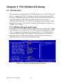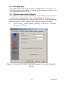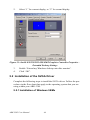
1
ARK-3382
Embedded Box Computer
User Manual
Copyright
The documentation and the software included with this product are copyrighted 2008 by Advantech Co., Ltd. All rights are reserved. Advantech
Co., Ltd. reserves the right to make improvements in the products
described in this manual at any time without notice. No part of this manual may be reproduced, copied, translated or transmitted in any form or
by any means without the prior written permission of Advantech Co., Ltd.
Information provided in this manual is intended to be accurate and reliable. However, Advantech Co., Ltd. assumes no responsibility for its use,
nor for any infringements of the rights of third parties, which may result
from its use.
Acknowledgements
Intel and Pentium are trademarks of Intel Corporation.
Microsoft Windows and MS-DOS are registered trademarks of
Microsoft Corp.
All other product names or trademarks are properties of their respective
owners.
Part No. 2006338213
Edition 3
Printed in Taiwan
August 2008
ARK-3382 User Manual
ii
Product Warranty (2 year)
Advantech warrants to you, the original purchaser, that each of its products will be free from defects in materials and workmanship for two year
from the date of purchase.
This warranty does not apply to any products which have been repaired or
altered by persons other than repair personnel authorized by Advantech,
or which have been subject to misuse, abuse, accident or improper installation. Advantech assumes no liability under the terms of this warranty as
a consequence of such events.
Because of Advantech’s high quality-control standards and rigorous testing, most of our customers never need to use our repair service. If an
Advantech product is defective, it will be repaired or replaced at no
charge during the warranty period. For out-of-warranty repairs, you will
be billed according to the cost of replacement materials, service time and
freight. Please consult your dealer for more details.
If you think you have a defective product, follow these steps:
1.
Collect all the information about the problem encountered. (For
example, CPU speed, Advantech products used, other hardware
and software used, etc.) Note anything abnormal and list any
onscreen messages you get when the problem occurs.
2.
Call your dealer and describe the problem. Please have your manual, product, and any helpful information readily available.
3.
If your product is diagnosed as defective, obtain an RMA (return
merchandise authorization) number from your dealer. This allows
us to process your return more quickly.
4.
Carefully pack the defective product, a fully-completed Repair and
Replacement Order Card and a photocopy proof of purchase date
(such as your sales receipt) in a shippable container. A product
returned without proof of the purchase date is not eligible for warranty service.
5.
Write the RMA number visibly on the outside of the package and
ship it prepaid to your dealer.
iii
Declaration of Conformity
CE
This product has passed the CE test for environmental specifications
when shielded cables are used for external wiring. We recommend the use
of shielded cables. This kind of cable is available from Advantech. Please
contact your local supplier for ordering information.
FCC Class A
Note: This equipment has been tested and found to comply with the limits for a Class A digital device, pursuant to part 15 of the FCC Rules.
These limits are designed to provide reasonable protection against harmful interference when the equipment is operated in a commercial environment. This equipment generates, uses, and can radiate radio frequency
energy and, if not installed and used in accordance with the instruction
manual, may cause harmful interference to radio communications. Operation of this equipment in a residential area is likely to cause harmful interference in which case the user will be required to correct the interference
at his own expense.
Technical Support and Assistance
Step 1. Visit the Advantech web site at www.advantech.com/support
where you can find the latest information about the product.
Contact your distributor, sales representative, or Advantech's customer
service center for technical support if you need additional assistance.
Please have the following information ready before you call:
- Product name and serial number
- Description of your peripheral attachments
- Description of your software (operating system, version, application
software, etc.)
- A complete description of the problem
- The exact wording of any error messages
ARK-3382 User Manual
iv
ARK-3382 Series Model
There are three sub-models in ARK-3382 series listed below:
ARK-33821S0B1E:
ULV Celeron® M, 1 GHz Embedded Box Computer, with
VGA/LVDS, Four 10/100 BaseT Fast Ethernet ports, 1 x
RS-232, 1 x RS-232/422/485, 3 x USB2.0, 1 x 8 Bits DIO
ARK-33821S4B1E:
LV Pentium® M 1.4GHz Embedded Box Computer, with
VGA/LVDS, Four 10/100 BaseT Fast Ethernet ports, 1 x
RS-232, 1 x RS-232/422/485, 3 x USB2.0, 1 x 8 Bits DIO
Table 1.1: ARK-3382 Model list
Packing list
Before installing your board, make sure that the following materials have
been received:
• Warranty card
• 1 x ARK-3382 Unit
• 1 x DIN-Rail Mounting Kit (P/N:1997001110,
1997001120,1997001130,1997001140)
• 1 x PS2 Keyboard/Mouse Cable (P/N: 1700060202)
• 1 x Utility CD
• 1 x Flat Cable support RS-485/RS-422 mode for COM2 serial port (P/
N: 1700001967)
• 1 x 2-P Phoenix to DC-Jack power cable (P/N: 1700001394)
v
Safety Instructions
1.
Please read these safety instructions carefully.
2.
Please keep this User‘s Manual for later reference.
3.
Please disconnect this equipment from AC outlet before cleaning.
Don‘t use liquid or sprayed detergent for cleaning. Use moisture
sheet or clothe for cleaning.
4.
For pluggable equipment, the socket-outlet shall near the equipment and shall be easily accessible.
5.
Please keep this equipment from humidity.
6.
Lay this equipment on a reliable surface when install. A drop or
fall could cause injury.
7.
Do not leave this equipment in an uncontrolled environment; storage temperatures above 60ºC may damage the equipment.
8.
The openings on the enclosure are for air convection hence protecting the equipment from overheating. DO NOT COVER THE
OPENINGS.
9.
Make sure the voltage of the power source when connecting the
equipment to the power outlet.
10.
Place the power cord such a way that people cannot step on it. Do
not place anything over the power cord. The power cord must be
rated for the product and for the voltage and current marked on the
product’s electrical ratings label. The voltage and current rating of
the cord should be greater than the voltage and current rating
marked on the product.
11.
All cautions and warnings on the equipment should be noted.
12.
If the equipment is not used for long time, disconnect the equipment from mains to avoid being damaged by transient over-voltage.
13.
Never pour any liquid into ventilation openings; this could cause
fire or electrical shock.
14.
Never open the equipment. For safety reasons, only qualified service personnel should open the equipment.
15.
If one of the following situations arise, get the equipment checked
by service personnel:
a. The Power cord or plug is damaged.
b. Liquid has penetrated the equipment.
c. The equipment has been exposed to moisture.
ARK-3382 User Manual
vi
d. The equipment has not worked well or you can not get it work
according to user‘s manual.
e. The equipment has been dropped and damaged.
f. The equipment has obvious signs of breakage
CAUTION!
THIS COMPUTER IS PROVIDED WITH A BATTERY-POWERED
REAL-TIME CLOCK CIRCUIT. THERE IS A DANGER OF
EXPLOSION IF BATTERY IS INCORRECTLY REPLACED.
REPLACE ONLY WITH SAME OR EQUIVLENT TYPE RECOMMENDED BY THE MANUFACTURE. DISCARD USED BATTERIES ACCORDING TO THE MANUFACTURER’S INSTRUCTIONS.
Safety Precaution - Static Electricity
Follow these simple precautions to protect yourself from harm and the
products from damage.
1.
To avoid electrical shock, always disconnect the power from your
PC chassis before you work on it. Don't touch any components on
the CPU card or other cards while the PC is on.
2.
Disconnect power before making any configuration changes. The
sudden rush of power as you connect a jumper or install a card may
damage sensitive electronic components.
vii
ARK-3382 User Manual
viii
Contents
Chapter
1 Overview .......................................................... 2
1.1
1.2
Introduction ....................................................................... 2
Features ............................................................................. 2
1.2.1
1.2.2
1.2.3
1.2.4
1.2.5
1.2.6
1.3
Hardware Specification ..................................................... 3
1.3.1
1.4
Multiple LAN Port Capacity .......................................... 2
Highly Robust Casting Construction ............................. 2
Highly Compact Size ..................................................... 2
Optimized Integration .................................................... 2
Wide Range of Power Sources ...................................... 2
High Computing Performance ....................................... 2
Processor Core Logic System ........................................ 3
Chassis Dimensions........................................................... 6
Figure 1.1:Chassis Dimensions ...................................... 6
Chapter
2 Hardware Functionality ................................. 8
2.1
Introduction of ARK-3382 External I/O Connectors........ 8
Figure 2.1:ARK-3382 front metal face plate external I/O
connectors .......................................................... 8
Figure 2.2:ARK-3382 rear metal face plate I/O connectors ..................................................................... 8
2.2
ARK-3382 front metal face plate external I/O connectors 9
2.2.1
2.2.2
2.2.3
2.2.4
2.2.5
2.3
Power ON/OFF Button .................................................. 9
LED Indicators ............................................................... 9
LVDS Connector ........................................................... 9
Figure 2.3: LVDS connector .......................................... 9
Table 2.1:Table 2.1: LVDS Connector Pin
Assignment ...................................................... 10
LCD Backlight On/Off control Connector .................. 10
Figure 2.4:LCD Backlight connector ........................... 10
Table 2.2:LCD Backlight Connector Pin Assignment . 11
DIO Connector ............................................................. 11
Figure 2.5:DIO Connector ........................................... 11
Table 2.3:DIO connector ............................................. 11
ARK-3382 rear metal face plate external I/O connectors12
2.3.1
2.3.2
2.3.3
2.3.4
Power Input Connector ................................................ 12
Figure 2.6:Power Input Connector ............................... 12
Table 2.4:Power connector pin assignments ................ 12
COM1 Connector ......................................................... 13
Figure 2.7:COM 1 connector ....................................... 13
Table 2.5:COM1 standard serial port pin assignments 13
COM2 Connector ......................................................... 14
Figure 2.8:COM 2 connector ....................................... 14
Table 2.6:COM2 standard serial port pin assignments 14
Ethernet Connectors (LAN) ......................................... 15
ix
Table of Contents
2.3.5
2.3.6
2.3.7
2.3.8
Chapter
Figure 2.9:Ethernet connector ...................................... 15
Table 2.7:RJ-45 Connector pin assignments ............... 15
Reset Button ................................................................. 16
PS2 Keyboard/Mouse Connector ................................. 16
Figure 2.10: PS/2 connector ......................................... 16
Table 2.8:PS/2 Keyboard/Mouse connector pin assignments 16
VGA Connector ........................................................... 17
Figure 2.11:VGA connector ........................................ 17
Table 2.9:VGA connector pin assignment ................... 17
USB Connector ............................................................ 18
Figure 2.12:USB connector ......................................... 18
Table 2.10:USB Connector .......................................... 18
3 Hardware Installation and Upgrade ........... 20
3.1
3.2
3.3
Jumpers and Connectors.................................................. 20
Setting jumpers................................................................ 20
COM2 RS-232/422/485 Jumper setting (J3/J4/J5) ......... 21
3.4
LCD Power Jumper Setting (J6) ..................................... 21
3.5
LAN Bypass Setting for LAN 3 and LAN 4(J1 and J2) . 22
Table 3.1:COM2 RS-232/422/485 Jumper Selection .. 21
Table 3.2:LCD Power Setting (J6) .............................. 22
Table 3.3:Relay ON/OFF Setting (J1) ......................... 22
Table 3.4:Relay ON/ OFF Selection(J2) ...................... 22
3.6
3.7
Installing the DDR SDRAM Memory Module ............... 23
Inserting a Compact Flash Card ...................................... 23
Figure 3.1:Unscrew CF Door ....................................... 23
Figure 3.2: Compact Flash Card .................................. 24
Figure 3.3:Insert the CF card into holder ..................... 24
Figure 3.4:Insert CF card into assembly ...................... 25
3.8
3.9
Chapter
Installing the 2.5" Hard Disk Drive (HDD) .................... 25
Connecting Power ........................................................... 25
4 Award BIOS Setup........................................ 28
4.1
Introduction ..................................................................... 28
4.1.1
4.2
CMOS RAM Auto-backup and Restore ...................... 28
Entering Setup ................................................................. 29
4.2.1
4.2.2
4.2.3
4.2.4
4.2.5
4.2.6
4.2.7
4.2.8
4.2.9
4.2.10
4.2.11
4.2.12
ARK-3382 User Manual
Main Menu ................................................................... 30
Standard CMOS Features ............................................ 31
Advanced BIOS Features ............................................. 32
Advanced Chipset Features ......................................... 34
Integrated Peripherals .................................................. 36
Power Management Setup ........................................... 37
PnP/PCI Configurations ............................................... 40
Frequency/Voltage Control .......................................... 40
Load Optimized Defaults ............................................. 41
Set Password ................................................................ 41
Save & Exit Setup ........................................................ 42
Quit Without Saving .................................................... 42
x
Chapter
5 PCI SVGA/LCD Setup ................................. 44
5.1
Introduction ..................................................................... 44
5.1.1
5.1.2
5.1.3
5.2
Installation of the SVGA Driver ..................................... 46
5.2.1
5.2.2
Chapter
CMOS setting for panel type ....................................... 44
Figure 5.1:Advanced Chipset features screen .............. 44
Display type ................................................................. 45
Dual Independent Display ........................................... 45
Figure 5.2:Intel® 82852/82855 GM/GME Graphics Controller Properties - Devices 45
Figure 5.3:Intel® 82852/82855 GM/GME Graphics Controller Properties – Extended Desktop Settings 46
Installation of Windows 98/Me ................................... 46
Figure 5.4:Directory “Graphics” .................................. 47
Installation of Windows 2000/XP ................................ 47
Figure 5.5:CD Directory “2.VGA” .............................. 48
Figure 5.6:Intel® Extreme Chipset Graphics Driver Software Install Wizard .......................................... 48
Figure 5.7:Intel® Extreme Graphics Driver Setup ...... 49
Figure 5.8:InstallShield® Wizard Complete ............... 49
6 Introduction ................................................... 52
xi
Table of Contents
ARK-3382 User Manual
xii
CHAPTER
1
2
Overview
This chapter gives background information on the ARK-3382. It shows you
the ARK-3382 overview and specifications:
Sections include:
• Introduction
• Hardware Specifications
• Chassis Dimension
Chapter 1 Overview
1.1 Introduction
The ARK-3382 fanless Embedded Box Computer combines four LAN port
interfaces and other industrial features into a rugged, compact metal chassis for network intensive based applications. The fanless operation provides noise protection when deployed in external environments. The ARK3382 fanless Embedded Box Controller is ideally suited for embedded PC
applications. All electronics are protected in a compact sealed housing for
convenient deployment where space and environment are critical.
1.2 Features
1.2.1 Multiple LAN Port Capacity
• The multiple LAN port interfaces consists of four Fast Ethernet networking ports, in addition to the LAN bypass function to prevent network
problems when the platform shuts down, designed for security gateway
applications.
1.2.2 Highly Robust Casting Construction
• Fanless operation in aluminum sealed construction
• A special cushioned design that absorbs vibration to ensure maximum
reliability under harsh conditions
1.2.3 Highly Compact Size
• With its maximum mounting height of 69 mm, the ARK-3382 can be
used under space critical installation conditions
1.2.4 Optimized Integration
• Few parts, easy integration, easy maintenance to reduce investment
• Systems are supplied “ready to run”
• Long life cycle support for product continuity
1.2.5 Wide Range of Power Sources
• Wide range of DC 12 V ~ 24 V power source offers flexibility of power
input for various automation environments.
1.2.6 High Computing Performance
• Scalable Low Voltage and Ultra Low Voltage Pentium M class processor
systems with Ethernet networking capability which gives high computing performance.
ARK-3382 User Manual
2
1.3 Hardware Specification
1.3.1 Processor Core Logic System
CPU
• Intel® Ultra Low Voltage Celeron® M or Intel® Pentium® M Low
Voltage Processor, µFC-BGA 479 Package:
- ULV Celeron® M 1 GHz (for Model of ARK-3382-1S0B1E)
- LV Pentium® M 1.4 GHz (for Model of ARK-3382-1S4B1E)
System Chipset
• Intel® 852GM or Intel® 855GME Memory Controller Hub (GMCH)
Chipset:
- Intel® 852GM for model of ARK-3382-1S0B1E
- Intel® 855GME for model of ARK-3382-1S4B1E
• Intel® FW82801DB I/O Controller Hub 4 (ICH4) Chipset
• 400 MHz FSB
BIOS
• 4Mbit Flash BIOS, supports Plug & Play
System Memory
• One 200 pin SO-DIMM socket
• Support DDR SDRAM Up to 1GB
Display
• Chipset:
- Integrated graphics built-in Intel® 852GM GMCH, or Intel®
855GME GMCH, utilizing Intel® Extreme Graphics 2 technology
• Display Memory
- Dynamic video memory allocation up to 64 MB
• Display Interface support
- CRT Interface
- 36-bit LVDS interface, optional support up to 48-bit
Ethernet
• Ethernet Controller:
- One Intel® 82551QM 10/100Base-Tx Fast Ethernet controller as
LAN1
3
Chapter 1
- Three Realtek® RTL8139DL 10/100Base-Tx Ethernet controller
as LAN2, LAN 3 and LAN4
- LAN Bypass support on LAN 3 and 4
• Speed
- 10/100MBps, IEEE 802.3u (100 BASE-T) protocol compatible
Other
• Watchdog Timer: 255 levels timer interval, setup by software
• Serial Port: One RS-232 port (COM1) and One RS-232/422/485 port
(COM2)
• The default setting of COM2 is RS-232. The RS-422/485 mode of
COM2 can be supported via replacing the internal cable and adjusting
the jumper inside the system
• Keyboard/Mouse: One PS/2 Port to support PS/2 Mouse and PS/2 Keyboard
• USB: Three USB 2.0 compliant universal Serial bus port
• DIO: ARK-3382 provides one D-sub 8 Bits Female connectors, which
offers Digital IO communication interface ports. If you want to use
DIO, you can find the Pin assignment as following.
Storage
• Supports a drive bay space for 2.5’’ HDD
• Supports a CompactFlash socket for Type I/II CompactFlash disk
Mechanical
• Construction: Aluminum housing
• Mounting: DIN-rail mounting, Desk/wall mounting
• Dimension (W x H x D): 264.5 mm x 69.2 mm x 137.25 mm (10.41”x
2.72”x 4.4” )
• Weight: 2 KG
Power Supply
• Output Rating 46 W, ATX support
• Fuse Rating 7 A @ 125 V
• Input Voltage: 12 VDC ~ 24 VDC,
Typical:
12 VDC @ 4.5A,
ARK-3382 User Manual
4
16 VDC @ 3.4 A,
19 VDC @ 2.9 A,
24 VDC @ 2.3 A
• Output Voltage:
+5 VDC @ 7 A
+12 VDC @ 0.5 A
+5VSB @ 1 A
Environment Specifications
• Operating Temperature
- When System is equipped with industrial grade Compact Flash
Disk only: -20 to 60° C
- When System is equipped with 2.5-inch Hard Disk: 0 to 45° C
• Relative humidity 95 % @ 40 ° C(non-condensing)
• Vibration loading during operation
- When system is equipped with Compact Flash Disk only:
5G, IEC 68-2-64, random, 5~500Hz, 1 Oct./min, 1hr/axis.
- When system is equipped with 2.5-inch hard disk:
1G, IEC 68-2-64, random, 5~500Hz, 1 Oct./min, 1hr/axis.
• Shock during operation
- When system is equipped with Compact Flash Disk only:
50G, IEC 68-2-27, half sine, 11 ms duration
- When system is equipped with Hard Disk:
20G, IEC 68-2-27, half sine, 11 ms duration
• EMC Approved: CE, FCC Class A
• Safety Approved: UL
5
Chapter 1
1.4 Chassis Dimensions
Figure 1.1: Chassis Dimensions
ARK-3382 User Manual
6
CHAPTER
2
2
Hardware Functionality
This chapter shows how to set up the ARK3382’s hardware functions, including connecting peripherals, switches and indicators.
Sections include:
• Introduction of ARK-3382 External I/O
Connectors
• ARK-3382 front metal face plate external
I/O connectors
• Power On/Off Button
• LED Indicators
• LVDS Connector
• LCD Backlight On/Off control
Connector
• ARK-3382 rear metal face plate external
I/O connectors
• Power Input Connector
• COM1 Connector
• COM2 Connector
• Ethernet Connectors
• Reset Button
• PS2 Keyboard/Mouse Connector
• VGA Connector
• USB Connector
Chapter 2 Hardware Functionality
2.1 Introduction of ARK-3382 External I/O Connectors
The following two figures show the external I/O connectors on ARK3382. The following sections give you detailed information about the
function of each I/O connector.
PWR LED
USB1
USB2
LVDS
BACKLIGHT
HDD LED
POWER ON/OFF
DIO
Figure 2.1: ARK-3382 front metal face plate external I/O connectors
LAN3
LAN4
65.70
69.20
LAN2
COM2
CF \ CARD
COM1
RESET
LAN KB \ Mouse
VGA
USB
DC \ INOUT
252.50
Figure 2.2: ARK-3382 rear metal face plate I/O connectors
ARK-3382 User Manual
8
2.2 ARK-3382 front metal face plate external I/O connectors
2.2.1 Power ON/OFF Button
The ARK-3382 comes with a ATX supported Power On/Off button, that
supports the dual function of Soft Power -On/Off (Instant off or Delay 4
Second), and Suspend.
2.2.2 LED Indicators
There are two LEDs on the ARK-3382 front metal face plate for indicating system status: PWR LED is for power status and flashes in Green;
HDD LED is for the hard disk and compact flash disk status, which
flashes in Red.
2.2.3 LVDS Connector
The ARK-3382 comes with a D-Sub 26-pin connector that carries LVDS
signal output, and can directly connect to an LVDS LCD Display via
external cable.
The system also provides a JP6 jumper on the internal PCM-9380 or
PCM-9386 motherboard for selecting the LCD signal power of 5V or
3.3V, please refer to section 3.4 of Chapter 3 for the jumper table of JP6,
and Chapter 6 of “Full Disassembly Procedure to set it up. The default
setting of JP6 is 5V.
Figure 2.3: LVDS connector
9
Chapter 2
Table 2.1: Table 2.1: LVDS Connector Pin Assignment
Pin
Signal Name
Pin
Signal name
1
2
3
4
5
6
7
8
9
10
11
12
13
LVDS_CLKBP
GND
LVDS_YAP0
LVDS_YAP1
LVDS_YAP2
LVDS_CLKAP
+3.3 or +5V
GND
LVDS_YAP3
LVDS_YBP0
LVDS_YBP1
LVDS_YBP2
LVDS_YBP3
14
15
16
17
18
19
20
21
22
23
24
25
26
LVDS_CLKBM
LVDS_YAM0
LVDS_YAM1
LVDS_YAM2
LVDS_CLKAM
GND
+3.3 or +5V
LVDS_YAM3
LVDS_YBM0
LVDS_YBM1
LVDS_YBM2
LVDS_YBM3
GND
2.2.4 LCD Backlight On/Off control Connector
The ARK-3382 comes with a D-Sub 9-pin connector which provides
BKLTEN signal as well as +12V, +5V and Ground Pin signals that allow
system integrators to connect these signals to the LCD Inverter to implement the LCD On/Off control.
• Provide BKLTEN signals that inverter Module require for controlling
the on/off
• Provides 12V, 5V as the Inverter Power Source.
The additional VBR signal pin could be connected to LCD’s Inverter that
allow system integrators to implement brightness adjustment through
customer’s software utility.
1 2 3 4 5
6 7 8 9
Figure 2.4: LCD Backlight connector
ARK-3382 User Manual
10
Table 2.2: LCD Backlight Connector Pin Assignment
Pin
Signal name
1
2
3
4
5
6
7
8
9
+12V
GND
BKLTEN
VBR
+5V
LVDS_DCLK
LVDS_DDAT
Reserved
Reserved
2.2.5 DIO Connector
ARK-3382 provides one D-sub 9-pin Female connectors, which offers
Digital IO communication interface ports. If you want to use DIO, you
can find the Pin assignment as following.
1 2 3 4 5
6 7 8 9
Figure 2.5: DIO Connector
Table 2.3: DIO connector
DIO
Pin
Signal name
1
DIO0
2
DIO1
3
DIO2
4
DIO3
5
DIO4
6
DIO5
7
DIO6
8
DIO7
9
GND
11
Chapter 2
2.3 ARK-3382 rear metal face plate external I/O connectors
2.3.1 Power Input Connector
The ARK-3382 comes with a Phoenix connector that carries 12~24 VDC
external power input.
1
2
Figure 2.6: Power Input Connector
Table 2.4: Power connector pin assignments
Pin
Signal Name
1
2
GND
+12~24VDC
ARK-3382 User Manual
12
2.3.2 COM1 Connector
The ARK-3382 provides a D-sub 9-pin connector, which offers one standard RS-232 serial communication interface port of COM1.
1 2 3 4 5
6 7 8 9
Figure 2.7: COM 1 connector
Table 2.5: COM1 standard serial port pin assignments
Pin
Signal Name
1
2
3
4
5
6
7
8
9
DCD
RxD
TxD
DTR
GND
DSR
RTS
CTS
RI
13
Chapter 2
2.3.3 COM2 Connector
The ARK-3382 provides a D-sub 9-pin connector, which offers one RS232/422/485 serial communication interface port of COM2. The default
setting of COM1 is RS-232. Please refer to section 4.1 “Jumper Settings”
and section 6 “Full Disassembly Procedure” to set up RS-422 or RS-485.
The RS-422/485 mode of COM2 can be supported via replacing the
internal COM 2 cable and using the new cable (Part Number of
1700001967), and adjusting the jumper inside of the system. The new
cable (pn.1700001967) has been stored in the accessory box of the product carton.
1 2 3 4 5
6 7 8 9
Figure 2.8: COM 2 connector
Table 2.6: COM2 standard serial port pin assignments
RS-232
RS-422
RS-485
Pin
Signal Name
Signal Name
Signal Name
1
2
3
4
5
6
7
8
9
DCD
RxD
TxD
DTR
GND
DSR
RTS
CTS
RI
TxTx+
Rx+
RxGND
NC
NC
NC
NC
DATADATA+
NC
NC
GND
NC
NC
NC
NC
Note: NC represents “No Connection”.
ARK-3382 User Manual
14
2.3.4 Ethernet Connectors (LAN)
The ARK-3382 is equipped with one Intel 82551QM Ethernet controller
and three Realtek RTL8139DL Ethernet controllers that are all fully compliant with IEEE 802.3u 10/100Base-T CSMA/CD standards. The ARK3382 embedded box computer provides four standard RJ-45 jack connectors of LAN , LAN2, LAN3 and LAN4, each connector comes with LED
indicators on the front side to show its Active/Link status (Green LED)
and Speed status (white LED).
1
8
Figure 2.9: Ethernet connector
Table 2.7: RJ-45 Connector pin assignments
Pin
10/100BaseT Signal Name
1
2
3
4
5
6
7
8
XMT+
XMTRCV+
NC
NC
RCVNC
NC
15
Chapter 2
2.3.5 Reset Button
Press the "Reset" button to activate the reset function.
2.3.6 PS2 Keyboard/Mouse Connector
The ARK-3382 provides a PS/2 keyboard/mouse connector. A 6-pin
mini-DIN connector is located on the rear metal face plate of the ARK3382. The ARK-3382 comes with an adapter to convert from the 6-pin
mini-DIN connector to two 6-pin mini-DIN connectors for PS/2 keyboard
and PS/2 mouse connection.
6
5
4
3
2
1
Figure 2.10: PS/2 connector
Table 2.8: PS/2 Keyboard/Mouse connector pin assignments
Pin
1
2
3
4
5
6
ARK-3382 User Manual
Signal name
PS2_KBDAT
PS2_MSDAT
GND
VCC
PS2_KBCLK
PS2_MSCLK
16
2.3.7 VGA Connector
The ARK-3382 provides a high resolution VGA interface by a D-sub 15pin connector to support a VGA CRT monitor. It supports VGA and
VESA, up to 1600 x 1200 @85-Hz resolution and up to 32 MB shared
memory.
5
1
10
6
15
11
Figure 2.11: VGA connector
Table 2.9: VGA connector pin assignment
Pin
Signal name
1
2
3
4
5
6
7
8
9
10
11
12
13
14
15
Red
Green
Blue
NC
GND
GND
GND
GND
NC
GND
NC
NC
H-SYNC
V-SYNC
NC
17
Chapter 2
2.3.8 USB Connector
The ARK-3382 provides three connectors, one in the rear panel and two in
the front panel of USB interface, which gives complete Plug & Play and
hot swapping for up to 127 external devices. The USB interface complies
with USB UHCI, Rev. 2.0 compliant. The USB interface can be disabled in
the system BIOS setup. The USB connector is used for connecting any
device that conforms to the USB interface. Many recent digital devices
conform to this standard. The USB interface supports Plug and Play, which
enables you to connect or disconnect a device whenever you want, without
turning off the computer.
4
3
2
1
Figure 2.12: USB connector
Table 2.10: USB Connector
Pin
Signal name
Pin
Signal name
1
3
5
7
9
VCC
USB_P0USB_P0+
GND
GND
2
4
6
8
10
VCC
USB_P1USB_P1+
GND
NC
ARK-3382 User Manual
18
CHAPTER
3
2
Hardware Installation
and Upgrade
This chapter introduces how to initialize the ARK-3382.
Sections include:
• Jumpers and Connectors
• Installing the DDR SDRAM Memory
Module
• Inserting a Compact Flash Card
• Installing the 2.5" Hard Disk Drive
(HDD)
• Connecting Power
Chapter 3 Hardware Installation and
Upgrade
3.1 Jumpers and Connectors
The ARK-3382 Embedded Box Computer consists of a PC-based computer that is housed in an aluminum top cover, a metal bottom case with
accessible bottom cover and Front/ Rear Metal Face plate. Your HDD,
SDRAM, are all readily accessible by removing the bottom cover. Any
maintenance or hardware upgrades can be easily completed after removing the top cover, and Front with Rear Metal Face plate. If you are a systems integrator and need to know how to completely disassemble the
embedded box computer, you can find more useful information in Chapter 6.
Warning!
Do not remove any mechanical parts, such as the
top cover, bottom cover and front with rear face
plate until you have verified that no power is flowing within the Embedded Box Computer. Power
must be switched off and the power cord must be
unplugged. Every time you service the Embedded
Box Computer, you should be aware of this.
3.2 Setting jumpers
You can configure your ARK-3382 to match the needs of your application by setting jumpers. A jumper is the simplest kind of electrical switch.
It consists of two metal pins and a small metal clip (often protected by a
plastic cover) that slides over the pins to connect them. To “close” a
jumper, you connect the pins with the clip. To “open” a jumper you
remove the clip. Sometimes a jumper will have three pins, labeled 1, 2,
and 3. In this case, you would connect either pins 1 and 2 or pins 2 and 3.
ARK-3382 User Manual
20
The jumper settings are schematically depicted in this manual as follows:
A pair of needle-nose pliers may be helpful when working with jumpers.
If you have any doubts about the best hardware configuration for your
application, contact your local distributor or sales representative before
you make any changes.
3.3 COM2 RS-232/422/485 Jumper setting (J3/J4/J5)
The COM2 port located on rear metal face plate of ARK-3382 unit which
can be configured to operate in RS-232, RS-422 or RS-485 mode by setting up the Jumper Pins of J3/J4/J5 located on internal motherboard of
ARK-3382 unit. Please also refer to Chapter 6 “Full Disassembly Procedure” of ARK-3382 Embedded Box Computer”.
Table 3.1: COM2 RS-232/422/485 Jumper Selection
Function
RS-232 *
RS-422
RS-485
Setting
J3 (1-2 closed)
J4 (1-2 closed)
J5 (1-2 closed)
(J4, J5 open)
(J3, J5 open)
(J3, J4 open)
(*): means default setting of the jumper/function
The default setting of COM2 is RS-232. The RS-422/485 mode of COM2
can be supported via replacing the internal cable and adjust the jumper
inside of system.
3.4 LCD Power Jumper Setting (J6)
The ARK-3382 series of embedded box computer provide a jumper of
JP6 located on internal PCM-9380 or PCM-9386 motherboard for selecting the LCD signal power of 5V or 3.3V. When you connect your LVDS
LCD Panel display, you need to set up this JP6 for LCD power setting
selection for your LVDS Panel display.
21
Chapter 3
Table 3.2: LCD Power Setting (J6)
Close pins
Function
1-2
2-3
+5V*
+3.3V
(*): means default setting of the jumper/function
Please also refer to Chapter 6 of “Full Disassembly Procedure to set it.
Up. The default setting of JP6 is 5V.
3.5 LAN Bypass Setting for LAN 3 and LAN 4(J1 and
J2)
The ARK-3382 series of embedded box computer provides an electronic
polarized relay that can be controlled by two jumpers - J1 and J2 located
on the internal MIO-6250 module I/O board for selecting the LAN
Bypass functionality of LAN 3 and LAN 4.
Table 3.3: Relay ON/OFF Setting (J1)
Close pins
Function
2-3
1-2
NC
J2
Relay ON*
Relay ON/OFF By GPIO
Relay OFF
Relay ON/OFF Control
(*): means default setting of the jumper/function
Table 3.4: Relay ON/ OFF Selection(J2)
Close pins
Function
2-3
1-2
GPIO Control
Auto ON* ( Default )
(*): means default setting of the jumper/function
Please also refer to Chapter 6 of “Full Disassembly Procedure” to set it.
Up.
ARK-3382 User Manual
22
3.6 Installing the DDR SDRAM Memory Module
The ARK-3382 provides one 200-pin SODIMM (Small Outline Dual
Inline Memory Module) socket and supports 2.5V DDR SDRAM. You
can install from 64 MB to 1 GB of DDR SDRAM memory. The procedure of installing a DDR SDRAM SODIMM into the ARK-3382 is
detailed below, please follow these steps carefully.
1.
Remove the power cord.
2.
Unscrew the four screws from the bottom cover of the ARK-3382.
3.
Remove the bottom cover.
4.
Plug a DDR SDRAM SODIMM memory module into a DDR 200pin SODIMM socket on board.
5.
Screw back the bottom cover with four screws.
3.7 Inserting a Compact Flash Card
The procedure of installing a Compact Flash card into the ARK-3382 is
detailed below, please follow these steps carefully.
1.
Remove the power cord.
2.
Unscrew the two screws from the CF Door located on rear face
plate of the ARK-3382 series embedded box computer.
Figure 3.1: Unscrew CF Door
23
Chapter 3
3.
Remove the CF carrier.
4.
Place a Compact Flash card with your OS or application program
into the CF carrier.
Figure 3.2: Compact Flash Card
Figure 3.3: Insert the CF card into holder
ARK-3382 User Manual
24
5.
Insert the CF carrier back and assemble with 2 screws to the CF
door located on rear face plate of the ARK-3382.
Figure 3.4: Insert CF card into assembly
Note: The CompactFlash socket is allocated as Secondary IDE Master.
3.8 Installing the 2.5" Hard Disk Drive (HDD)
You can attach one Serial ATA (SATA) hard disk drive to the ARK-3382's
internal controller. The following are instructions for installation:
1.
Remove the power cord.
2.
Unscrew the four screws from bottom cover of the ARK-3382.
3.
Remove the bottom cover of the ARK-3382.
4.
Connect the SATA cable to the connector to the hard disk.
5.
Screw back the bottom cover with the four screws.
3.9 Connecting Power
Connect the ARK-3382 to a 12~24 VDC power source. The power source
can either be from a power adapter or an in-house power source.
25
Chapter 3
ARK-3382 User Manual
26
CHAPTER
2
4
Award BIOS Setup
Chapter 4 Award BIOS Setup
4.1 Introduction
The Award BIOS ROM has a built-in setup program that allows users to
modify the basic system configuration. This information is stored in battery-backed memory (CMOS RAM) and it retains the setup information
when the power is turned off.
4.1.1 CMOS RAM Auto-backup and Restore
The CMOS RAM is powered by a system board button cell battery. When
BIOS setup is completed, the data in CMOS RAM is automatically
backed up to Flash ROM. If operating in a harsh industrial environment
causes a software error, BIOS will recheck the data in CMOS RAM and
automatically restore the original data from Flash ROM to CMOS RAM
for booting.
Note: If you intend to change the CMOS setting without restoring the previous backup, <Del> must be pressed within two seconds of the "CMOS
checksum error..." display screen message appearing. Then enter the
"Setup" screen to modify the data. If the "CMOS checksum error..." message appears again and again, please check to see if the system battery
needs to be replaced.
ARK-3382 User Manual
28
4.2 Entering Setup
Turn on the computer and check for the .patch code. If there is a number
assigned to the patch code, it means that the BIOS supports your CPU. If
there is no number assigned to the patch code, please contact an Advantech application engineer to obtain an up-to-date patch code file. This will
ensure that your CPU system status is valid. After ensuring that a number
is assigned to the patch code, press <Del> to enter Setup.
CONTROL KEYS
<↑><↓><←><→>
<Enter>
<Esc>
<Page Up/+>
<Page Down/->
<F1>
<F2>
<F5>
<F7>
<F10>
Move to highlight item
Select Item
Main Menu - Quit without saving changes
into CMOS
Sub Menu - Exit current page and return to
Main Menu
Increase the numeric value or make changes
Decrease the numeric value or make changes
General help, for Setup Sub Menu
Item Help
Load Previous Values
Load Optimized Defaults
Save all CMOS changes
29
Chapter 4
4.2.1 Main Menu
During bootup, press <Del> to enter AwardBIOS CMOS Setup Utility;
the Main Menu will appear on the screen. Use arrow keys to select among
the items and press <Enter> to accept or enter a sub-menu.
• Standard CMOS Features
This setup page includes all the items in standard compatible BIOS.
• Advanced BIOS Features
This setup page includes all the Award advanced BIOS features items.
• Advanced Chipset Features
This setup page includes all the advanced chipset configuration items.
• Integrated Peripherals
This setup page includes all onboard peripheral devices.
• Power Management Setup
This setup page includes all the Power Management features items.
• PnP/PCI Configurations
This setup page includes PnP OS and PCI device configuration.
• Frequency/Voltage Control
This setup page includes CPU host clock control, frequency ratio and
voltage.
• Load Optimized Defaults
This setup page loads system optimized values, for the best system performance configuration.
• Set Password
Establish, change, or disable password.
• Save & Exit Setup
Save CMOS value settings to CMOS and exit BIOS setup.
• Exit Without Saving
Abandon all CMOS value changes and exit BIOS setup.
ARK-3382 User Manual
30
4.2.2 Standard CMOS Features
• Date
The date format is <weekday>, <month>, <day>, <year>.
Weekday From Sun to Sat, determined and displayed by BIOS only
Month
From Jan to Dec
Day
From 1 to 31
Year
From 1999 through 2098
• Time
The time format is <hour> : <minute> : <second>, based on 24-hour
time.
• IDE Primary Master/Slave
2.5” HDD Auto-Detection Press "Enter" for automatic device detection.
• IDE Secondary Master/Slave
CF Card Auto-Detection Press "Enter" for automatic device detection.
• Halt on
This item determines whether the computer will stop if an error is
detected during power up.
No Errors
The system boot will not stop for any error.
All Errors
Whenever the BIOS detects a non-fatal error the
system will be stopped.
All, But Keyboard The system boot will not stop for a keyboard error;
it will stop for all other errors. (Default value)
All, But Diskette
The system boot will not stop for a disk error; it
will stop for all other errors.
All, But Disk/Key The system boot will not stop for a keyboard or
disk error; it will stop for al other errors.
• Base Memory
The POST of the BIOS will determine the amount of base (or conventional) memory installed in the system.
• Extended Memory
The POST of the BIOS will determine the amount of extended memory
(above 1 MB in CPU’s memory address map) installed in the system.
31
Chapter 4
• Total Memory
This item displays the total system memory size.
4.2.3 Advanced BIOS Features
• CPU Feature
This item allows the user to adjust CPU features, CPU ratio, VID and
Thermal and special features such as XD flag.
• Virus Warning [Disabled]
This item allows the user to choose the VIRUS Warning feature for
IDE Hard Disk boot sector protection.
• CPU L1 & L2 Cache [Enabled]
This item allows the user to enable CPU L1 & L2 cache.
• CPU L3 Cache [Enabled]
This item allows the user to enable CPU L3 cache.
• Quick Power On Self Test [Enabled]
This field speeds up the Power-On Self Test (POST) routine by skipping retesting a second, third and fourth time. Default is enabled.
• First / Second / Third Boot Device
Assign bootup priorities.
Floppy
Floppy drive gets this priority.
LS120
LS120 gets this priority.
Hard Disk
Hard Disk gets this priority.
CDROM
CDROM gets this priority.
ZIP
ZIP drive gets this priority.
USB-FDD
USB-FDD gets this priority.
USB-ZIP
USB-ZIP gets this priority.
USB-CDROM
USB-CDROM gets this priority.
USB-HDD
USB-HDD gets this priority.
LAN
LAN gets this priority.
Disabled
Disable this boot function.
• Boot Other Device [Enabled]
Use this to add yet another device to the bootup queue. If First, Second,
and Third Boot Devices are not present or fail, the system will boot
from the next available device.
ARK-3382 User Manual
32
• Boot Up NumLock Status [On]
When ON, system boots to keypad NumLock activated.
• Gate A20 Option [On]
Options are On (default), and Off.
On means that the chipset controls GateA20, and gives fast GateA20
speed.
Off means that the keyboard controller controls GateA20. This gives
normal GateA20 speed.
• Typematic Rate Setting
This item enables users to set the two typematic control items.
- Typematic Rate (Chars/Sec)
This item controls the speed at which system registers repeated keystrokes.
The eight settings are 6, 8, 10, 12, 15, 20, 24 and 30.
- Typematic Delay (Msec)
This item sets the time interval before automatic character repetition
kicks in. The four delay options are 250, 500, 750 and 1000.
• Security Option [Setup]
System
System will not boot and will not access Setup page unless
the correct password is entered at the prompt.
Setup
System will boot, but access to Setup is denied unless correct password is entered at the prompt. (Default value)
• ACPI Mode [Enable]
This item sets the operating in Advanced Configuration and Power
Interface in Windows 2000-based computer for power saving Function.
33
Chapter 4
4.2.4 Advanced Chipset Features
Note: The “Advanced Chipset Features” options control the configuration of the board’s chipset. This page is developed for the particular
chipset, to control chipset register settings, and fine tune system performance. It is strongly recommended that only technical users make
changes to the default settings.
• DRAM Timing Selectable [By SPD]
This option refers to the method by which the DRAM timing is
selected.
The default is “By SPD”.
Manual
This item provides DRAM clock/drive for The user selection.
By SPD
This item provides DRAM clock/drive for SPD (Serial Presence Detect).
• MGM Core Frequency [Auto Max 266 MHz]
This field sets the frequency of the DRAM memory installed. The
default setting is Auto Max 266MHz.
• System BIOS Cacheable [Enabled]
This item allows the system BIOS to be cached to allow faster execution and better performance.
• Video BIOS Cacheable [Disabled]
This item allows the video BIOS to be cached to allow faster execution
and better performance.
• Memory Hole [Disabled]
This item reserves 15 MB-16 MB memory address space to ISA expansion cards that specifically require the setting. When enabled, memory
from 15 MB-16 MB will be unavailable to the system because only the
expansion cards can access memory in this area.
• Delayed Transaction [Enabled]
The chipset has an embedded 32-bit posted write buffer to support
delay transaction cycles. Select Enabled to support compliance with
PCI specification version 2.1.
ARK-3382 User Manual
34
• Delay Prior to Thermal [16Min]
This field activates the CPU thermal monitoring function after the system is given time to boot for a set number of minutes. Options are
16Min and 64 Min.
• AGP Aperture Size [64]
The field sets aperture size of the graphics. The aperture is a portion of
the PCI memory address range dedicated for graphics memory address
space. Host cycles that hit the aperture range are forwarded to the AGP
without any translation. The default setting is 64 M.
• On-Chip VGA [Enableed]
This item is setting for start up video output from an add-on-card or
onboard device.
• On-Chip Frame Buffer Size [32 MB]
The options available are: 1 MB, 4 MB, 8 MB, 16 MB, and 32 MB. 32
MB is the default setting.
• Boot Display [VBIOS Default]
The default setting is VBIOS Default. The options available include
CRT, LFP, and LFP + CRT.
• Panel Scaling [Auto]
The default setting is Auto. The other options are On and Off.
• Panel Type [800X600]
Use this field to select the LCD Panel type. The options are:
640 x 480
800 x 600
1024 x 768
1280 x 1024
1600 x 1200
35
Chapter 4
4.2.5 Integrated Peripherals
Note: These “Integrated Peripherals” options include configuration of
the board’s chipset, with settings for IDE, ATA, SATA, USB, Super IO and
sensor devices. This page is chipset dependent.
• IDE Cable Detect [Enabled]
Some UDMA cables use a hole in the ribbon cable as a cable detect
mechanism to determine if a UDMA IDE or standard IDE cable is
installed. The default setting is: Enabled.
• DIO Group 1/2 Direction [Output / Input]
This item allows users to set the OnChip DIO status.
• OnChip IDE Device [Press Enter]
This item enables users to set the OnChip IDE device status; it includes
enabling IDE devices and setting PIO and DMA access mode, and in
some new chipsets also supports SATA devices (Serial-ATA).
• Onboard Device [Press Enter]
This item enables users to set the Onboard device status, including
enabling USB, AC97, MC97 and LAN devices.
- Onboard LAN Control (82551 Only) [Enabled]
Options are Enabled and Disabled. Select Disabled if the user does
not want to use onboard LAN controller1.
- USB Control [Enabled]
Select Enabled if your system contains a Universal Serial Bus (USB)
controller and you have USB peripherals. The choices: Enabled, Disabled.
- USB 2.0 Control [Enabled]
Select Enabled if your system includes Universal Serial Bus (USB)
controller support USB 2.0 and you have USB peripherals. The
choices: Enabled, Disabled.
- USB Keyboard/Mouse Support [Enabled]
Select Enabled if the user plans to use a USB keyboard. The choices:
Enabled, Disabled.
• Super IO Device [Press Enter]
This item enables users to set the Super IO device status, including
enable Floppy, COM, LPT, IR and control GPIO and Power fail status.
ARK-3382 User Manual
36
- Onboard Serial Port 1 [3F8/IRQ4]
This item allows the user to select I/O port address. Range is from
2E8 to 3F8.
- Onboard Serial Port 2 [2F8/IRQ3]
This item allows the user to select I/O port address. Range is from
2E8 to 3F8.
• Watch Dog Timer Select [Disabled]
This item allows the user to enable or disable the watch dog timer. If
enabled, a timer value may be set in either minutes or seconds.
4.2.6 Power Management Setup
Note: Use “Power management Setup” options to configure the system
for most effective energy utilization still consistent with intended computer use.
• ACPI Function [Enabled]
This item defines the ACPI (Advanced Configuration and Power Interface) feature that makes hardware status information available to the
operating system, allowing PC and system devices to communicate to
improve power management.
• ACPI Suspend Type [S1 (POS)]
This item allows the user to select sleep state when in suspend, but this
system is limited to S1 Mode.
S1(POS)
The suspend mode is equivalent to a software
power down;
S3(STR)
The system shuts down with the exception of
a refresh current to the system memory.
S1(POS) &S3(STR)
This item supports two modes, with software
selection.
• Power Management Option [User Define]
This item allows the user to select system power saving mode.
Min Saving
Minimum power management. Suspend Mode=1 hr.
Max Saving
Maximum power management. Suspend Mode=1
min.
User Define
Allows the user to set each mode individually. Suspend Mode= Disabled or 1 min ~1 hr.
37
Chapter 4
• Video Off Method [DPMS]
This item allows the user to determine the manner in which the monitor
is blanked.
V/H SYNC+BlankThis option will cause system to turn off vertical and
horizontal synchronization ports and write blanks to
the video buffer.
Blank Screen
This option only writes blanks to the video buffer.
DPMS
Initial display power management signaling.
• Video Off in suspend [Yes]
This item allows the user to determine the manner is which the monitor
is blanked.
No
Screen is off when system goes into suspend mode.
Yes
Screen is never turned off.
• Suspend Type [Stop Grant]
This option controls the suspend state. Stop Grant only halts power to
the processor. It is set as default to facilitate quick awakening performance.
PwrOn Suspend saves more power during suspend, and is recommended when greater power saving is desired.
Stop Grant
When in this state, the CPU has internal clock running and may respond to interrupts and other signals.
The CPU may transition from Stop Grant state to
Normal state, AutoHalt mode and Sleep mode.
PwrOn Suspend When in this state, the CPU remains in low-power
status with power still on.
• Modem use IRQ [3]
This item allows the user to determine which IRQ the MODEM can
use.
• Suspend Mode [Disabled]
This item allows the user to enable or disable suspend mode. When
enabled, the user can set the delay before suspend.
• HDD Power Down [Disabled]
This item allows the user to enable or disable HDD power down. When
enabled, the user can set the delay before HDD power down.
ARK-3382 User Manual
38
• Soft-Off by PWR-BTTN [Instant-Off]
This item allows the user to adjust the function of the power button.
Instant-Off
Press power button then Power off instantly.
Delay 4 Sec
Press power button 4 sec. to Power off.
• Wakeup By PCI Card [Press Enter]
This item allows the user to select wake up by PCI Device.
• Power On By Ring [Disabled]
This item allows the user to enable system resume by modem ring. System default is set to “Disabled”.
• Resume By Alarm [Disabled]
This item allows the user to enable and key in Date/time to power on
system.
Disabled
Disable this function.
Enabled
Enable alarm function to power on system
Date (of month)
Alarm 1-31
Resume Time (HH:MM:SS) Alarm(0-23) : (0-59) : 0-59)
• PWRON After PWR-Fail [Off]
This item allows the user to select power fail function. The functions
depend on chipset design.
39
Chapter 4
4.2.7 PnP/PCI Configurations
Note: This “PnP/PCI Configurations” screen is for setting up the IRQ
and DMA (both PnP and PCI) bus assignments.
• Reset Configuration Data [Disabled]
This item allows the user to clear any PnP configuration data stored in
the BIOS.
• Resources Controlled By [Auto (ESCD)]
- IRQ Resources
This item allows the user to assign interrupt types to IRQ-3, 4, 5, 7, 9,
10, 11, 12, 14, and 15, respectively.
- PCI / VGA Palette Snoop [Disabled]
The item is designed to solve problems caused by some non-standard
VGA cards. A built-in VGA system does not need this function.
4.2.8 Frequency/Voltage Control
Note: This “Frequency/Voltage Control” option controls the CPU Host
and PCI frequency, this page is CPU and Chipset dependent; some items
will show up when a processor which supports those items is installed.
• Auto Detect PCI Clk [Enabled]
This item enables or disables automatic PCI clock detection.
• Spread Spectrum [Disabled]
This item enables or disables spread spectrum modulation.
• CPU Host/3V66/PCI Clock [Default]
This item enables users to set the CPU Host, AGP and PCI clock, either
by automatic detection or manually.
ARK-3382 User Manual
40
4.2.9 Load Optimized Defaults
Note: Load Optimized Defaults loads the default system values directly
from ROM. If the stored record created by the Setup program should ever
become corrupted (and therefore unusable), these defaults will load automatically when the ARK-339X Series system is turned on.
4.2.10 Set Password
Note: To enable this feature, first go to the Advanced BIOS Features
menu, choose the Security Option, and select either Setup or System,
depending on which aspect you want password protected. Setup requires
a password only to enter Setup. System requires the password either to
enter Setup or to boot the system. A password may be at most 8 characters long.
To Establish Password
1.
Choose the Set Password option from the CMOS Setup Utility
main menu and press <Enter>.
2.
When you see “Enter Password”, enter the desired password and
press <Enter>.
3.
At the “Confirm Password” prompt, retype the desired password,
then press <Enter>.
4.
Select Save to CMOS and EXIT, type <Y>, then <Enter>.
To Change Password
1.
Choose the Set Password option from the CMOS Setup Utility
main menu and press <Enter>.
2.
When you see “Enter Password”, enter the existing password and
press <Enter>.
3.
You will see “Confirm Password”. Type it again, and press
<Enter>.
4.
Select Set Password again, and at the “Enter Password” prompt,
enter the new password and press <Enter>.
5.
At the “Confirm Password” prompt, retype the new password, and
press <Enter>.
6.
Select Save to CMOS and EXIT, type <Y>, then <Enter>.
41
Chapter 4
To Disable Password
1.
Choose the Set Password option from the CMOS Setup Utility
main menu and press <Enter>.
2.
When you see “Enter Password”, enter the existing password and
press <Enter>.
3.
You will see “Confirm Password”. Type it again, and press
<Enter>.
4.
Select Set Password again, and at the “Enter Password” prompt, do
not enter anything; just press <Enter>.
5.
At the “Confirm Password” prompt, again, do not type in anything;
just press <Enter>.
6.
Select Save to CMOS and EXIT, type <Y>, then <Enter>.
4.2.11 Save & Exit Setup
Note:
Typing “Y” quits the BIOS Setup Utility and saves user-set values to
CMOS.
Typing “N” returns to BIOS Setup Utility.
4.2.12 Quit Without Saving
Note:
Typing “Y” quits the BIOS Setup Utility without saving to CMOS.
Typing “N” returns to BIOS Setup Utility.
ARK-3382 User Manual
42
CHAPTER
5
2
PCI SVGA/LCD Setup
This chapter details the software configuration information. It shows you
how to configure the card to match
your application requirements. The
AWARD System BIOS is covered in
Chapter 4.
Sections include:
• Installation of SVGA drivers
• For Windows 98/ME
• For Windows 2000
Chapter 5 PCI SVGA/LCD Setup
5.1 Introduction
The board has an onboard Intel 855GME chipset for its AGP/SVGA controller. It supports LVDS LCD displays and conventional analog CRT
monitors with 64MB frame buffer shared with system memory. The VGA
controller can drive CRT displays with resolutions up to 1600 x
1200@85-Hz and 2048 x 536 @75Hz and supports dual channel LVDS
display mode up to UXGA panel resolution with frequency range from
25-MHz to 112-MHz
5.1.1 CMOS setting for panel type
The ARK-3382 system BIOS and custom drivers are located in a 512 KB
Flash ROM device, designated U29 on the system motherboard of ARK3382. A single Flash chip holds the system BIOS, VGA BIOS and network Boot ROM image. The display can be configured via CMOS settings and Choice by the “Boot display” selection items of Advanced
Chipset Features sections of Award BIOS Setup.
Figure 5.1: Advanced Chipset features screen
ARK-3382 User Manual
44
5.1.2 Display type
The ARK-3382 can be set in one of two configurations: on a CRT, on a
LVDS based flat panel display, or on both dual independent displays. The
system is initially set to “Auto”.
5.1.3 Dual Independent Display
The ARK-3382 uses an Intel 855GME or Intel 852GM controller that is
capable of providing multiple views and simultaneous displays with
mixed video and graphics on a flat panel and CRT. To set up dual display
under Windows 98/ME, Windows NT/2000/XP follow these steps:
1.
Select “Start”, “Control panel”, "Setting", "Advanced", "Graphics
Properties", "Device".
Figure 5.2: Intel® 82852/82855 GM/GME Graphics Controller Properties Devices
45
Chapter 5
2.
Select “1” for current display, or “2” for second display.
Figure 5.3: Intel® 82852/82855 GM/GME Graphics Controller Properties –
Extended Desktop Settings
3.
Enable “Extend my Windows desktop onto this monitor”.
4.
Click “OK”.
5.2 Installation of the SVGA Driver
Complete the following steps to install the SVGA driver. Follow the procedures in the flow chart that apply to the operating system that you are
using within your ARK-3389.
5.2.1 Installation of Windows 98/Me
ARK-3382 User Manual
46
1.
Find Win98/Me VGA driver from CD at the directory of ARK3389 CD, VGA\Win9x_ME\Graphics\Setup.
Figure 5.4: Directory “Graphics”
Notes: 1. The windows illustrations in this chapter are intended as examples only. Please follow the listed steps, and pay attention to the instructions which appear on your screen. 2. For convenience, the CD-ROM
drive is designated as "D" throughout this chapter.
5.2.2 Installation of Windows 2000/XP
You can find Win2000/XP VGA driver from CD at the directory of ARK3389 CD-ROM, \VGA\win2k_xp1332.
47
Chapter 5
Figure 5.5: CD Directory “2.VGA”
2.
Double click "setup" and "next" into setup wizard.
Figure 5.6: Intel® Extreme Chipset Graphics Driver Software Install Wizard
ARK-3382 User Manual
48
Figure 5.7: Intel® Extreme Graphics Driver Setup
3.
Restart computer when installation finished.
Figure 5.8: InstallShield® Wizard Complete
49
Chapter 5
ARK-3382 User Manual
50
CHAPTER
d2
6
Full Disassembly Procedure
This chapter details the system disassembling procedure for setting up the
jumpers and for maintenance.
Chapter 6 Introduction
If you want to completely disassemble the ARK-3382 embedded box
computer, follow the step-by-step procedures below. Users should be
aware that Advantech Co., Ltd. takes no responsibility whatsoever for
any problems or damage caused by the user disassembly of the ARK3382 embedded box computer. Make sure the power cord of the ARK3382 embedded box computer is unplugged before you start disassembly.
The following procedures do not include the detailed disassembly procedures for the HDD, Compact Flash Disk and SRAM; all of which can be
found in Chapter 3.
1.
Unscrew the 2 screws on the bottom side.
ARK-3382 User Manual
52
2.
Unscrew the screws of the frame bracket on the front side of system.
3.
Remove the front frame bracket by carefully pulling and lifting the
bracket in order to unlock it.
4.
The Front Frame Bracket removed
53
Chapter 6
5.
Unscrew the 2 screws which are located on the Front Metal Face
plate.
6.
The Front Metal Face Plate removed.
Warning: Do not use too much pressure when removing the front metal
face plate as the power button cable is still attached and could be damaged.
7.
Unscrew the 4 screws of the frame bracket on the rear side of system.
ARK-3382 User Manual
54
8.
Remove the rear frame bracket by carefully pulling and lifting the
bracket in order to unlock it.
9.
Unscrew the 2 screws which are located on the Rear Metal Face
plate.
10.
Disassembly the 2 screws which fixed the “COM2 port” on the
Rear Metal Face Plate.
Warning: Do not use too much pressure when removing the front metal
face plate as the COM2 connector cable is still attached and could be
damaged.
55
Chapter 6
11.
The system after the top cover has been removed.
ARK-3382 User Manual
56
12.
Unscrews the 4 screws which fixed the MIO-6250 Module I/O
board to the system board.
13.
Remove MIO-6250 Module I/O board from MIO Socket of system
board, the figure below shows the system after MIO-250 Module I/
O board removed.
57
Chapter 6
14.
Jumper Location on PCM-9380/PCM-9386 Motherboard.
COM2
settings
J3
J4
J5
J6
LCD
Power
Setting
ARK-3382 User Manual
58
15.
Jumper Location on MIO-6250 Module I/O board.
J2
Relay
ON/OFF
Setting
J1
Relay
Control
Setting
59
Chapter 6
ARK-3382 User Manual
60