1
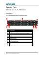
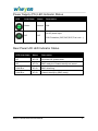
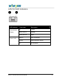
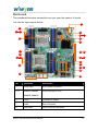
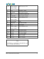
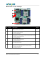
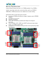
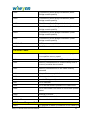
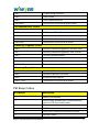
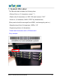
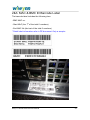
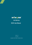
Wiwynn™ SV320 Technical User Manual Version 1.2 Published Nov. 2013 Copyright © 2013 Wiwynn. All rights reserved。 Contents Contents ........................................................................................... 2 System Specification....................................................................... 5 System Tour ..................................................................................... 6 External and Internal Structure .......................................................... 6 Front Panel ........................................................................................ 6 System Status LED Indicator Status ................................................. 7 HDD Carrier LED Indicator Status ..................................................... 7 SAS Backplane Location Map ........................................................... 8 Rear Panel ......................................................................................... 8 Power Supply (PS) LED Indicator Status .......................................... 9 Rear Panel UID LED Indicator Status ............................................... 9 LAN Port LED Indicators.................................................................. 10 Mainboard ........................................................................................ 11 Mainboard Jumper Settings ............................................................. 13 Memory Population Rule ................................................................. 14 Checkpoints ................................................................................... 15 Checkpoint Ranges ......................................................................... 15 Standard Checkpoints ..................................................................... 15 SEC Phase....................................................................................... 15 PEI Phase ........................................................................................ 16 PEI Beep Codes .............................................................................. 19 DXE Phase ...................................................................................... 20 DXE Beep Codes ............................................................................. 23 ACPI/ASL Checkpoints .................................................................... 23 Labels.............................................................................................. 24 Label List .......................................................................................... 24 1. System SN Label ......................................................................... 25 Wiwynn™ SV320 Technical User Manual 2 2&3. MAC & BMC ID Barcode Label ............................................... 26 Warning Messages ........................................................................ 27 Wiwynn™ SV320 Technical User Manual 3 Copyright Copyright © 2012 by Wiwynn Corporation. All rights reserved. No part of this publication may be reproduced, transmitted, transcribed, stored in a retrieval system, or translated into any language or computer language, in any form or by any means, electronic, mechanical, magnetic, optical, chemical, manual or otherwise, without the prior written permission of Wiwynn Corporation. Disclaimer The information in this guide is subject to change without notice. Wiwynn Corporation makes no representations or warranties, either expressed or implied, with respect to the contents hereof and specifically disclaims any warranties of merchantability or fitness for any particular purpose. Any Wiwynn Corporation software described in this manual is sold or licensed "as is". Should the programs prove defective following their purchase, the buyer (and not Wiwynn Corporation, its distributor, or its dealer) assumes the entire cost of all necessary servicing, repair, and any incidental or consequential damages resulting from any defect in the software. Wiwynn™ SV320 Technical User Manual 4 System Specification Form Factor 2U Rack Processor Intel® Xeon® processors E5-2600 series and E5-2600 v2 series Memory Up to 256GB (16 DIMM slots): 2GB/4GB/8GB/16GB DDR3 up to 1600MT/s Chipset Intel® C600 series IO Expansion Five PCIe G3 Slots : One x16 slot ( x8 signals) half-length, half-height Three x8 Slot (x8 signals) half-length, half-height One x8 slot (x4 signals) half-length, half-height Internal Storage Hot-plug Hard Drive Options: 3.5" SAS SSD, SATA SSD, SAS (10K, 15K), nearline SAS (7.2K), SATA (7.2K) Network Port Q’ty : (3) 1GbE , (1) 1GeE management port Controller : Intel I350-AM4 Video Emulex Pilot 3 with 128 MB DDR3 RAM Support System Dimensions 88 (H) * 430 (W) * 660(D) (mm) Weight (min./max.) 26.17kg Wiwynn™ SV320 Technical User Manual 5 System Tour External and Internal Structure Front Panel The illustration below shows the system front panel. 2 1 3 9 8 7 6 Item Component 1 Power button/indicator 2 Twelve 3.5-inch HDD drive bays (HDD#1 to HDD#12) 3 USB port 4 HDD fault LED 5 HDD activity LED 6 HDD carrier latch 7 System normal status 8 System status LED 9 System caution status Wiwynn™ SV320 Technical User Manual 5 4 6 System Status LED Indicator Status LED Color Description Off Amber + Off Blue Power Off Solid Amber + Blinking Blue Pre - AC* Power On* iBMC ready Solid Amber & BlueNon-critical Event AllSolid System Solid Amber + Solid Blue Solid Amber Fan Non-critical Event Temp Non-critical Event Voltage Non-critical Event MEM ECC Fault CPU Thermal trip Shutdown Solid Blue All System Critical Event System Booted & Ready Note: *30 Second BMC Initialization when AC is applied to the server. Power button of front panel is disabled until BMC Initialization is complete. HDD Carrier LED Indicator Status LED Color HDD Status White Off + Red Off Slot Empty White Off or Blinking when Active + Red Off Drive Online White Off or On when Active + Red Blinking Locate White off or Blinking when Active + Red On Drive Rebuild White Off + Red On Array Device Failed Wiwynn™ SV320 Technical User Manual 7 SAS Backplane Location Map Rear Panel 1 2 3 4 5 6 7 8 9 10 11 No. Component 1 Power supply module handle 2 Power supply module 3 Power supply module indicator 4 Power cable socket (110V-240V ; 50-60Hz; 3-6A) 5 Power supply module release latch 6 Serial port 7 Video port 8 USB 2.0 ports 9 Gigabit/management Ports(RJ45) (10/100/1000 Mbps) 10 Gigabit LAN Port(RJ45) (10/100/1000 Mbps) 11 10G SFP+ LAN Card 12 PCI expansion slots Wiwynn™ SV320 Technical User Manual 12 8 Power Supply (PS) LED Indicator Status LED Color State Status Description Green Normal N/A Off Off No AC power input PSU Protection (OCP,OVP, SCP, Fan Lock…) Rear Panel UID LED Indicator Status LED Color State Status Description Off AC Off No power; All system down Off AC On BMC ready, but Chassis Identify not issued Solid Blue AC On BMC Initializing Solid Blue AC On Chassis Identifying (BMC ready) Wiwynn™ SV320 Technical User Manual 9 LAN Port LED Indicators LED indicator Color state Description Green/Amber Off 10 Mbps (Right) Green Solid on 100Mbps Amber Solid on 1Gbps Solid on Active Connection Blinking Transmit/Receive activity Off No Connection Green (Left) Wiwynn™ SV320 Technical User Manual 10 Mainboard The mainboard becomes accessible once you open the system. It should look like the figure shown below. 15 1 2 5 16 17 6 20 21 22 7 23 28 29 32 8 9 12 33 37 13 34 36 38 14 39 No. Connector Description 1 8 PIN PWR 8 pins power connector 2-5 DIMM A0, DIMM A1, DDR3 sockets for CPU DIMM B0, DIMM B1 6 CPU0 Processor 0 socket 7 4 LAN Rear LAN ports 8 VGA COM1 Rear VGA and COM ports Wiwynn™ SV320 Technical User Manual 11 9 -12 DIMM G0, DIMM G1, DDR3 sockets for CPU DIMM H0, DIMM H1 13 CPU1 Processor 1 socket 14 8 PIN PWR 8 pins power connector 15 FAN Connector for system fans 16 24 PIN PWR 24 pins power connector 17-20 DIMM C0, DIMM C1, DDR3 sockets for CPU DIMM D0, DIMM D1 21 PCH (I/O Hub) C602 22 Internal USB USB port (not used) 23-28 SATA 6 SATA ports 29-32 DIMM E0, DIMM E1, DDR3 sockets for CPU DIMM F0, DIMM F1 33 Front USB Front USB connectors 34-36 PCIE X8 3 x PCIe x 8 signals 37 PCIE X4 1 x PCIe x 4 signal 38 Front IO Front IO Header 39 PCIE X16 PCIe x 8 Signals Wiwynn™ SV320 Technical User Manual 12 Mainboard Jumper Settings 1 2 3 4 5 6 No. Jumper Description 1 J1A5 HDD shorted: Chassis cover is closed. HDR open: Chassis cover is removed. Default [1-2] 2 J1D3 Clear System CMOS Information [1-2] 1-2 NORMAL RTC RST (DEFAULT) 2-3 CLR RST REGISTERS 3 J1D7 The user sets this 3-pin jumper to clear the password. The Patsburg SSB [1-2] INTRUDER# pin should be strapped LOW when the password needs to be reset. 1-2 NORMAL OPERATION (DEFAULT) 2-3 CLEAR PASSWORDS 4 J1D8 ME in forced update mode: [1-2] 1-2 NORMAL OPERATION (DEFAULT) 2-3 CLEAR PASSWORDS 5 J3K2 1-2 GPIO CONTROLS WRITE PROTECT (DEFAULT) [1-2] 2-3 FORCE WRITE PROTECT 6 J1E2 When this 3-pin jumper is set, it puts the iBMC Firmware in update mode, which [1-2] enables the user to update IBMC Firmware code when necessary. 1-2 NORMAL MODE (DEFAULT) 2-3 FORCE IBMC UPDATE) Note: Jumpers not indicated are for test purposes only. Wiwynn™ SV320 Technical User Manual 13 Memory Population Rule A given memory channel will have 1 or 2 DIMMs installed. If one DIMM is loaded, Lower digit notation dim socket should be used for ex DIMM A0, DIMM B0 etc. DIMM sockets are color coded also for easier loading. Restrictions within a socket and across a socket No mixing of DIMMs with different voltages, frequency, type (LRDIMM, RDIMM) All DIMMs will have ECC. 8 Ranks per Channel CPU1 and CPU2 (When populated) will always be configured identically. Pairs of DIMMs (A1/B1, A2/B2, etc) MUST be the exact same (same vendor, rev, DIMM Loading Order Independent and locksetp, mirroring and non mirroring & sparing mode, Rank Sparing. C0 C1 D0 D1 E0 E1 F0 F1 B1 B0 A1 A0 Wiwynn™ SV320 Technical User Manual H1 H0 G1 G0 14 Checkpoints A status code is a data value used to indicate progress during the boot phase. A subset of these status codes, known commonly as checkpoints, indicate common phases of the BIOS boot process. Checkpoints are very useful in aiding software developers or technicians in debugging problems that occur during the pre-boot process. Checkpoint Ranges Status Code Range Description 0x01 – 0x0B SEC execution 0x0C – 0x0F SEC errors 0x10 – 0x2F PEI execution up to and including memory detection 0x30 – 0x4F PEI execution after memory detection 0x50 – 0x5F PEI errors 0x60 – 0x8F DXE execution up to BDS 0x90 – 0xCF BDS execution 0xD0 – 0xDF DXE errors 0xE0 – 0xE8 S3 Resume (PEI) 0xE9 – 0xEF S3 Resume errors (PEI) 0xF0 – 0xF8 Recovery (PEI) 0xF9 – 0xFF Recovery errors (PEI) Standard Checkpoints SEC Phase Status Code Description 0x00 Wiwynn™ SV320 Technical User Manual Not used 15 Progress Codes 0x01 Power on. Reset type detection (soft/hard). 0x02 AP initialization before microcode loading 0x03 North Bridge initialization before microcode loading 0x04 South Bridge initialization before microcode loading 0x05 OEM initialization before microcode loading 0x06 Microcode loading 0x07 AP initialization after microcode loading 0x08 North Bridge initialization after microcode loading 0x09 South Bridge initialization after microcode loading 0x0A OEM initialization after microcode loading 0x0B Cache initialization SEC Error Codes 0x0C – 0x0D Reserved for future AMI SEC error codes 0x0E Microcode not found 0x0F Microcode not loaded PEI Phase Status Code Description 0x00 Not used Progress Codes 0x10 PEI Core is started 0x11 Pre-memory CPU initialization is started 0x12 Pre-memory CPU initialization (CPU module specific) 0x13 Pre-memory CPU initialization (CPU module specific) 0x14 Pre-memory CPU initialization (CPU module specific) Pre-memory North Bridge initialization is started 0x15 Wiwynn™ SV320 Technical User Manual 16 0x16 Pre-Memory North Bridge initialization (North Bridge module specific) 0x17 Pre-Memory North Bridge initialization (North Bridge module specific) 0x18 Pre-Memory North Bridge initialization (North Bridge module specific) 0x19 Pre-memory South Bridge initialization is started 0x1A Pre-memory South Bridge initialization (South Bridge module specific) Pre-memory South Bridge initialization (South 0x1B Bridge module specific) 0x1C 0x1D – 0x2A Pre-memory South Bridge initialization (South Bridgepre-memory module specific) OEM initialization codes 0x2B Memory initialization. Serial Presence Detect (SPD) data reading 0x2C Memory initialization. Memory presence detection 0x2D Memory initialization. Programming memory timing information 0x2E Memory initialization. Configuring memory 0x2F Memory initialization (other). 0x30 Reserved for ASL (see ASL Status Codes section below) 0x31 Memory Installed 0x32 CPU post-memory initialization is started 0x33 CPU post-memory initialization. Cache initialization CPU post-memory initialization. Application 0x34 Processor(s) (AP) initialization 0x35 CPU post-memory initialization. Boot Strap Processor (BSP) selection 0x36 CPU post-memory initialization. System Management Mode (SMM) initialization 0x37 Post-Memory North Bridge initialization is started 0x38 Post-Memory North Bridge initialization (North Bridge module specific) Wiwynn™ SV320 Technical User Manual 17 0x39 Post-Memory North Bridge initialization (North Bridge module specific) 0x3A Post-Memory North Bridge initialization (North Bridge module specific) 0x3B Post-Memory South Bridge initialization is started 0x3C Post-Memory South Bridge initialization (South Bridge module specific) 0x3D Post-Memory South Bridge initialization (South Bridge module specific) 0x3E Post-Memory South Bridge initialization (South Bridge module specific) 0x3F-0x4E OEM post memory initialization codes 0x4F DXE IPL is started PEI Error Codes 0x50 Memory initialization error. Invalid memory type or incompatible memory speed 0x51 Memory initialization error. SPD reading has failed 0x52 Memory initialization error. Invalid memory size or memory modules do not match. 0x53 Memory initialization error. No usable memory detected 0x54 Unspecified memory initialization error. 0x55 Memory not installed 0x56 Invalid CPU type or Speed 0x57 CPU mismatch 0x58 CPU self test failed or possible CPU cache error 0x59 CPU micro-code is not found or micro-code update is failed 0x5A Internal CPU error 0x5B reset PPI is not available 0x5C-0x5F Reserved for future AMI error codes S3 Resume Progress Codes 0xE0 S3 Resume is stared (S3 Resume PPI is called by the Wiwynn™ SV320 Technical User Manual DXE IPL) 18 0xE1 S3 Boot Script execution 0xE2 Video repost 0xE3 OS S3 wake vector call 0xE4-0xE7 Reserved for future AMI progress codes S3 Resume Error Codes 0xE8 S3 Resume Failed 0xE9 S3 Resume PPI not Found 0xEA S3 Resume Boot Script Error 0xEB S3 OS Wake Error 0xEC-0xEF Reserved for future AMI error codes Recovery Progress Codes 0xF0 0xF1 Recovery condition triggered by firmware (Auto recovery) condition triggered by user (Forced Recovery 0xF2 recovery) Recovery process started 0xF3 Recovery firmware image is found 0xF4 Recovery firmware image is loaded 0xF5-0xF7 Reserved for future AMI progress codes Recovery Error Codes 0xF8 Recovery PPI is not available 0xF9 Recovery capsule is not found 0xFA Invalid recovery capsule 0xFB – 0xFF Reserved for future AMI error codes PEI Beep Codes # of Beeps Description 1 Memory not Installed 1 2 Memory was installed twice (InstallPeiMemory routine in PEI Core called twice) Recovery started 3 DXEIPL was not found 3 DXE Core Firmware Volume was not found 4 Recovery failed Wiwynn™ SV320 Technical User Manual 19 4 S3 Resume failed 7 Reset PPI is not available DXE Phase Status Code Description 0x60 DXE Core is started 0x61 NVRAM initialization 0x62 Installation of the South Bridge Runtime Services 0x63 CPU DXE initialization is started 0x64 CPU DXE initialization (CPU module specific) 0x65 CPU DXE initialization (CPU module specific) 0x66 CPU DXE initialization (CPU module specific) 0x67 CPU DXE initialization (CPU module specific) 0x68 PCI host bridge initialization 0x69 North Bridge DXE initialization is started 0x6A North Bridge DXE SMM initialization is started 0x6B North Bridge DXE initialization (North Bridge module specific) 0x6C North Bridge DXE initialization (North Bridge module specific) 0x6D North Bridge DXE initialization (North Bridge module specific) 0x6E North Bridge DXE initialization (North Bridge module specific) 0x6F North Bridge DXE initialization (North Bridge module specific) 0x70 South Bridge DXE initialization is started 0x71 South Bridge DXE SMM initialization is started 0x72 South Bridge devices initialization 0x73 South Bridge DXE Initialization (South Bridge module specific) 0x74 South Bridge DXE Initialization (South Bridge module specific) Wiwynn™ SV320 Technical User Manual 20 0x75 South Bridge DXE Initialization (South Bridge module specific) 0x76 South Bridge DXE Initialization (South Bridge module specific) 0x77 South Bridge DXE Initialization (South Bridge module specific) 0x78 ACPI module initialization 0x79 CSM initialization 0x7A – 0x7F Reserved for future AMI DXE codes 0x80 – 0x8F OEM DXE initialization codes 0x90 Boot Device Selection (BDS) phase is started 0x91 Driver connecting is started 0x92 PCI Bus initialization is started 0x93 PCI Bus Hot Plug Controller Initialization 0x94 PCI Bus Enumeration 0x95 PCI Bus Request Resources 0x96 PCI Bus Assign Resources 0x97 Console Output devices connect 0x98 Console input devices connect 0x99 Super IO Initialization 0x9A USB initialization is started 0x9B USB Reset 0x9C USB Detect 0x9D USB Enable 0x9E – 0x9F Reserved for future AMI codes 0xA0 IDE initialization is started 0xA1 IDE Reset 0xA2 IDE Detect 0xA3 IDE Enable 0xA4 SCSI initialization is started 0xA5 SCSI Reset 0xA6 SCSI Detect 0xA7 SCSI Enable 0xA8 Setup Verifying Password Wiwynn™ SV320 Technical User Manual 21 0xA9 Start of Setup 0xAA Reserved for ASL (see ASL Status Codes section below) 0xAB Setup Input Wait 0xAC Reserved for ASL (see ASL Status Codes section below) 0xAD Ready To Boot event 0xAE Legacy Boot event 0xAF Exit Boot Services event 0xB0 Runtime Set Virtual Address MAP Begin 0xB1 Runtime Set Virtual Address MAP End 0xB2 Legacy Option ROM Initialization 0xB3 System Reset 0xB4 USB hot plug 0xB5 PCI bus hot plug 0xB6 Clean-up of NVRAM 0xB7 Configuration Reset (reset of NVRAM settings) 0xB8 – 0xBF Reserved for future AMI codes 0xC0 – 0xCF OEM BDS initialization codes DXE Error Codes 0xD0 CPU initialization error 0xD1 North Bridge initialization error 0xD2 South Bridge initialization error 0xD3 0xD4 Some of the Architectural Protocols are not available PCI resource allocation error. Out of Resources 0xD5 No Space for Legacy Option ROM 0xD6 No Console Output Devices are found 0xD7 No Console Input Devices are found 0xD8 Invalid password 0xD9 Error loading Boot Option (LoadImage returned error) 0xDA Boot Option is failed (StartImage returned error) 0xDB Flash update is failed 0xDC Reset protocol is not available Wiwynn™ SV320 Technical User Manual 22 DXE Beep Codes # of Beeps Description 1 Invalid password 4 5 Some of the Architectural Protocols are not available No Console Output Devices are found 5 No Console Input Devices are found 6 Flash update is failed 7 Reset protocol is not available 8 Platform PCI resource requirements cannot be met ACPI/ASL Checkpoints Status Code Description 0x01 System is entering S1 sleep state 0x02 System is entering S2 sleep state 0x03 System is entering S3 sleep state 0x04 System is entering S4 sleep state 0x05 System is entering S5 sleep state 0x10 System is waking up from the S1 sleep state 0x20 System is waking up from the S2 sleep state 0x30 System is waking up from the S3 sleep state 0x40 System is waking up from the S4 sleep state 0xAC System has transitioned into ACPI mode. Interrupt controller is in PIC mode. 0xAA System has transitioned into ACPI mode. Interrupt controller is in APIC mode. Note: Checkpoints may differ between different platforms based on system configuration. Checkpoints may change due to vendor requirements, system chipset or option ROMs from add-in PCI devices. Wiwynn™ SV320 Technical User Manual 23 Labels This system comes with related labels attached to the machine and packaging for your information. In this chapter, the label list and the location of the labels will be illustrated. Label List Item Label Name Qty 1 System SN Label 1 2 MAC ID Label 2 3 BMC ID Label 1 Wiwynn™ SV320 Technical User Manual 24 1. System SN Label The barcode label includes the following item: - Wistron Part no. (11 characters, except ".") - Week code (3 characters) ex: 2010 16th week means: "016" - Serial no. (5 characters, 00001~FFFFF by Hexadecimal) (Every week should be arranged from 00001, and arrange by part no.) - Manufacturing Code (2 characters), WZS is "J0" - Engineering Version (2 characters) * Detail label information refer to PE document. Only a sample: Wiwynn™ SV320 Technical User Manual 25 2&3. MAC & BMC ID Barcode Label The barcode label includes the following item: - BMC MAC no. st - Start MAC (the 1 of the total 6 numbers) - End MAC No (the last of the total 6 numbers) * Detail label information refer to PE document. Only a sample:: Wiwynn™ SV320 Technical User Manual 26 Warning Messages Incorrect replacement of the lithium battery may lead to a risk of explosion. The lithium battery must be replaced with an identical battery or a battery type recommended by the manufacturer. Do not throw lithium batteries into the household waste. They must be disposed of in accordance with local regulations concerning special waste. Removing a hot-swap power supply When you remove or install a hot-swap power supply, observe the following precautions. CAUTION: The power control button on the device and the power switch on the power supply do not turn off the electrical current supplied to the device. The device also might have more than one power cord. To remove all electrical current from the device, ensure that all power cords are disconnected from the power source. Wiwynn™ SV320 Technical User Manual 27 CAUTION: Never remove the cover on a power supply or any part that has the following label attached. Hazardous voltage, current, and energy levels are present inside any component that has this label attached. There are no serviceable parts inside these components. If you suspect a problem with one of these parts, contact a service technician. Wiwynn™ SV320 Technical User Manual 28 有關伺服器、儲存、電源、網路和機櫃產品 在安裝產品前請先閱讀 記住並遵守有關產品安全性與操作的所有說明。請隨時參考設備提供 的操作說明 (平面或電子檔操作說明)。如果本指南與設備操作說明有 出,以設備操作說明為準。詳細閱讀產品上及操作說明裡的所有注意 事項。 為避免受傷、觸電、引起火災及設備受損,請仔細閱讀本指南所列的 所有注意事項。 設備上的符號 下列符號可能會出現在設備上,表示潛在的危險情況: 這個符號和下列符號一起出現時表示有可能發生危險。如果沒有 仔細閱讀注意事項,可能有受傷的危險。請參考操作說明以穫得 明確的資料。 這個符號表示能源線路有危險或有觸電的危險。請向專業人員尋 求維修協助。 注意:為避免觸電受傷,請不要打開外殼。請向專業人員尋求保 養、升級和維修等協助。 這個符號表示有觸電的危險。這部份不會需要使用也不會需要維 修。無論什麼原因都不要打開。 注意:為避免觸電受傷,請不要打開外殼。 Wiwynn™ SV320 Technical User Manual 29 在 RJ-45 插座上的符號表示網路介面連結。 注意:為避免觸電、引起火災及設備受損,請勿將電話或電信插 頭插入此插座。 這個符號表示表面或零件過熱。如果接觸到這個表面,有可能有 燙傷的危險。 注意:為避免接觸到過熱零件而燙傷,請等表面冷卻再接觸。 電源供應器或系統上的這些符號表示供應設備的電力來源有許多 種。 注意:為避免觸電受傷,請拔掉所有的電線,完全切斷系統的電 源。 這個符號表示該零件的重量超出一個人安全處理的建議重量。 注意:為避免受傷或設備受損,請仔細了解當地對手動處理材料 的職業健康和安全性需求與指導方針。 Wiwynn™ SV320 Technical User Manual 30 甲類警語及 Label 位置大小 cm Wiwynn™ SV320 Technical User Manual 31 一般注意事項 保養和維修企業級商品的注意事項 警告 本電池如果更換不正確會有爆炸的危險 請依製造商說明書處理用過之電池 電池 請勿嘗試替電池充電 請勿將電池曝露在超過 60 度 C (140F)的溫度下。 請勿拆解、壓壞、戳破電池,也不要讓電池短暫與外界接觸,或 者置於火中或水中。 Wiwynn™ SV320 Technical User Manual 32