1
--
.
nl ~n@
" .
',~"
", '\:..
,"
..
\'
~
,",
"6:\
.~.\
':,.;\
"
10"""'«' ",,;>~2<""'" ,,~. ~""'"
0" , "', ",~",.,.".>""'"
'
'"
1>"
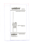
MC 790
MARINE RADIOTELEPHONE
OWNER'S MANUAL
--q:::
1-"------
>:'
'~:
:::
<::::
.',,'",:',UNIDEN:MC790",,:'>:"
::'.;:,',",',.>",',:,"
The UNIDEN
transceiver
a rugged
VHF marineradio
MC790
has
been
designed
reliable instrument
to give you
that will
vide you with years of
trouble-free
You
to thoroughly
are encouraged
this manual
to acquaint
pro-
se Nice,
read
yourself with
"",:"
,
signed into this quality transceiver will
prevent itfrom becoming
obsolete regard-
less of changes in craft or geographic
locations. The unit may be mounted in
any number of convenient locations by
utilizing the universal mounting bracket.
the
isof allsolid
state
characteristics
and operation of your tran-
The UNIDEN MC790
sceiver so that you
design with conseNatively
rated rugged
componepts
and materials
compatible
with the marine environment.
The transceiver utilizes a number ofgaskets, sealing
rings,. waterproof
membranes, and other
sealants to effect a splash proof housing
for protection of the electronics.
can contribute
to the
longevity of your investment.
With proper care and maintenance, Y0ur
UN/DEN MC790 will outlast your present
vessel andseNe you well on, board several
more. The full feCltures and flexibility de-
,I,
,
"
,
""
'
,":,~:INSTALIATI()N'"
'
>
"
r
,
-,
-,-
--....---------
CAUTION: The MC790 will operate only with nominal J2 volt negative ground
battery systems,
It is important to carefully determine the
most suitable location foryour MC790 on
your vessel. Electrical, mechanical, and
environmental considerations must all be
taken into account. You must select the
optimum relationship among these considerations.
~~
Keep in mind the flexibility designed into
the MC790 so that you can most conveniently use your radio. Features
which
should be considered are:
,.
~
"
J. Universal
mounting
2, The microphone
connector
ward allowing convenient
"built-in" installations.
faces for-
in-dash or
3, The front panel can be fully reversedto
for optimum viewing and
operating forany mounting position.
provide
4, The
REMOTE
speaker
jack
may
be
used with an auxiliary speaker,
All
connections are "plug-in" type for
easy removal of the radio.
bracket may be
installed on either top or bottom of
shelf, bulkhead,
or overhead
mounting.
;
I'
, !
,
J
"
f
,
J
-- -..
--
!
I
--
~r
-----
1
'
I
---,
=--~'~-'"
)
A variety of antennas is available from a
number of quality suppliers. It is recommended you draw upon the advice of
your Marine Dealer in determining a
suitable antenna for your vessel and
range.
requirements.
'
.
::
The general
rulesi for antennas are The
.
more g~j/n the greater the range and, the
higher above the water line the greater
the range. Antennas should be located so
as not to be in proximity to metal or'wets.
Antennas should not have excc~..::.ively
long coaxial feed cab/cs.
.
rlo N
',"
,
~",.;.":'.~'..'..'':;o::C:H,
Some of the more important external factors to consider in selecting the location
of your MC790 are:
'"':':':':,.
.'
:','::'~:U;~~;~L,:
'"
"""",,
','
".-,'h
';,'::,/.;~;;:;~n.;:.:...
7. Select a location well away frorn the
ship's compass. Auxiliary speakers also
should be located away from the com-
pass,
1. Select a location that is free from spray
and splash.
After you
have cc!refl1l1y consicJerc(j
the
various factors affecting your choice of
2. Keep the battery leads as short as possible. Connection
directly
to the
battery is most desirable. If direct
connection cannot be made with the
supplied r power lead, any extension
should be made with # 10 A WG wire.
Long extensions should use larger
wire.
3. Keep the antenna lead as short as possible. Long antenna leclcJs CZlrl cause
substantial
loss of performance
for
both receiving and transmitting.
antenna as high as possible and clear from metal objects. The
reliable range of coverage is a direct
function of antenna height.
4. Locate your
5. Select a location that does not allow
the radio to be subjeCted to direct sunlight (including that coming through
windows).
location, position the radio (wi(i! the
bracket,
microphone,
power
iJlug,
antenna
plug and any auxiliary plugs
installed) into the selected location to
assure, there is no interference with surrounding items. Mark the location of the
mounting bracket.
Remby~ ,the bracket fror:n the racJio and
use itas a template to mark the hole') to
be drilled for the mounting
rlc!rc!wcIre.
Drill the holes and mount the br,]cket
with hardware compatible with the material of the mounting
~urface. fnst;l:1 the
power
cable (red f~ +, black 1\ -I,
antenna and all other auxiliarycables and
accessories.
Install
the
radio
into
the
mounting
bracket and connect all cables an(j (~ccessories to the
connecrors.
apprf)priate
jacks
and
6. SeleCt a location that allows free air
flow around the heat sink on the rear
of the radio.
r
-
--
~
-
---- --[--
--
~~~.
'-"---'
-~
-
6
i.1fj1;~lli~..':~;1!;t;/.;:~,;
j;J'~J);'.~k~~~:,.1
ti';
~,~,~..~~
;;ilf:.'JI.".:':..,.;.~
I.,
CID
CD Microphone
Connector.
your Microphone here.
(~) ON/OFF
VOLUME
. . Plug
Knob...
Turns power on and adjusts volume level.
\'
@ SQUELCH Knob.
. . Used to silence the backGround noise when no
signal is being received. Turn the knob
just past ttle point where background
noise stops.
.'
C£'DIM Control.
. . Adjusts the brightnesS' of both LCD and the keyboard
back lighting for night operation.
(~ Key Board. . . Selects the desired
channel.
LCD display shows CH- ]
through CH-88. Forchannels ] through
9, firstyou must depress "0" then the de;sired channel number. Ifyou attempt to
enter CH. 75, 76 and channels other
than VHF marine channels, which are
Ch. 29 - 59, and 89 - 99, the letter "E"
will flash in the LCD display and also
"70" will flash when Ch. 70 is selected
for transmit on international channels.
To continue normal use of the radio,
make a proper channel selection.
. . . Provides indication of ch annel and function even in brightest sunlight.
@ LCD
T
.,.--.
--
-
rt-.
--
=.~,c~~--~=
<:::
---
-
"-"---
=
~=
"
CD
REMOTE
Speaker
Connector
. . .
If you desired to use anol/ler
speaker in C)ddition to the one in the unit, a four or eight ohm speaker equipped
with a miniature phone plug may be
conneCted to, this jack.
~ DC Power Connector.
. . Battery
connections are to be made with the
cable supplied to mate with this con~
nector. Remember, red is +, black is-,
The power cord ;s equipped with a fuse
to protect the radio. Use only a Six (6)
AMPEREfast blow fuse for replacement.
Note: Tile racJio must lK' connected
lCI,1
power source (or LIlt' nJ<'IIJory to fw1i ll()(}
properly. Remember nor"~o disconneCL ll"1e
power cable, or you will lose the memory.
However, when this unit is not going (0 tJe
used for a long period of time, be SUfC'10
disconnect the power cclble for safety tJecause the current of less than 1mA is fee! for
memory back-up even after the radio is
OFF. (But in this case, you will lose tfle
memory.)
@ ANT Connector.
. . This connector is for connection of the antenna. A
type PL259 connector is required to
make proper connection.
'.'.
---
"---- - _. -
----
"--.
-----------
--
------
;:: :'.,:~:,,",)'.
",'
.
,: ':':'cARE',:ANDMINTEI\tANCE,'
Your MC790 is a precision piece of electronic equipment and you should treat it
accordingly. Due to the rugged design,
very little ma,intenance
is required,
however, a feJJ precautions should be
obseNed,
.'
" ,
',:~
~
If the antenna has been damaged, you
should not transmit except in case of
emergency.
A defective antenna may
cause damage to your radio.
Ifyour radio has been accidentally subjected to splay or splash you should immediatelywipe it down with a soft cloth dampened
with fresh water,
1"
......
(
,i
, I
, !
--
---
'.-
-.-
-
:
i f
r1--
,:'KEI:;'FUNcnoi\t.'::..
.' "'.":,
u
:.,.,...~",.t-, '. " :.. . . '.
This key turns on the Memory Scan and gives you "SCAN" on LCD, j: tile
squelch is in operation and Scan Memory Channels are programmed,
Scan
starts its operation
While it is on, the second digit of the channel nuf,'ber
shows movement indicating that the Scan is on.
When the radio receives a signal on a programmed
channel while MC'11Orv
Scan is on, and squelch opens, it indicates its channel number and Sldy' , 0;
that channel. \X/hen the signal is gone, squelch closes and Memory Sc;m is
reaCtivated.
[MANU'
J
l
This key ;s used to check Memory Scan or when all the memory SCc1:1is
deleted. It is also used when "0" is flashing by mispressing the scan key
with no channel number programmed in memory scan. If you pres:; this
key in a normal operation, it shows each channel number programmccJ in
Memory Scan.
['"TER
This is the key to turn on the Memory Scan Channel. Select the char1nel
you wish to program, then press the ENTER Key.i'MEM" is indicated on
the left hand of the channel number to indicate that the program is completed.
LElETE
This key deletes the programmed Memory Scan Channel(s). When this key
is pressed, the lowest numbered channel in the Memory Scan is indicated
and deleted. If you keep pressing it. the next lowest channel numtJcr is
ir1dicated for deletion. "0" flashes whenall the memory scan channel:; are
deleted.
]
Co-J
\
D~L
[,w~L
J
]
r
:.~
. .
This key gives you international cllannels or USA channels with an indication of "INT" or "USA" on the display. When the radio is activated,
international channels are auromarieally available and by pressing the key,
it goes ro USA channels
'-
l
US~NTJ
L~J
(87 AI
L_J
This key gives you instant access to channel 16 and "'J6" will be indicated
on LCD when you press it.
This key gives you instant access to channe/87A
and "87" will be indicated on
LCD when you press it. If channel 87A is seleCted from keyboard while operating USA. channels, LCD WILL FLASH" u",
I.
Thttse keys arc used (0 progr;:HT1cll<tnnel numbers.
Tlw first numl)cr you
press becomes rile first digit, and if the second digit ,~ not progr.:wirned
within 10 seconds after the first one, it returns to lhe previous channel.
When the seleCted channel number does nOt exist, "E" flashes.
~
I
'."','
By pressing this key, "DUAL" is indicated on the display. Every one and ci half
seconds, it monitOrs CH 16, If the receiver hearsa signal on CH ] 6, it locks ontO
that channel.
Wt,en the signal stops, it returns ro monitoring CH) 6 ('very
one and a half seconds. "DUAL" can be operated along with Memory Sc,m.
By pressing the "DUAL" key, it can be cancelled.
By pressing this key, the power out-put can be changed to 1Wand ir WI!Ibe
indicated on LCD. By pressing this key again, the power out-put returns (0
25W and the indication on LCD will be turned off.
NOTE:
The MC790 has a self-check function to indicate malfunCtions due to overly high
incoming nj;)jse leve/sand sudden, drastic changes of power voltage levels wllen the
unit is on. This self-check will illuminate all segments of the LCDwhen triggered. If
tllis should occur, t?urn unit off, then back on to rese[ rhe microprocessor chip. The
programmed functions will not be erased as long as the Back-up BaneI)', is functioning.
Plea'se read the Owner's Manual carefully before operating your unit.
.
=-
-_.-
.
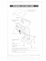
(2) TURN UNIT OVEfi ANO CAREFULL
REMOVE COVER CABINET
PULL UP FROM REAR FIRST.
~NET
(3)
SPEAKER
//
'-":::":;'.,
1"
DISCONNECT
WIRES.
l,
/I/
/
11/ ~
Y
//
/.
(5) REMOVE TWO SCREWS
HOLDING FRONT PANEL
TO CHASSIS.
(6)TILT
FRONTPANEL.
(7) REPLACE FOUR
SECURE FRONT
CHASSIS.
(4) REMOVE
SPEAKER
SCREWS TO
PANEL TO
I
1
CABINET.
I
(1) REMOVE FOUR SCREWS
FROM SPEAKER
". CABINET.
1
(8) CAREFULLY
REPLACE
CovER
CABINET
BUT ON BOTTOM
PANEL FIRST AND THEN LOWER AT REAR OF RADIO.
(9) TURN
RADIO
OVER
AND nr:CONN[CT
(101 HEPOSITION
SPEAKER
THE HOUSING.
(11) RETIGHTEN
FOUR
CIIBINET
APPEARANCE
SPFAKUi
COVER
- -
,..",
WIRe
ON TOP OF RADIO
OF RADIO
INSERT
UNDER
FROWi
I FIIDS
AND REPLACE
FOUR
SCHE.WS TO SECUH:.
SCREWS.
-
.-
T
---
- ---
-
---
--
[-
,-""
-~
...------.
~u-
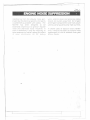
Interference from the impulse noise generated by the electrical systems of engines
is sometimes a problem with radios. The
MC790 has been designed
to be
essentially impeNious to ignition impulse
noise and alternator noise. However, in
some installations it may be necessary to
take measures to further reduce the effect
of no;.<;c interference. All DC t)auc(y
wires, antenna lead, and accessory cables
should be routed away from the engine
and engine compartment and from power
cabling carrying particularly high currents.
In severe cases of Lmpulse noIse interference, it may be necessary to install a noise
suppression kit that is available from your
M':Hinc DCcl/er.
"
1}
I..
"
t;-~
...
i
I: I.
li'
I! !
T
-
- -
r
------ i
,
--,
~"-
<:
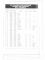
CHANNEL
DESIGN
-;--_.
02
03
04
05
06
07
OH
09
10
11
12
13
14
15
16
17
18
19
20
21"
22
23
24
/5
2(,
27
28
60
61
62
63
64
65
66
67
68
69
70
71
n.
73
74
77
78
79
80
81
82
83
84
85
86
87
88
I
I
I
,...,
FREQUENCY
,
SHIP
II
I
56.050
156.100
'I
.)
1
I
I!
i
I
i
II
I
i
II
I
I
!
i
I
I
I
i
i
:
i
;
Ii
,--..--.
.
I
156.
150
56.200
156.250
(MHzJ
156.150
) 56200
156.300
I c;t>.''jO
1'd, '100
1%.300
I :,t, 'I',n
I ',t, ,i()tJ
,j6.450
156.450
156,500
156,550
156.600
156.650
156.700
156.500
156.550
156.600
156.650
156.700
-
156.800
156.850
156.900
156.950
157.000
157.050
157.100
157.150
157.200
':;7.7.50
15/.300
157.350
I 5 7.400
156.025
1'56.075
) 56.125
156.175
) 56.225
156.275
1567.S
156375
! 56,425
156.475
156.525
156.575
156.625
156,675
156.725
156.875
;
i
SHIP
TO SHIP
I
--'----'-'1-"--"-'"
-.. --.... .,--- ---.
I
156.050
VIS
i POr! Ops
156.100
i
156.250
!
TYPE
TRAFFIC
---'-1
SHORE
156.750
15(.800
156.850
1%.900
156.950
161.600
157.050
157.100
157.150
161 ROO
1(, I lJ',tJ
16 I. 'lOO
16/.950
162.000
156025
156.075
) 56.125
) 56. 175
) 56.225
156.275
156.37<;
156.37'.>
156.425
156.475
156.525
156.575
15667.5
156.675
156.725
156.875
-
-,..
Port Ops
I
'
:
;
;
:
I
I
I
,
'
I
,
Yrs
Ye
Ye.',
Yes
S,lfciy
( ,\1,,'1
Y""
Y"',
Y.."
Yes
I
Yes
Com"
Com"
f'ort Ops
Navigational
Par! Ops
Environment,l'
Yes ','
Yes
S, fC I Y (:11111 Jq
Y,.\
Y,'\
Yes
Yes
Yes
Yes
Yes
Yes
Yes
Nu
Yc\
Yes
Yes
Ycs
Yes
Yes
Y('s
Y,".
'("',
Y,",
Yes
Yes
Port Ops
POri Ops
Corn"
Non Com',
Non Corn"
Non Corn"
Non Corn"
Non Com"
Port Ops
Port Ops
Pan Ops
i
"
'
tJ..
tJu
No
No
.
Yes
Ycs
Ycs
Yes
Yes
Yes
Yes
Yes
Yes
Yes
Yes
i
'
:
:
!
'
'
i
I
' 56.925
1692
Non (om"
Yn
156.975
157.025
157.075
) 57. 125
157.175
157.225
157.275
Yc
156.975
157.025
157.075
) 57. 125
157.) 75
161.825
16/.875
Corn"
Corn"
Coast Guard
US Gov Only
(oasl Guard
Public Corresp.
Public Corresp.
Yes
Yes
Yes
Ycs
Yes
No
No
Yes
Yes
Yes
Yes
Yes
Yes
!
157.325
J61.925
157.375
J57.425
16/975
162.025
'
,
I
,
1
Public Corresp.
No
i Yes
Yes
Public Corresp.
Com"
No
Yes
Yes
No
Environment
,
!
Yes
Yn
No
Yes
Yes
No
Yc.s
No
Yes
Yes
No
CO,,,,! C;IJ,!Ii!
hsl1
Yes
Yrs
Yes
Yes
Yes
RX Onl,'
SIdle (ontrol
Com"
Corn"
Por! Ops
Coast Gu,Jrd
Coast Guarc
Coast Guard
PIJI)I,( (or((",('
"ul,l" <'011(",1'
Pt/DI'l (0"":,/1
Public Corresp
PubliC Corresp.
I
,
Ne.
Y,".
N"
Yes
Yes
Yes
Yes
Yes
Yes
RX Only
,
PERMANENT
SCAN LIST
. - ..... ...--....-
Y('
VIS
! ("""
(0111"& Non Corn',
:
........,_.h
Ycs
Ye:.
i' Port Ops
!
'I
SHIP
TO SHORE
c',i
Coast GU,'flJ
Coast Guard
Coast GU,l((;
I1I1'.Yl,"
fjIJ"Y I,"
Uuyl('i.
Busy Tei.
Busy Tel.
Flstl
Fish
Fish
Fish
Fish
,
i
11
I
!
FISh
I
Coast Guard
Ii
Coast Gu<\((
Busy Tei.
:
Busy Tel.
Busy Tel.
Busy Te'..
Busy Tel.
r
{
--
~
I
-
---
--
~
$
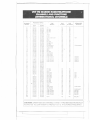
nCHANNEL
_.'.~_E_~~GN
0I
02
I
!
FREQUENCY
-.-l=~---~;~~--~_.! ~~~;~
I 156.050 i 160.650
:
156. I00
03
04
i
156.150
156.200
05
0(,
'156.250!
1
1')6.300
i
(Jt
011
09
10
11
12
13
14
J5
16
17
1~
19
20
21
22
23
I',{,'!';n
1
,. ''
I
I
I
1
1
I
I
I
'
I
",(,'100
156.450
~
i
I
156.550
156,600
156.650
156.700
156.750
156.BOO
156.850
156.900
156.950
157.000
157.050!
157.100!
157.150
l()
27
28
60
61
'~{)O(J
157.:150
64
65
66
67
157.400
156025
156.075
68
69
70
71
72
73
74
77
713
1156125
I
156.175
1
,156.225
!
i
~
iI
!
I
156.275
"'156.325
156.375
156.425
156.475
156.575
156.625
156.675
156.725
156.875
I.,. ,156,925
79
80
81
82
I
I
I
156.975
157.025
157.075
157.125
83
84
85
86
87
87A
88
i
157.175
157.225
157.275
157.325
:
~:.
! VTS
: Pan Ops
160.750
. Pan Ops
160.800
160.B50
'I Pan Ops
I VTS
156.300
'
i
i
i
I
'
~dtcty
(,,","
",{, '100
156.450
156500;
((JIII',
Corn"
& Non Cam',
Corn',
156550
) 56.600
156.650
156.700
156.750
Corn'l
Pon Ops
Navigational
Port Ops
Envlronmenta'
]57.375
157.375
157.425:
.
15(JfiOO
156.850
161.500
161.550
16 1.600
161.650
161.700
161.750
i
i
Coast Guard
'
I{,III',(J
:
1""J"',(O"""p
I
161.950!
1
i
iI
I
I
I
1{,lnOO!
161.')()O
162.000
160.625
160.675
1160.725
!
160.775
I 160.825
I
160.875
I 160925
I 156.375
I 156.425
I 156.475
,156.525
I
i
:'i
156.575
156.625
156.675
156.725
156.875
161.525
I
II
I
I
I
i
I
SHIP
TO SHIP:
--- on. _.
If,n'I',()
161.575
161.625
]61.675
161.725
161.775
161.825
161.875
161.925
I
I
... .-.
160.700
I
62
63
TYPE
TRAFFIC
I
IS7.l00
,~,//')()
:
:
156.500
74
/~,
I
!
i
"
{MHzJ
161.975
157.375
162.025
S;.dr'ly Cllllne)
StdtC Control
, Corn"
,Corn"
Port Ops
:; Coast Guard
: CoastGuard
f'ul)l,rCC)r(('~,p
!
1"UIJlic(orrc',p.
:
Public Corrc>sp.
'
Public Corresp.
-0--'
.'-'
i
1-'
Yes
Yes
Yes
Yes
Ycs
Ye~
Y"',
SHIP
TO SHORE
!
Yes
Yes
Ycs
¥es
I
Yes
Yes
Yes
Yes
No
Y'""!
:
Nu
:
Yes:
Yes
Yes
I
i
i
Yes
Yes
Yes
I
Yes
Yes
Yes
Yes!
Yc~
Yes
Yes
Yes
Yes
Yes
I
Yes;
Yes"
Yes
Yes
Yes
Ye~
Yes
Yes
Yes.
Yes!
Yes
No
Yes
NrJ
No
No
No
I
PERMANENT
SCAN LIST
,
I
I
i
:
¥n
I
I
Yc\
Yes
Yes
Yes
,
!
i
!i
i
I
i
!
Fisll
I
Environmental
I
I
i
I
i
I
I
I
f3IJ\Y
I3IJ\Y
Busy
Busy
Busy
Tel.
Tel.
Tcl.
Tel.
Tel.
,
i
I
I
;
Pon Ops
i
Pon
i
Op~
Com'l
Non Com'l
Non Corn"
Non Corn"
Non Corn"
Non Corn"
Pon Ops
Port Ops
Pan Ops
Non Corn"
Corn"
Corn',
COi1st Guard
US Gov Only
Coast Guard
Public Corresp.
Public Corresp.
Public Corresp.
Public Corresp.
Corn"
Yes
Yes
Yes
Yes
Yes
Yes
Yes
Yes
Yes
Yes
YC's
Yes
Yes
Yes
Yes
Yes
Yes
No
No
No
. No
Yes
Yes
Yes
No
Yes
Yes
No
Yes
1>10
Yes
Yes
No
Yes
Yes
Yes
Yes.
Yes
Yes
Yes
Yes
Yes
Yes
j
,i
,I
!
I
!
.
No
I'
I
/
Fish
Fish
' Fish
Fish
Fish
I
I Coast Guard
I
I
CoastGuard
I
Busy Tel.
Busy Tel.
8usy Tel.
Busy Te/.
Busy Tel.
1
!
I
I
I
CAUTION: OPERATION ON CHANNELS] 5 AND] 7 HAS BEEN ELECTRONICALLY
RESTRICTED TO LOW POWER TO PROTECT CH, 16, THE DISTRESS FREQUENCY.
:r
J
----.-
~r
~~
<::
~
.
-
=
I
".
:
-
'
SPECIFI"""' IONS
,"'..""
'.
.""'.,"-.'..,.,,':"';;
...;,~:;,~;,,;:,:.,,~,~..,
""":""""
'-"I,'
GENERAL
Channels
"'.,:;,,(,
<;,',::' ..:::~::
"'::">:'."'~>:':\~
.
IJI
1q\-~:r:
::,":,":';:":~'.if...:',
"":':::.",,:'~/~,jV:.'::'
: Transmit 55
Frequency Control
Method
Antenna Impedance
Speaker'
Microphone
Receive 80
: PLLsynthesizer
: ~O ohms, nominal
: 2.85 inch, 8 ohms
: Rugged 600 ohms dynamic element with coiled cord
and plug-in connector
:L.c.D
Channel Display
. :to.001%
Frequency Stability
Operating Tempera- : :t 20°C to + 50°C
ture Range
Shock and Vibration : Meets or exceeds EIA standards, RS] 52B and RS204C
Size
: 7-1/4"W (185m/m) x 9-5/8"L (245m/m) x 2-1/4"H
(58m/m)
: 1.6 kg
Weight
Controls
Connectors
Frequency Range
: On-Off/Volume, Squelch & Dimmer controls, ;Key Board
: Antenna, microphone, remote speaker. DC power
: J56 to J58 MHz transmit
156 to J63 MHz receive
Lights and Indicators:
Channel Number, ITXI , 25W, IW, USA, 1NT, DUAL,
SCAN, MEM, Backlight Key Board & LCD,
Standard Accessories:
Plug-in microphone,
mounting bracket and hardware,
DC power cord, mike hanger, spare fuse, owner's
manual
: J3.8V DC negative ground
Supply Voltage.
.
TRANSMITfER
Power Output
Power Requirement
!
: 25 or I watt (keypad selectable)
: 25 watts output: 5.0A ~I 13.8V DC
I wan output:
I.OA
: FM, :t 5 kHz deviation
: 40 dB
Modulation
Hum and Noise
Attenuation
Audio Distortion
~I'
13,8V DC
: Less than 5% with 3 kHz deviatjon with] 000 Hz
modulating frequency
: -70 dB
: Built-in
Spurious Emission
Output Transistor
Protection
Output Power
Stabilization
: Built-in automatic level control (ALC)
!!!!!I!
T
..
J
-
-
-
---
--['
-~..-...
--=
""'~-..
<::
SPECIFIt'ATIONS:'
RECEIVER
Sensitivity
Threshold Squelch
Sensitivity
Tight Squelch
Sensitivity
Spurious Response
Attenuation
Image Response
Attenuation
Intermodulation
Attenuation
Adjacent Channel
Rejection Selectivity
':~~'"
: 0.35,.uV for 12 dB SINAD
0.50pV for 20 dB SIN
: 0.20pV (EIA method) : 2.01-lV (EIA method)
: 75 dB
: 75 dB
: 65 dB (~11
12 dB SINAD
: 70 dB (EIA method)
: ::t 7.5kHz (a,6 dB down
::t 15 kHz ((I 60 dB down
Audio Output Power: 3.5 watts minimum at J0% distortidQ at } kHz modulation and::!: 3.5 kHz deviation (4 ohm speaker)
Power Requirement
- : O.6A ((11I3.8V DC squelC[led
J.2A ((pI 3.8V DC at r~Hcd audio output
": Jst-c-21.4MHz
.
IF Frequencies
2nd455 kHz
Hum and Noise Level: -50 dB (EIA method)
"'~
.'
I":
I
ii
'. , .. I';
I
i! I:
,-
\,
--.---.-
~
]1---
--- --- --- - --- ~
-
f
-