1
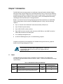
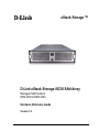
xStack Storage TM D-Link xStack Storage iSCSI SAN Array Managed SAN Solution DSN-3200 & DSN-3400 Hardware Reference Guide Version 1.0 © 2008 D-Link Networks, Inc. All Rights Reserved D-Link Systems, Inc. makes no warranty of any kind with regard to this material, including, but not limited to, the implied warranties of merchantability and fitness for a particular purpose. D-Link Systems, Inc. shall not be liable for errors contained herein or for incidental or consequential damages in connection with the furnishing, performance, or use of this material. This document contains proprietary information, which is protected by copyright. No part of this document may be photocopied, reproduced, or translated into another language without the prior written consent of D-Link Systems, Inc. The information is provided “as is” without warranty of any kind and is subject to change without notice. The only warranties for D-Link products and services are set forth in the express warranty statements accompanying such products and services. Nothing herein should be construed as constituting an additional warranty. D-Link shall not be liable for technical or editorial errors or omissions contained herein. Copyright © 2008 D-Link Systems, Inc.™ Trademarks Adobe® and Acrobat® are trademarks of Adobe Systems, Incorporated. Java™ is a U.S. trademark of Sun Microsystems, Incorporated. Microsoft Windows is a U.S. registered trademark of Microsoft Corporation. Oracle® is a registered U.S. trademark of Oracle Corporation, Redwood City, California. UNIX® is a registered trademark of The Open Group. All other brand or product names are or may be trademarks or service marks, and are used to identify products or services, of their respective owners. D-Link Systems, Inc. 17595 Mount Herrmann Street Fountain Valley, CA 92708 ii Safety Information There is a danger of a new battery exploding if it is incorrectly installed. Replace the battery pack only with the same or equivalent type recommended by the manufacturer. Do not dispose of the battery along with household waste. Contact your local waste disposal agency for the address of the nearest battery deposit site. This product also uses a lithium coin cell battery. The lithium coin cell battery is a long-life battery, and it is very possible that you will never need to replace it. However, should you need to replace it, consult your service documentation. Do not dispose of the battery along with household waste. Contact your local waste disposal agency for the address of the nearest battery deposit site. Following are the safety agency certifications that the xStack Storage enclosure has met: CSA 60950-1 UL 60950-1 IEC 60950-1 EN 60950-1 Compliance Information FCC Class A CE Class A C-Tick Class A VCCI Class A Notice of Export Controls Export of technical data contained in this document may require an export license from the United States government. Please contact D-Link Systems, Inc. for any export compliance questions. DSN-3000 series Hardware Reference Guide iii Document Revision Level iv Revision Date Version 1.0 October 10, 2008 Notes Preface This document is intended to assist users with installing the xStack Storage system from DLink. This document assumes that users are computer literate, familiar with Storage Array Products, and have a basic understanding of storage products and concepts. Typographic Conventions Notes Notes provide information that deserves special attention. They are preceded by: Cautions Cautions contain information which, if not followed, can cause damage to the xStack storage system. They are preceded by: Warnings Warnings contain information which, if not followed, can cause damage to the xStack storage system and to the person installing it. They are preceded by: Related Documentation In addition to this document, the following documents are available from D-Link. xStack Storage Management Center Software User's Guide. This guide provides the information needed to configure and manage storage on the xStack Storage system using the xStack graphical user interface. DSN-3000 series Hardware Reference Guide v Contact Information You can find software updates and user documentation on the D-Link website. D-Link provides free technical support for customers within the United States and within Canada for the duration of the warranty period on this product. U.S. and Canadian customers can contact D-Link Technical Support through our website, or by phone. Tech Support for customers within the United States: D-Link Technical Support over the Telephone Please see our support site for current number: http://support.dlink.com Monday to Friday 8:00am – 5:00pm PST/PDT D-Link Technical Support over the Internet: http://support.dlink.com Tech Support for customers within Canada: D-Link Technical Support over the Telephone Please see our support site for current number: http://support.dlink.ca Monday to Friday 7:30am to 9:00pm EST/EDT D-Link Technical Support over the Internet: vi http://support.dlink.ca Contents Contents Chapter 1 Introduction ..................................................................................................................................9 1.1 1.2 1.3 Chapter 2 DSN-3000 series Layout ...........................................................................................................11 2.1 2.2 2.3 Chapter 3 Model .............................................................................................. 9 Benefits and Features ........................................................................... 10 System Overview ................................................................................. 10 Front Panel Components ........................................................................ 12 Back Panel Components......................................................................... 14 2.2.1 Switches .................................................................................. 15 2.2.2 External Interfaces ..................................................................... 16 2.2.3 Rear Vents................................................................................ 19 Side and Bottom Panel Components .......................................................... 19 Installing the DSN-3000 series Storage System ...................................................................21 3.1 3.2 3.3 3.4 3.5 3.6 3.7 Site Considerations............................................................................... 22 3.1.1 General Considerations ................................................................ 22 3.1.2 Desktop, Floor or Shelf Installation.................................................. 22 3.1.3 Rack-mount Guidelines ................................................................ 23 Unpacking the DSN-3000 series Storage System ............................................ 23 Items Supplied by the User ..................................................................... 24 Connecting to the iSCSI Data Ports............................................................ 25 3.4.1 Connecting to the DSN-3200 Host Network Connection Ports................... 25 3.4.2 Connecting to the DSN-3400 Host Network Connection Port .................... 25 Connecting to the Management Port.......................................................... 26 Connecting the Power Cords ................................................................... 26 Powering-on the DSN-3000 series Storage System.......................................... 27 Appendix A Replacing and Upgrading FRUs..............................................................................................29 A.1 A.2 A.3 A.4 A.5 Installing the Battery Pack...................................................................... 29 Installing Memory................................................................................. 32 Installing or Replacing SATA Drives ........................................................... 34 Replacing a Fan................................................................................... 39 Replacing a Power Supply....................................................................... 41 DSN-3000 series Hardware Reference Guide vii This Page Left Intentionally Blank viii Contents Chapter 1 Introduction The DSN-3000 series storage system is an intelligent, high-performance multiple Gigabit Ethernet storage solution designed for small businesses that want to improve the reliability, availability, serviceability, and performance of their storage systems. It provides a range of benefits and features from its ability to use familiar, proven, and widespread networking technologies like IP and Ethernet for storage solutions. Based on an Internet Protocol-Storage Area Network (IP-SAN) architecture, the DSN-3000 series storage system is built around an iSNP8008 System-On-A-Chip, with the following features: Up to 15 internal Serial Advanced Technical Attachment (SATA) drives Up to 512 MB of system memory Up to 4 GB of buffer (cache) memory Eight 1GbE local-area network (LAN) connectors (DSN-3200) or one 10GbE connection (DSN-3400) accessed via the back panel A 10/100 Mbps management port An RS-232-C DB9 diagnostic port for troubleshooting purposes Complete configuration and management are available through the intuitive, graphicalbased xStack Storage Management Center. For the latest information about supported drives, consult the Interoperability Matrix found on the D-Link Support Web site: support.dlink.com 1.1 Model The DSN-3000 series storage system is available in various models. The models differ according to the speed & host network interface. Table 1-1 lists the DSN-3000 series storage system models. Table 1-1 DSN-3000 Series Storage System Models Model Host Network Interface Speed Maximum Number of Internal SATA Drives DSN-3200 Eight 1GbE data ports 1 Gbps 15 DSN-3400 One optical or CX4 XFP transceiver host network connection (requires purchase of a separate 10GbE XFP transceiver) 10 Gbps 15 DSN-3000 series Hardware Reference Guide 9 1.2 1.3 Benefits and Features High-performance, low-latency iSCSI storage system, with a highly integrated, reliable, multifunction ASIC for fully featured, integrated storage virtualization Modular design with expansion up to 15 SATA disk drives Easy setup and configuration – can be placed anywhere on a 10BaseT, 100BaseT, or Gigabit Ethernet network for improved access to critical information In-band or out-of-band management via a direct connection or the Web Delivers Ethernet economics to storage for lower total cost of ownership and rapid deployment using known and trusted technologies Proven transport infrastructure for increased reliability, investment protection, and reduced training costs Scalability over long distances - ideal for remote data replication and disaster recovery Three internal fans provide cooling Battery pack ensures that a charged battery is on hand to preserve buffer cache contents if a power failure occurs. Contents are backed up for approximately 72 hours. System Overview Figure 1-1 shows a typical DSN-3000 series storage system configuration in a Storage Area Network (SAN). The SAN shown is an Ethernet network used solely for exchanging data between the customer's servers and the DSN-3000 series storage system. The Ethernet bandwidth used by the servers exchanging data with the DSN-3000 series storage system can be very high. Using a separate Ethernet to act as a SAN keeps that data from interfering with the customer's existing LAN and improves security. Figure 1-1 DSN-3000 Series Storage System Diagram 10 Chapter 1 Introduction Chapter 2 DSN-3000 series Layout This chapter describes the hardware components on the DSN-3000 series storage system. The topics covered in this chapter are: Section 2.1, Front Panel Components Section 2.2, Back Panel Components Section 2.3, Side and Bottom Panel Components DSN-3000 series Hardware Reference Guide 11 2.1 Front Panel Components The front of the DSN-3000 series storage system has the following components: Power LED – shows the DSN-3000 series power on status. (see Figure 2-1 and Table 2-1) Boot and Fault LED – shows whether the DSN-3000 series is ready for operation or encountered a fault condition. (see Figure 2-1 and Table 2-1) A lock on the bezel that protects access to the drives inside the unit. The hard drive power and drive activity/fault LEDs. (see Figure 2-1 and Table 2-2) Figure 2-1 Front View of the DSN-3000 Series Storage System When installed, the front bezel uses pipes to pass light from the LEDs behind it to the front for viewing. The bezel itself is passive and has no active LEDs. 12 Chapter 2 DSN-3000 series Layout Table 2-1. Front Panel LEDs LED Power Color Green Description ON = DSN-3000 series is powered on. OFF = power is not being received. Boot and Fault OFF Array is powered off or performing its Power On Self Test. Red ON = a fault has occurred. Green ON = normal operation. Table 2-2. Hard Drive LEDs (for each drive 0 through 14) LED Color Description Drive Power Blue ON Drive is powered and operational. Drive Activity and Fault Green Blinking Data being transmitted or received from corresponding SATA drive. Red ON Drive has experienced a fault and is offline DSN-3000 series Hardware Reference Guide 13 2.2 Back Panel Components The rear of the DSN-3000 series storage system enclosure has the following components: (DSN-3200)Eight 1 GbE RJ-45 iSCSI host network data ports. Each iSCSI data port has port speed and port activity LEDs. (see Figure 2-2, Figure 2-4 and Table 2-4) (DSN-3400)One 1 GbE RJ-45 iSCSI host network data port. This iSCSI data port has port speed and port activity LEDs. (see Figure 2-2, Figure 2-6 and Table 2-6) Diagnostic port (Diagnostic Port) - one 9600 bps RS-232-C DB9 diagnostic port is located to the right of the iSCSI data ports. This requires a female-to-female straight-through cable provided with the system. (see Figure 2-4 for the DSN-3200 and Figure 2-6 for the DSN-3400) Management port (Mgmt 10/100) - one 10/100 RJ-45 management is located to the right of the diagnostic port. The management port has port speed and port activity LEDs. (see Figure 2-2, Figure 2-4 and Figure 2-6) Power switch and reset switch – are located above the external interfaces (see Figure 2-2, Figure 2-3 and Table 2-3). Power - three power receptacles are located on the right side of the rear panel. Power supply alarm silence button – located on the rear of the power supply. (see Figure 2-2) Power Supply Alarm Silence Button Figure 2-2 Rear View of the xStack Storage DSN-3200 Enclosure 14 Chapter 2 DSN-3000 series Layout 2.2.1 Switches The rear panel of the xStack Storage unit enclosure has two switches as shown in Figure 2-3. Table 2-3 identifies the switches and their function. Figure 2-3 Power and Reset Switches Table 2-3 Power and Reset Switches Function Switch Description Power Applies power to the xStack Storage Array. Pressing this switch for longer than 3 seconds removes power from the xStack Storage Array and turns off the unit. Reset Resets the xStack Storage Array. DSN-3000 series Hardware Reference Guide 15 2.2.2 External Interfaces Figure 2-2 shows an area labeled “External Interfaces” where the external ports of the DSN3000 series are found. 2.2.2.1 DSN-3200 External Interfaces The back of the xStack Storage DSN-3200 enclosure provide the following external interfaces: Eight (8) 1GbE (1 Gigabit Ethernet) RJ-45 host network connections One DB9 RS-232-C diagnostic port One RJ-45 Fast Ethernet management port Figure 2-4 shows the external interfaces on the back of the xStack Storage DSN-3200 enclosure Figure 2-4 External Interfaces on the xStack Storage DSN-3200 Enclosure 2.2.2.2 DSN-3200 LEDs Each RJ-45 host network connection on the back of the xStack Storage DSN-3200 enclosure has two bicolor light-emitting diode (LED) indicators that show the activity and speed for that port. Table 2-4 describes the host network connection LED indicators on the back of the xStack Storage DSN-3200 enclosure. Table 2-4 Host Network Connection LED Indicators on the xStack DSN-3200 Enclosure LED Port Speed Color Yellow Description ON = link is operating at 1 Gbps. OFF = link is operating at either 10 Mbps or 100 Mbps. Port Activity Green ON = link is operational. Blink = data is being sent or received. 16 Chapter 2 DSN-3000 series Layout In addition, the management port has two bicolor LED indicators that show the activity/link and speed for this port. Table 2-5 describes the management port LEDs and Figure 2-5 shows their location. Table 2-5 Management Port LED Indicators on the xStack Storage DSN-3200 Enclosure Color Description Green ON Link is operational. Green Blinking Data is being transmitted or received on the RJ-45 port. Yellow OFF Connection has been established at 10 Mbps. Yellow ON Connection has been established at 100 Mbps. Figure 2-5 Management Port LED Locations DSN-3000 series Hardware Reference Guide 17 2.2.2.3 DSN-3400 External Interfaces The back of the xStack DSN-3400 enclosure provides the following external interfaces: A single 10 GbE XFP transceiver host network connection (optical or copper depending on what interface you install) o One DB9 RS-232-C diagnostic port One RJ-45 Fast Ethernet management port Figure 2-6 shows the hardware components on the back of the xStack DSN-3400. Figure 2-6 External Interfaces on the xStack DSN-3400 Enclosure 2.2.2.4 DSN-3400 LEDs Two LEDs next to the XFP connector show transmit (Tx) and receive (Rx) activity on the host network interface. Table 2-6 describes the Tx and Rx LED indicators on the back of the xStack DSN-3400 enclosure. Table 2-6 Host Network Connection LED Indicators on the xStack DSN-3400 Enclosure LED Tx Link Color OFF Blinks Green Rx Link 18 OFF Description There is no transmit activity. There is transmit activity from the xStack DSN-3400. There is no receive activity. Solid Yellow A 10GbE connection has been established. Blinks Yellow There is receive activity with the xStack DSN-3400. Chapter 2 DSN-3000 series Layout In addition, the management port has two bicolor LED indicators that show the activity/link and speed for this port. Table 2-7 describes the management port LEDs and Figure 2-6 shows their location. Table 2-7 Management Port LED Indicators on the xStack DSN-3400 Enclosure LED Activity/Link Color Green ON Green Blinking Port Speed 2.2.3 Meaning Link is operational. Data is being transmitted or received on the RJ-45 port. Yellow OFF Connection has been established at 10 Mbps. Yellow ON Connection has been established at 100 Mbps. OFF Data is being sent or received at 10 Mbps. Yellow Data is being sent or received at 100 Mbps. Rear Vents Figure 2-2 shows air vents that allow the exit of air through the rear of the chassis. Please be sure these vents are not blocked. 2.3 Side and Bottom Panel Components The left and right sides of the DSN-2100 storage system enclosure has rails for rack-mounting the unit. Product information labels will be found on the side, bottom, or back of the unit. For rack-mount instructions, refer to the documentation for the rack. DSN-3000 series Hardware Reference Guide 19 This Page Left Intentionally Blank 20 Chapter 2 DSN-3000 series Layout Chapter 3 Installing the DSN-3000 series Storage System This chapter describes how to install the DSN-3000 series storage system. The topics covered in this chapter are: Section 3.1, Site Considerations Section3.2, Unpacking the DSN-3000 Series Storage System Section 3.3, Items Supplied by the User Section3.4, Connecting to the iSCSI Data Ports Section 3.5, Connecting to the Management Port Section 3.6, Connecting the Power Cords Section 3.7, Powering-on the DSN-3000 series Storage System DSN-3000 series Hardware Reference Guide 21 3.1 Site Considerations The site where you install the DSN-3000 series storage system can affect its performance. Therefore, choose a site that conforms to the requirements in the following sections. 3.1.1 General Considerations Observe the following considerations when selecting a location to install the DSN-3000 series storage system. 3.1.2 The location should be fairly cool and dry for the acceptable temperature and humidity ranges. The location should be free of strong electromagnetic field generators (such as motors), vibration, dust, and direct exposure to sunlight. The location must provide sufficient airflow to the front and back of the DSN-3000 series storage system for correct cooling. Ventilation must be sufficient to exhaust heat from the rear of the equipment. The location should offer a power outlet within six feet (1.82 meters) of the DSN-3000 series storage system. The location should allow for at least six inches (152.3 mm) of space at the front and back of the DSN-3000 series storage system for ventilation. Do not place the DSN-3000 series storage system next to, on top off, or below any device that generates a significant amount of heat or will block the fee flow of air through the DSN-3000 series ventilation slots. Desktop, Floor or Shelf Installation The DSN-3000 series storage system can be mounted on a desktop or shelf. Observe the following considerations for desktop or shelf installations. 22 Select a sturdy, level surface that can support the DSN-3000 series storage system. A fully populated unit weighs approximately 73 lbs. (33 kg.). Allow enough ventilation space between the DSN-3000 series storage system and any other objects in the vicinity. Be sure not to block the air vents on the front and back of the DSN-3000 series storage system enclosure. Install the cables and power cords according to the procedures in the following sections. Chapter 3 Installing the DSN-3000 series Storage System 3.1.3 Rack-mount Guidelines The DSN-3000 series storage system can be mounted in a standard 19-inch rack. Observe the following considerations for rack installations. For information about installing the system in a rack, refer to the documentation for the rack. 3.2 All rack-mounting hardware must be carefully assembled to properly support the equipment. Follow the instructions in the documentation for the rack. The operating ambient temperature of rack-mounted equipment must not exceed the maximum rated ambient temperature indicated in this guide. The rack cabinet must provide sufficient airflow to the front and back of the DSN-3000 series storage system to maintain correct cooling. It must include ventilation sufficient to exhaust the heat generated by equipment installed in the rack. The rack must allow enough ventilation space between the DSN-3000 series storage system and any other objects in the vicinity. Do not block the air vents on the front and back of the DSN-3000 series enclosure. The air flow clearances specified in this guide must be maintained within the rack. The AC supply circuit for rack-mounted equipment must be capable of supplying the total current specified on all the labels of the rack-mounted equipment. All AC power supply connections must be properly grounded. To ensure the integrity of the earth connection, special attention must be given to connections that are not directly connected to the branch circuit (for example, power strips). Unpacking the DSN-3000 Series Storage System After receiving the DSN-3000 series storage system, perform the following steps to ensure that it and other contents arrived safely. 1. Inspect the outer shipping container for any damage that may have occurred in shipping. Report any sign of damage to the appropriate shipping agency. 2. Remove the DSN-3000 series storage system and cables from the shipping container. 3. Save the shipping container, foam, and antistatic bags in case you have to return the DSN-3000 series storage system. Returning the DSN-3000 series storage system in any other container is not advised. 4. Check the contents against the items referenced on the packing list. If any item is missing or damaged, notify a sales representative and/or the shipping agency. DSN-3000 series Hardware Reference Guide 23 3.3 Items Supplied by the User Table 3-1 lists the additional items you must supply to perform the DSN-3000 series storage system installation. All users must provide the items in the first row of Table 3-1. Thereafter, the additional items required for installation depend on the user category into which you fit. Table 3-1. User-Supplied Items to Perform the DSN-3000 series Storage System Installation User Category All Users DSN-3200 Users DSN-3400 Users Rack-Mount Users User-Supplied Items A PC with a Network Interface Card (NIC) that will act as the iSCSI initiator. (See Note 1.) A PC with a NIC and Internet access that will access the management console. (See Note 1.) One or more available AC outlets not controlled by a wall switch. Optional: An Ethernet switch and Ethernet cable. If you want to use the DSN-3000 series storage system’s Link Aggregation feature, the switch must support LAGs. An IP address for each DSN-3200 storage system host connection RJ-45 data port that will connect to your SAN. An Ethernet cable for each DSN-3200 storage system host connection RJ-45 data port that will connect to your SAN (the DSN-3000 series storage system auto-senses the cable type used). An IP address for the host network (optical) connection. A single mode or multimode XFP optical cable to connect the host network connection to your SAN. A standard NEMA-compliant 19-inch rack. Additional Mounting hardware for specific rack being used. Note 1: For convenience, one PC with three installed NICs can be used instead of separate PCs. In this configuration, one NIC connects to the DSN-3000 series storage system management port, a second NIC connects to the Internet, and a third NIC is used with the iSCSI initiator. 24 Chapter 3 Installing the DSN-3000 series Storage System 3.4 Connecting to the iSCSI Data Ports The following sections describe how to connect the DSN-3000 series data ports. If you have the DSN-3200 storage system, follow the instructions in section 3.4.1. If you have the DSN3400 storage system, follow the instructions in section 3.4.2. 3.4.1 Connecting to the DSN-3200 Host Network Connection Ports The DSN-3200 storage system has eight RJ-45 data ports. These ports connect to your SAN using either a straight-through or cross-over RJ-45 Ethernet cable (the DSN-3200 storage system auto-senses the type of cable used). One cable is needed for each RJ-45 data port. 1. Attach one end of an Ethernet cable to host network connection port 0 on the DSN-3200 storage system back panel (see Figure 2-4). Connect the other end of the cable to your SAN or host system. 2. To connect additional host network connection ports to your SAN, repeat step 1 using another Ethernet cable and the next available DSN-3200 storage system port in sequence (port 1, then port 2, and so on). Do not skip ports when making these connections. 3.4.2 Connecting to the DSN-3400 Host Network Connection Port The DSN-3400 storage system has a single 10 GE host network XFP optical transceiver interface. This port connects to your SAN using a single mode or multimode XFP optical cable. 1. Connect one end of a single mode or multimode XFP optical cable to the DSN-3400 storage system optical host network connection port. Facing the back of the DSN-3400, this port appears on the left side (see Figure 2-6). 2. Connect the other end of the cable to your SAN. DSN-3000 series Hardware Reference Guide 25 3.5 Connecting to the Management Port Connecting a PC to the management port lets you configure and manage the DSN-3000 series storage system. This connection is made using a PC with an installed NIC and either a crossover cable (if connecting directly to the management port) or a straight-through cable (if connecting to the management port using a hub or switch). To receive email alerts from the DSN-3000 series storage system, be sure the management port can communicate via Ethernet with your mail server. 1. Connect either end of an Ethernet cable to a NIC installed in a PC. 2. Connect the other end of the cable into the DSN-3000 series storage system Mgmt 10/100 port. This port is located to the right of the diagnostic port on the back panel (see Figure 2-4 for the DSN-3200 and Figure 2-6 for the DSN-3400). Do not connect one NIC to the management and host network connection ports. Connect one NIC to the management port and connect another NIC in the same PC or a different PC to the host network connection port(s). 3.6 Connecting the Power Cords The DSN-3000 series storage system has a three power receptacles. All three must be used to connect the DSN-3000 series to an AC outlet: 1. Plug the female end of the power cord into the 3-pronged power connectors on the back of the DSN-3000 series storage system. Plug the other end of the power cord into a working AC outlet that is not controlled by a wall switch. 2. Repeat the previous step using the second power cable and power receptacle on the DSN-3000 series storage system. For best results, all both power receptacles should be on a different circuit. Although the DSN-3000 series storage system can operate temporarily with only two AC power connections, an audio alarm will sound until all three power receptacles are used. 26 Chapter 3 Installing the DSN-3000 series Storage System 3.7 Powering-on the DSN-3000 series Storage System To power-on the DSN-3000 series storage system, press the power switch on the back panel. When the DSN-3000 series storage system powers-on, the following actions occur: The DSN-3000 series storage system Power LED turns green (see Figure 2-1). The DSN-3000 series storage system runs its power-on procedure (~4 minutes), then the Ready/Fault LED turns green and drive LEDs may flash. The completion of the power-on process can be verified as indicated in Table 3-2. Table 3-2. Verifying Completion of the DSN-3000 Series Storage System Power-on Process If the DSN-3000 series Storage System… Verify the Power-on Process by… Has no front panel Ready/Fault LED Wait five minutes after powering-on the DSN-3000 series storage system. Has a front panel Ready/Fault LED. The LED turns green when the startup process completes. If the LED turns red, reboot the DSN-3000 series storage system. If the problem persists, contact Technical Support. Diagnostic port is connected to a PC via a diagnostic cable. The message RCP sequence complete appears on the PC monitor. After verifying this message, disconnect the PC from the diagnostic port. After the DSN-3000 series storage system powers-on for the first time, it automatically loads the factory-default configuration settings. If necessary, you can use the xStack Storage Management Center to change these settings to suit your requirements. DSN-3000 series Hardware Reference Guide 27 This Page Left Intentionally Blank 28 Chapter 3 Installing the DSN-3000 series Storage System Appendix A Replacing and Upgrading FRUs This appendix describes how to replace or upgrade the Field Replaceable Units (FRUs) in your xStack Storage Array. FRUs that can be replaced or upgraded include: A.1 Battery Pack System and buffer memory SATA drives Fans Power supplies Installing the Battery Pack The xStack Storage Array accommodates a 4-cell or 6-cell shrink-wrapped battery pack. Because write-back caching is always enabled, we recommend you have a battery to back up the buffer cache contents. To install a battery in your xStack Storage SAN Array, follow these steps: 1. Hold the battery as shown to align the fastener pad. Make sure the battery cable and connector is located nearest to the battery socket J35 on the controller (see Figure A-1 ). Figure A-1 Aligning the Battery DSN-3000 series Hardware Reference Guide 29 2. Press the battery down firmly as shown in Figure A-2 until you feel it lock into place. Figure A-2 Press the Battery Down Firmly Until it Locks 3. Align the battery plug with connector J35 as shown in Figure A-3 and insert it fully into the socket. Figure A-3 Align the Battery Plug with Connector J35 30 Appendix A Replacing and Upgrading FRUs 4. The connector locked firmly into connector J35. Figure A-4 Battery Plug Locked in Place 5. The installed battery is shown in Figure A-5. Figure A-5 The Installed Battery DSN-3000 series Hardware Reference Guide 31 A.2 Installing Memory The xStack Storage Array provides four memory sockets: Two sockets (J36 and J37) are for buffer/cache memory Two sockets (J38 and J39) are for system memory System Memory: The xStack Storage controller can address up to 2GB of system memory, but only 512MB are required for operation of your controller. Your controller will have come standard with at least 512MB (2 x 256MB modules) making upgrading of system memory not necessary. Please see Figure A-6 system memory location. Buffer (Cache) Memory: The xStack Storage controller can address up to 2GB of buffer memory, and comes standard with at least 512MB (2 x 256MB modules) installed. This should work well for most applications. However, several applications (such as video streaming) of the product could benefit from increased cache memory. Please see Figure A-6 for buffer memory location. Note on Memory: The xStack Storage controller’s system and buffer memory must be installed as matching pairs. Table A-1 lists the specifications for DIMMs supported by the xStack Storage Array. These memory module specifications are crucial to the operation of your SAN array. Please visit the www.dlink.com website for tested memory modules. Table A-2 shows the possible memory configurations for your xStack Storage controller. Please note that you must use matching memory modules for DIMM0 & DIMM1 as well as matching memory modules for DIMM2 & DIMM3. Figure A-6 Buffer and System Memory Location 32 Appendix A Replacing and Upgrading FRUs Table A-1. xStack Storage Array DIMM Specifications Requirement Description PC2700/DDR333 speed SDRAMs must be JEDEC compliant and DDR333 capable, with a CAS latency of 2.5. PC2100/DDR400 speed DIMMs can be used if they support a 2.5 CAS latency when operating at DDR333 speed. ECC DIMMs must be organized as x72 bits wide, allowing support for ECC. X8 RAMs DIMMs must use 8-bit wide DRAMs that can support data mask (DM) signals. DIMMs that use 4-bit-wide DRAMs do not provide DM signals and cannot be used. Registered DIMMs must be registered as per the JEDEC specification for registered DIMMs. Buffered DIMMs must be buffered as per the JEDEC specification for buffered DIMMs. Organization Conforming DIMM organizations are shown in Table A-2.. Table A-2. DIMM Organization DIMM 0 (J38) DIMM 1 (J39) Total DIMM 2 (J36) DIMM 3 (J37) Total System Memory Module System Memory Module System Memory Buffer/Cache Memory Module Buffer/Cache Memory Module Buffer/Cache Memory 256MB 256MB 512MB 256MB 256MB 512MB 1GB 256MB 256MB 512MB 512MB 512MB 1GB 1.5GB 256MB 256MB 512MB 1GB 1GB 2GB 2.5GB 256MB 256MB 512MB 2GB 2GB 4GB 4.5GB DSN-3000 series Hardware Reference Guide Total Memory 33 A.3 Installing or Replacing SATA Drives Removal of a populated drive/tray assembly can have unforeseen effects including the loss of all data in a volume. A drive can be part of a volume that may or may not be redundant. Before removing a drive from an operating xStack Storage Array, make sure it is the correct one. A.3.1 Drive and Tray Removal A drive/tray assembly can be removed by pressing upwards on the green latch found on the tray and removing it with the handle as shown in Figure A-7 and Figure A-8. Figure A-7 Drive and Tray Removal Figure A-8 Remove Drive/Tray 34 Appendix A Replacing and Upgrading FRUs A.3.2 Installing a Hard Drive in a Drive Tray Follow these steps to install a hard drive in a drive tray. 1. Remove the plastic air dam from the tray by squeezing the two levers together and lifting the piece out of the tray as shown in Figure A-9. Figure A-9 Removing the Plastic Air Dam Piece 2. Your tray should now look like Figure A-10. Figure A-10 Tray with Air Dam Removed DSN-3000 series Hardware Reference Guide 35 3. Place new hard drive in tray as shown in Figure A-11. Figure A-11 Place Hard Drive in Tray 4. Align the mounting holes and insert four mounting screws to hold the drive securely in the drive tray as shown in Figure A-12. Figure A-12 Secure the Hard Drive in the Drive Tray 36 Appendix A Replacing and Upgrading FRUs 5. Your hard drive is ready for installation. Proceed to A.3.3. A.3.3 Drive and Tray Installation A drive/tray assembly can be installed by inserting the drive/tray assembly into the open drive bay as shown in Figure A-13. Push the tray at the point indicated in Step 2 of Figure A-14 and push until it is seated firmly within the bay. As you press, you will see the tray handle begin to move inwards as the locking mechanism enters the locking slot. When you see this, then you must push the tray handle inwards as shown in Figure A-15 until you hear the green locking mechanism click. Figure A-13 Drive/Tray Installation DSN-3000 series Hardware Reference Guide 37 Figure A-14 Press Here Until You See the Lever Move Inwards Figure A-15 Press Lever Inwards Until it Locks 38 Appendix A Replacing and Upgrading FRUs A.4 Replacing a Fan The xStack Storage Array contains three user replaceable fans. They can be replaced as follows. 1. Locate the failed fan. They can be identified by their green handle as seen in Figure A16. Figure A-16 A User Replaceable Fan with Green Handle 2. Lift the handle, grasp it and pull the fan upwards as seen in Figure A-17. Figure A-17 Lift the Handle and Pull Upwards DSN-3000 series Hardware Reference Guide 39 3. Remove the fan from its socket as seen in Figure A-18. Figure A-18 Remove the Fan 4. Insert the new fan by reversing the previous steps. i.e. Insert fan into socket, press firmly downwards until it is seated and lower the handle to lock it in place. 40 Appendix A Replacing and Upgrading FRUs A.5 Replacing a Power Supply The xStack Storage Array contains three user replaceable power supply modules. They can be replaced as follows. 1. Locate the failed power supply module. Unscrew the bolt holding the locking mechanism in place as shown in Figure A-19. Figure A-19 Unscrew the Bolt Holding the Locking Mechanism 2. Push the locking lever to the left and pull on the handle as shown in Figure A-20. Figure A-20 Push the Locking Lever to the Left and Pull Handle DSN-3000 series Hardware Reference Guide 41 3. Remove the power supply module as shown in Figure A-21. Figure A-21 Remove the Power Supply Module 4. Insert the new power supply module by reversing the previous steps. i.e. Insert the new power supply module into the bay until it seats against the rear and the lever locks. Then screw the locking bolt into place. 42 Appendix A Replacing and Upgrading FRUs