1
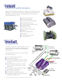
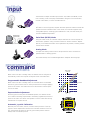
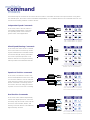
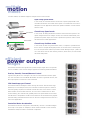
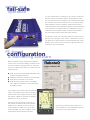
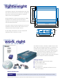
AX2550
Dual Channel,
Forward/Reverse
Digital Speed Controller
2 x 120 SmartAmps
for Remote Controlled and
Computer Guided Robotic Vehicles
oboteq’s AX2550 controller is designed to convert commands received from a R/C radio,
Analog Joystick, wireless modem, or microcomputer
into high voltage and high current output for driving
one or two DC motors. Designed for maximal easeof-use by professional and hobbyists alike, it is delivered with all necessary cables and hardware and is
ready to use in minutes.
Key Features
Benefits
Microcomputer-based
digital design
Accurate, reliable, and fully programmable operation
R/C mode support
Connects directly to simple, low cost
R/C radios
Serial mode support
Connects directly to microcomputers for
autonomous operation or to wireless
modem for two-way remote control
The controller's two channels can either be operated
independently or mixed to set the direction and rotation of a vehicle by coordinating the motion on each
side of the vehicle. The motors may be operated in
open or closed loop speed mode. Using low-cost
position sensors, they may also be set to operate as
heavy-duty position servos.
Analog mode support
Connects directly to analog joystick
Built-in power drivers for
two motors
Supports all common robot drive
methods
Up to 120A output per
channel
Gives robot strongest lifting or pushing
power
Smart automatic current
limitation
Protects motors, wiring and battery.
High reliability
The AX2550 can be reprogrammed in the field with
the latest features by downloading new operating
software from Roboteq’s web site. Numerous safety
features are incorporated into the controller to
ensure reliable and safe operation in the most
demanding mobile robotic vehicle applications.
Open loop or closed loop
speed control
Low cost or higher accuracy speed
control
Closed loop position
control
Create low cost, ultra-high torque jumbo
servos
Data Logging Output
Capture operating parameters in PC or
PDA for analysis
Built-in DC/DC converter
Operates from a single 12V-40V battery
Extruded aluminum, heat
sinking enclosure
Operates in the harshest shock and
temperature environment
Field upgradable
software
Never obsolete. Add features via the
internet
R
© copyright 2002-2003. Rev 1.3 August 25, 2003
give your
robot
muscle with brains
Roboteq’s AX2550 controller is designed to fit a wide range of mobile robotic vehicle
applications. Its compact size, high power drive capability, advanced safety features
and multiple command modes make it the preferred choice for autonomous or
remotely operated robots, such as:
● Automatic Guided Vehicles
● Law Enforcement Robots
● Hazardous Material Handling Robots
● Personal Transport Systems
● Underwater Remote Operated Vehicle
● Surveillance Robots
● Telepresence systems
● Bomb and Mine Removal robots
● Battlebots
● Remote Exploration Robots
● Animatronics
● Life-size model cars or boats
● ... and many others
easy to
install
anywhere
The AX2550 is designed for simple installation in a variety
of robotic vehicles. The controller is fitted with heavy
gauge cables for direct connection to high amperage batteries and motors.
Optional Speed
or Position Sensors
DC Motors
Up to 5HP on each
channel
A convenient 15-pin connector is used for the following
low voltage connections:
● 2 or 3* channel radio receiver inputs
● RS232 communication port
● Analog inputs for applying commands, or connecting to optional speed, position or motor temperature sensors
● Input for Emergency Stop switch or “inverted”
switch for detecting when the robot is turned
upside-down
to Optional
● a 2A solid-state switched output for controlling a
Motor
Temperature
brake, weapon or other accessory.
Sensors
● one low-current on-off output
● two digital input for user-defined sensors
● a regulated 5V supply output for powering the R/C
24V, 2A
switched
radio (Battery Eliminator Circuit).
output
*3rd R/C channel is needed to activate accessory/weapon outputs in R/C mode
Optional 12V Supply
for Controller Electronics
12 to 40V
Battery Power Supply
tes
eR
teS
R/C Receiver,
Wireless Modem,
or Microcomputer
low-level
digital
output
2 digital
inputs
Emergency Stop
or "Inverted" switch
multiple
input
modes
The AX2550’s multiple command input modes - R/C Radio Pulse Width, Serial
Port or Analog - make it uniquely interfaceable to all types of microcontrollers,
remote control radios, or other command devices.
tes
eR
teS
R/C Radio Mode
R/C Pulses
R/C Radio is the most popular, simplest and least expensive method to build and
operate a remote controlled robot. In this mode, the controller supports many
configurable options, including joystick calibration of min, max and center positions and deadband adjustment.
802.11 WLAN
or RF Modem
Serial Port (RS232) Mode
tes
eR
teS
Microcomputer
RS-232
Using the serial mode, the controller may be interfaced to a microcomputer for
autonomous operation. Using a wireless modem or wireless network adapter
(802.11), more advanced remote control operations are possible, including remote
control via the internet.
Analog Mode
A simple 0-5V analog control mode is also provided for direct connection to
potentiometers or analog joysticks.
tes
eR
teS
Analog
Visit www.roboteq.com for detailed applications examples and design tips.
programmable
command
corrections
Motor Output
(Forward)
logarithmic
When used in the R/C or Analog mode, the AX2550 can be configured to
automatically correct and compute an adjusted motor command value.
proportional
Programmable Deadband Adjustment
exponential
When used in the R/C or Analog mode, the controller allows a selectable
amount of joystick motion from its center position before it begins applying
power to the motors. This feature ensures a safe start and smooth operation for the robot.
Command
deadband
Exponentiation Adjustment
Motor Output
(R
)
After the joystick moves past the deadband position, the AX2550 can be
set to add an increasing (exponential) or decreasing (logarithmic) amount of
power to the motor. This allows the operator to set the robot’s best driving
characteristic for a particular use.
Automatic Joystick Calibration
With the push of a button, the min, max and center positions of the R/C
joysticks can be captured and stored in the controller. Because of this feature, the AX2550 will deliver on the full joystick travel position and will
always start at a safe idle position.
max
min
max
center
min
multiple
command
modes
The AX2550 may be connected to two motors which will react to commands received on two input channels. Using these
two channel inputs, the motors can be commanded independently or in a combined fashion to accommodate the most common drive and steering methods in robotic vehicles.
Independent Speed Commands
In this mode, each of the two motors is
commanded independently of the other.
This operating mode is best suited for
generic motor control applications.
Ch1 controls Motor 1’s speed
Ch2 controls Motor 2’s speed
Mixed Speed/Steering Commands
In this mode, the motors work in combination to move and turn a vehicle by combining the forward/reverse command information and the left/right steering information.
This mode of operation provides a cost
effective method for moving and steering
tank-style robots and underwater vehicles.
Ch1 and Ch2 are mixed to control
Motors 1 & 2 in coordination
Speed and Position commands
In this mode, one channel is used to control the forward/reverse motion of the vehicle. The other channel is used to make the
motor work like a position servo which can
be then connected to a steering column.
This mode is the most energy efficient as
no power is lost to friction due to skidding.
Ch1 controls Motor 1’s speed
Ch2 controls Motor 2’s position
Dual Position Commands
In this mode, each channel independently
controls the angular position of one motor.
The heavy duty servos built in this way can
be used to control throttle, brakes, and
steering of life-size vehicles or animate any
large and heavy structure.
Ch1 controls Motor 1’s position
Ch2 controls Motor 2’s position
multiple
motion
modes
For each channel, the AX2550 supports multiple motion control modes:
Open Loop Speed mode
In this mode, the controller delivers an amount of power proportional to the
command information. The actual motor speed is not measured. This mode is
adequate for most applications where the operator maintains a visual contact
with the robot.
Tachometer
Speed Feedback
Closed Loop Speed mode
In this mode, an analog tachometer measures the actual motor speed. If the
speed changes because of changes in load, the controller automatically compensates the power output. This mode is preferred in precision motor control
and autonomous robotic applications.
Position Feedback
Potentiometer
Closed Loop Position mode
In this mode, the axle of a geared down motor is coupled to a potentiometer
that is used to compare the angular position of the axle versus a desired position. This unique feature makes it possible to build ultra-high torque “jumbo servos” that can be used to drive steering columns, robotic arms, life-size models
and other heavy loads.
Gear box
efficient
power
stages
output
The AX-2550 includes two high-efficiency Power Output stages which can operate
from 12 to 40VDC. Each of these stages supports the following advanced features:
Precise, Smooth, Forward/Reverse Control
High efficiency MOSFET “H-Bridges” are used for full forward and reverse operation. The controller uses Pulse Width Modulation at 16kHz to generate smooth, variable output power in as little as 0.5% increments.
120 SmartAmps per Channel
The AX2550 features intelligent current sensing and control. After an initial surge
allowed up to over 200A per motor, the controller will limit the power to 120A for
the time typically required to accelerate or brake the robot. If the motor’s current
draw remains excessive after that time, as in the case of stalled motor or other
unusual loading, the controller will gradually reduce the power based on the measured MOSFET’s temperature. The MOSFET transistors are mounted directly against
the heat-sinking extruded aluminum case for efficient cooling without the need of a
fan in most applications.
Controlled Motor Acceleration
The AX2550 can also be configured to automatically “smooth” command changes
(from stop to full speed, for example) to avoid sudden overloads on the controller,
the batteries and/or the robot’s mechanical components.
simple and
fail-safe
operation
For all its sophistication, the AX2550 is very simple to install and
operate. Its many configuration options are programmed using
only two switches and a LED display on the controller front panel.
The controller may also be connected to a PC for setting configuration parameters using a convenient Graphical User Interface.
Once programmed, the configuration data are stored permanently
in the controller's non-volatile memory, eliminating the need for
cumbersome and unreliable jumpers. During normal operation,
the LED display provides running and alarm indication.
The AX2550 is fitted with many safety features ensuring a secure
power-on start, automatic stop in case of command loss, overcurrent protection on both channels, and overheat protection. A temperature sensor will shut down the power stage and protect the
controller in case of overheating.
PC-based
configuration
& monitoring software
While the AX2550 can be configured and operated
using it’s built-in switch and display, for added convenience the controller is delivered with a PC utility and
connection cable that will allow you to perform the following functions:
● Read and set the programmable parameters with a
user-friendly graphical inter-face
● Obtain the controller’s software revision and date
● Send precise commands to the motors
● Read and chart real-time current consumption
value, heatsink temperature, motor temperature
and battery voltage
For monitoring the controller while operating the
robot in its intended environment, the AX2550 is
delivered with a Data Logger software for Palm
Pilot® PDA’s, capable of recording 12 operating
parameters for up to 30 minutes.
Using the PC and an internet connection, it is
also possible to download and install software
updates to the controller in order to improve
existing features or enable new ones as they
become available. This unique capability keeps
the AX2550 from ever becoming obsolete.
Upon request, Roboteq will also perform custom modifications to the embedded software to
meet specific user’s requirements.
sturdy and
lightweight
construction
3.00" (76 mm)
4.00" (102 mm)
5.50" (140 mm)
The AX2550 is built into a extruded aluminum case which
also serves as a heat sink for its electronics. The large fin
area ensures sufficient heat dissipation for operation
without a fan in most applications.
0.25"
(6.3 mm)
Mounting brackets on each end are provided for durable
assembly of the controller onto any robot chassis.
Optional shock mount absorbers may be added for use in
the most brutal environment.
7.00" (178 mm)
The 15-pin connector includes mounting nuts to secure a
permanent connection with the radio receiver or microcomputer and the various external sensors.
At 2lbs (900g), the AX2550 is the most compact and
lightweight motor controller in its class.
8.00" (203 mm)
9.00" (228.5 mm)
1.60"
(40 mm)
Program Set
Reset
4.00" (102 mm)
5.50" (140 mm)
ready to
work
right
out of the box
The AX2550 controller is delivered complete with the hardware, cables, and software necessary for its operation. The
controller’s factory default settings will satisfy the most
common robot designs so that it can be installed and operated within minutes of unpacking. The controller is
supported by a detailed and illustrated User’s
Manual, including a 10-page Quick Start section and
over 150 pages of Reference Information.
Package Content
● AX2550 controller fitted with power cables
● R/C radio adapter cable
● Serial Communication cable
● Quickstart Manual
● CD containing PC Configuration Software, and complete User’s Manual.
Ordering References
AX2550
Dual Channel Forward/Reverse Speed controller up to 40V and 120A SmartAmps per channel
Partial references listing only. Order on-line at www.roboteq.com or from your local distributor
technical
specifications
Fully Digital, Microcomputer-based Design
Low Power Consumption
● Multiple operating modes
● Fully programmable using either built-in switches and 7 segment
LED display or through connection to a PC
● Non-volatile storage of user configurable settings. No jumpers
needed
● Simple operation
● Software upgradable with new features
● On board DC/DC converter for single 12 to 40V battery system
operation
● Optional 12V backup power input for powering safely the controller if the main motor batteries are discharged
● 200mA at 12V or 100mA at 24V idle current consumption
● Power Control wire for turning On or Off the controller from
external microcomputer or switch
● No consumption by output stage when motors stopped
● Regulated 5V output for powering R/C radio. Eliminates the need
for separate R/C battery.
Multiple Command Modes
● Radio-Control Pulse-Width input
● Serial port (RS-232) input
● 0-5V Analog Voltage input
Multiple Advanced Motor Control modes
●
●
●
●
●
Independent channel operation
Mixed control (sum and difference) for tank-like steering
Open Loop or Closed Loop Speed mode
Position control mode for building high power position servos
Modes can be set independently for each channel
High Efficiency Motor Power Outputs
●
●
●
●
●
Automatic Joystick Command Corrections
●
●
●
●
Joystick min, max and center calibration
Selectable deadband width
Selectable exponentiation factors for each joystick
3rd R/C channel input for accessory output activation
Special Function Inputs/Outputs
● 2 Analog inputs. Used as
▲ Tachometer inputs for closed loop speed control
▲ Potentiometer input for position (servo mode)
▲ External temperature sensor inputs
▲ User defined purpose (RS232 mode only)
● One Switch input configurable as
▲ Emergency stop command
▲ Reversing commands when running vehicle inverted
● Up to 2 general purpose outputs for accessories or weapon
▲ One 24V, 2A output
▲ One low-level digital output
● Up to 2 digital input signals
Built-in Sensors
● Voltage sensor for monitoring the main 12 to 40V battery
● Voltage monitoring of internal 12V
● Temperature sensors on heatsinks of each power stages
Advanced Data Logging Capabilities
● 12 internal parameters, including battery voltage, captured
R/C command, temperature and Amps accessible via
RS232 port
● Data may be logged in a PC, PDA or microcomputer
● Data Logging Software supplied for PC and Palm Pilot PDA
●
●
●
●
●
Two independent power output stages
Dual H bridge for full forward/reverse operation
Ultra-efficient 2.5 mOhm ON resistance MOSFETs
12 to 40 V operation
SmartAmps Automatic current limitation based on actually measured transistor temperature.
▲ 120A up to 15 seconds (per channel)
▲ 100A up to 30 seconds
▲ 80A extended
Longer high Amps operation with forced cooling
High current 8 AWG cable sets for each power stages
250A peak Amps per channel
16 kHz Pulse Width Modulation (PWM) output
Heat sink extruded case
Advanced Safety Features
● Safe power on mode
● Optical isolation on R/C control inputs
● Automatic Power stage off in case of electrically or software
induced program failure
● Overvoltage and Undervoltage protection
● Watchdog for automatic motor shutdown in case of command
loss (R/C and RS232 modes)
● Large and bright run/failure diagnostics on 7 segment LED display
● Programmable motors acceleration
● Built-in controller overheat sensors
● External motor temperature sensing and protection
● Emergency Stop input signal and button
Sturdy and Compact Mechanical Design
● All-in-one design. Built from aluminum heat sink extrusion with
mounting brackets
● Efficient heat sinking. Operates without a fan in most applications.
● 9” (228.5mm) L, 5.5” W (140mm), 1.8” (40mm) H
● -20o to +70o C operating environment
● 2 lbs (900g)
1601 E. Sharon Dr.
Phoenix, AZ 85022, USA
email: [email protected]
w w w. r o b o t e q . c o m
Made in USA