1
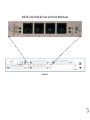
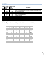
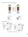
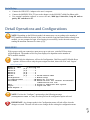
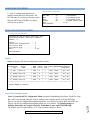
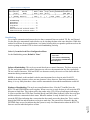
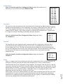
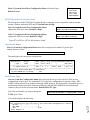
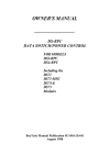
2012 DATA SWITCH DS74 COPYRIGHT 2012 Bay Technical Associates, Inc 12/1/2012 Table of Contents COMPLIANCE STANDARD .............................................................................................................................................................. 4 CONNECTION DESCRIPTION ........................................................................................................................................................... 5 INSTALLATION ............................................................................................................................................................................... 5 UNPACKING .................................................................................................................................................................................. 5 PREPARING THE INSTALLATION SITE ............................................................................................................................................................... 5 POWER .................................................................................................................................................................................................. 5 CABLING ........................................................................................................................................................................................ 7 RJ‐45 CABLE ............................................................................................................................................................................................. 7 SERIAL SETUP ................................................................................................................................................................................ 9 MAIN MENU .................................................................................................................................................................................. 9 CONFIGURATION MENU: ............................................................................................................................................................. 10 DS74 CONFIGURATION MENU: .................................................................................................................................................... 10 STATUS .................................................................................................................................................................................................. 10 SERIAL PORT CONFIGURATION .................................................................................................................................................................... 10 Handshaking ................................................................................................................................................................................... 11 Set Baud Rate ................................................................................................................................................................................. 12 Word Size ........................................................................................................................................................................................ 12 Stop Bits .......................................................................................................................................................................................... 12 Parity .............................................................................................................................................................................................. 12 RTS/DTR Line Driver Inactivity State ............................................................................................................................................... 13 PORT DEVICE NAME ................................................................................................................................................................................. 13 PORT DEVICE TYPE ................................................................................................................................................................................... 13 DS74 FUNCTIONAL TEST .............................................................................................................................................................. 14 DS74 RESET PROCEDURE ............................................................................................................................................................. 14 BAYTECH PRODUCT WARRANTY .................................................................................................................................................. 15 EXCEPTIONS ............................................................................................................................................................................................ 15 BAYTECH EXTENDED WARRANTY ................................................................................................................................................................ 15 TECHNICAL SUPPORT ................................................................................................................................................................................ 16 REPAIR POLICY......................................................................................................................................................................................... 16 RETURN AUTHORIZATION PROCESS: ............................................................................................................................................................. 17 Page 2 Serial 1: Port Pin out Table _____________________________________________________________________________________ 7 Serial 2: RJ08X007 Pin out _____________________________________________________________________________________ 8 Serial 3: RJ45 Receptacle & Plug ________________________________________________________________________________ 8 Serial 4: 9FRJ45PC‐1 Adapter Pin Out ____________________________________________________________________________ 8 Serial 5: 9FRJ45PC‐4 Adapter Pin out _____________________________________________________________________________ 8 Menu 1: Main Manu __________________________________________________________________________________________ 9 Menu 2: Module Configuration ________________________________________________________________________________ 10 Menu 3: DS74 Configuration __________________________________________________________________________________ 10 Menu 4: Serial Port Configuration ______________________________________________________________________________ 11 DS74 (4) EIA232 Serial Port Module Page 3 DS6 IPS ABOUT THIS DS74 OWNER’S MANUAL This document is applicable to the DS74 (4) EIA 232 Serial Port Module. This document provides information required for installing and operating your Bay Tech equipment. It should allow the user to connect to, power up, and access an applications menu where peripheral equipment can be controlled. We recommend reading this manual carefully, while placing special emphasis on correct cabling and configuration. If you have any problems with your installation, please contact a BayTech Applications Engineer at 228-563-7334, or toll free from anywhere in the United States using 1-800-523-2702 or contact us at our Web Site, www.baytech.net. BayTech manufactures many remote site management power products and data switches. If you would like information on any of these products, please contact BayTech Customer Service at the above numbers or visit our web site. Conventions used in this manual include: CAUTION: This term is used to denote any condition that could possibly result in physical harm to personnel or damage to equipment. IMPORTANT: This term is used to denote conditions that could result in the loss of communications or to highlight the proper functioning of equipment. NOTE: This term is used to denote items of interest to the user. <cr>: Carriage Return or ENTER The information in this document is subject to change without notice. The statements, configurations, technical data, and recommendations in this document are believed to be accurate and reliable, but are presented without express or implied warranty. Users must take full responsibility for their applications of any products specified in this document. The information in this document is proprietary to Bay Technical Associates, Inc. In the interest of improving internal design, operational function, and/or reliability, Bay Technical Associates, Inc reserves the right to make changes to the products described in this document without notice. Bay Technical Associates, Inc does not assume any liability that may occur due to the use or application of the product(s) or circuit layout(s) described herein. Page BayTech units are in accordance with the general requirements of Standard for Information Technology Equipment (ETL listed, conforms to ANSI/UL 60950-1 2nd Edition and CAN/CSA C22.2 No. 60950-00. CE conforms to IEC 60950.) Equipment installations are to be in accordance with the Canadian Electrical Code, Part I, CSA C22.1-02; General Requirements – Canadian Electrical, Part II, CSA C22.2 No 0-M91; the National Electrical Code, NFPA 70-2005; and the National Electrical Safety Code, NFPA, IEEE C2-2002. 4 COMPLIANCE STANDARD We welcome any comments you may have about our products, and we hope that you will continue to look to BayTech for your remote management needs. CONNECTION DESCRIPTION BayTech's DS74 serial module provides an interface to communicate to other devices with a serial console port. An RJ45–RJ45 cable or RJ45-RJ45 cable with RJ45–9 pin adapter is needed to connect to the devices. The DS74 is part of a Data Switch chassis and Host module systems. The DS74 ports are not standard pin outs. Baytech does have a few RJ45 cable or 9-pin adaptors available for purchase. Baytech can send a PDF document of the desired cable/adaptor or you may use the pin-out chart later in the manual to make you own cable/adaptor. CAUTION: All power should be removed from the BayTech unit prior to removing or installing cables and /or adapters. INSTALLATION Unpacking Compare the unit and serial number of the equipment you received to the packing slip located on the outside of the box. Inspect equipment carefully for damage that may have occurred in shipment. If there is damage to the equipment or if materials are missing, contact BayTech Customer Support at 228-563-7334 or call toll free inside the United States at 800-523-2702. At a minimum, you should receive the following: 1. The DS Chassis, DS71-MD4 Host Module and DS74 Modules. 2. Manual insert describing the location of the User’s Guide on BayTech’s website at www.baytech.net. 3. 1 ea. DE-9 (9 pin) PC com port adapter, 9FRJ45PC-1. 4. 1 ea. RJ-45 Roll over cable, RJ08X007 and RJ04X007. NOTE: Keep the shipping container and packing material in the event future shipment is required. Preparing the Installation Site The installation area should be clean and free of extreme temperatures and humidity. Allow sufficient space behind the DS unit for cabling and receptacle connections. Access to installation site should be restricted to authorized personnel. Installation of these units should be limited to ITE and Telco server environments. PRÉPARATION DE L'EMPLACEMENT D'INSTALLATION Le secteur d'installation devrait être propre et exempt des températures et de l'humidité extrêmes. Permettez le suffisamment d'espace derrière l'unité de DS pour des raccordements de câblage et de réceptacle. L'accès à l'emplacement d'installation devrait être limité au personnel autorisé. L'installation de ces unités devrait être limitée à ITE et à environnements de serveur de Telco. 208V VAC Model: Internal 208 VAC 50/60 Hz, 10 Amps Maximum Load. 120V VAC Model: Internal 120 VAC 50/60 Hz, 15, Amps Maximum Load. Page 5 POWER CAUTION: This unit is intended for indoor use only. Do not install near water or expose this unit to moisture. To prevent heat buildup, do not coil the power cord when in use. Do not use extension cords. Do not attempt to make any internal changes to the power source. Do not attempt to modify any portion or component of DS Series Unit unless specifically directed to by BayTech personnel. BayTech must perform any internal operations. ATTENTION: Cette unité est prévue pour l'usage d'intérieur seulement. N'installez pas près de l'eau ou n'exposez pas cette unité à l'humidité. Pour empêcher l'habillage de la chaleur, ne lovez pas le cordon de secteur en service. N'employez pas les cordes de prolongation. N'essayez pas de n'apporter aucune modification interne à la source d'énergie. N'essayez pas de ne modifier aucune partie ou composant d'une unité de série DS à moins qu'ait spécifiquement dirigé vers par le personnel de BayTech. BayTech doit effectuer toutes les opérations internes. CAUTION: High-voltage surges and spikes can damage this equipment. To protect from such power surges and spikes, this unit must have a good earth ground or good power surge protection. ATTENTION: Les montées subites et les transitoires à haute tension peuvent endommager cet équipement. Pour se protéger contre de telles montées subites et transitoires de puissance, cette unité doit avoir une bonne protection rectifiée ou bonne de la terre de puissance de montée subite. Page 6 CAUTION: For PERMANENTLY CONNECTED EQUIPMENT, a readily accessible disconnect device (Circuit Breaker rated not to exceed the amperage rating of the unit) shall be incorporated in the fixed wiring between the power source and the Baytech unit. For PLUGGABLE EQUIPMENT, the socket-outlet shall be installed near the equipment and easily accessible. The outlets providing power to the unit shall be protected against over current, short circuit and earth fault by suitable rated protective devices. ATTENTION: Pour l'ÉQUIPEMENT DE MANIÈRE PERMANENTE RELIÉ, un dispositif aisément accessible de débranchement (disjoncteur évalué pour ne pas dépasser l'estimation d'ampérage de l'unité) sera incorporé dans le câblage fixe entre la source d'énergie et l'unité de Baytech. Pour l'ÉQUIPEMENT QUE L'ON PEUT BRANCHER, la douille-sortie sera installée près de l'équipement et facilement accessible. Les sorties fournissant la puissance à l'unité seront protégées contre le courant, le court-circuit et le défaut de terre finis par les dispositifs protecteurs évalués appropriés. CABLING RJ45 Cable Control Module RJ-45 pin Signals EIA 232 Signal Pin Signal Direction 1 2 DTR GND Out 3 4 5 6 7 8 RTS TX RX DSR GND CTS Out Out In In In Description Handshake, Line Driver Inactive State = Low: -12V when port is selected unless programmed differently. Used as a handshake line to enable/disable the receiving of characters. Signal Ground Handshake, Line Driver Inactive State = Low: -12 V when port is selected unless programmed differently Transmit (Data Out) Receive (Data In) Handshake In. +12V when not used Signal Ground Used as a handshake line to enable/disable the receiving of characters. Adapter signals Listed are the pin specifications for the BayTech cable and adapters and the terminal COM ports: Serial 1: Port Pin out Table RS-232 Port (RPC) 1 2 3 4 5 N/C 7 8 9 COM Port DE-9 Pin 4 7 3 2 6 5 8 4 1 COM Port DB-25 Pin 20 1 5 2 3 6 7 4 8 22 Signal DSR GND CTS RXD TXD DTR GND RTS DCD DTR 7 DTR GND RTS TXD RXD DSR GND CTS DTR DCD RI RS-232 Port (DS) 1 2 3 4 5 6 7 8 Page Signal Sample: RJ08X007 Standard Rollover Cable – RJ45 to RJ45 Serial 2: RJ08X007 Pin out Serial 3: RJ45 Receptacle & Plug Sample 9-pin Adapters Serial 4: 9FRJ45PC-1 Adapter Pin Out Serial 5: 9FRJ45PC-4 Adapter Pin out Page 8 (Use with RJ08X007 Cable and B/C switch in “B”) Serial Setup Connect the 9FRJ45PC-4 adapter to the user’s computer Connect the MODULE EIA-232 port to the adapter via the RJ08X007 rolled flat ribbon cable. Use terminal emulation software to access the unit, 9600 bps, 8 data bits, 1stop bit and no parity, B/C switch set to ‘B’. Detail Operations and Configurations NOTE: Depending on the DS-Series model, the menus may vary according to the number of DS74 modules installed in the unit. If this is not an initial set-up and Password has already been enabled, you are prompted to login. After logging in successfully, invoke the main menu by sending the attention character five times (;;;;;). MAIN MENU With a proper serial port connection, upon power-up or unit reset, a similar DS host menu will be displayed. The number of devices ports displayed is dependent on the number of DS74 modules installed. NOTE: Only the Admin user will see the Configuration, Unit Reset, and I/O Module Reset options. All users will see only the ports assigned to them, alone with ‘Exit’ and ‘Logout’. Menu 1: Main Manu Module 2: admin on Host EIA-232 Device A (2,1).........1 Device B (2,2).........2 Device C (2,3).........3 Device D (2,4).........4 DS-RPC (5,1).........5 DS-RPC Chassis ONLY Configuration .................C Module setup I/O Modules Reset ............RM Reset all I/O ports Unit Reset ...................RU Resets DS-unit. All internal and external communications are lost Exit ..........................X Access to additional menu options Logout ........................T Logout the user Enter Request :c NOTE: If select the “Configure” option and get the following message (Configuration mode in use), the other port has the configuration option selected. Page 9 IMPORTANT: Any changes made in the Configuration menu will take effect when the changes are saved. The unit will ask to save changes before exiting the configuration menu. CONFIGURATION MENU: 1st level of configuration identifies all modules connected to the DS-chassis. The DS74 has the (4) serial ports, May have more than one DS74 listed. DS-RPC are chassis with (4) power outlets. Menu 2: Module Configuration Module Configuration DS71-MD4 (2)..........1 Host Module DS74 (3)..........2 I/O EIA232 ports DS74 (4)..........2 I/O EIA232 ports DS-RPC (5)..........3 DS-RPC Chassis ONLY Exit......................X, CR Enter Request : DS74 CONFIGURATION MENU: Menu 3: DS74 Configuration Copyright(C) Bay Technical Associates 2005 Data Switch Series - EIA-232 I/O Module Module 2 Status..........................1 Serial Port Configuration.......2 Port Device Name................3 Port Device Type................4 Exit............................X, CR Enter Request: Status Select 1), displays the current configuration of the module. +----+------+-----------------+------+------+------+------+---------+----+----+ |Port|Device| Device | Baud | Word | Stop |Parity|Handshake|LineDrive| | | Type | Name | Rate | Size | Bits | | |DTR |RTS | +----+------+-----------------+------+------+------+------+---------+----+----+ | 1 | RPC | Device A | 9600 | 8 | 1 | None | None | HI | HI | +----+------+-----------------+------+------+------+------+---------+----+----+ | 2 | RS232| Device B | 9600 | 8 | 1 | None | None | HI | HI | +----+------+-----------------+------+------+------+------+---------+----+----+ | 3 | RS232| Device C | 9600 | 8 | 1 | None | None | HI | HI | +----+------+-----------------+------+------+------+------+---------+----+----+ | 4 | RS232| Device D | 9600 | 8 | 1 | None | None | HI | HI | +----+------+-----------------+------+------+------+------+---------+----+----+ Strike ENTER to continue Enter Serial Port Number (? = Help, ENTER = Exit) :1 Page Select 2), from the DS74 Configuration Menu configures Handshaking, Baud Rate, Word Size, Stop Bits, and Parity. through either the serial or modem ports using the menus. RTS and DTR Line Drivers can only be configured through the phone line via a modem Xon/Xoff, RTS and DTR Line Drivers can only be configured through the phone line via a modem. The default settings are 9600bps, 8 data bits, one stop bit, no parity, Handshake is none, and RTS/DTR High. The module asks for a port number, (1-4). Type a number and press ‘Enter’: 10 Serial Port Configuration Menu 4: Serial Port Configuration +----+------+-----------------+------+------+------+------+---------+----+----+ |Port|Device| Device | Baud | Word | Stop |Parity|Handshake|LineDrive| | | Type | Name | Rate | Size | Bits | | |DTR |RTS | +----+------+-----------------+------+------+------+------+---------+----+----+ | 1 | RS232| Device A | 9600 | 8 | 1 | None | None | HI | HI | +----+------+-----------------+------+------+------+------+---------+----+----+ Handshaking......................1 Baud Rate........................2 Word Size........................3 Stop Bits........................4 Parity...........................5 RTS Line Driver Inactive State...6 DTR Line Driver Inactive State...7 Handshaking For a simple communication between devices three connected lines are needed: TX, Rx, and Ground. For the data to be transmitted, both sides have to be clocking the data at the same baud rate. While this method is sufficient for most applications, it is limited in being able to respond to problems such as the receiver getting overloaded. This is where serial handshaking can help. Select 1), from the Serial Port Configuration Menu for the Handshaking menu, Default is 'None' Select handshaking: 1 For None 2 For Software Handshaking 3 For Hardware Handshaking Enter Request : Software Handshaking: This style uses actual data bytes as control characters. The lines necessary are TX, Rx, and ground since the control characters are sent over the transmission line like regular data. The two control characters, XON and XOFF are characters sent by the receiver of the data to halt the transmitter during communication. NOTE: A drawback to this method is also the most important fact to keep in mind. In ASCII transmissions these character values are non-character values; however, data being transmitted via binary, it is very likely that these values could be transmitted as data and the transmission would fail. Page 11 Hardware Handshaking: This style uses actual hardware lines. Like the TX and Rx lines, the RTS/CTS and DTR/DSR lines work together. When a receiver is ready for data, it will assert the RTS (Request to Send) line. This is then read by the sender at the CTS (Clear to Send) input, indicating it is clear to send the data. DTR (Data Terminal Ready) and DSR (Data Set Ready) allow the serial port and the modem to communicate their status. When the modem is ready for data to be sent, it will assert the DTR line indicating that a connection has been made across the phone line. This is read in through the DSR line and the modem can begin to send data. The general rule of thumb is that the DTR/DSR lines are used to indicate that the system is ready for communication where the RTS/CTS lines are used for individual packets of data. Set Baud Rate Select 2), from the Serial Port Configuration Menu changes the transfer rate of Data bits per second for the serial port, Default is 9600 Word Size Select baud rate: 1 For 300 2 For 600 3 For 1200 4 For 2400 5 For 4800 6 For 9600 7 For 19200 8 For 38400 9 For 57.6K A For 76.8K B For 115.2K Enter Request : The word size is the measurement of the actual data bits in a transmission. Which setting you choose depends on what information you are transferring. For example, standard ASCII has values from 0 to 127 (7 bits). Extended ASCII uses 0 to 255 (8 bits). If the data being transferred is simple text (standard ASCII), sending 7 bits of data per packet is sufficient for communication. A packet refers to a single byte transfer, including start/stop bits, data bits, and parity. Select 3), from the Serial Port Configuration Menu changes the Word Size, Default is 8 Select word size: 1 For 5 2 For 6 3 For 7 4 For 8 Enter Request : Stop Bits The Stop Bits are used to signal the end of communication for a single packet. Since the data is clocked across the lines and each device has its own clock, it is possible for the two devices to become slightly out of sync. Therefore, the stop bits not only indicate the end of transmission but also give the computers some room for error in the clock speeds. The more bits that are used for stop bits, the greater the lenience in synchronizing the different clocks, but the slower the data transmission rate. Select 4), from the Serial Port Configuration Menu changes the Stop Bits, Default is 1 Select stop bits: 1 For 1 2 For 1.5 3 For 2 Enter Request : Page Parity is a simple form of error checking used in serial communication. For even and odd parity, the serial port will set the parity bit (the last bit after the data bits) to a value to ensure that the transmission has an even or odd number of logic high bits. For example, if the data was 011, then for even parity, the parity bit would be 0 to keep the number of logic high bits even. If the parity was odd, then the parity bit would be 1, resulting in 3 logic high bits. This allows the receiving device to know the state of a bit so as to enable the device to determine if noise is corrupting the data or if the transmitting and receiving devices' clocks are out of sync. With no parity selected, it's assumed that there are other forms of checking that will detect any errors in transmission. No parity also usually means that the parity bit can be used for data, speeding up transmission. In modem-to-modem communication, the type of parity is coordinated by the sending and receiving modems before the transmission takes place. 12 Parity Select 5), from the Serial Port Configuration Menu selects the Parity, Default is None Select parity: 1 For None 2 For Even 3 For Odd Enter Request : RTS/DTR Line Driver Inactivity State RTS (Request to Send)/ DTR (Data Terminal Ready) is normally used in conjunction with an external modem. With no modem the RTS and DTS default state is High. Select 6), from the Serial Port Configuration Menu changes the RTS driver state, Default is “High” RTS Line Driver Inactive State is: High High ? (Y/N, CR for no change): Select 7), from the Serial Port Configuration Menu changes the DTR driver state, Default is “High” DTR Line Driver Inactive State is: High High ? (Y/N, CR for no change): Type “Y” for YES or “N” for NO and press ‘Enter’. Port Device Name Select 3), from the Configuration Menu allows the serial port to be renamed. Type the port number and press ‘Enter’. Enter Serial Port Number (? = Help, ENTER = Exit) :1 The unit displays the current port configuration. +----+------+-----------------+------+------+------+------+---------+----+----+ |Port|Device| Device | Baud | Word | Stop |Parity|Handshake|LineDrive| | | Type | Name | Rate | Size | Bits | | |DTR |RTS | +----+------+-----------------+------+------+------+------+---------+----+----+ | 1 | RS232| Device A | 9600 | 8 | 1 | None | None | HI | HI | +----+------+-----------------+------+------+------+------+---------+----+----+ Enter Port Device Name (Max. 16 characters): or press ENTER for no change .....:test Port Device Type Select 4), from the Configuration Menu allows the port device type to be selected. There are two configurations of port types. The standard RS-232 is the basic configuration for transfer of data. RPCSNMP is allows the port to be monitored through SNMP protocol. The host module will poll the port at a predetermined time based on the firmware and displays the RPC/RPS SNMP ID data from the unit connect to the port on the host main menu. Default is RS-232 Type Select the port number you want to change the TYPE, press ’Enter’. Enter Serial Port Number (? = Help, ENTER = Exit) :1 Page Module 2, Port 1 device type: RS232 Note: Changing port type will force a unit reset when configuration is exited RS-232..........................1 RPC-SNMP........................2 Exit............................X,CR Enter Request :2 13 The module displays the following: Select 1, allows serial information to pass but prevents SNMP information from passing through. Select 2, enables the SNMP information to pass through along with serial data. Select either option. The module displays the DS74 Configuration menu. NOTE: Once you make a change to the port type, you have to back out of the Port Type menu and will be asked to ‘Accept changes’. If you type ‘Y’ for YES, the changes take effect immediately for the serial port. Type “Y” to accept changes and press ‘Enter’. The module will display changes accepted. Accept changes ? (Y/N) :y Changes accepted. NOTE: If no RPC/RPS with SNMP enabled device is connected to the port, the host module will wait approximately 40 seconds for the port to respond to its polling upon power up or host module unit reset and display the following: No communication with RPC at Module # Port # DS74 FUNCTIONAL TEST An extra rollover cables (pin out 1-8, 2-7, 3-6, 4-5, 5-4, 6-3, 7-2, 8-1) is needed for this test. 1. Set up the Host module with modem or Ethernet cables for normal operations. 2. Connect the rollover cable between two DS74 ports. 3. Create a Modem/Ethernet session. (i.e. Hyper-terminal) Type semi-colon 5-times (; ; ; ; ;) Select one of the connected ports. 4. Connect PC to the Host module serial port. Type semi-colon 5-times (; ; ; ; ;) and select the other connected ports. 5. In one of the active session, type several random characters. They should be seen in the other open session. 6. Make the other session active and type several random characters to see them echoed in the other session. 7. This verifies the Chassis, Host module, and the I/O port is working. If a DS74 module appears not to be working, move the module to a different slot and retest. DS74 RESET PROCEDURE 1. Perform a host module Factory Default reset procedure. DS74 configuration is stored on Host Module Page 14 2. Select the DS74 module in the Configuration Menu; select Serial Port Configuration; select each option and change to default setting, 9600bps, 8 data bits, no parity, one stop bit, RTS and DTR High. BAYTECH PRODUCT WARRANTY Bay Technical Associates (BayTech) warrants that its products will be free from defects in materials and workmanship under normal use for a period of two years from date of purchase (or from date of shipment from BayTech if proof of purchase is not provided). During this warranty period, BayTech shall, at its discretion, either repair or exchange any defective product at no charge for labor and materials, or refund the amount paid for the product, less shipping and handling charges. Any replacement and/or repaired products are warranted for the remainder of the original warranty. The customer is responsible for properly packaging the product and for shipping costs for returns. The customer is liable for loss or damage to the product during shipping, as well as any other fees or charges associated with transporting the product back to BayTech. BayTech will pay return costs for delivery within the Continental United States. All repair and return shipments must be approved by BayTech and must be accompanied by an RA (return authorization) number. Please refer to our Repair and Return Policy below. For the initial 30 days from the original date of shipment, any unopened product may be returned to BayTech, accompanied by an RA number. Full purchase price will be refunded, provided that the product is in excellent condition. A product may not be returned after 30 days from the original date of shipment unless approved by BayTech management. For additional information or more specific warranty issues, contact BayTech’s Technical Support or Customer Service Departments at (800) 523-2702 or (228) 563-7334. Exceptions This warranty does not cover misuse or minor imperfections that fall within design specifications or that do not materially alter functionality. BayTech does not warrant and is not responsible for damages incurred in shipping and handling or caused by disasters (such as fire, flood, wind, earthquake, lightning, power surges or water). The warranty will be voided regarding products that have been neglected, altered, abused, misused, or used for purposes other than those for which it was designed. Under no circumstances shall BayTech be liable for any special, incidental, or consequential damages based upon breach of warranty, breach of contract, negligence, strict liability, or any other legal theory. Such damages include (but are not limited to) loss of profits, loss of the product or associated equipment, cost of capital, cost of substitute or replacement equipment, facilities or services, down time, purchaser’s time, the claims of third parties, including customers, and injury to property. BayTech Extended Warranty Page 15 Extended warranties and but only at the time of product purchase. The extended warranty cost will not exceed 7% per year of the product list price unless otherwise stated in the customer contract or approved by BayTech management. Contact BayTech for further details on this. Technical Support BayTech offers Tech Support for the lifetime of the product. A staff of Applications Engineers is on duty to assist with installation, set up or operation issues. Support is available from 8:00 a.m. to 5 p.m. (CST or CDT), Monday through Friday at the phone numbers or website provided below. Please have the following information available to help the Applications Engineers answer questions efficiently: BayTech model type Unit serial number Firmware version (if accessible) A list of devices connected to the BayTech unit A general description of the application being used and the intended outcome Information about cables and adapters being used (type, length, place of purchase) The name of the software emulation program being used Printout of the configuration status (if possible) Bay Technical Associates, Inc. 5239 A Avenue Long Beach Industrial Park Long Beach, MS 39560 Telephone: 800-523-2702 or 228.563.7334 FAX: 228.563.7335 Email: [email protected] Website: www.baytech.net Repair Policy (Return policy refers to BayTech products purchased and returned for credit or repair.) A Return Authorization (RA) number must be obtained in all cases before returning the BayTech product. Have the serial number and reason for the return or description of the problem handy. Customers in the Continental U.S. can call 1-800-523-2702 or international customers can call 228.563.7334 to obtain an RA number. Before dismantling equipment or returning the unit for any reason, always contact BayTech. Attempting to repair a product without BayTech authorization may result in voiding the warranty. Cost and Time: The cost of repair for units no longer under warranty will be $50.00 per hour plus cost of materials and shipping. Typical turnaround times for repairs are 3 days for domestic requests and 5 days for international. Page 16 Follow the instructions below for repackaging and shipping. NOTE: Power should be disconnected from the power source before servicing or dismantling. Return Authorization Process: a. Contact BayTech via Phone, Fax, or Email to get a Return Authorization (RA) Number. IMPORTANT: BayTech will not accept any returns without an RA number. b. Package the unit carefully in its original packaging or similar packaging. The warranty does not cover damage sustained during shipment. Enclose a letter with name, address, RA number, daytime phone number and description of the problem. c. Mark the RA number clearly on the outside of the package. d. Ship the unit by insured, prepaid carrier to the following address: Page 17 Bay Technical Associates 5239 A Avenue Long Beach Industrial Park Long Beach, MS 39560 RA #: 140-xxxxx