1
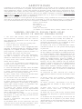
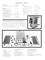
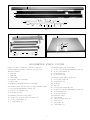
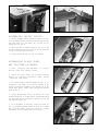
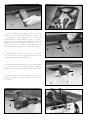
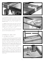
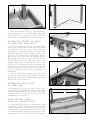
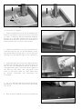
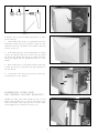
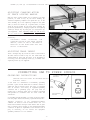
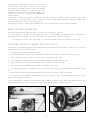
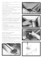
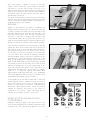
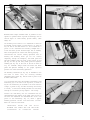
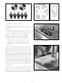
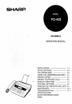
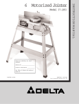
(Model 36-960)
D ATED 6-27-00
PA RT NO. 422-40-651-0003
Copyright ' 2000 Delta Machinery
INSTRUCTION M A N U A L
UNISAW fi
LeftTilt 10″ Tilting Arbor Saw
SAFETY RULES
W oodworking can be dangerous if safe and proper operating procedures are not followed. As with all machinery, there are certain
hazards involved with the operation of the product. Using the machine with respect and caution will considerably lessen the possibility of personal injury. However, if normal safety precautions are overlooked or ignored, personal injury to the operator may result.
Safety equipment such as guards, push sticks, hold-downs, featherboards, goggles, dust masks and hearing protection can reduce
your potential for injury. But even the best guard won t make up for poor judgment, carelessness or inattention. Always use common
sense and exercise caution in the workshop. If a procedure feels dangerous, don t try it. Figure out an alternative procedure that feels
safer. REMEMBER: Your personal safety is your responsibility.
This machine was designed for certain applications only. Delta Machinery strongly recommends that this machine not be modified
and/or used for any application other than that for which it was designed. If you have any questions relative to a particular application, DO NOT use the machine until you have first contacted Delta to determine if it can or should be performed on the product.
Technical Service Manager
Delta Machinery
4825 Highway 45 North
P. O. Box 2468
Jackson, TN 38302-2468
(IN CANADA: 505 SOUTHGATE DRIVE, GUELPH, ONTARIO N1H 6M7)
W ARNING: FAILURE TO FOLLOW THESE RULES
M AY RESULT IN SERIOUS PERSONAL INJURY
1. FOR YOUR OWN SAFETY, READ INSTRUCTION
M A N U A L BEFORE OPERATING THE TOOL. Learn the
tool s application and limitations as well as the specific
hazards peculiar to it.
2. K E E P GUARDS IN PLACE and in working order.
3. A LW AYS WEAR EYE PROTECTION.
4. GROUND ALL TOOLS. If tool is equipped with threeprong plug, it should be plugged into a three-hole electrical
receptacle. If an adapter is used to accommodate a twoprong receptacle, the adapter lug must be attached to a
known ground. Never remove the third prong.
5. REMOVE ADJUSTING KEYS AND WRENCHES.
Form habit of checking to see that keys and adjusting
wrenches are removed from tool before turning it on.
6. K E E P W O R K A R E A CLEAN. Cluttered areas and
benches invite accidents.
7. DON T USE IN DANGEROUS ENVIRONMENT.Don t
use power tools in damp or wet locations, or expose them
to rain. Keep work area well-lighted.
8. KEEP CHILDREN AND VISITORS AW AY.All children
and visitors should be kept a safe distance from work area.
9. M A K E W O R K S H O P CHILDPROOF with padlocks,
master switches, or by removing starter keys.
10. DON T FORCE TOOL. It will do the job better and be
safer at the rate for which it was designed.
11. USE RIGHT TOOL. Don t force tool or attachment to
do a job for which it was not designed.
12. WEAR PROPER A P PAREL. No loose clothing, gloves,
neckties, rings, bracelets, or other jewelry to get caught in
moving parts. Nonslip footwear is recom-mended. Wear
protective hair covering to contain long hair.
13. A LW AYS USE SAFETY GLASSES. W ear safety
glasses. Everyday eyeglasses only have impact resistant
lenses; they are not safety glasses. Also use face or dust
mask if cutting operation is dusty.
14. SECURE WORK. Use clamps or a vise to hold work
when practical. It s safer than using your hand and frees
both hands to operate tool.
15. DON T OVERREACH. Keep proper footing and
balance at all times.
16. MAINTAIN TOOLS IN TO P CONDITION. Keep tools
sharp and clean for best and safest performance. Follow
instructions for lubricating and changing accessories.
17. DISCONNECT TO O L S before servicing and when
changing accessories such as blades, bits, cutters, etc.
18. USE RECOMMENDED ACCESSORIES. The use of
accessories and attachments not recommended by Delta
may cause hazards or risk of injury to people.
19. REDUCE THE RISK OF UNINTENTIONAL STA R TING.Make sure switch is in OFF position before plugging
in power cord.
20. NEVER STAND ON TOOL. Serious injury could occur if
the tool is tipped or if the cutting tool is accidentally contacted.
21. CHECK DAMAGED PARTS. Before further use of the
tool, a guard or other part that is damaged should be carefully checked to determine that it will operate properly and
perform its intended function. Check for alignment of
moving parts, binding of moving parts, breakage of parts,
mounting, and any other conditions that may affect its
operation. A guard or other part that is damaged should be
properly repaired or replaced by an authorized service
center unless otherwise indicated elsewhere in this
instruction manual. Have defective switches replaced by
authorized service center. Do not use tool if switch does
not turn it on and off
.
22. DIRECTION OF FEED. Feed work into a blade or
cutter against the direction of rotation of the blade or cutter
only.
23. NEVER LEAVE TO O L RUNNING UNATTENDED.
TURN POWER OFF.Don t leave tool until it comes to a
complete stop.
24. DRUGS, ALCOHOL, MEDICATION. Do not operate
tool while under the influence of drugs, alcohol or any
medication.
25. MAKE SURE TO O L IS DISCONNECTED FROM
POWER SUPPLY while motor is being mounted,
connected or reconnected.
26. WHEN THE TO O L IS NOT IN USE, the switch should
be locked in the OFF position to prevent unauthorized use
of the tool.
27. W ARNING: The dust generated by certain woods and
wood products can be injurious to your health. Always
operate machinery in well ventilated areas and provide for
proper dust removal. Use wood dust collection systems
whenever possible.
2
ADDITIONAL SAFETY RULES FOR CIRCULAR SAW S
1. W ARNING: Do not operate your saw until it is completely assembled and installed according to the instructions.
2. IF YOU ARE NOT thoroughly familiar with the operation of circular saws, obtain advice from your supervisor,
instructor, or other qualified person.
3. A LW AY S use guard, splitter and anti-kickback fingers
on all thru-sawing operations. Thru-sawing operations
are those when the blade cuts completely through the
workpiece as in ripping or cross-cutting.
4. A LW AY S hold the work firmly against the miter gage
or fence.
5. N E V E R use the fence as a cut-off gage when crosscutting.
6. M O V E the rip fence out of the way when crosscutting.
7. N E V E R perform any operation free-hand which
means using your hands to support or guide the workpiece. Always use either the fence or miter gage to position and guide the work.
8. A LW AY S use a push stick for ripping narrow stock.
Refer to ripping applications in instruction manual where
the push stick is covered in detail.
9. AVOID kickbacks (work thrown back toward you) by:
A. Keeping blade sharp.
B. Keeping rip fence parallel to the saw blade.
C. Keeping splitter and anti-kickback fingers and
guard in place and operating.
D. Not releasing the work before it is pushed all the
way past the saw blade.
E. Not ripping work that is twisted or warped or does
not have a straight edge to guide along the fence.
10. AVOID awkward operations and hand positions
where a sudden slip could cause your hand to move into
the cutting tool.
11. A LW AY S keep hands and fingers away from the
blade.
12. N E V E R stand or have any part of your body in line
with the path of the saw blade.
13. N E V E R reach behind or over the cutting tool with
either hand for any reason.
14. DIRECTION OF FEED. Feed work into blade or cutter
against the direction or rotation of the blade or cutter only.
15. DO NOT feed the material too fast while cutting. Feed
the material only fast enough so that the blade will cut.
16. N E V E R attempt to free a stalled saw blade without
first turning the saw OFF.
17. N E V E R start the saw with the workpiece pressed
against the blade.
18. N E V E R turn the saw ON before clearing the table
of all objects (tools, scraps of wood, etc.).
19. A LW AYS STO P the saw before removing scrap
pieces from the table.
20. NEVER perform layout, assembly or set-up work on
the table while the saw is operating.
21. PROVIDE adequate support to the rear and sides of
the saw table for wide or long workpieces.
22. W H E N cutting mouldings, N E V E R run the stock between the fence and the moulding cutterhead.
23. N E V E R use solvents to clean plastic parts. Solvents
could possibly dissolve or otherwise damage the material.
Only a soft damp cloth should be used to clean plastic
parts.
24. S H O U L D any part of your circular saw be missing,
damaged, or fail in any way, or any electrical components
fail to perform properly, shut off switch and remove plug
from power supply outlet. Replace missing, damaged or
failed parts before resuming operation.
25. ADDITIONAL INFORMATION regarding the safe and
proper operation of this product is available from the
National Safety Council, 1121 Spring Lake Drive, Itasca,
IL 60143-3201, in the Accident Prevention Manual for
Industrial Operations and also in the Safety Data Sheets
provided by the NSC. Please also refer to the American
National Standards Institute ANSI 01.1 Safety Requirements for Woodworking Machinery and the U.S. Department of Labor OSHA 191 0.213 Regulations.
26. DUST CREATED BY POWER SANDING, SAW I N G,
AND OTHER CONSTRUCTION ACTIVITIES contains
chemicals from building materials that are known to cause
cancer, and birth defects or other reproductive harm.
Some examples of these chemicals are:
Lead from lead-based paints
Crystalline Silica from bricks and cement
Arsenic and Chromium from chemically-treated lumber
Your risk from these exposures varies, depending on how
often you do this type of work. To reduce your exposure to
these chemicals:
Use wet sanding methods.
Work in a well-ventilated area.
W ork with approved safety equipment. (Standard dust
masks DO NOT filter out the harmful microscopic
particles of these chemicals.)
S AVE THESE INSTRUCTIONS. Refer to them often and use them to instruct others.
FOREWORD
The Platinum Edition 10″ Unisaw is a very powerful machine. The motor is single phase, 3 horse power, 230 volt motor
that turns the circular blade at 4000 RPMs.
The Unisaw is a versatile machine, in that it can do precision ripping, cross-cutting, dadoing, moulding and tenoning.
3
MACHINE DATA
/8″ (16 mm)
10″ (254 mm)
4000 rpm
5
Diameter of Arbor
Diameter of Blade
Blade Speed (with 3450 rpm motor)
Capacities:
Maximum depth of cut
Maximum rip to right of blade
W ith Biesemeyer Commercial
Saw Fence System
Maximum rip to left of blade
W ith Biesemeyer Fence
Maximum thickness of cut at 45”
Distance; front of table to center of blade
Table in front of saw blade
At maximum depth of cut
Maximum width of dado
Table:
Height
Size with Extension Wing
And Biesemeyer Table Board
mm)
T-Slot Miter Gage Groove
Overall Dimensions:
Height
W idth with Wings and Guide Bar
W idth with Wing
And Biesemeyer 50″ Guide Bar
Depth
Depth with Biesemeyer Rip Fence
31/8″ (79 mm)
50″ (1270 mm)
12″ (305 mm)
21/8″ (54 mm)
1613/16″ (427 mm)
34″ (864 mm)
74″ x 27″ (1880x686
/8″ x 3/4″ (10x19 mm)
3
363/4″ (933 mm)
453/8″ (1152 mm)
84″ (2134 mm)
353/4″ (908 mm)
42″ (1067 mm)
121/4″ (311 mm)
/16″ (21 mm)
13
2
U N PACKING A N D CLEANING
Carefully unpack the saw and fence system from the shipping containers.
Clean all loose parts and remove the protective coating from the
machined surfaces of the saw table. This coating may be removed with a
soft cloth moistened with WD-40fi (do not use acetone, gasoline, or
lacquer thinner for this purpose). Figures 1, 2, 3, 4, and 5, illustrate the
saw and all loose items supplied with the machine.
1
Fig. 1
3
4
22
5
13
21
8
23
24 25
28
19
10
9
15
27
30
12
26
11
31
16
7 6 14
17
18
20
31
Fig. 2
1.
2.
3.
4.
5.
6.
7.
8.
9.
10.
11.
Unisaw
Switch
Motor cover
Blade guard and splitter bracket
Support rod
5/8″ Internal tooth washer
5/8-18 Jamb nut
Upper bracket for splitter
Lower bracket for support rod
5/16″ l.D. Flat washers (2)
5/16″ l.D. Lockwashers (3)
12.
13.
14.
15.
16.
17.
18.
19.
20.
21.
5/16
-18 x 1″ Hex head cap screws (4)
Arbor wrenches (2)
1/4″ and 3/8″ Hex wrenches
Miter gage
Flat washer for miter gage
Handle for miter gage handle
Cap for miter gage handle
Storage hook for arbor wrenches
#10 x 1/2″ hex washer head screws (10)
Hanger for miter gage
4
22.
23.
24.
25.
26.
27.
28.
29.
30.
31.
Hangers for rip fence (2)
Flat head screw for mounting switch
Flat washer for mounting switch
Hex nut for mounting switch
Gasket for motor cover
Cable tie
Latch for motor cover
Square cornered cast iron extension wing (right)
Square cornered cast iron extension wing (left
)
Mounting hardware
3
1
2
18
17
10
5
15
6
8
8
9
7 11
12
13
14
9
16
Fig. 3
24
4
19
25
28
23
27
26
21
22
23
20
21
22
23
Fig. 5
Fig. 4
BIESEMEYER FENCE SYSTEM
NOTE: A common hardware package is used for
several different models, therefore you may have
leftover hardware.
for fastening front rail to saw table
13 - 3/8-16 x 11/4″ long flat head Phillips screws (2)
14 - 7/8″ O.D. flat washers (2)
15 - Lock washers (2)
16 - 3/8-16 hex nuts (2)
1 - Rear Rail
2 - Front Rail
3 - Guide Tube
4- T-Squarefi Fence Assembly
5 - Cable Strap
6- Template for aligning front rail to saw table
for fastening guide tube to front rail
17 - 1/2 long hex screws (9)
18 - Lock washers (9)
for fastening front and rear rails to right extension table
7 - 11/2″ long flat head Phillips screws (12)
8 - 11/4″ O.D. Flat Washers (12)
9- 1/4-20 hex nuts (12)
leg hardware
19 - Legs (4)
20 - 5/8″ long wood screws #8 (16)
21 - 1/4-20 x 11/2″ long flat head phillips screws (8)
22 - 1/4″ flat washers (8)
23 - 1/4-20 hex nuts (8)
rear extension table
24 Table board
25 10-32 hex head screw (2)
26 10-32 nut (2)
27 Flat washer (4)
28 Lock washer (2)
for fastening rear rail to saw table
10 - 3/8-24 x 11/4″ long hex head cap screws (2)
11- 7/8″ O.D. flat washers (2)
12 - Lock washers (2)
5
A S S E M B LY
INSTRUCTIONS
E
W ARNING: FOR YOUR OWN SAFETY, DO NOT
CONNECT THE SAW TO THE POWER SOURCE
UNTIL THE SAW IS COMPLETELY A S S E M B L E D
AND YOU HAVE READ AND UNDERSTOOD THE
ENTIRE OWNER S MANUAL.
A
B
C
ASSEMBLING BLADE TILTING
MECHANISM HANDLE
Fig. 6
1. Install fiber washer (A) Fig. 6, on the blade tilting
mechanism shaft (B). Install key (C), into shaft keyway.
F
2. Install handwheel (D) onto shaft (B) Fig. 6. Make sure
the groove (E), in the handwheel lines up with the key (C).
3. Install lock knob (F) Fig. 7, into threaded end of the
shaft (B). Hand-tighten lock knob at this time.
B
Fig. 7
ASSEMBLING EXTENSION WINGS
A
Assemble the extension wings (A) Fig. 8 and Fig. 10, to
the saw table using the six 5/8″-24x 11/4″ hex head screws
(B) and washers supplied. Use a straight edge (C) Fig. 9,
to make sure the extension wings (A) are level with the
saw table before tightening the screws (B) Fig. 8 and Fig.
10. NOTE: When assembling the left extension wing,
do not install the left front screw and washer at this
time, it will be installed when assembling the on/off
switch.
B
Fig. 8
A
C
B
A
Fig. 10
Fig. 9
6
D
A
F
D
D
E
G
C
Fig. 12
Fig. 11
ASSEMBLING ON/OFF SWITCH
B
1. Loosely assemble switch and switch bracket (A) Fig.
12, to the inside front lip of the left extension wing with hex
flat head screw (D), flat washer (E), and hex nut (F)
through hole (G) Fig. 11.
2. Attach the side of switch bracket (A) Fig. 12, to the
inside of extension wing at the front of the saw using the
5/8″24x 11/4″ screw and flat washer.
3. Tighten screws (C) and (D), Fig. 12, securely.
A
ASSEMBLING BLADE GUARD
AND SPLITTER A S S E M B LY
1. MAKE CERTAIN THE MACHINE IS
NECTED FROM THE POWER SOURCE.
Fig. 13
A
DISCON-
2. Remove the table insert and saw blade from the
machine by following instructions under section
REMOVING SAW BLADE.
D
C
3. The inside splitter mounting bracket (A) Fig. 13, is
assembled to the inside of the saw and aligned at the
factory.To check the alignment of the bracket (A) to the
inside arbor flange, remove screw and splitter fastener
plate (B) Fig. 13.
Fig. 14
4. Using a straight edge (C) Fig. 14, check to see if the
splitter bracket (A) is aligned with the inside blade flange
(D). Check both the top and bottom of bracket (A) with top
and bottom of flange (D).
5. If an adjustment is necessary, loosen two screws (F)
Fig. 15, and adjust splitter bracket (A) until it is aligned
with the blade flange; tighten two screws (F). Loosely
reassemble screw and plate removed in STEP 3.
A
F
Fig. 15
7
H
G
J
Fig. 17
Fig. 16
6. Insert threaded end of support rod (G) Fig. 16,
through slot in back of saw and through hole (H) Fig. 16,
in rear trunnion. Fasten support rod (G) Fig. 16, to
trunnion using star washer and nut (J) Fig. 17. NOTE:
Thread nut (J) onto threaded end of support rod as far as
possible by hand. Using a wrench to hold nut (J) Fig. 17,
tighten rod (G) Fig. 18, using a small screwdriver (K) or
similar device through hole in end of rod (G) as shown.
G
K
7. Assemble lower bracket (L) Fig. 19, to rod (G) and
snug up with 2 one inch-long hex head screws (S) and
lockwashers, from underneath bracket (L).
Fig. 18
8. Assemble splitter bracket (M) Fig. 20, to lower bracket
(L), using one inch-long hex head screw (N), lockwasher
and flat washer. Do not fully tighten screw (N) at this time.
L
9. Fasten splitter and guard assembly (P) Fig. 21, to
bracket (M) using one inch-long hex head screw (V) and
flat washer.
S
G
Fig. 19
P
N
M
M
L
V
Fig. 20
Fig. 21
8
P
T
A
B
Fig. 23
Fig. 22
10. Assemble splitter (P) Fig. 22, inside the splitter
mounting bracket as shown. Push splitter (P) down as far
as possible, making certain bottom edge (T) of splitter (P)
is parallel with table surface, and tighten screw (B).
B
P
11. Reassemble the saw blade (U) Fig. 22.
N
12. Using a straight edge (A) Fig. 23, and square (B) Fig.
24, align splitter (P) with the saw blade and table by
moving brackets (M) and (L) until the splitter (P) is in
perfect alignment with the blade and square with the
table. After alignment is made, tighten hex head screw
(N), and two screws (S) Fig. 24.
L
M
S
Fig. 24
13. IMPORTANT: For certain cutting operations such as
dadoing and moulding where you are not cutting
completely through the workpiece, the blade guard and
splitter assembly cannot be used. Loosen screws (B) and
(V) Fig. 25. Lift up and swing blade guard and splitter
assembly to the rear of the saw.CAUTION: Always return
the blade guard and splitter assembly to its proper
operating position for normal thru-sawing operations.
V
B
BIESMEYER FENCE
A S S E M B LY
Fig. 25
ASSEMBLING GUIDE RAILS
1. Assemble the front rail (A) Fig. 26, to front of saw
table using the two 3/8-16 x 11/4″ flat head Phillips screws
(B), 7/8″ flat washers, lockwashers and 3/8-16 hex nuts
supplied. Screws (B) are inserted through the two holes in
the front rail, as shown in Fig. 26, and through the two
through holes in the front of the saw table and fastened to
the table with the flat washers, lockwashers and hex nuts.
IMPORTA N T: Do not completely tighten front rail
mounting hardware at this time.
A
B
Fig. 26
9
D
A
D
A
B
B
Fig. 28
Fig. 27
2. Using template (D) Figures 27 and 28, to check and
adjust front rail at both ends of the saw table as shown, to
make sure rail (A) is parallel with table surface and tighten
rail mounting hardware (B). IMPORTA N T: Template (D)
must be on the saw table when checking, not on
extension wing.
E
F
3. Assemble rear rail (E) Fig. 29, to rear of saw table
using the two 3/8-24 x 11/4″ hex head screws (F), 7/8″ O.D.
flat washers, and lockwashers as shown. NOTE: When
mounting, the two screws (F) are threaded into the
threaded holes in the saw table, as shown.
G
4. Make certain top edge of rail (E) Fig. 29 is below table
surface and that top edge of cut-outs (G) are below miter
gage slots before tightening screws (F).
Fig. 29
H
ASSEMBLING TABLE LEGS
TO EXTENSION TA B L E
1. Position the two legs (H) Fig. 30, at the two far corners
of the inside of one end of the extension table, as shown,
and mark the position of the eight holes to be drilled into
the bottom of the table. IMPORTA N T: If your saw will be
used with a mobile base underneath the saw base and
table legs, the position of the legs may have to be
changed to fit onto the mobile base. Remove the two
legs (H) and using a 1/16″ drill bit, drill the eight holes 1/2″
deep. Replace the two legs and fasten to the bottom of the
table using the eight 3/4″ wood screws (I) supplied.
I
Fig. 30
J
H
2. Figure 31 illustrates one of the legs (H) fastened to
the bottom of the extension table with the four wood
screws (I). Using a 1/4″ drill bit, drill two through holes
through the end piece (J) of the table, measuring the holes
from the outside frame of the table. The holes are to be
drilled 13/4″ from the top (laminate side), and 13/8″ and 4 3/8″
from the side.
I
M
Fig. 31
10
J
L
R
M
Fig. 32
Fig. 33
3. Fasten the leg bracket (L) Fig. 32, to the end piece (J)
of the table using the two 11/2″ flat head Phillips screws, flat
washers and hex nuts (M) Figs. 31 and 32. Fasten the
remaining leg to the extension table in the same manner.
P
N
ASSEMBLING EXTENSION TABLE
TO FRONT AND REAR RAILS
1. Place table assembly (N) Fig. 34, in position between
the two rails, as shown. Make sure end of table (N) is flush
against extension wing (P). Using a straight edge make
sure table (N) is in the same plane and level with saw table
(P). Lightly tap table up or down and adjust leveling screws
(R) Fig. 33, in bottom of legs to accomplish this. When the
table (N) Fig. 34 is level and in the same plane with saw
table (P), drill 1/4″ through holes (S) Fig. 34 through the
front and rear holes in the guide rail closest to the
extension wing. Fasten both front and rear rail to table
using the 11/2″ flat head Phillips screws, flat washers, and
hex nuts. Using a level make sure table (N) is in the same
plane and level with saw table (P). Drill 1/4″ through holes
(S) Fig. 34 through the front and rear holes remaining in
the guide rail.
2. After the holes have been drilled in the edge of the
front and rear extension table board, fasten both front and
rear rail to table using the 11/2″ flat head Phillips screws, flat
washers, and hex nuts (M) Fig. 31.
S
Fig. 34
B
A
D
D
ASSEMBLING GUIDE TUBE
TO FRONT RAIL
Fig. 35
Lay the guide tube (B) on the saw table as shown in Fig.
35, and line up the threaded holes on bottom of guide tube
(B) with the through holes (D) on the front rail (A). Fasten
the guide tube to the rail using 1/2″ hex screws and
lockwashers in all of the holes.
H
REAR SUPPORT TABLE
MOUNTING INSTRUCTIONS
I
1. Position the two legs (H) Fig. 36, at the two far corners
of the inside of one end of the extension table, as shown,
and mark the position of the eight holes to be drilled into
the bottom of the table. Remove the two legs (H) and using
a 1/16″ drill bit, drill the eight holes 1/2″ deep. Replace the two
legs and fasten to the bottom of the table using the eight
Fig. 36
11
J
H
J
L
I
M
M
Fig. 37
Fig. 38
/4″ wood screws (I) supplied.
3
2. Figure 37 illustrates one of the legs (H) fastened to the
bottom of the extension table with the four wood screws
(I). Using a 1/4″ drill bit, drill two through holes through the
end piece (J) of the table, measuring the holes from the
outside frame of the table. The holes are to be drilled 3/4″
from the bottom, and 11/4″ and 41/4″ from the side.
3. Fasten the leg bracket (L) Fig. 38, to the end piece (J)
of the table using the two 11/2″ flat head Phillips screws,
flat washers and hex nuts (M) Figs. 37 and 38. Fasten the
remaining leg to the extension table in the same manner.
Fig. 39
4. Position the table onto the rear rail, making sure there
is clearance for the miter gage slots and blade guard, and
mark the spots to be drilled in the rear rail to attach the
rear support table. NOTE: DRILL THE HOLES 1/4″ F R O M
THE EDGE OF THE RAIL, AND 71/2″ FROM EACH
EDGE OF THE REAR TABLE SO THAT THERE WILL
BE PROPER CLEARANCE FOR ATTACHING THE
H A R D WARE.
Fig. 40
5. Use a 3/16″ drill bit to drill the two holes in the rear rail,
approximately 71/2″ from each corner of the table board,
Fig. 39 & 40.
6. After the holes are drilled in the rear rail, position the
Fig. 41
12
Fig. 43
Fig. 42
table board back onto the rear rail, and drill through the
holes in the rear rail through the table board, Fig. 41.
P
7. Fasten the rear table board to the rear rail with two 1032 screws, lockwashers, flat washers, and nuts, Fig. 42.
8. Level the table by adjusting the table legs in the rear
table board, Fig. 43.
A
FASTENING MOTOR CORD
TO SAW FRAME
B
C
1. IMPORTA N T: Turn the blade tilting handwheel
counterclockwise as far as it will go until the saw blade is
in the 45 degree position.
2. IMPORTA N T: Turn the blade raising and lowering
handwheel counterclockwise as far as it will go.
3. Fasten motor cord (A) Fig. 44 to the saw frame cross
member (B), using the cable tie (C) supplied with the saw.
CAUTION: Before tightening the cable tie, make certain
that cord (A) is free of any interference from the motor or
saw blade at all possible positions of the motor.
After the cable tie is tightened, cut off excess tail of cable
tie (C) Fig. 44.
Fig. 44
A
C
A
B
A
Fig. 45
ASSEMBLING MOTOR COVER
1. Measure the three sides of the motor cover, (the sides
without the hinges), and cut gasket to fit each side.
Remove the protective paper from the gasket material
supplied with the machine and apply gasket (A) Fig. 45, to
three sides of the back of the motor cover (B). NOTE: Do
not apply gasket to the hinged side (C) of the motor cover
(B) Fig. 45.
C
D
B
2. Assemble hinged side (C) Fig. 46, of motor cover (B)
Fig. 46
13
G
F
B
E
E
J
B
H
Fig. 48
Fig. 47
to the left rear of the saw cabinet using three 1/2″ sheet
metal screws (D).
3. Insert locking lever (E) Fig. 47, through the hole in the
right edge of motor cover (B). Assemble spacer (F) over
threads of lever (E), and fasten lever to motor cover with
lock nut (G) Fig. 47.
E
B
4. W ith locking lever (E) in the raised position, as shown
in Fig. 48, swing the free end of motor cover (B) toward
the front of the cabinet until end (H) of locking lever fully
enters and engages with the pre-drilled hole (J) in the
cabinet.
Fig. 49
5. While holding motor cover against cabinet, push down
on lever (E) Fig. 49, to lock motor cover (B) in position on
the saw cabinet.
6. To open motor cover (B) Fig. 49, pull up on lever (E),
and swing motor cover outward.
A
B
ASSEMBLING MITER GAGE
AND WRENCH HOLDER BRACKETS
C
Fig. 50
Assemble the miter gage holder bracket (A) Fig. 50, and
wrench holder bracket (B) to the four thru-holes on the
front of the motor cover using the four 1/2″ sheet metal
screws supplied, two of which are shown at (C).
Fig. 51
14
C
B
A
Fig. 52
Fig. 53
B
Fig. 51, illustrates the miter gage and wrenches stored on
the two holder brackets.
A
ASSEMBLING RIP FENCE HOLDER
BRACKETS
Assemble the rip fence holder brackets (A) and (B) Fig.
52, to the four holes located in the right hand side of the
saw cabinet using four 1/2″ sheet metal screws supplied.
Figure 53 illustrates the Biesemeyer fence (C), (when not
in use), positioned on the two holder brackets.
Fig. 54
A
ATTACHING LITERATURE HOLDER
TO SAW CABINET
A literature holder (A) Fig. 54, is supplied with your saw to
provide storage and protection for the machine s
instruction manual, parts list, etc., so they may be readily
available for reference. Two push rivets (B) are supplied to
attach the literature holder to the right side of the saw
cabinet, as shown in Fig. 54.
B
Fig. 55
FENCE OPERATION
IMPORTA N T: Before operating fence, make
sure the fence is adjusted parallel to the miter
gage slot, as explained later on in this manual.
1. To place the fence on the guide rail, lift up clamp (A)
Fig. 55, and place the fence over the rail and gently push
fence onto rail (B) Fig. 55.
A
2. To move the fence along the guide rail, simply lift up
clamp lever (A) as shown in Fig. 55, slide fence to desired
position on rail, and push down on clamp lever (A) Fig. 56,
B
Fig. 56
15
to lock fence in position. NOTE: A magnet (B) Fig. 56, is
provided to hold clamp handle (A) in the up position when
moving the fence.
3. The distance the fence is positioned away from the
blade is indicated by the witness line (C) Fig. 57, located
on the cursor (D). If it is necessary to adjust the cursor (D),
make a test cut with the fence locked in position. Measure
the width of the finished cut and adjust the cursor (D) by
loosening the two screws (E), adjusting the cursor (D) until
the witness line (C) is aligned with the same marking on
the scale as the finished cut. Then tighten the two screws
(E).
C
D
E
Fig. 57
A
B
FENCE LUBRICATION
1. Apply paste wax to fence, and guide tube, sliding surfaces weekly.
2. Apply grease to cam lock (A) and cam foot (B) Fig. 58,
monthly, to prevent wear.
Fig. 58
ADJUSTING FENCE PARALLEL
TO MITER GAGE SLOTS
A
The fence (A) Fig. 59, must be adjusted so it is parallel to
the miter gage slots (B). To check and adjust, move fence
(A) until the bottom edge of the fence is in line with the
edge of one of the miter gage slots as shown in Fig. 59,
and push down on the fence clamping lever (C). Check to
see if the fence (A) is parallel to the miter gage slot, the
entire length of the table. If an adjustment must be made,
l
i
ft up fence locking lever (C) and raise fence up off the
guide tube, as shown in Fig. 60. Slightly tighten or loosen
one of the two adjusting screws (D) or (E) Fig. 60, using a
3/16″ alIen wrench (F), not supplied. Replace the fence on
the guide tube and check again to see if the edge of the
fence is parallel with the miter gage slot the entire length
of the slot. Repeat this adjustment until you are sure the
fence is parallel with the miter gage slot.
IMPORTA N T: VERY LITTLE MOVEMENT OF
B
C
Fig. 59
E
D
F
Fig. 60
16
SCREWS (D) AND (E) IS NECESSARY TO ADJUST THE FENCE PARALLEL WITH THE MITER GAGE SLOT.
B
ADJUSTING CLAMPING ACTION
OF FENCE LOCKING HANDLE
When the fence locking handle (A) is pushed to the down
position, as shown in Fig. 61, the fence assembly (B)
should be completely clamped to the guide tube (C). If the
fence assembly (B) is not completely clamped to the guide
tube (C) when the handle (A) is pushed down, as shown
in Fig. 61, lift up handle (A) and raise fence assembly (B)
up off the guide tube (C). Slightly tighten the two adjusting
screws (D) and (E) Fig. 60, using the 3/16″ allen wrench (F)
(not supplied). When adjusting screws (D) and (E) Fig.
60. the screws should be tightened to an equal amount.
Place fence on guide tube and recheck, adjust if
necessarry.
IMPORTA N T: AFTER
ADJUSTING
THE
CLAMPING ACTION OF THE FENCE LOCKING
HANDLE, CHECK TO SEE IF THE FENCE IS
PARALLEL TO THE MITER GAGE SLOT A N D
ADJUST IF NECESSARY.
A
C
Fig. 61
B
C
ADJUSTING TABLE INSERT
Place a straight edge (B) across the table at both ends of
the table insert as shown in Fig. 62. The table insert (A)
should always be level with the table. If an adjustment is
necessary, turn the adjusting screws (C), as needed. Four
adjusting screws (C) are supplied.
C
A
Fig. 62
CONNECTING SAW TO POWER SOURCE
GROUNDING INSTRUCTIONS
C U R R E N T C A R RYING
PRONGS
CAUTION: THIS TO O L MUST BE GROUNDED WHILE IN USE TO PROTECT THE OPERATOR FROM
ELECTRIC SHOCK.
In the event of a malfunction or breakdown, grounding
provides a path of least resistance for electric current to
reduce the risk of electric shock. The motor is equipped
with an electric cord having an equipment-grounding
conductor and a grounding plug. The plug must be
plugged into a matching outlet that is properly installed
and grounded in accordance with all local codes and
ordinances.
240
V O LT
GROUNDING
PRONG
Do not modify the plug provided - if it will not fit the outlet,
have the proper outlet installed by a qualified electrician.
Fig. 63
Improper connection of the equipment-grounding
conductor can result in risk of electric shock. The conductor with insulation having an outer surface that is green
with or without yellow stripes is the equipment-grounding
conductor. If repair or replacement of the electric cord or
plug is necessary, do not connect the equipment
grounding conductor to a live terminal.
17
Check with a qualified electrician or service personnel if the grounding instructions are not completely understood, or if in
doubt as to whether the tool is properly grounded.
Repair or replace damaged or worn cord immediately.
SINGLE PHASE OPERATION
THREE HORSEPOWER MOTO R S
The motor supplied with the Unisaw is single phase, 3 horsepower, and is designed to be operated from a 220-240 volt
power system only.
The single phase motor is intended to be used on a circuit that has an electrical outlet and plug that looks like the one
illustrated in Fig. 63. Make certain the tool is connected to an outlet having the same configuration as the plug (NEMA L15R). No adapter is available, or should be used with the tool. CAUTION: IN ALL CASES, MAKE CERTAIN THE
Total Length of
Gage of extension
RECEPTACLE IN QUESTION IS PROPERLY GROUNDED. IF YOU ARE NOT SURE, HAVE A CERTIFIED
cord in feet
cord to use
ELECTRICIAN CHECK THE RECEPTACLE.
50
14 AW G
If you desire to operate the tool with an extension cord, use a proper
extension cord and make certain it is in good condition. When using
100
12 AW G
an extension cord, be sure to use one heavy enough to carry the
Over 100
Not recommended
current your product will draw.An undersized cord will cause a drop
in line voltage resulting in loss of power and overheating. Fig. 64,
Fig. 64
shows the correct size to use depending on cord length and
nameplate ampere rating. If in doubt, use the next heavier gage. The
smaller the gage number, the heavier the cord.
O P E R ATING CONTROLS
AND ADJUSTMENTS
STARTING AND STOPPING THE SAW
1. To apply power to the machine, push ON button (A)
Fig. 65.
2. To stop the machine, push OFF button (B).
LOCKING SWITCH IN THE
A
OFF
B
Fig. 65
A
B
A
Fig. 66
D
POSITION
F
IMPORTA N T: When the tool is not in use the switch
should be locked in the OFF position using a padlock (A)
Fig. 66, to prevent unauthorized use of the tool.
BLADE RAISING MECHANISM
Fig. 67
The saw blade is raised and lowered with the front
handwheel (A) Fig. 67. With the exception of hollow
18
E
C
ground blades, the blade should be raised 1/8″ to 1/4″ above
the top surface of the material being cut. With hollow
ground blades, the blade should be raised the maximum
to provide greater clearance. To raise the saw blade,
loosen lock knob (B) Fig. 67, and turn the handwheel (A),
clockwise. To lower the saw blade, turn handwheel (A)
counterclockwise.
The saw blade is locked at any height by turning the lock knob (B) Fig. 67, clockwise. Due to the wedge action of this
locking device, only a small amount of force is required to lock the blade raising mechanism securely.Any added force
merely puts unnecessary strain on the locking device.
Limit stops for raising or lowering are permanently built into the mechanism and need no further adjustment.
BLADE TILTING MECHANISM
The blade tilting mechanism allows the blade to be tilted up to 45 degrees to the left
.
To tilt the saw blade to an angle, loosen lock knob (D) Fig. 67, and turn handwheel (C) until the pointer (F) indicates the
desired angle of tilt on scale (E). To lock the saw blade at the desired angle, tighten lock knob (D).
IMPORTA N T:A LW AYS LOCK THE BLADE IN POSITION BEFORE APPLYING POWER TO THE SAW .
ADJUSTING 90 AND 45 DEGREE POSITIVE STO P S
Positive stops are provided to quickly and accurately position the blade at 90 and 45 degrees to the table. To check and
adjust the positive stops, proceed as follows:
1. DISCONNECT S AW FROM POWER SOURCE.
2. Raise the saw blade all the way to the top and turn the blade tilting handwheel clockwise as far as it will go.
3. Using a combination square, check to see if the blade is 90 degrees to the table.
4. If an adjustment is necessary, turn the blade tilting handwheel counterclockwise one turn.
5. Loosen locknut (A) Fig. 68, and turn adjusting screw (B) counter clockwise, one turn.
6. Turn the blade tilting handwheel until the blade is 90 degrees to the table.
7. Turn adjusting head screw (B) clockwise, until it just contacts the casting on the front trunnion, then tighten locknut
(A).
8. Check to see if the tilt indicator pointer points to the zero mark on the scale. Adjust if necessary.
9. Turn the blade tilting handwheel counterclockwise as far as it will go. Using a combination square, check to see if the
blade is at 45 degrees to the table.
10. If an adjustment is necessary, turn the blade tilting handwheel clockwise one turn, until the adjusting screw (D) Fig.
69, and locknut (C) are in view, in the opening in the front of the saw cabinet, as shown in Fig. 69.
D
C
B
A
Fig. 69
Fig. 68
19
11. Loosen locknut (C), and turn adjusting screw (D)
counter clockwise, on turn.
12. Turn the blade tilting handwheel until the blade is 45
degrees to the table.
13. Turn adjusting head screw (D) clockwise, until it just
contacts the casting on the front trunnion, then tighten
locknut (C), until it is locked into place.
14. Check to see if the tilt indicator pointer points to the 45
degree mark on the scale. Adjust if necessary
ADJUSTING TA B L E
The saw table has been aligned at the factory so the miter
gage slots are parallel to the saw blade; however, it is
recommended to check the alignment before initial
operation as follows:
1. DISCONNECT THE MACHINE FROM THE POWER
SOURCE.
2. Place a combination square (A) Fig. 70, on the table
with one edge of the square in the miter gage slot, as
shown, and adjust the square so the rule just touches one
of the teeth on the saw blade at the forward position, as
shown in Fig. 70. Lock the square in this position.
3. Rotate the saw blade so that the same tooth you used
in STEP 2 is in the rear position, as shown in Fig. 71, and
check this distance. Both the front and rear measurements
should be identical.
4. If an adjustment is necessary, loosen the four screws
that hold the table to the saw cabinet.
5. Shiftthetable until a position is found which brings the
saw blade in the center of the table insert slot, and parallel
to the miter gage slot.
6. Tighten the four screws that were loosened in STEP 4.
Fig. 70
Fig. 71
A
MITER GAGE OPERATION
AND ADJUSTMENT
Insert the miter gage bar into the miter gage slot and
assemble the washer and lock handle (A) Fig. 72, to the
miter gage bar as shown.
The miter gage is equipped with adjustable index stops at
90 degrees and 45 degrees right and left. Adjustment to
the index stops can be made by tightening or loosening
the three adjusting screws (B) Fig. 73.
To rotate the miter gage, loosen lock knob (A) Fig. 73, and
move the body of the miter gage (C), to the desired angle.
A
Fig. 72
D
C
B
Fig. 73
Fig. 74
20
The miter gage body will stop at 90 degrees and 45 degrees both right and left. To rotate the miter gage body past these
points, the stop link (D) Fig. 73, must be moved up and out of the way.
The head of the miter gage pivots on a special tapered screw (G) Fig. 74, that fastens the head to the miter gage bar.If
the miter gage head does not pivot freely, or pivots too freely, it can be adjusted by loosening set screw (H) Fig. 74, and
turning the screw (G) in or out. Be certain to tighten screw (H) after adjustment is made.
MAINTENANCE
B
CHANGING THE SAW BLADE
1. MAKE CERTAIN THE MACHINE IS DISCONNECTED FROM THE POWER SOURCE.
2. NOTE: Two wrenches are supplied with the saw for
changing the saw blade; a box end wrench and open end
wrench.
3. Remove table insert and raise saw blade to its
maximum height.
4. Place the open end wrench (B) Fig. 75, on the flats of
the saw arbor to keep the arbor from turning, and using
wrench (A), turn the arbor nut (C) counterclockwise.
Remove arbor nut, blade flange and saw blade.
5. Assemble the new blade, making certain the teeth are
pointing down at the front of the saw table and assemble
outside blade flange and arbor nut. With wrench (B) Fig.
75, on the flats of the arbor to keep it from turning, tighten
arbor nut by turning wrench (A) clockwise.
6. Replace table insert.
NOTE: Use only 10″ saw blades with 5/8″ arbor holes,
rated for at least 3450 RPMs.
C
A
Fig. 75
D
E
REPLACING BELTS AND ADJUSTING
BELT TENSION
C
1. DISCONNECT THE MACHINE FROM THE POWER
SOURCE.
2. Remove the blade and table insert, (see the section
on CHANGING THE SAW BLADE).
3. Open motor cover door to gain access to the motor.
4. Place a block of wood (C) Fig. 76, between the motor
and saw cabinet as shown. NOTE: It may be necessary to
raise the saw arbor in order to insert the wooden block.
Lower the saw arbor until the motor contacts the wood.
5. Loosen bolt (D) Fig. 76, and continue to lower the saw
arbor until all tension is removed from the belts (E) Fig. 77
and tighten bolt (D) Fig. 76.
6. Raise the saw arbor slightly and remove the block of
wood (C) Fig. 76.
7. Lower the saw arbor. Remove the belts (E) Fig. 76,
one at a time from the motor pulley.
8. Remove the belts (E) Fig. 77, one at a time from the
arbor pulley (F).
9. Assemble the three new belts, one at a time in the
grooves of the arbor pulley (F) Fig. 77, and onto the motor
pulley.
10. When the new belts are assembled on the arbor
pulley (F) Fig. 77 and the motor pulley, loosen screw (D)
Fig. 76
E
F
Fig. 77
21
Fig. 76, and carefully let the motor rest on the belts.
11. Correct belt tension is when there is approximately 1/4″
deflection in the center span of the pulleys, using light
finger pressure. After tension is applied, tighten screw (D)
Fig. 76.
PROTECTING CAST IRON TABLE FROM RUST
To clean and protect cast iron tables from rust, you will need the following materials: A pushblock from a jointer, a sheet
of medium Scotch-Brite Blending Hand Pad, a can of WD-40fi, a can of degreaser, a can of TopCotefi Aerosol. Apply
the WD-40fi and polish the table surface with the Scotch-Brite pad using the pushblock as a holddown. Degrease the
table, then apply the TopCotefi .
O P E R ATION
Common sawing operations include ripping and crosscutting plus a few other standard operations of a fundamental
nature. As with all power tools, there is a certain amount of hazard involved with the operation and use of the tool. Using
the tool with the respect and caution demanded as far as
safety precautions are concerned, will considerably lessen
the possibility of personal injury. However, if normal safety
precautions are overlooked or completely ignored,
personal injury to the operator can result. The following
information describes the safe and proper method for
performing the most common sawing operations.
NOTE: THE USE OF ATTACHMENTS AND A C C E SSORIES NOT RECOMMENDED BY DELTA M AY
RESULT IN THE RISK OF INJURY TO PERSONS
AND/OR DAMAGE TO THE TOOL.
CROSS-CUTTING
Fig. 78
Cross-cutting requires the use of the miter gage to position and guide the work. Place the work against the miter
gage and advance both the gage and work toward the
saw blade, as shown in Fig. 78. The miter gage may be
used in either table slot. When bevel cutting (blade tilted),
use the right miter gage slot so that the blade tilts away
from the miter gage and your hands.
Start the cut slowly and hold the work firmly against the
miter gage and the table. One of the rules in running a saw
is that you never hang onto or touch a free piece of work.
Hold the supported piece, not the free piece that is cut off
.
The feed in cross-cutting continues until the work is cut in
two, and the miter gage and work are pulled back to the
starting point. Before pulling the work back, it is good
practice to give the work a little sideways shift to move the
work slightly away from the saw blade. Never pick up any
short length of free work from the table while the saw is
running. A smart operator never touches a cutoff piece
unless it is at least a foot long.
For added safety and convenience the miter gage can be
fitted with an auxiliary wood-facing (C), as shown in Fig.
79, that should be at least 1 inch higher than the maximum
depth of cut, and should extend out 12 inches or more to
one side or the other depending on which miter gage slot
is being used. This auxiliary wood-facing (C) can be
fastened to the front of the miter gage by using two wood
screws (A) Fig. 79, through the holes provided in the miter
gage body and into the wood-facing.
C
A
Fig. 79
B
W ARNING: NEVER USE THE FENCE AS A
C U T-OFF GAGE WHEN CROSS-CUTTING.
Fig. 80
22
When cross-cutting a number of pieces to the same
length, a block of wood (B), can be clamped to the fence
and used as a cut-off gage as shown in Fig. 80. It is
important that this block of wood always be positioned in
front of the saw blade as shown. Once the cut-off length is
determined, secure the fence and use the miter gage to
feed the work into the cut.
This block of wood allows the cut-off piece to move freely
along the table surface without binding between the fence
and the saw blade, thereby lessening the possibility of
kickback and injury to the operator.
A
RIPPING
Ripping is the operation of making a lengthwise cut
through a board, as shown in Fig. 81, and the rip fence (A)
is used to position and guide the work. One edge of the
work rides against the rip fence while the flat side of the
board rests on the table. Since the work is pushed along
the fence, it must have a straight edge and make solid
contact with the table. The saw guard must be used. The
guard has anti-kickback fingers to prevent kickback, and a
splitter to prevent the wood from closing behind the blade.
Fig. 81
Start the motor and advance the work holding it down and
against the fence. Never stand in the line of the saw cut
when ripping. Hold the work with both hands and push it
along the fence and into the saw blade as shown in Fig.
81. The work can then be fed through the saw blade with
one or two hands. After the work is beyond the saw blade
and anti-kickback fingers, the hand is removed from the
work. When this is done the work will either stay on the
table, tilt up slightly and be caught by the rear end of the
guard or slide offthetable to the floor.Alternately, the feed
can continue to the end of the table, after which the work
islifted and brought back along the outside edge of the
fence. The cut-off stock remains on the table and is not
touched with the hands until the saw blade is stopped,
unless it is a large piece allowing safe removal. When
ripping boards longer than three feet, it is recommended
that a work support be used at the rear of the saw to keep
the workpiece from falling off the saw table.
Fig. 82
If the ripped work is less than 4 inches wide, a push stick
should always be used to complete the feed, as shown in
Fig. 82. The push stick can easily be made from scrap
material as explained in the section CONSTRUCTING A
PUSH STICK. When ripping stock 2 inches or narrower,
assemble an auxiliary wood facing to the fence, as
explained in the section USING AUXILIARY W O O D
FACING ON RIP FENCE and use a push stick.
USING A C C E S S O RY MOULDING
CUTTERHEAD
Moulding is cutting a shape on the edge or face of the
work. Cutting mouldings with a moulding cutterhead in the
circular saw is a fast, safe and clean operation. The many
Fig. 83
23
W
G
H
Fig. 85
Fig. 84
different knife shapes available make it possible for the
operator to produce almost any kind of mouldings, such as
various styles of corner moulds, picture frames, table
edges, etc.
The moulding head consists of a cutterhead in which can
be mounted various shapes of steel knives, as shown in
Fig. 83. Each of the three knives in a set is fitted into a
groove in the cutterhead and securely clamped with a
screw.The knife grooves should be kept free of sawdust,
which would prevent the cutter from seating properly.
IMPORTA N T: For certain cutting operations such as
dadoing and moulding where you are not cutting
completely through the workpiece, the blade guard and
splitter assembly cannot be used. Loosen screws (G) and
(H) Fig. 84. Lift up and swing blade guard and splitter
assembly (W) Fig. 84, to the rear of the saw as shown in
Fig. 85. CAUTION: Always return and fasten the blade
guard and splitter assembly to its proper operating
position for normal thru-sawing operations.
Fig. 86
The moulding cutterhead (A) Fig. 86, is assembled to the
saw arbor as shown. Also, the accessory moulding
cutterhead table insert (B), must be used in place of the
standard table insert.
It is necessary when using the moulding cutterhead to add
wood-facing (C) to the face of the rip fence, as shown in
Fig. 87. The wood-facing is attached to the fence with two
clamps, as shown in Fig. 85. When attaching wood facing
to a fence, 3/4 inch stock is usually suitable for most work,
although an occasional job may require 1 inch facing.
C
Position the wood-facing over the cutterhead with the
cutterhead below the surface of the table. Turn the saw on
and raise the cutterhead. The cutterhead will cut its own
groove in the wood-facing. Fig. 87, shows a typical
moulding operation. NEVER USE MOULDING CUTTERHEAD IN A BEVEL POSITION.
Fig. 87
IMPORTA N T: NEVER RUN THE STO C K
BETWEEN THE FENCE AND THE MOULDING
CUTTERHEAD AS IRREGULAR SHAPED
24
Fig. 89
Fig. 88
Fig. 90
WOOD WILL CAUSE KICKBACK.
When moulding end grain, the miter gage is used. The
feed should be slowed up at the end of the cut to prevent
splintering.
E
In all cuts, attention should be given the grain, making the
cut in the same direction as the grain whenever possible.
A LW AYS INSTALL BLADE GUARD
AFTER OPERATION IS COMPETE.
USING A C C E S S O RY DADO HEAD
D
IMPORTA N T: THE BLADE GUARD A N D
SPLITTER A S S E M B LY CANNOT BE USED
WHEN DADOING OR MOULDING AND MUST
BE REMOVED OR SWUNG TO THE REAR OF
THE SAW .
Fig. 91
Dadoing is cutting a rabbet or wide groove into the work.
Most dado head sets are made up of two outside saws
and four or five inside cutters, as shown in Fig. 88. Various
combinations of saws and cutters are used to cut grooves
from 1/8″ to 13/16″ for use in shelving, making joints,
tenoning, grooving, etc. The cutters are heavily swaged
and must be arranged so that this heavy portion falls in the
gullets of the outside saws, as shown in Fig. 89. The saw
and cutter overlap is shown in Fig. 90, (A) being the
outside saw, (B) an inside cutter, and (C) a paper washer
or washers which can be used as needed to control the
exact width of groove. A 1/4″ groove is cut by using the two
outside saws. The teeth of the saws should be positioned
so that the raker on one saw is beside the cutting teeth on
the other saw.
The dado head set (D) Fig. 91, is assembled to the saw
arbor as shown. IMPORTANT: The blade guard and
splitter assembly cannot be used when dadoing and must
be removed or swung to the rear of the saw as explained
previously in this manual. Auxiliary jigs, fixtures, push
Fig. 92
25
B
A
A
Fig. 93
Fig. 94
sticks and feather boards should also be used. Also, the
accessory dado head table insert (E) Fig. 91, must be
used in place of the standard table insert.
Fig. 92, shows a typical dado operation using the miter
gage as a guide.
W ARNING: NEVER USE THE DADO HEAD IN
A BEVEL POSITION.
IMPORTANT:ALW AYS INSTALL BLADE GUARD
AFTER OPERATION IS COMPLETED.
USING AUXILIARY WOOD FACING
ON RIP FENCE
It is necessary when performing special operations such
as moulding to add wood facing (A) Fig. 93, to one or both
sides of the rip fence, as shown. The wood facing is
attached to the fence with two clamps (B). 3/4 inch stock is
suitable for most work although an occasional job may
require 1 inch facing.
C
C
B
A wood facing should be used when ripping thin material
Fig. 95
26
PARTS, SERVICE O R W A R R A N T Y ASSISTA N C E
All Delta Machines and accessories are manufactured to high quality standards and
are serviced by a network of Porter-Cable/Delta Factory Service Centers and Delta
Authorized Service Stations. To obtain additional information regarding your Delta
quality product or to obtain parts, service, warranty assistance, or the location of the
nearest service outlet, please call 1-888-848-5175.
Two Year Limited Warranty
Delta will repair or replace, at its expense and at its option, any Delta machine, machine part, or
machine accessory which in normal use has proven to be defective in workmanship or material,
provided that the customer notifies his supplying distributor of the alleged defect within two years from
the date of delivery to him, of the product and provides Delta Machinery with reasonable opportunity to
verify the defect by inspection. Delta Machinery may require that electric motors be returned prepaid to
the supplying distributor or authorized service center for inspection and repair or replacement. Delta
Machinery will not be responsible for any asserted defect which has resulted from misuse, abuse or
repair or alteration made or specifically authorized by anyone other than an authorized Delta service
facility or representative. Under no circumstances will Delta Machinery be liable for incidental or
consequential damages resulting from defective products. This warranty is Delta Machinery s sole
warranty and sets forth the customer s exclusive remedy, with respect to defective products; all other
warranties, express or implied, whether of merchantability, fitness for purpose, or otherwise, are
expressly disclaimed by Delta.
Printed in U.S.A.