1
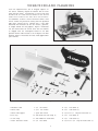
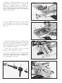
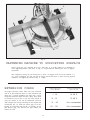
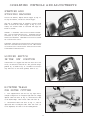
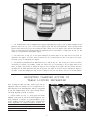
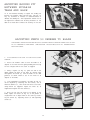
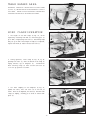
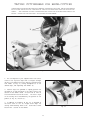
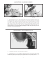
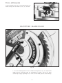
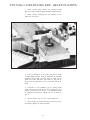
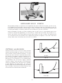
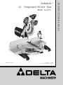
(Model 36-235)
REVISED 6-30-00
PA RT NO. 1349865
'Delta International Machinery Corp. 1999
INSTRUCTION M A N U A L
SidekickT M
12 Compound Miter Saw
TA B L E O F C O N T E N T S
SAFETY RULES ............................................................................... 3
ADDITIONAL SAFETY RULES F O R C O M P O U N D MITER S AW S ........................................ 4
U N PACKING A N D CLEANING .................................................................... 5
A S S E M B LY INSTRUCTIONS ..................................................................... 6
Moving Cuttinghead To The Up Position....................................................... 6
Moving Table To The 90 Degree Cut-Off Position ............................................... 6
Assembling Extension Table And Fence Slide .................................................. 7
Assembling W ork Clamp.................................................................... 9
Assembling Dust Bag ...................................................................... 9
FASTENING MACHINE TO SUPPORTING S U R FA C E ................................................ 10
EXTENSION C O R D S ........................................................................... 10
CONNECTING S AW TO P O W E R S O U R C E
Power Connections ....................................................................... 11
Motor Specifications ...................................................................... 11
Grounding Instructions .................................................................... 11
O P E R ATING C O N T R O L S A N D ADJUSTMENTS
Starting And Stopping Machine ............................................................. 12
Locking Switch In The OFF Position ....................................................... 12
Rotating Table For Miter Cutting ............................................................ 12
Adjusting Clamping Action Of Table Locking Mechanism ....................................... 13
Adjusting Sliding Fit Between Movable Table And Base......................................... 14
Adjusting Fence 90 Degrees To Blade........................................................ 14
Table Hazard Area ........................................................................ 15
W ork Clamp Operation .................................................................... 15
Tilting Cuttinghead For Bevel Cutting ........................................................ 16
Adjusting Sliding Fence ................................................................... 17
Adjusting Chip Deflector................................................................... 17
Adjusting 90 And 45 Degree Bevel Positive Stops.............................................. 18
Adjusting Sliding Fit Between Trunnion And Bevel Bracket...................................... 19
Adjusting Tension Of Cuttinghead Return Spring .............................................. 20
Adjusting Sliding Fit Between Cuttinghead Arm And Trunnion ................................... 20
Adjusting Downward Travel Of Saw Blade .................................................... 20
Tool Storage ............................................................................. 21
Adjusting Blade Guard .................................................................... 21
TYPICAL O P E R ATIONS A N D HELPFUL HINTS ..................................................... 22
Auxiliary Wood Fence ..................................................................... 23
Cutting Aluminum ........................................................................ 23
Cutting Bowed Material .................................................................... 24
Constructing Work Support Extensions ...................................................... 24
Cutting Crown Moulding ................................................................... 25
MAINTENANCE
Changing The Blade ...................................................................... 26
Brush Inspection And Replacement ......................................................... 27
W A R R A N T Y .................................................................................. 28
2
SAFETY RULES
W oodworking can be dangerous if safe and proper operating procedures are not followed. As with all machinery, there are certain
hazards involved with the operation of the product. Using the machine with respect and caution will considerably lessen the possibility of personal injury. However, if normal safety precautions are overlooked or ignored, personal injury to the operator may result.
Safety equipment such as guards, push sticks, hold-downs, featherboards, goggles, dust masks and hearing protection can reduce
your potential for injury.But even the best guard won t make up for poor judgment, carelessness or inattention. Always use common
sense and exercise caution in the workshop. If a procedure feels dangerous, don t try it. Figure out an alternative procedure that feels
safer. REMEMBER: Your personal safety is your responsibility.
This machine was designed for certain applications only. Delta Machinery strongly recommends that this machine not be modified
and/or used for any application other than that for which it was designed. If you have any questions relative to a particular application, DO N O T use the machine until you have first contacted Delta to determine if it can or should be performed on the product.
Technical Service Manager
Delta International Machinery Corp.
4825 Highway 45 North
P.O. Box 2468
Jackson, TN 38302-2468
(IN CANADA: 505 SOUTHGATE DRIVE, GUELPH, ONTARIO
N1H 6M7)
W ARNING: FAILURE TO F O L L O W THESE RULES
M AY RESULT IN SERIOUS P E R S O N A L INJURY
1. F O R Y O U R O W N SAFETY, READ INSTRUCTION M A N U A L
BEFORE O P E R ATING THE TO O L. Learn the tool s application and
limitations as well as the specific hazards peculiar to it.
2. KEEP G U A R D S IN PLACE and in working order.
3. A LW AY S W E A R EYE PROTECTION.
4. G R O U N D ALL TO O L S. If tool is equipped with three-prong
plug, it should be plugged into a three-hole electrical receptacle. f
I
an adapter is used to accommodate a two-prong receptacle, the
adapter lug must be attached to a known ground. Never remove the
third prong.
5. R E M O V E ADJUSTING KEYS A N D W R E N C H E S. Form habit
of checking to see that keys and adjusting wrenches are removed
from tool before turning it on.
6. KEEP W O R K A R E A CLEAN. Cluttered areas and benches
invite accidents.
7. DON T U S E IN D A N G E R O U S ENVIRONMENT. Don t use
power tools in damp or wet locations, or expose them to rain. Keep
work area well-lighted.
8. K E E P CHILDREN A N D VISITO R S AW AY. All children and
visitors should be kept a safe distance from work area.
9. M A K E W O R K S H O P CHILDPROOF with padlocks, master
switches, or by removing starter keys.
10. DON T FORCE TO O L. It will do the job better and be safer at
the rate for which it was designed.
11. U S E RIGHT TO O L. Don t force tool or attachment to do a job
for which it was not designed.
12. W E A R P R O P E R A P PAREL. No loose clothing, gloves, neckties, rings, bracelets, or other jewelry to get caught in moving parts.
Nonslip footwear is recommended. Wear protective hair covering to
contain long hair.
13. A LW AY S U S E SAFETY G L A S S E S.W ear safety glasses.
Everyday eyeglasses only have impact resistant lenses; they are not
safety glasses. Also use face or dust mask if cutting operation is dusty.
14. SECURE W O R K. Use clamps or a vise to hold work when
practical. It s safer than using your hand and frees both hands to
operate tool.
15. DON T O V E R R E A C H. Keep proper footing and balance at all
times.
16. MAINTAIN TO O L S IN TO P CONDITION. Keep tools sharp
and clean for best and safest performance. Follow instructions for
lubricating and changing accessories.
17. DISCONNECT TO O L S before servicing and when changing
accessories such as blades, bits, cutters, etc.
18. U S E R E C O M M E N D E D ACCESSORIES. The use of accessories and attachments not recommended by Delta may cause
hazards or risk of injury to persons.
19. R E D U C E THE RISK O F UNINTENTIONAL STARTING. Make
sure switch is in OFF position before plugging in power cord.
20. NEVER STA N D O N TO O L. Serious injury could occur if the
tool is tipped or if the cutting tool is accidentally contacted.
21. C H E C K D A M A G E D PARTS. Before further use of the tool, a
guard or other part that is damaged should be carefully checked to
ensure that it will operate properly and perform its intended function
check for alignment of moving parts, binding of moving parts,
breakage of parts, mounting, and any other conditions that may
affectits operation. A guard or other part that is damaged should be
properly repaired or replaced.
22. DIRECTION O F FEED. Feed work into a blade or cutter
against the direction of rotation of the blade or cutter only.
23. N E V E R L E AV E TO O L RUNNING UNATTENDED. TURN
P O W E R OFF. Don t leave tool until it comes to a complete stop.
24. DRUGS, ALCOHOL, MEDICATION. Do not operate tool while
under the influence of drugs, alcohol or any medication.
25. M A K E S U R E TO O L IS DISCONNECTED F R O M
POWER
SUPPLY while motor is being mounted, connected or reconnected.
26. W ARNING: The dust generated by certain woods and wood
products can be injurious to your health. Always operate machinery
in well ventilated areas and provide for proper dust removal. Use
wood dust collection systems whenever possible.
27. W ARNING: SOME DUST CREATED BY POWER SANDING,
S AWING, GRINDING, DRILLING,AND OTHER CONSTRUCTION
ACTIVITIES contains chemicals known to cause cancer, birth
defects or other reproductive harm. Some examples of these chemicals are: lead from lead-based paints; crystalline silica from bricks
and cement and other masonry products, and arsenic and chromium from chemically-treated lumber.Your risk from these exposures
varies, depending on how often you do this type of work. To reduce
your exposure to these chemicals: work in a well ventilated area,
and work with approved safety equipment, such as those dust
masks that are specially designed to filter out microscopic particles.
S AV E THESE INSTRUCTIONS.
3
ADDITIONAL SAFETY RULES F O R
C O M P O U N D MITER S AW S
1. W ARNING: U S E O N LY CROSS-CUTTING S AW
BLADES. D O N O T USE BLADES WITH D E E P G U LL E T S A S T H E Y C A N D E F L E C T A N D C O N TA C T
GUARD.
20. NEVER lock the switch in the ON position.
21. IMPORTA N T:After completing cut, release power
switch and wait for coasting blade to stop before returning saw to raised position.
2. W ARNING: Do not operate the miter saw until it is
completely assembled and installed according to the
instructions.
22. T U R N OFF S AW and M A K E S U R E blade has come
to a complete stop before removing or securing workpiece, changing workpiece angle or changing the angle
of the blade.
3. IF Y O U A R E N O T thoroughly familiar with the operation of compound miter saws, obtain advice from your
supervisor, instructor or other qualified person.
23. D O N O T remove jammed or cut-off pieces until
blade has stopped.
4. A LW AY S hold the work firmly against the fence and
table. D O N O T perform any operation freehand.
24. N E V E R cut ferrous metals or masonry.
25. NEVER recut small pieces.
5. W ARNING: A LW AY S keep hands out of path of saw
blade. If the workpiece you are cutting would cause your
hand to be inside the table hazard area (see section
TA B L E H A Z A R D AREA ), the workpiece should be
clamped in place before making cut.
26. PROVIDE adequate support to the sides of the saw
table for long workpieces.
27. N E V E R use the miter saw in an area with flammable
liquids or gases.
6. B E S U R E blade is sharp, runs freely and is free of
vibration.
28. N E V E R use solvents to clean plastic parts. Solvents
could possibly dissolve or otherwise damage the material.
Only a soft, damp cloth should be used to clean plastic
parts.
7. A L L O W the motor to come up to full speed before
starting cut.
8. K E E P motor air slots clean and free of chips.
29. DISCONNECT saw from power source before servicing or changing blades.
9. A LW AY S M A K E S U R E rotating table is tight before
cutting, even if the table is positioned in one of the
positive stops.
30. DISCONNECT saw from power source and clean
the machine before leaving it.
10. B E S U R E blade and flanges are clean and that arbor
screw is tightened securely.
31. M A K E S U R E the work area is cleaned before leaving
the machine.
11. U S E only blade flanges specified for your saw.
32. S H O U L D any part of your miter saw be missing,
damaged or fail in any way, or any electrical component
fail to perform properly, shut off switch and remove plug
from power supply outlet. Replace missing, damaged or
failed parts before resuming operation.
12. NEVER use blades larger or smaller in diameter than
recommended. Recommended size of blade is 12 in
diameter.
13. NEVER apply lubricants to the blade when it is running.
33. ADDITIONAL INFORMATION regarding the safe
and proper operation of this product is available from the
National Safety Council, 1121 Spring Lake Drive, Itasca,
IL 60143-3201, in the Accident Prevention Manual for
Industrial Operation and also in the Safety Data Sheets
provided by the NSC. Please also refer to the American
National Standard Institute ANSI 01.1 Safety Requirements for Woodworking Machinery and the U.S. Department of Labor OSHA 1910.213 Regulations.
14. A LW AY S check the blade for cracks or damage
before operation. Replace cracked or damaged blade
immediately.
15. N E V E R use blades recommended for operation at
less than 4800 RPM.
16. U S E the blade guard at all times.
17. A LW AY S keep the lower blade guard in place and
operating properly.
34. S AV E THESE INSTRUCTIONS. Refer to them frequently and use them to instruct others.
18. N E V E R reach around or behind saw blade.
19. M A K E S U R E blade is not contacting workpiece before switch is turned on.
4
U N PACKING A N D CLEANING
Your new compound miter saw is shipped complete in
one carton. Carefully unpack the machine and all loose
items from the carton. IMPORTA N T:D O N O T LIFT THE
MITER S AW B Y T H E S W I T C H H A N D L E O R TA B L E
C O N T R O L H A N D L E A S THIS M AY C A U S E MISALIGNMENT. A LW AY S LIFT T H E MACHINE B Y T H E
B A S E. Remove the protective coating from all unpainted
parts. This coating may be removed with a soft cloth
moistened with kerosene (do not use acetone, gasoline,
or lacquer thinner for this purpose). Figure 2 illustrates
the saw removed from the carton. Note that the machine
is shipped with the cuttinghead locked in the down
position and the table rotated to the 45 degree left miter
position. Figure 3 illustrates the loose items supplied with
your machine.
Fig. 2
4
2
1
5
6
3
7
9
16
8
17
18
13
14
15
12
11
10
Fig. 3
1 -Extension table
7 -1/8
hex wrench
2 -Fence slide
8 -5/32
3 -Fence slide support
9 -Open end wrench
hex wrench
13 -5/16
flat washer (2)
14 -5/16
lock washer (2)
15 -5/16-18 x 1/2
long hex head screw (2)
4 -Dust bag
10 -Lock knobs for work clamp (2)
16 -5/16
flat washer (2)
5 -W ork clamp
11 -Lock handle for slide fence
17 -5/16
lock washer (2)
6 -Arbor and fence wrench
12 -1/4
18 -5/16-18 x 1-1/4
flat washer
5
long hex head screws (2)
A S S E M B LY INSTRUCTIONS
W ARNING: F O R Y O U R O W N SAFETY, DO N O T C O N N E C T T H E MITER S AW TO T H E
P O W E R S O U R C E UNTIL T H E M A C H I N E IS C O M P L E T E LY A S S E M B L E D A N D Y O U
H AV E R E A D A N D U N D E R S TO O D THE ENTIRE O W N E R S MANUAL.
MOVING CUTTINGHEAD
TO THE UP POSITION
B
1. Pull out cuttinghead lockpin (A) Fig. 4, and move the
cuttinghead (B) to the up position.
A
Fig. 4
2. Fig. 5, illustrates the lockpin (A) pulled out and the
cuttinghead (B) in the up position.
B
A
Fig. 5
MOVING TABLE TO
THE 90 DEGREE
C U T-OFF POSITION
B
1. Depress table lock lever (A) Fig. 6, and rotatetable (B)
to the 90 degree straight cut-off position. Then release
lock lever (A).
A
Fig. 6
6
2. Fig. 7, illustrates the table (B) in the 90 degree
straight cut-off position. NOTE: Table lock lever (A) must
be depressed when rotating table. When lock lever (A) is
not depressed, the table is in the locked position and
cannot be moved.
B
3. For proper operation and adjustment of the table, refer
to sections, ROTATING TABLE F O R MITER CUTTING,
ADJUSTING CLAMPING ACTION O F TABLE LOCKING
MECHANISM and ADJUSTING SLIDING FIT B E T W E E N
M O VA B L E TA B L E A N D BASE.
A
Fig. 7
B
A
ASSEMBLING EXTENSION
TABLE AND FENCE SLIDE
Fig. 7A
B
1. Place 5/16 lockwasher and 5/16 flat washer on
each 1/2 long hex head screw (A) Fig. 7A, and thread
the two screws (A) into the two threaded holes on left
side of saw table, as shown. NOTE: Only thread the
screws a few threads into the holes at this time.
2. Assemble the table extension (B) Figs. 7A and 7B, to
left side of saw table making sure groove of table extension (B) is inside flat washers as shown in Fig. 7B.
3. Using a straight edge (C) Fig. 7C, make certain
extension table (B) is level with saw table (D) as shown,
and tighten the two screws (A) Fig. 7B.
A
Fig. 7B
C
D
B
Fig. 7C
7
4. Assemble the fence slide support (E) Fig. 7D, to the
extension table (B) using the two 1-1/4 long hex head
screws, 5/16 lockwashers and 5/16 flat washers (F).
Bring screws up through the two holes (G) in table extension and thread them into the two threaded holes (H) on
bottom of fence slide support. NOTE: Do not completely
tighten screws at this time.
E
H
H
G
F
B
Fig. 7D
5. Using a straight edge (C) Fig. 7E, make certain
fence slide support (E) is level with saw fence (J) as
shown, and tighten the two screws that were assembled
in STEP 4.
J
E
Fig. 7E
6. Position the fence slide (K) Fig. 7F, in position on top
of saw fence (J) and fence slide support (E). Slide fence
slide (K) back and forth several times to check alignment
of fence slide support (E) and make final adjustment to
fence slide support if necessary.
J
7. Remove screw and spring (L) Fig. 7G, and lock
handle (M) from locking stud (N) as shown.
K
E
8. Place 1/4 flat washer (O) Fig. 7G, onto locking stud
(N) and insert locking stud (N) Fig. 7H, through slot in
fence slide and thread locking stud into threaded hole in
fence slide support (E) as shown.
Fig. 7F
O
N
M
L
N
E
Fig. 7G
Fig. 7H
8
9. Position lock handle (M) Fig. 7J, on locking stud and
replace screw and spring (L) that were removed in STEP 7.
NOTE: Lock handle (M) is spring-loaded and can be repositioned by lifting up on handle and repositioning it on
stud located underneath handle.
M
L
Fig. 7J
ASSEMBLING WORK CLAMP
1. The standard equipment work clamp can be assembled
to any one of the three holes (A) Fig. 8, provided on the
base of the machine, as follows:
A
A
Fig. 8
2. Thread lock knob (B) Fig. 9, into threaded hole on
side of hole to be used and insert post (C) of work clamp
down through hole as far as possible. Then tighten lock
knob (B). An additional lock knob (B) is supplied and can
be threaded into one of the other three holes. We suggest
having the two lock knobs, one of which is shown at (B),
threaded into the two most commonly used holes where
the work clamp will be used.
3. For proper operation and adjustment of the work
clamp, refer to section W O R K C L A M P O P E R ATION .
C
B
Fig. 9
ASSEMBLING DUST BAG
A
B
1. Depress spring clips (A) Fig. 10, of dust bag (B) and clip
dust bag (B) onto end of dust chute, as shown.
Fig. 10
9
A
A
A
A
Fig. 11
FASTENING MACHINE TO SUPPORTING SURFA C E
Before operating your compound miter saw, make sure it is firmly mounted to a workbench or
other supporting surface. Four holes (A) Fig. 11, are provided for fastening the saw to a supporting surface.
When frequently moving the saw from place to place, we suggest that the saw be mounted to a
3/4 piece of plywood. The saw can then be easily moved from place to place and the plywood
clamped to the supporting surface using C clamps.
EXTENSION CORDS
Use proper extension cords. Make sure your extension
cord is in good condition and is a 3-wire extension cord
which has a 3-prong grounding type plug and a 3-pole
receptacle which will accept the tool s plug. When using
an extension cord, be sure to use one heavy enough to
carry the current of the saw. An undersized cord will
cause a drop in line voltage resulting in loss of power and
overheating. Fig. 12, shows the correct gage to use depending on cord length and voltage. If in doubt, use the
next heavier gage. The smaller the gage number, the
heavier the cord.
TO TA L LENGTH O F
C O R D IN FEET
G A G E O F EXTENSION
C O R D TO U S E
0 - 25
14 AW G
26 - 50
12 AW G
51 - 100
Not recommended
101 - 150
Not recommended
Fig. 12
10
CONNECTING S AW TO P O W E R S O U R C E
P O W E R CONNECTIONS
A separate electrical circuit should be used for your tools. This circuit should not be less than #12 wire and
should be protected with a 20 Amp time lag fuse. If an extension cord is used, use only 3-wire extension
cords which have 3-prong grounding type plugs and 3-pole receptacles which accept the tool s plug.
Before connecting the motor to the power line, make sure the switch is in the OFF position and be sure
that the electric current is of the same characteristics as indicated on the tool. All line connections should
make good contact. Running on low voltage will damage the motor.
M O TO R SPECIFICATIONS
Your saw is wired for 110-120 volts, 60 HZ alternating current. Before connecting the saw to the power
source, make sure the switch is in the OFF position. The motor provides a no-load speed of 3600 RPM.
G R O U N D I N G INSTRUCTIONS
CAUTION: THIS TO O L M U S T B E G R O U N D E D WHILE IN U S E
TO PROTECT THE O P E R ATO R F R O M ELECTRIC SHOCK.
Use only 3-wire extension cords that have 3-prong
grounding type plugs and 3-hole receptacles that accept
the tool s plug, as shown in Fig. 13.
In the event of a malfunction or breakdown, grounding
provides a path of least resistance for electric
current to reduce the risk of electric shock. The motor is
equipped with an electric cord having an equipmentgrounding conductor and a grounding plug. The plug
must be plugged into a matching outlet that is properly
installed and grounded in accordance with all local codes
and ordinances.
Repair or replace damaged or worn cord immediately.
This tool is intended for use on a circuit that has an outlet
and a plug that looks like the one shown in Fig. 13. A
temporary adapter, which looks like the adapter illustrated
in Fig. 14, may be used to connect this plug to a 2-pole
receptacle, as shown in Fig. 14, if a properly grounded
outlet is not available. The temporary adapter should be
used only until a properly grounded outlet can be installed by a qualified electrician. THIS ADAPTER IS
N O T APPLICABLE IN C A N A D A. The green-colored
rigid ear, lug, and the like, extending from the adapter
must be connected to a permanent ground, such as a
properly grounded outlet box, as shown in Fig. 14.
Do not modify the plug provided - if it will not fit the outlet,
have the proper outlet installed by a qualified electrician.
Improper connection of the equipment-grounding conductor can result in risk of electric shock. The conductor with
insulation having an outer surface that is green with or
without yellow stripes is the equipment-grounding conductor. If repair or replacement of the electric cord or plug is
necessary, do not connect the equipment grounding conductor to a live terminal.
Check with a qualified electrician or service personnel if
the grounding instructions are not completely understood, or if in doubt as to whether the tool is properly
grounded.
CAUTION: IN ALL CASES, MAKE C E R TAIN T H E RECEPTACLE IN QUESTION IS PROPERLY GROUNDED.
IF Y O U A R E N O T SURE, H AVE A CERTIFIED E L E CTRICIAN C H E C K THE RECEPTACLE.
GROUNDED OUTLET B O X
GROUNDED OUTLET B O X
CURRENT
C A R RYING
PRONGS
GROUNDING M E A N S
ADAPTER
GROUNDING BLADE
IS LONGEST O F THE 3 BLADES
Fig. 13
Fig. 14
11
O P E R ATING CONTROLS A N D ADJUSTMENTS
STARTING A N D
STOPPING MACHINE
To start the machine, depress switch trigger (A) Fig. 15.
To stop the machine, release the switch trigger.
This saw is equipped with an automatic electric blade
brake. As soon as the switch trigger (A) Fig. 15, is released, the electric brake is activated and stops the
blade in seconds.
A
DANGER: A TURNING SAW BLADE C A N B E DANGEROUS. AFTER COMPLETING C U T, RELEASE SWITCH
TRIGGER (A) FIG. 15, TO ACTIVATE B L A D E BRAKE.
KEEP CUTTINGHEAD DOWN UNTIL BLADE H A S C O M E
TO A C O M P L E T E STO P.
Fig. 15
W ARNING: THE TO R Q U E DEVELOPED DURING B R A KING M AY L O O S E N THE A R B O R S C R E W. THE A R B O R
S C R E W S H O U L D B E C H E C K E D PERIODICALLY A N D
TIGHTENED IF N E C E S S A RY.
LOCKING SWITCH
IN THE OFF POSITION
IMPORTA N T:W e suggest that when the miter saw is not
in use, the switch be locked in the OFF position using a
padlock (B), as shown in Fig. 16. Available as an accessory from Delta is the 50-325 padlock, shown at (B).
B
Fig. 16
R O TATING TABLE
FOR MITER CUTTING
1. Your compound miter saw will cut any angle from a
straight 90 degree cut to 47 degrees right and left. Simply
depress table lock lever (A) Fig. 17, and rotate the table
to the desired angle. Then release table lock lever (A).
2. IMPORTA N T:Table lock lever (A) Fig. 17, must be
depressed when rotating the table. When lock lever (A)
is not depressed, the table is in the locked position.
A
Fig. 17
12
C
D
E
B
Fig. 18
3. The compound miter saw is equipped with spring-loaded positive stops at the 90 degree straight cut-off
position and at the 15, 22.5, 31.62 and 45 degrees right and left miter positions. These spring-loaded
positive stops can be felt as you are rotating the table. NOTE: The 31.62 degree right and left miter positive
stops are used when cutting crown moulding as explained later in this manual. A large scale (B) Fig. 18, and
cursor (C) is provided for intermediate angles.
4. The center line (C) Fig. 18, on the cursor indicates the actual angle of cut. Each line on the scale (B)
represents one degree. In effect, when the center line (C) is moved from one line to the next on the scale,
the angle of cut is changed by one degree.
5. The pointer is provided with two additional lines (D) and (E) Fig. 18. This allows you to move the control
arm exactly 1/2 degree. For example, assume the center line (C) is pointing to the 10 degree mark on the
scale, as shown, and you want to change the angle of cut 1/2 degree to the right. Move the control arm until
the right line (E) lines up with the next line on the scale. The angle of cut will then be changed 1/2 degree to
the right. If you were changing the angle of cut 1/2 degree to the left, use the left line (D) in the same manner.
ADJUSTING CLAMPING ACTION OF
TABLE LOCKING MECHANISM
When rotating the table, the table locking lever must be
depressed. When the locking lever is not depressed, the
table should be in the locked position. Ifafter a long period
of time the clamping action of the table locking mechanism needs adjusted, proceed as follows:
1. Loosen locknut (A) Fig. 19, using open end wrench
supplied. Turn screw (B) with allen wrench supplied. Turn
screw clockwise to increase or counterclockwise to decrease clamping action of locking lever. IMPORTA N T:
After adjustment is completed tighten locknut (A),
just enough to take all play out of the handle assembly.
Tightening locknut (A) too much will defeat the
purpose of the adjustment.
B
A
Fig. 19
13
ADJUSTING SLIDING FIT
BETWEEN MOVABLE
TABLE AND BASE
If it ever becomes necessary to adjust the sliding fit
between the movable table and the base, turn nut (A)
Fig. 20, clockwise to increase or counterclockwise to
decrease the sliding fit. This adjustment should not be
too tight that it restricts the rotating movement of the
table or too loose that it affects the accuracy of the saw.
A
Fig. 20
ADJUSTING FENCE 90 DEGREES TO BLADE
IMPORTA N T:B E F O R E M A K I N G THIS A D J U S T M E N T M A K E C E R TAIN T H E B L A D E IS SET
AT 90 DEGREES TO THE TABLE. SEE SECTION ADJUSTING 90 A N D 45 DEGREE BEVEL
POSITIVE STOPS.
C
A
1. D I S C O N N E C T T H E S AW F R O M T H E P O W E R
SOURCE.
2. Rotate the movable table so that the blade is 90
degrees to the fence and the spring-loaded positive stop
for the 0 degree mark on the scale is engaged.
D
B
3. Using a square (A) Fig. 21, place one end of the
square against the front of the fence (B) and the other
end against the blade (C), with the blade in the down
position, as shown. Check to see if the fence is 90
degrees to the blade.
E
Fig. 21
4. If an adjustment is necessary, the fence (B) Fig. 21,
can be adjusted by loosening the four screws, two of
which are shown at (D), that attach the fence to the base,
using wrench (E) supplied. Adjust the fence (B) as
required and tighten the four screws (D).
F
5. After you are sure the fence is 90 degrees to the
blade, adjust the cursor (F) Fig. 22, so the pointer is
aligned with the 0 degree mark on the scale by loosening two screws (G), adjusting cursor (F) and tightening
screws (G).
G
Fig. 22
14
TABLE HAZARD A R E A
W ARNING: THE A R E A INSIDE THE T W O R E D LINES
(A) FIG. 23, ON THE TABLE IS DESIGNATED A S A HAZA R D ZONE. NEVER PLACE Y O U R H A N D S INSIDE THIS
A R E A WHILE THE TO O L IS BEING O P E R ATED.
A
A
Fig. 23
WORK CLAMP O P E R ATION
E
1. The height of the work clamp (A) Fig. 24, can be
adjusted by loosening lock knob (B) and moving post (C)
up or down, or depressing lock lever (D) and sliding clamp
body (E) up or down. After height of clamp (A) is adjusted,
tighten lock knob (B) and/or release lock lever (D).
D
A
B
C
Fig. 24
2. During operation, lower clamp (A) Fig. 25, by depressing lock lever (D), until the bottom of the clamp (A)
lightly contacts top of workpiece (F). IMPORTA N T:
When lowering clamp (A) make certain cam lever (G)
is in the up position as shown.
G
F
A
D
Fig. 25
3. For final clamping of the workpiece (F) Fig. 26,
against the table, move cam lever (G) to the rear, as
shown. After cut is completed, lift lever (G). This will raise
clamp (A) slightly, allowing you to slide or remove workpiece (F).
G
F
A
Fig. 26
15
TILTING CUTTINGHEAD FOR BEVEL CUTTING
IMPORTA N T:W H E N TILTING THE CUTTINGHEAD F O R BEVEL CUTTING, THE SLIDING FENCE
M U S T FIRST B E M O V E D TO T H E LEFT TO PROVIDE C L E A R A N C E F O R T H E B L A D E A N D
GUARD. THE D E G R E E O F TILT DETERMINES H O W FA R T H E SLIDING F E N C E M U S T B E
MOVED. REFER TO THE SECTION ADJUSTING SLIDING FENCE.
B
A
Fig. 27
1. The cuttinghead of your compound miter saw can be
tilted to cut any bevel angle from a 90 degree straight
cut-off to a 45 degree left bevel angle by loosening bevel
lock handle (A) Fig. 27, tilting cuttinghead (B) to the
desired angle, and tightening lock handle (A).
E
2. Positive stops are provided to rapidly position the
saw blade at 90 and 45 degrees to the table. Refer to the
section of this manual titled ADJUSTING 90 A N D 45
D E G R E E BEVEL POSITIVE STOPS. The bevel angle
of the cutting arm is determined by the position of the
pointer (C) Fig. 28, on scale (D).
D
C
3. In addition, an indicator (E) Fig. 28, is provided on
the bevel scale at the 33.9 degree bevel angle for
cutting crown moulding. Refer to the CUTTING C R O W N
MOULDING section of this manual.
Fig. 28
16
ADJUSTING SLIDING FENCE
A
B
A
Fig. 28A
Fig. 28B
1. The high sliding fence (A) Fig. 28A, provides support for extra large workpieces used with your
saw and should always be set as close as possible to the saw blade. When miter cutting (blade
set 90 degrees to the table and at an angle to the right or left), the fence should be set all the way
to the right, as shown in Fig. 28A. When bevel cutting, however (blade tilted at an angle to the
table), the fence (A) Fig. 28B, should be moved to the left to allow for proper clearance for the saw
blade and guard, as shown in Fig. 28B. This can be accomplished by loosening lock handle (B),
sliding the fence (A) to the desired location and tightening lock handle (B). NOTE: Lock handle (B)
is spring-loaded and can be repositioned by pulling up on handle and repositioning it on the
serrated nut located underneath handle.
ADJUSTING CHIP DEFLECTO R
A
B
Fig. 29
1. DISCONNECT THE S AW F R O M THE P O W E R SOURCE.
2. A chip deflector (A) Fig. 29, is supplied to help prevent scrap or cut-off pieces from entering
the upper blade guard. The chip deflector (A) should be adjusted so it is almost touching the side
of the blade by loosening screw (B), adjusting chip deflector (A) and tightening screw (B).
17
ADJUSTING
90 AND 45 DEGREE BEVEL
POSITIVE STO P S
1. D I S C O N N E C T T H E S AW F R O M T H E P O W E R
SOURCE.
2. Loosen bevel lock handle and move the cuttinghead
all the way to the right. Then tighten bevel lock handle
and lock cuttinghead in the down position.
A
3. Using a square (A) Fig. 30, place one end of the
square on the table and the other end against the blade,
as shown. Check to see if the blade is at 90 degrees to
the table.
Fig. 30
4. If an adjustment is necessary, loosen bevel lock
handle (H) Fig. 31. Then loosen locknut (B) and turn
adjusting screw (C), with wrenches provided, until blade
is 90 degrees to the table. Then tighten locknut (B) and
bevel lock handle (H).
H
5. When you are certain blade is 90 degrees to table,
adjust pointer to line up with the 0 degree mark on bevel
scale.
C
B
Fig. 31
6. Loosen bevel lock handle and move cuttinghead all
the way to the left bevel position and tighten bevel lock
handle.
7. Using a square (A) Fig. 32, check to see if the blade
is at 45 degrees to the table, as shown.
A
Fig. 32
8. If an adjustment is necessary, loosen bevel lock
handle. Then loosen locknut (E) Fig. 33, and turn adjusting screw (F), with wrenches provided, until blade is 45
degrees to the table. Then tighten locknut (E) and bevel
lock handle.
9. These positive stops enable you to rapidly position
the blade at the most common bevel angles to the table,
90 and 45 degrees.
F
E
Fig. 33
18
B
C
D
Fig. 36
ADJUSTING SLIDING FIT BETWEEN
TRUNNION AND BEVEL B R A C K E T
After a long period of time it may become necessary to
adjust the sliding fit between the trunnion (A) Fig. 36, and
the bevel bracket (B) by tightening adjusting nut (C)
using a 3/4 socket wrench.
NOTE: This adjustment must be made with the bevel
lock handle (D) loose.
Correct adjustment is when a good snug sliding fit is
obtained between these two parts. This adjustment should
not be too tight that it restricts the tilting movement of the
trunnion (A) when bevel cutting, or too loose that it affects
the accuracy of the saw cut.
19
A
B
C
D
A
Fig. 37
ADJUSTING TENSION OF
CUTTINGHEAD RETURN SPRING
The tension of the cuttinghead return spring has been adjusted at the factory in order that the cuttinghead returns to the up position after a cut has been made. If it ever becomes necessary to re-adjust the
spring tension, proceed as follows:
1. Turn adjusting screw (A) Fig. 37, clockwise to increase or counterclockwise to decrease the spring
tension.
ADJUSTING SLIDING FIT B E T W E E N
CUTTINGHEAD A R M A N D TRUNNION
After a long period of time it may become necessary to adjust the sliding fit between the cuttinghead
arm (B) Fig. 37, and the trunnion (C) by tightening nut (D). Correct adjustment is when a good snug
sliding fit is obtained between these two parts. This adjustment should not be too tight that it restricts
the sliding movement of the cuttinghead arm (B) or too loose that it affects the accuracy of the saw cut.
ADJUSTING DOWNWA R D
T R AVEL OF SAW BLADE
1. D I S C O N N E C T T H E S AW F R O M T H E P O W E R
SOURCE.
C
2. The downward travel of the saw blade can be limited
to prevent the saw blade from contacting any metal
surfaces of the machine. This adjustment is made by
loosening locknut (A) Fig. 38, and turning adjusting
screw (B) in or out until other end of screw (B) contacts
stop (C) at the full downward travel of the saw blade.
A
B
3. When making this adjustment, M A K E S U R E THE
M A C H I N E IS D I S C O N N E C T E D F R O M T H E P O W E R
S O U R C E and lower the blade as far as possible. Rotate
the blade by hand to make certain the teeth do not contact any metal surfaces and adjust if necessary.After
adjustment is completed, tighten locknut (A).
Fig. 38
20
TO O L STO R A G E
A clip is provided on the rear of the saw and provides a convenient storage area for wrench (A) Fig. 39, as shown.
A
Fig. 39
ADJUSTING BLADE G U A R D
A
B
Fig. 40
1. After an extended period of time the movable blade guard (A) Fig. 40, might become
sloppy and move erratically when the cuttinghead is lowered. This can be easily
corrected by slightly tightening nut (B) until the lower blade guard (A) moves smoothly.
21
TYPICAL O P E R ATIONS AND HELPFUL HINTS
1. Before cutting, make certain the cutting arm and
table are at their correct settings and firmly locked in place.
2. Before cutting, determine that the workpiece is the
right size for the saw.
A
Fig. 41
3. Place the workpiece on the table and hold or clamp
it firmly against the fence. Figure 41 illustrates the standard
equipment work clamp (A) being used to clamp a workpiece to the fence and table. The clamp (A) can also be
used in the rear position or on the left front side of the
blade.
4. W ARNING: If the workpiece you are cutting would
cause your hand to be inside the table hazard area (see
section TABLE H A Z A R D AREA ), the workpiece should
be clamped in place before making the cut, as shown in
Fig. 41.
5. For best results cut at a slow, even cutting rate.
6. Never attempt any freehand cutting (wood that is not
held firmly against the fence and table).
22
B
A
Fig. 43
AUXILIARY WOOD FENCE
When performing multiple or repetitive cut-off operations that result in small cut-off pieces, one inch or less,
it is possible for the saw blade to catch the cut-off pieces and project them out of the machine or into the
blade guard and housing, possibly causing damage or injury. In order to limit the possibility of personal injury
or blade guard damage, an auxiliary wood fence can be mounted to your saw as follows:
Holes are provided in the fence to attach an auxiliary fence (A) and (B) Fig. 43. This auxiliary fence is constructed of straight wood approximately 1/2 inch thick by 3 inches high by 20 inches long as shown at (B);
and 1/2 inch thick by 4-3/4 inches high by 20 inches long as shown at (A) Fig. 43. NOTE: The auxiliary fence
(A) is used O N LY with the saw blade in the 0 degree bevel position (90 degrees) to the table. When bevel
cutting (blade tilted) the auxiliary fence will have to be removed.
BLADE
CUTTING ALUMINUM
FENCE
Aluminum extrusions such as used for making aluminum
screens and storm windows can easily be cut with your
miter saw.When cutting aluminum extrusions, or other
sections that can be cut with a saw blade and are within
the capacity of the machine, position the material so the
blade is cutting through the smallest cross-section, as
shown in Fig. 44. The wrong way to cut aluminum angles
is illustrated in Fig. 45. Be sure to apply a stick wax
(similar to Johnson s stick wax #140) to the blade before
cutting any aluminum stock. This stick wax is available
at most industrial mill supply houses. The stick wax
provides proper lubrication and keeps chips from adhering to the blade. N E V E R APPLY LUBRICANT TO THE
B L A D E WHILE THE MACHINE IS RUNNING.
RIGHT
Fig. 44
BLADE
FENCE
WRONG
Fig. 45
23
CUTTING BOWED MATERIAL
RIGHT
WRONG
Fig. 46
Fig. 47
1. When cutting flat pieces, first check to see if the
material is bowed. If it is, make sure the material is positioned on the table as shown in Fig. 46.
2. If the material is positioned the wrong way, as shown
in Fig. 47, the workpiece will pinch the blade near the
completion of the cut.
C
C
B
A
Fig. 48
CONSTRUCTING WORK SUPPORT EXTENSIONS
One of the unique features of your miter saw is the ease with which you can construct work supports. Fig. 48,
illustrates the miter saw mounted to two standard 2 x 4 s (A). Fasten the grooves in the two mounting legs (B), to
the 2 x 4 s using four screws through the four holes in the mounting legs. The length of the 2 x 4 s (A) can vary
depending on your preference. The distance from the top of the 2 x 4 s (A) to the compound miter saw table is
3-5/8 inches. This enables you to fasten standard 2 x 4 s (C) to the top of the 2 x 4 s (A), as shown. The top of the
2 x 4 s (C) will then be the same height as the miter saw table; or minor adjustments can easily be made depending on the height of your 2 x 4 s. This method allows you to provide support for long workpieces using standard
2 x 4 s instead of constructing an expensive, complicated work support.
24
CUTTING CROWN MOULDING
One of the many features of your saw is the ease of cutting
crown moulding. The following is an example of cutting both
inside and outside corners on 53/38 degree wall angle
crown moulding. NOTE: When cutting 45 degree wall angle
crown moulding, the following procedure for inside and outside corners is the same with the exception that the bevel
position will always be at 30 degrees and the miter position
will be 35-1/4 degrees to the right or left
.
E
1. Move the table to the 31-5/8 degree right miter position
and lock the table in position. NOTE: A positive stop is
provided to find this angle quickly.
A
B
2. Tilt the saw blade to the 33-7/8 degree left bevel position and tighten bevel lock handle. NOTE: A triangle indicator is provided on the bevel scale to find this angle quickly.
Fig. 49
3. Place the crown moulding on the table with the CEILING
E D G E of the moulding against the fence, and make the cut,
as shown in Fig. 49. NOTE: The piece of crown moulding
used for the outside corner will always be on the right hand
side of the blade, as shown at (A) Fig. 49. The piece of
crown moulding used for the inside corner will always be on
the left hand side of the blade, as shown at (B) Fig. 49. Note
that the standard equipment work clamp (E) is being used
to hold the workpiece in position.
D
C
4. To make the matching halves of the inside and outside
corners, simply rotate the table to the 31-5/8 degree left
miter position. NOTE: A positive stop is provided to find this
angle quickly.The saw blade is already tilted to the 33-7/8
degree bevel position from the previous cut.
Fig. 50
5. Place the crown moulding on the table with the W ALL
E D G E of the crown moulding against the fence and make
the cut. Again, the piece of crown moulding used for the outside corner will always be on the right side of the blade, as
shown at (C) Fig. 50. The piece of crown moulding used for
the inside corner will always be on the left side of the blade, as
shown at (D) Fig. 50. Again, the standard equipment work
clamp (E) is being used to hold the workpiece in position.
6. Fig. 51, illustrates the two outside corner pieces; (A)
being the piece cut at (A) Fig. 49, and (C) being the piece
cut at (C) Fig. 50.
7. Fig. 52, illustrates the two inside corner pieces; (B)
being the piece cut at (B) Fig. 49, and (D) being the piece
cut at (D) Fig. 50.
Fig. 51
Fig. 52
25
E
MAINTENANCE
CHANGING THE BLADE
W ARNING: USE O N LY CROSS-CUTTING S AW BLADES. DO N O T U S E B L A D E S WITH D E E P
GULLETS A S THEY C A N DEFLECT A N D C O N TA C T GUARD.
1. Use only 12
diameter blades with 1
arbor holes that are rated for 4800 RPM or higher.
2. DISCONNECT THE MACHINE F R O M THE P O W E R S O U R C E.
3. Loosen screw (A) Fig. 53, with wrench (B) provided.
B
4. Rotate arbor cover (C) Fig. 54, and lower guard (D)
to the rear, exposing arbor screw (E), as shown.
5. Remove arbor screw (E) Fig. 54, by turning screw
clockwise with wrench supplied while at the same time
pressing in on arbor lock (F) Fig. 56, to keep the arbor
from turning. Remove outside blade flange (G) Fig. 54,
and saw blade (H). D O N O T R E M O V E INSIDE B L A D E
FLANGE.
A
6. W ARNING: IF T H E INNER B L A D E F L A N G E (H)
FIG. 55, HAPPENS TO B E REMOVED, IT M U S T B E
P L A C E D O N T H E A R B O R S H A F T S O T H E RAISED
B U S H I N G (I) POINTS A W AY F R O M M O TO R,A N D
M A K E S U R E F L AT S O N INNER B L A D E F L A N G E
A R E E N G A G E D WITH FLATS O N A R B O R SHAFT.
Fig. 53
7. Assemble the new saw blade MAKING C E R TAIN
T E E T H O F S AW B L A D E A R E POINTING D O W N AT
THE F R O N T, A S S H O W N and assemble outside blade
flange (G) Fig. 54, making sure flats on outside blade
flange are engaged with flats on arbor shaft
.
D
8. Thread arbor screw (E) Fig. 54, into saw arbor by
turning screw (E) counterclockwise as far as possible by
hand. Then tighten arbor screw (E) with wrench supplied
while at the same time pressing in on arbor lock (F)
Fig. 55, to keep arbor from turning.
C
E
9. Rotate arbor cover (C) Fig. 54, and lower guard (D)
to the front and tighten screw (A) that was loosened in
STEP 3.
H
G
Fig. 54
H
I
F
Fig. 55
Fig. 56
26
BRUSH INSPECTION AND REPLACEMENT
CAUTION: B E F O R E INSPECTING BRUSHES, DISCONNECT THE MACHINE F R O M THE
P O W E R SOURCE.
Brush life varies. It depends on the load on the motor. Check the brushes after the first 50
hours of use for a new machine, or after a new set of brushes has been installed.
After the first check, examine them after about 10 hours of use until such time that replacement is necessary.
The brush holders (A) Fig. 57, are located on the motor housing opposite each other.Fig. 58,
illustrates one of the brushes removed for inspection. When the carbon on either brush (B)
is worn to 3/16 in length or if either spring or shunt wire (C) is burned or damaged in any
way, replace both brushes. If the brushes are found serviceable after removing, reinstall
them in the same position as removed.
A
Fig. 57
C
B
Fig. 58
27
PARTS, SERVICE OR WA R R A N T Y ASSISTA N C E
All Delta Machines and accessories are manufactured to high quality standards and are serviced by a
network of Porter-Cable/Delta Factory Service Centers and Delta Authorized Service Stations. To obtain
additional information regarding your Delta quality product or to obtain parts, service, warranty assistance,
or the location of the nearest service outlet, please call 1-888-848-5175.
Delta Building Trades and Home Shop Machinery
Two Year Limited Warranty
Delta will repair or replace, at its expense and at its option, any Delta machine, machine part, or machine
accessory which in normal use has proven to be defective in workmanship or material, provided that
the customer returns the product prepaid to a Delta factory service center or authorized service station
with proof of purchase of the product within two years and provides Delta with reasonable opportunity
to verify the alleged defect by inspection. Delta may require that electric motors be returned prepaid to
a motor manufacturer s authorized station for inspection and repair or replacement. Delta will not be
responsible for any asserted defect which has resulted from normal wear, misuse, abuse or repair or
alteration made or specifically authorized by anyone other than an authorized Delta Service facility or
representative. Under no circumstances will Delta be liable for incidental or consequential damages
resulting from defective products. This warranty is Delta s sole warranty and sets forth the customer s
exclusive remedy, with respect to defective products; all other warranties, express or implied, whether
of merchantability, fitness for purpose, or otherwise, are expressly disclaimed by Delta.
28
Printed in U.S.A.